JP4010005B2 - Device for adjusting injection speed of chemical injector - Google Patents
Device for adjusting injection speed of chemical injector Download PDFInfo
- Publication number
- JP4010005B2 JP4010005B2 JP2000053236A JP2000053236A JP4010005B2 JP 4010005 B2 JP4010005 B2 JP 4010005B2 JP 2000053236 A JP2000053236 A JP 2000053236A JP 2000053236 A JP2000053236 A JP 2000053236A JP 4010005 B2 JP4010005 B2 JP 4010005B2
- Authority
- JP
- Japan
- Prior art keywords
- check valve
- control unit
- flow rate
- check
- chemical
- Prior art date
- Legal status (The legal status is an assumption and is not a legal conclusion. Google has not performed a legal analysis and makes no representation as to the accuracy of the status listed.)
- Expired - Fee Related
Links
Images


Classifications
-
- A—HUMAN NECESSITIES
- A61—MEDICAL OR VETERINARY SCIENCE; HYGIENE
- A61M—DEVICES FOR INTRODUCING MEDIA INTO, OR ONTO, THE BODY; DEVICES FOR TRANSDUCING BODY MEDIA OR FOR TAKING MEDIA FROM THE BODY; DEVICES FOR PRODUCING OR ENDING SLEEP OR STUPOR
- A61M5/00—Devices for bringing media into the body in a subcutaneous, intra-vascular or intramuscular way; Accessories therefor, e.g. filling or cleaning devices, arm-rests
- A61M5/14—Infusion devices, e.g. infusing by gravity; Blood infusion; Accessories therefor
- A61M5/168—Means for controlling media flow to the body or for metering media to the body, e.g. drip meters, counters ; Monitoring media flow to the body
- A61M5/16877—Adjusting flow; Devices for setting a flow rate
-
- A—HUMAN NECESSITIES
- A61—MEDICAL OR VETERINARY SCIENCE; HYGIENE
- A61M—DEVICES FOR INTRODUCING MEDIA INTO, OR ONTO, THE BODY; DEVICES FOR TRANSDUCING BODY MEDIA OR FOR TAKING MEDIA FROM THE BODY; DEVICES FOR PRODUCING OR ENDING SLEEP OR STUPOR
- A61M39/00—Tubes, tube connectors, tube couplings, valves, access sites or the like, specially adapted for medical use
- A61M39/22—Valves or arrangement of valves
- A61M39/24—Check- or non-return valves
- A61M2039/2473—Valve comprising a non-deformable, movable element, e.g. ball-valve, valve with movable stopper or reciprocating element
- A61M2039/2486—Guided stem, e.g. reciprocating stopper
-
- A—HUMAN NECESSITIES
- A61—MEDICAL OR VETERINARY SCIENCE; HYGIENE
- A61M—DEVICES FOR INTRODUCING MEDIA INTO, OR ONTO, THE BODY; DEVICES FOR TRANSDUCING BODY MEDIA OR FOR TAKING MEDIA FROM THE BODY; DEVICES FOR PRODUCING OR ENDING SLEEP OR STUPOR
- A61M39/00—Tubes, tube connectors, tube couplings, valves, access sites or the like, specially adapted for medical use
- A61M39/22—Valves or arrangement of valves
- A61M39/24—Check- or non-return valves
- A61M2039/2493—Check valve with complex design, e.g. several inlets and outlets and several check valves in one body
Landscapes
- Health & Medical Sciences (AREA)
- Heart & Thoracic Surgery (AREA)
- Hematology (AREA)
- Life Sciences & Earth Sciences (AREA)
- Engineering & Computer Science (AREA)
- Anesthesiology (AREA)
- Biomedical Technology (AREA)
- Veterinary Medicine (AREA)
- Public Health (AREA)
- General Health & Medical Sciences (AREA)
- Animal Behavior & Ethology (AREA)
- Vascular Medicine (AREA)
- Physics & Mathematics (AREA)
- Fluid Mechanics (AREA)
- Pulmonology (AREA)
- Infusion, Injection, And Reservoir Apparatuses (AREA)
- Check Valves (AREA)
- Flow Control (AREA)
Description
【0001】
【発明の属する技術分野】
本発明は、薬液リザーバー内に収容された例えば麻酔薬や鎮痛薬、抗癌剤、抗生物質等の薬液を、患者の体内に、ゴム弾性体の収縮力や、バネの伸張力、陰圧チャンバーによる押圧力等を利用して微量注入する、薬液注入器の注入速度調整装置に関する。
【0002】
【従来の技術】
ゴム弾性体の収縮力等を利用して薬液リザーバーを加圧し、薬液リザーバー内の薬液を患者の体内に微量注入する薬液注入器は、従来、注入速度を調整するために細管を利用しており、薬液の流量を細管の管路抵抗により減衰させていた。従って、注入速度は細管の内径や長さを調節することにより、任意の値に調節することができるので、通常、1つのリザーバーに細管1つを設けて注入速度を設定したものが販売されていた。
しかしながら、近年、患者の容態の変化に対応して、薬液注入の途中で注入速度を変更する必要が生ずることがあり、このような注入途中での速度変更のために、本願出願人は既に、制御速度の異なる複数の細管を夫々活栓に接続し、活栓を切り換えることで速度を可変にしたもの(特開平9−280394号公報、特開平10−28741号公報)や、複数の細管を並列に配列し、夫々の細管をクランプで開閉することにより速度を可変にしたもの(特開平10−113386号公報など)等を提案している。
【0003】
しかしながら、上記のような方法は、薬液の流路が非常に複雑であり、細管の流入速度を設定する操作も比較的難しいものであった。また、リザーバーの加圧力を細管の管路抵抗により減衰させる方式の薬液注入器は、±10%以内と比較的正確に流量の微調整が可能なものではあるが、細管自身は、注入速度の精度が管の内径の公差に影響されるため、非常に精密なものであり、従って、これを複数本使用することは、コスト的にも非常に高くつくものであった。
【0004】
【発明が解決しようとする課題】
本発明は如上の事情に鑑みてなされたもので、注入速度の設定操作が容易であり、コスト的に大幅に改良された薬液注入器の注入速度調整装置を提供することを目的とする。
【0005】
【課題を解決するための手段】
本発明者は、上記の課題を解決するために鋭意検討の結果、流路に開放圧の異なる複数の逆止弁を直列または並列に配置し、これらの逆止弁の中から、調整しようとする流量に合わせて逆止弁を選択すれば良いことに想到し、本発明を完成した。すなわち、本発明は、上流側から下流側に開放圧が高い順に直列に配置されたダックビルタイプの複数の逆止弁を備えると共に開放圧の異なる複数の逆止弁を備えた管状の流量制御部と、該流量制御部の逆止弁の中から注入速度を調整する逆止弁を選択すると共に前記流量制御部の管腔にその上流側から挿着されて前記逆止弁を貫通可能な管状のロッドを含んでなり、該ロッドにより貫通されない最も上流側の逆止弁により注入速度が調整される逆止弁選択手段とを含んでなる薬液注入器の注入速度調整装置である。ここで、ロッドを含む逆止弁選択手段は、ロッドの外周に回動自在に設けられた雌型螺合手段を備えており、この雌型螺合手段が、流量制御部の基端に設けられた雄型螺合手段と係合し、これを回動させることによりロッドを流量制御部の管腔内で移動させるようにしたものが好ましい。また、本発明は、直列に配置されたアンブレラタイプの開放圧の異なる複数の逆止弁を備えた管状の流量制御部と、該流量制御部の逆止弁の中から注入速度を調整する逆止弁を選択する逆止弁選択手段とを含むと共に、前記逆止弁は、軸上に薬液流路を有しており、該薬液流路の1つが前記逆止弁選択手段により遮断されたときに、前記薬液流路の遮断された逆止弁が逆止弁として機能するようにされた薬液注入器の注入速度調整装置であってもよい。この場合、逆止弁選択手段としては逆止弁の薬液流路を閉塞するする手段が採用され、逆止弁の薬液流路の1つが逆止弁選択手段により閉塞されたときに、その薬液流路の閉塞された逆止弁が逆止弁として機能するようになっている。このような薬液流路閉塞手段として機能する逆止弁選択手段は、流量選択部の側壁に設けられるのが好ましい。
【0006】
【発明の実施の形態】
次に本発明の実施例について図面に基づいて説明する。
図1は本発明の一実施例を示す縦断面図であり、図2は図1に示す注入速度調整装置の作用を説明するための図である。また、図3は本発明の他の実施例を示す図であり、図4は図3に示す注入速度調整装置の作用を説明するための図である。また、図5は図1に示す注入速度注入装置を用いた薬液注入器の一例を示す図である。
図1および図3に示すように、本発明の注入速度調整装置は、開放圧の異なる複数の逆止弁を備えた管状の流量制御部1、10と、この流量制御部1、10の逆止弁の中から注入速度を調整する逆止弁を選択する逆止弁選択手段2、20、とを含んでなる。
【0007】
図1に示す注入速度調整装置は、上流側から下流側に開放圧が高い順に直列に配置されたダックビルタイプの複数の逆止弁13、14、15を備えた管状の流量制御部1と、この流量制御部1の管腔121、111にその上流側から挿着されて、逆止弁13、14、15を貫通可能な管状のロッド21を含んでなる逆止弁選択手段2からなり、ロッド21により貫通されない最も上流側の逆止弁13、14または15により注入速度が調整される。
流量制御部1は、先端部11と基端部12からなる管状体であって、先端部11の管腔111に上流側(基端側)から下流側(先端側)に開放圧が高い順に直列に配置された、ダックビルタイプの複数の逆止弁13、14、15を備えてなるもので、先端部11にはコネクター3に接続される接続チューブ31が取り付けられ、基端部12の管腔121は逆止弁選択手段2のロッド21の嵌合部分と相補的な形状に形成されている。基端部12には、その基端に、逆止弁選択手段2に設けられた後述の雌型螺合手段22と係合して、逆止弁選択手段2を流量制御部1に固定する雄型螺合手段122が設けられており、この雄型螺合手段122より先端側には、最も開放圧の高い逆止弁13に近接して、挿入されたロッド21と密接してロッド21の外壁と基端部12の管腔121の間を液密にシールするOリング16が設けられている。
【0008】
逆止弁選択手段2は、先端と基端を有しており、流量制御部1の上流側から挿着されて逆止弁13、14、15を貫通可能な中空ロッド21と、このロッド21の基端部外周に回動自在に取り付けられた雌型螺合手段22を備えている。逆止弁選択手段2の基端には、図5に示す流量制御装置4に接続される接続チューブ41が接続されており、流量制御装置4から流出した薬液は、接続チューブ41を通ってロッド21の内腔215に流入する。ロッド21は流量制御部1に挿着される先端側の相対的に径の小さい部分211と、雌型螺合手段22が取り付けられる基端側の相対的に径の大きい部分212からなる中空部材である。雌型螺合手段22はこのロッド21の周りを回動自在であり、ロッド21の基端に設けられた環状突起213と、この突起213から先端側に所定距離隔てて設けられた環状リブ214の間で移動可能になっている。
注入速度調整装置Cは、図5に示すような薬液注入器において流量制御装置4の下流に配置され、リザーバー7から吐出され流量制御装置4で所望の流量に制御された薬液の流量を調整する。図中、3はコネクター、31、41、51、71は接続チューブ、5はフィルター、6はクランプである。
【0009】
次に、図1に示す注入速度調整装置による注入速度の調整について、図2を用いて説明する。
(A)は逆止弁選択手段2のロッド21により逆止弁13、14、15のどれも貫通されていない場合であり、注入速度は最も開放圧の高い、最も上流に位置する逆止弁13によって調整される。
(B)は逆止弁選択手段2のロッド21により逆止弁13のみが貫通された場合であり、注入速度はより開放圧の高い逆止弁14によって調整される。
(C)は逆止弁選択手段2のロッド21により逆止弁13と14が貫通された場合であり、注入速度は最も下流の逆止弁15によって調整される。
(D)は逆止弁選択手段2のロッド21により逆止弁13、14、15がすべて貫通された場合であり、注入速度は調整されない。
【0010】
次に、本発明の他の実施例について説明する。
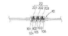
流量制御部10は、図3に示すように、直列に配置されたアンブレラタイプの開放圧の異なる複数の逆止弁102、103、104を備え、かつこの逆止弁102、103、104が、軸上に薬液流路104、105、106を有してなるものであってもよい。この場合、逆止弁選択手段20としては逆止弁102、103、104の薬液流路104、105、106を閉塞する手段201、202、203が採用され、逆止弁102、103、104の薬液流路104、105、106の1つが逆止弁選択手段20により閉塞されたときに、その薬液流路104または105、106の閉塞された逆止弁102または103、104が逆止弁として機能するようになっている。このような薬液流路閉塞手段201、202、203として機能する逆止弁選択手段20は、流量選択部10の側壁に設けられるのが好ましい。
【0011】
次に、図3に示す注入速度調整装置による注入速度の調整について、図4を用いて説明する。
(A)は薬液流路閉塞手段201により逆止弁101の薬液流路104が閉塞された場合であり、注入速度は逆止弁101の開放圧によって調整される。
(B)は薬液流路閉塞手段202により逆止弁102の薬液流路105が閉塞された場合であり、注入速度は逆止弁102の開放圧によって調整される。
(C)は薬液流路閉塞手段203により逆止弁103の薬液流路106が閉塞された場合であり、注入速度は逆止弁103の開放圧によって調整される。
【0012】
〔実施例1〜2〕
図1に示すタイプの注入速度調整装置において、逆止弁13、14、15の開放圧の組み合わせを、夫々、2.5kPa、5kPa、10kPaにした場合(実施例1)と、12.5kPa、25kPa、30kPaにした場合(実施例2)で、リザーバーの加圧力を60kPaに設定して流量の減少率を測定したところ、表1に示すような結果が得られた。弁の開放圧2.5kPaにつき約4.2%の流量の減少が認められる。
【0013】
【表1】

【発明の効果】
以上説明してきたことから明らかなように、本発明の注入速度調整装置を採用することにより、薬液注入器の注入速度の設定操作が容易になる。また、薬液注入器の注入速度調整装置を安価に提供することができる。
【図面の簡単な説明】
【図1】 本発明の一実施例を示す縦断面図である。
【図2】 図1に示す注入速度調整装置の作用を説明するための図である。
【図3】 本発明の他の実施例を示す図である。
【図4】 図3に示す注入速度調整装置の作用を説明するための図である。
【図5】 図1に示す注入速度注入装置を用いた薬液注入器の一例を示す図である。
【符号の説明】
1 流量制御部
11 管状体
11 先端部
111 先端部の管腔
12 基端部
121 基端部の管腔
122 雄型螺合手段
13、14、15 逆止弁
16 Oリング
2 逆止弁選択手段
21 管状体
211 相対的に径の小さい部分
212 相対的に径の大きい部分
213 環状突起
214 環状リブ
215 内腔
10 流量制御部
101、102、103 逆止弁
104、105、106 薬液流路
20 逆止弁選択手段
201、202、203 薬液流路閉塞手段
3 コネクター
4 流量制御装置
5 フィルター
6 クランプ
7 リザーバー
31、41、51、71 接続チューブ
C 注入速度調整装置[0001]
BACKGROUND OF THE INVENTION
In the present invention, for example, an anesthetic, an analgesic, an anticancer drug, an antibiotic or the like stored in a drug reservoir is pushed into a patient's body by a contraction force of a rubber elastic body, a spring extension force, or a negative pressure chamber. The present invention relates to an injection rate adjusting device for a chemical injector that injects a minute amount using pressure or the like.
[0002]
[Prior art]
Conventionally, chemical injectors that pressurize the chemical reservoir using the elastic force of the elastic rubber body and inject a small amount of the chemical in the chemical reservoir into the patient's body have traditionally used capillaries to adjust the injection speed. The flow rate of the chemical solution was attenuated by the pipe line resistance. Therefore, the injection rate can be adjusted to an arbitrary value by adjusting the inner diameter and length of the narrow tube. Therefore, there is usually a product in which one capillary is provided for one reservoir and the injection rate is set. It was.
However, in recent years, in response to changes in the patient's condition, it may be necessary to change the injection speed in the middle of the drug solution injection. A plurality of thin tubes with different control speeds are connected to the stopcocks, and the speed is made variable by switching the stopcocks (Japanese Patent Laid-Open Nos. 9-280394 and 10-28741), or a plurality of thin tubes in parallel An arrangement in which the speed is made variable by opening and closing each thin tube with a clamp (JP-A-10-113386, etc.) has been proposed.
[0003]
However, in the above method, the flow path of the chemical solution is very complicated, and the operation for setting the inflow speed of the narrow tube is relatively difficult. In addition, a chemical solution injector that attenuates the pressure applied to the reservoir by the tube resistance of the narrow tube can adjust the flow rate relatively accurately within ± 10%. Since the accuracy is affected by the tolerance of the inner diameter of the tube, it is very precise. Therefore, it is very expensive to use a plurality of these.
[0004]
[Problems to be solved by the invention]
The present invention has been made in view of the above circumstances, and an object of the present invention is to provide an injection rate adjusting device for a chemical solution injector that is easy to set an injection rate and greatly improved in cost.
[0005]
[Means for Solving the Problems]
As a result of intensive studies to solve the above problems, the present inventor has arranged a plurality of check valves having different opening pressures in series or in parallel in the flow path, and tried to adjust from these check valves. The present invention has been completed by conceiving that it is sufficient to select a check valve in accordance with the flow rate. That is, the present invention includes a tubular flow rate control unit including a plurality of check valves of a duckbill type arranged in series from the upstream side to the downstream side in order of increasing opening pressure and having a plurality of check valves having different opening pressures. A check valve that adjusts the injection speed from the check valve of the flow rate control unit, and is inserted into the lumen of the flow rate control unit from the upstream side so as to be able to penetrate the check valve And a check valve selecting means for adjusting the injection speed by the most upstream check valve that is not penetrated by the rod . Here, the check valve selection means including the rod is provided with a female screwing means rotatably provided on the outer periphery of the rod, and this female screwing means is provided at the base end of the flow rate control unit. It is preferable that the rod is moved within the lumen of the flow rate control unit by engaging with and rotating the male screw means. In addition, the present invention provides a tubular flow rate control unit having a plurality of check valves of different umbrella-type opening pressures arranged in series, and a reverse flow rate adjusting unit that adjusts the injection rate from the check valves of the flow rate control unit. And a check valve selecting means for selecting a stop valve, and the check valve has a chemical liquid channel on the shaft, and one of the chemical liquid channels is blocked by the check valve selecting means. In some cases, the check rate valve of the chemical solution flow path may be a check valve in which the chemical solution channel is shut off to function as a check valve . In this case, as the check valve selection means, means for closing the chemical liquid flow path of the check valve is adopted, and when one of the chemical liquid flow paths of the check valve is closed by the check valve selection means, the chemical liquid A check valve whose channel is blocked functions as a check valve. It is preferable that the check valve selection means functioning as such a chemical liquid flow path closing means is provided on the side wall of the flow rate selection unit.
[0006]
DETAILED DESCRIPTION OF THE INVENTION
Next, embodiments of the present invention will be described with reference to the drawings.
FIG. 1 is a longitudinal sectional view showing an embodiment of the present invention, and FIG. 2 is a view for explaining the operation of the injection rate adjusting device shown in FIG. FIG. 3 is a view showing another embodiment of the present invention, and FIG. 4 is a view for explaining the operation of the injection rate adjusting device shown in FIG. FIG. 5 is a view showing an example of a chemical solution injector using the injection rate injection apparatus shown in FIG.
As shown in FIGS. 1 and 3, the injection rate adjusting device of the present invention includes tubular
[0007]
The injection rate adjusting device shown in FIG. 1 includes a tubular flow rate control unit 1 including a plurality of duckbill-
The flow rate control unit 1 is a tubular body composed of a distal end portion 11 and a
[0008]
The check valve selection means 2 has a distal end and a proximal end, and is inserted from the upstream side of the flow rate control unit 1 and can pass through the
The injection speed adjusting device C is arranged downstream of the flow rate control device 4 in the chemical solution injector as shown in FIG. 5, and adjusts the flow rate of the chemical solution discharged from the reservoir 7 and controlled to a desired flow rate by the flow rate control device 4. . In the figure, 3 is a connector, 31, 41, 51 and 71 are connection tubes, 5 is a filter, and 6 is a clamp.
[0009]
Next, the adjustment of the injection rate by the injection rate adjusting device shown in FIG. 1 will be described with reference to FIG.
(A) is a case where none of the
(B) is a case where only the
(C) is a case where the
(D) is a case where the
[0010]
Next, another embodiment of the present invention will be described.
As shown in FIG. 3, the flow
[0011]
Next, the adjustment of the injection rate by the injection rate adjusting device shown in FIG. 3 will be described with reference to FIG.
(A) is a case where the chemical
(B) is a case where the
(C) is a case where the
[0012]
[Examples 1-2]
In the injection rate adjusting device of the type shown in FIG. 1, when the combination of the release pressures of the
[0013]
[Table 1]
【The invention's effect】
As is apparent from the above description, the setting operation of the injection rate of the chemical solution injector is facilitated by employing the injection rate adjusting device of the present invention. Moreover, the injection rate adjusting device for the chemical solution injector can be provided at low cost.
[Brief description of the drawings]
FIG. 1 is a longitudinal sectional view showing an embodiment of the present invention.
FIG. 2 is a view for explaining the operation of the injection rate adjusting device shown in FIG. 1;
FIG. 3 is a diagram showing another embodiment of the present invention.
4 is a view for explaining the operation of the injection rate adjusting device shown in FIG.
FIG. 5 is a view showing an example of a chemical solution injector using the injection rate injection device shown in FIG. 1;
[Explanation of symbols]
DESCRIPTION OF SYMBOLS 1 Flow control part 11 Tubular body 11
Claims (4)
Priority Applications (4)
| Application Number | Priority Date | Filing Date | Title |
|---|---|---|---|
| JP2000053236A JP4010005B2 (en) | 2000-02-29 | 2000-02-29 | Device for adjusting injection speed of chemical injector |
| EP01104416A EP1129740B1 (en) | 2000-02-29 | 2001-02-26 | Infusion rate adjusting device for drug solution injector |
| DE60103674T DE60103674T2 (en) | 2000-02-29 | 2001-02-26 | Device for controlling the infusion rate of a medication delivery device |
| US09/794,136 US6554805B2 (en) | 2000-02-29 | 2001-02-28 | Infusion rate adjusting device for drug solution injector |
Applications Claiming Priority (1)
| Application Number | Priority Date | Filing Date | Title |
|---|---|---|---|
| JP2000053236A JP4010005B2 (en) | 2000-02-29 | 2000-02-29 | Device for adjusting injection speed of chemical injector |
Related Child Applications (1)
| Application Number | Title | Priority Date | Filing Date |
|---|---|---|---|
| JP2007189348A Division JP2007330800A (en) | 2007-07-20 | 2007-07-20 | Infusion speed adjusting device of chemical syringe |
Publications (3)
| Publication Number | Publication Date |
|---|---|
| JP2001238950A JP2001238950A (en) | 2001-09-04 |
| JP2001238950A5 JP2001238950A5 (en) | 2005-05-26 |
| JP4010005B2 true JP4010005B2 (en) | 2007-11-21 |
Family
ID=18574651
Family Applications (1)
| Application Number | Title | Priority Date | Filing Date |
|---|---|---|---|
| JP2000053236A Expired - Fee Related JP4010005B2 (en) | 2000-02-29 | 2000-02-29 | Device for adjusting injection speed of chemical injector |
Country Status (4)
| Country | Link |
|---|---|
| US (1) | US6554805B2 (en) |
| EP (1) | EP1129740B1 (en) |
| JP (1) | JP4010005B2 (en) |
| DE (1) | DE60103674T2 (en) |
Families Citing this family (51)
| Publication number | Priority date | Publication date | Assignee | Title |
|---|---|---|---|---|
| US6679865B2 (en) * | 2001-12-07 | 2004-01-20 | Nedrip Ltd. | Fluid flow meter for gravity fed intravenous fluid delivery systems |
| US8626257B2 (en) | 2003-08-01 | 2014-01-07 | Dexcom, Inc. | Analyte sensor |
| US9135402B2 (en) | 2007-12-17 | 2015-09-15 | Dexcom, Inc. | Systems and methods for processing sensor data |
| US20190357827A1 (en) | 2003-08-01 | 2019-11-28 | Dexcom, Inc. | Analyte sensor |
| US7591801B2 (en) | 2004-02-26 | 2009-09-22 | Dexcom, Inc. | Integrated delivery device for continuous glucose sensor |
| US8886273B2 (en) | 2003-08-01 | 2014-11-11 | Dexcom, Inc. | Analyte sensor |
| US7920906B2 (en) | 2005-03-10 | 2011-04-05 | Dexcom, Inc. | System and methods for processing analyte sensor data for sensor calibration |
| US9247900B2 (en) | 2004-07-13 | 2016-02-02 | Dexcom, Inc. | Analyte sensor |
| US8423114B2 (en) | 2006-10-04 | 2013-04-16 | Dexcom, Inc. | Dual electrode system for a continuous analyte sensor |
| US11633133B2 (en) | 2003-12-05 | 2023-04-25 | Dexcom, Inc. | Dual electrode system for a continuous analyte sensor |
| US8364230B2 (en) | 2006-10-04 | 2013-01-29 | Dexcom, Inc. | Analyte sensor |
| US8287453B2 (en) | 2003-12-05 | 2012-10-16 | Dexcom, Inc. | Analyte sensor |
| US8774886B2 (en) | 2006-10-04 | 2014-07-08 | Dexcom, Inc. | Analyte sensor |
| US8425417B2 (en) | 2003-12-05 | 2013-04-23 | Dexcom, Inc. | Integrated device for continuous in vivo analyte detection and simultaneous control of an infusion device |
| US8425416B2 (en) | 2006-10-04 | 2013-04-23 | Dexcom, Inc. | Analyte sensor |
| US8364231B2 (en) | 2006-10-04 | 2013-01-29 | Dexcom, Inc. | Analyte sensor |
| WO2009048462A1 (en) | 2007-10-09 | 2009-04-16 | Dexcom, Inc. | Integrated insulin delivery system with continuous glucose sensor |
| US8808228B2 (en) | 2004-02-26 | 2014-08-19 | Dexcom, Inc. | Integrated medicament delivery device for use with continuous analyte sensor |
| US8177760B2 (en) | 2004-05-12 | 2012-05-15 | C. R. Bard, Inc. | Valved connector |
| US7347853B2 (en) * | 2004-05-12 | 2008-03-25 | C. R. Bard, Inc. | Catheter with removable extension |
| US7783333B2 (en) | 2004-07-13 | 2010-08-24 | Dexcom, Inc. | Transcutaneous medical device with variable stiffness |
| US7713574B2 (en) | 2004-07-13 | 2010-05-11 | Dexcom, Inc. | Transcutaneous analyte sensor |
| US20070045902A1 (en) | 2004-07-13 | 2007-03-01 | Brauker James H | Analyte sensor |
| US7857760B2 (en) | 2004-07-13 | 2010-12-28 | Dexcom, Inc. | Analyte sensor |
| US7766886B2 (en) * | 2005-07-30 | 2010-08-03 | The Regents Of The University Of California | Drainage devices and methods |
| US20070078442A1 (en) * | 2005-08-24 | 2007-04-05 | Mayse Martin L | Tapered attachment for pleural catheter |
| KR20080078028A (en) * | 2005-12-12 | 2008-08-26 | 아큐 레이트 피이티와이 리미티이드 | Flow control assembly including a valve and flow controller |
| CN101374567B (en) | 2006-01-17 | 2011-01-26 | 株式会社Jms | Water passage control device and medical infusion circuit using the same |
| US8447376B2 (en) | 2006-10-04 | 2013-05-21 | Dexcom, Inc. | Analyte sensor |
| US8562528B2 (en) | 2006-10-04 | 2013-10-22 | Dexcom, Inc. | Analyte sensor |
| US8478377B2 (en) | 2006-10-04 | 2013-07-02 | Dexcom, Inc. | Analyte sensor |
| US8298142B2 (en) | 2006-10-04 | 2012-10-30 | Dexcom, Inc. | Analyte sensor |
| US8449464B2 (en) | 2006-10-04 | 2013-05-28 | Dexcom, Inc. | Analyte sensor |
| US8275438B2 (en) | 2006-10-04 | 2012-09-25 | Dexcom, Inc. | Analyte sensor |
| US20080306434A1 (en) | 2007-06-08 | 2008-12-11 | Dexcom, Inc. | Integrated medicament delivery device for use with continuous analyte sensor |
| US8417312B2 (en) | 2007-10-25 | 2013-04-09 | Dexcom, Inc. | Systems and methods for processing sensor data |
| US9839395B2 (en) | 2007-12-17 | 2017-12-12 | Dexcom, Inc. | Systems and methods for processing sensor data |
| US8396528B2 (en) | 2008-03-25 | 2013-03-12 | Dexcom, Inc. | Analyte sensor |
| JPWO2010010870A1 (en) * | 2008-07-25 | 2012-01-05 | 株式会社根本杏林堂 | Medical connector device |
| US8574203B2 (en) | 2009-02-11 | 2013-11-05 | Becton, Dickinson And Company | Systems and methods for providing a flushable catheter assembly |
| EP4324399A3 (en) | 2011-04-15 | 2024-05-15 | DexCom, Inc. | Advanced analyte sensor calibration and error detection |
| US9155863B2 (en) | 2011-10-06 | 2015-10-13 | Becton, Dickinson And Company | Multiple use stretching and non-penetrating blood control valves |
| US9358364B2 (en) * | 2011-10-06 | 2016-06-07 | Becton, Dickinson And Company | Activator attachment for blood control catheters |
| US9155876B2 (en) | 2011-10-06 | 2015-10-13 | Becton, Dickinson And Company | Port valve of a blood control catheter |
| US9126012B2 (en) | 2011-10-06 | 2015-09-08 | Becton, Dickinson And Company | Intravenous catheter with duckbill valve |
| US9750925B2 (en) | 2014-01-21 | 2017-09-05 | Becton, Dickinson And Company | Ported catheter adapter having combined port and blood control valve with venting |
| ES2964749T3 (en) * | 2015-12-10 | 2024-04-09 | Nipro Corp | Medical liquid delivery device |
| CA2995280A1 (en) * | 2017-02-16 | 2018-08-16 | Medquest Medical Inc. | Connector for catheter |
| US11331022B2 (en) | 2017-10-24 | 2022-05-17 | Dexcom, Inc. | Pre-connected analyte sensors |
| CN212438615U (en) | 2017-10-24 | 2021-02-02 | 德克斯康公司 | Wearable device |
| US20200222681A1 (en) * | 2019-01-14 | 2020-07-16 | Becton, Dickinson And Company | Needleless access connector facilitating instrument delivery to a catheter assembly |
Family Cites Families (12)
| Publication number | Priority date | Publication date | Assignee | Title |
|---|---|---|---|---|
| US3941149A (en) * | 1974-11-11 | 1976-03-02 | Baxter Laboratories, Inc. | Valve |
| US4246932A (en) * | 1979-10-18 | 1981-01-27 | Burron Medical, Inc. | Multiple additive valve assembly |
| US4729401A (en) * | 1987-01-29 | 1988-03-08 | Burron Medical Inc. | Aspiration assembly having dual co-axial check valves |
| US4756982A (en) * | 1987-11-09 | 1988-07-12 | General Motors Corporation | Dual seal battery vent valve |
| US4919167A (en) * | 1989-03-17 | 1990-04-24 | Manska Wayne E | Check valve |
| US5310094A (en) * | 1991-11-15 | 1994-05-10 | Jsp Partners, L.P. | Preservative free sterile fluid dispensing system |
| US5618268A (en) * | 1995-06-06 | 1997-04-08 | B. Braun Medical Inc. | Medical infusion devices and medicine delivery systems employing the same |
| DE29519322U1 (en) * | 1995-12-06 | 1996-02-15 | Jokisch, Thomas Michael, 45661 Recklinghausen | Check valve for fluids with small pressure differences, especially for medical technology and aquaristics |
| JP3203636B2 (en) | 1996-04-10 | 2001-08-27 | ニプロ株式会社 | Flow control device |
| JP3266901B2 (en) | 1996-07-17 | 2002-03-18 | ニプロ株式会社 | Multi-stage flow switching device |
| JP3269073B2 (en) | 1996-10-15 | 2002-03-25 | ニプロ株式会社 | Multi-stage flow switching device |
| FR2776742B1 (en) * | 1998-03-30 | 2000-06-02 | Medex Sa | IMPROVEMENT FOR THRESHOLD VALVE |
-
2000
- 2000-02-29 JP JP2000053236A patent/JP4010005B2/en not_active Expired - Fee Related
-
2001
- 2001-02-26 DE DE60103674T patent/DE60103674T2/en not_active Expired - Lifetime
- 2001-02-26 EP EP01104416A patent/EP1129740B1/en not_active Expired - Lifetime
- 2001-02-28 US US09/794,136 patent/US6554805B2/en not_active Expired - Fee Related
Also Published As
| Publication number | Publication date |
|---|---|
| DE60103674D1 (en) | 2004-07-15 |
| DE60103674T2 (en) | 2004-10-21 |
| EP1129740A2 (en) | 2001-09-05 |
| EP1129740A3 (en) | 2002-06-12 |
| US20010021829A1 (en) | 2001-09-13 |
| JP2001238950A (en) | 2001-09-04 |
| EP1129740B1 (en) | 2004-06-09 |
| US6554805B2 (en) | 2003-04-29 |
Similar Documents
| Publication | Publication Date | Title |
|---|---|---|
| JP4010005B2 (en) | Device for adjusting injection speed of chemical injector | |
| KR101659640B1 (en) | Medical valve with improved back-pressure sealing | |
| CN208464909U (en) | Intravenous access device and peripheral venous catheter with flowing steering characteristic portion | |
| JP6198739B2 (en) | Catheter improvements | |
| EP1946792B1 (en) | Male luer connector | |
| JP2001238950A5 (en) | ||
| AU2014273828A1 (en) | A catheter system | |
| JP2007330800A (en) | Infusion speed adjusting device of chemical syringe | |
| JPH1028741A (en) | Multi-stage type flow rate switching device | |
| JPH0687895B2 (en) | Balloon Infuser | |
| JP6646735B2 (en) | Variable fluid flow control device | |
| CN218923512U (en) | Catheter for ureteroscope operation | |
| CN212118694U (en) | Continuous bladder irrigator | |
| EP3592417B1 (en) | Catheter valve | |
| JP2002500534A (en) | Catheter insertion device having device for fluid-tight clamping of insertion lumen | |
| CN111212669A (en) | Cannula for fluid infusion | |
| CN209154651U (en) | Vacuum suction occlusion catheter and negative pressure suction device | |
| CA1134234A (en) | Flow regulating device for arterial catheter systems | |
| CN117982754A (en) | Medical injector | |
| JPH0496761A (en) | Balloon body for injecting chemical and instrument for injecting chemical using it | |
| JP2012055592A (en) | Drug solution administration appliance | |
| IE20040569A1 (en) | A haemostasis device |
Legal Events
| Date | Code | Title | Description |
|---|---|---|---|
| A521 | Written amendment |
Free format text: JAPANESE INTERMEDIATE CODE: A523 Effective date: 20040727 |
|
| A621 | Written request for application examination |
Free format text: JAPANESE INTERMEDIATE CODE: A621 Effective date: 20040727 |
|
| A977 | Report on retrieval |
Free format text: JAPANESE INTERMEDIATE CODE: A971007 Effective date: 20061201 |
|
| A131 | Notification of reasons for refusal |
Free format text: JAPANESE INTERMEDIATE CODE: A131 Effective date: 20070109 |
|
| A521 | Written amendment |
Free format text: JAPANESE INTERMEDIATE CODE: A523 Effective date: 20070308 |
|
| A02 | Decision of refusal |
Free format text: JAPANESE INTERMEDIATE CODE: A02 Effective date: 20070523 |
|
| A521 | Written amendment |
Free format text: JAPANESE INTERMEDIATE CODE: A523 Effective date: 20070720 |
|
| A911 | Transfer of reconsideration by examiner before appeal (zenchi) |
Free format text: JAPANESE INTERMEDIATE CODE: A911 Effective date: 20070730 |
|
| TRDD | Decision of grant or rejection written | ||
| A01 | Written decision to grant a patent or to grant a registration (utility model) |
Free format text: JAPANESE INTERMEDIATE CODE: A01 Effective date: 20070813 |
|
| A61 | First payment of annual fees (during grant procedure) |
Free format text: JAPANESE INTERMEDIATE CODE: A61 Effective date: 20070826 |
|
| R150 | Certificate of patent or registration of utility model |
Free format text: JAPANESE INTERMEDIATE CODE: R150 Ref document number: 4010005 Country of ref document: JP Free format text: JAPANESE INTERMEDIATE CODE: R150 |
|
| FPAY | Renewal fee payment (event date is renewal date of database) |
Free format text: PAYMENT UNTIL: 20100914 Year of fee payment: 3 |
|
| FPAY | Renewal fee payment (event date is renewal date of database) |
Free format text: PAYMENT UNTIL: 20130914 Year of fee payment: 6 |
|
| R250 | Receipt of annual fees |
Free format text: JAPANESE INTERMEDIATE CODE: R250 |
|
| R250 | Receipt of annual fees |
Free format text: JAPANESE INTERMEDIATE CODE: R250 |
|
| R250 | Receipt of annual fees |
Free format text: JAPANESE INTERMEDIATE CODE: R250 |
|
| LAPS | Cancellation because of no payment of annual fees |