JP4009671B2 - Discontinuous countercurrent chromatography method and apparatus - Google Patents
Discontinuous countercurrent chromatography method and apparatus Download PDFInfo
- Publication number
- JP4009671B2 JP4009671B2 JP52010597A JP52010597A JP4009671B2 JP 4009671 B2 JP4009671 B2 JP 4009671B2 JP 52010597 A JP52010597 A JP 52010597A JP 52010597 A JP52010597 A JP 52010597A JP 4009671 B2 JP4009671 B2 JP 4009671B2
- Authority
- JP
- Japan
- Prior art keywords
- pump
- sample
- chromatography
- solvent
- cycle
- Prior art date
- Legal status (The legal status is an assumption and is not a legal conclusion. Google has not performed a legal analysis and makes no representation as to the accuracy of the status listed.)
- Expired - Fee Related
Links
Images


Classifications
-
- B—PERFORMING OPERATIONS; TRANSPORTING
- B01—PHYSICAL OR CHEMICAL PROCESSES OR APPARATUS IN GENERAL
- B01D—SEPARATION
- B01D15/00—Separating processes involving the treatment of liquids with solid sorbents; Apparatus therefor
- B01D15/08—Selective adsorption, e.g. chromatography
- B01D15/10—Selective adsorption, e.g. chromatography characterised by constructional or operational features
- B01D15/18—Selective adsorption, e.g. chromatography characterised by constructional or operational features relating to flow patterns
- B01D15/1814—Selective adsorption, e.g. chromatography characterised by constructional or operational features relating to flow patterns recycling of the fraction to be distributed
-
- B—PERFORMING OPERATIONS; TRANSPORTING
- B01—PHYSICAL OR CHEMICAL PROCESSES OR APPARATUS IN GENERAL
- B01D—SEPARATION
- B01D15/00—Separating processes involving the treatment of liquids with solid sorbents; Apparatus therefor
- B01D15/08—Selective adsorption, e.g. chromatography
- B01D15/10—Selective adsorption, e.g. chromatography characterised by constructional or operational features
- B01D15/18—Selective adsorption, e.g. chromatography characterised by constructional or operational features relating to flow patterns
- B01D15/1864—Selective adsorption, e.g. chromatography characterised by constructional or operational features relating to flow patterns using two or more columns
-
- G—PHYSICS
- G01—MEASURING; TESTING
- G01N—INVESTIGATING OR ANALYSING MATERIALS BY DETERMINING THEIR CHEMICAL OR PHYSICAL PROPERTIES
- G01N30/00—Investigating or analysing materials by separation into components using adsorption, absorption or similar phenomena or using ion-exchange, e.g. chromatography or field flow fractionation
- G01N30/02—Column chromatography
- G01N30/26—Conditioning of the fluid carrier; Flow patterns
- G01N30/38—Flow patterns
- G01N30/44—Flow patterns using recycling of the fraction to be distributed
-
- B—PERFORMING OPERATIONS; TRANSPORTING
- B01—PHYSICAL OR CHEMICAL PROCESSES OR APPARATUS IN GENERAL
- B01D—SEPARATION
- B01D15/00—Separating processes involving the treatment of liquids with solid sorbents; Apparatus therefor
- B01D15/08—Selective adsorption, e.g. chromatography
- B01D15/10—Selective adsorption, e.g. chromatography characterised by constructional or operational features
- B01D15/18—Selective adsorption, e.g. chromatography characterised by constructional or operational features relating to flow patterns
- B01D15/1814—Selective adsorption, e.g. chromatography characterised by constructional or operational features relating to flow patterns recycling of the fraction to be distributed
- B01D15/1857—Reactive simulated moving beds
Landscapes
- Chemical & Material Sciences (AREA)
- Analytical Chemistry (AREA)
- Life Sciences & Earth Sciences (AREA)
- Sustainable Development (AREA)
- Chemical Kinetics & Catalysis (AREA)
- Biochemistry (AREA)
- Health & Medical Sciences (AREA)
- General Health & Medical Sciences (AREA)
- General Physics & Mathematics (AREA)
- Immunology (AREA)
- Pathology (AREA)
- Physics & Mathematics (AREA)
- Treatment Of Liquids With Adsorbents In General (AREA)
Description
技術分野
本発明は、効率的かつ反復的方法で分取クロマトグラフィーを行う方法およびその装置に関する。
背景技術
数多くの提案されそして利用されているクロマトグラフィーの手法の中に、(1)外部リサイクルを伴う高速液体クロマトグラフィー(HPLC)および(2)擬似床式(SMB)クロマトグラフィーがある。外部HPLCリサイクリングは少なくとも1974年から知られている(R.A.Henry,S.H.Byrne及びD.R.Hudson,J.Chromatographic Sci.12,197(1974))。外部リサイクリングにおいて、理論段数を増加するためにクロマトグラフィーピークを8の字パターンの二つのカラムを通して循環させる。リサイクリングの過程で、ピークはポンプを通らない。従って、この手法はピークが各サイクルでポンプを通り、混合およびカラムで起こる分離の幾分かの相殺をさせる閉鎖ループリサイクリングよりも効率的である。1960年代の初めにUOPの人達(D.B.Broughton,R.W.Neuzil,J.M.Pharis,C.S.Brearley,Chem.Eng.Progress,66(9),70,(1970))によって発明されたSMBクロマトグラフィーは、連続的な方法である。供給は絶えずSMBクロマトグラフィーサンプルの中に注入され、抽出と非抽出とが絶えず集められ、また新しい移動相が絶えず加えられる。全クロマトグラフィーサンプルがシステムを移動する。例えば、16カラム配列の一つの可能な配置において、供給をカラム7および8の間で注入し、移動相をカラム16および1の間で注入し、非抽出をカラム11および12の間で集め、抽出をカラム3および4の間で集める。プロフィールが右に動くにつれ、全ての注入と捕集ポイントが同時に一カラム右にスイッチする。
例えば、供給ポイントは8と9の間、移動相ポイントは1と2の間、非抽出ポイントは12と13の間、抽出ポイントは4と5の間である。スイッチングは定期的に適当な時間で起こる。供給と移動相のポイントで注入された液体を非抽出と抽出のポイントで集め、定常状態となる。SMBクロマトグラフィーの別の特徴は、クロマトグラフィーサンプルを通して四つの流速があることである。また、古典的なSMBクロマトグラフィーは真に連続的であり、移動相と供給ポンプは物質をシステムに送ることを決して止めず、抽出と非抽出のラインは集められた精製物質を配送することを決して止めないということが強調されるべきである。
また、先行技術には関連する三つの特許、即ちUSP4,267,054、USP4,379,751およびUSP4,970,002がある。しかし、これらの特許の方法は閉鎖ループリサイクリングを用いている。
発明の要約
本発明の課題は、経済的かつ効果的なHPLC方法を提供することである。別の課題は、そのような方法に対する装置を提供することである。
明細書および添付された請求項を更に研究すれば、本発明の更なる目的と利点が当業者に明らかになろう。
それらの目的を達成するために、本発明の一つの面は新しいサンプルの定期的な注入と結びついたリサイクリング手法を採用することである。
本発明の別の面は、或るフラクションを集めている間に循環クロマトグラフィーサンプルを止めることを防ぐ第二の溶媒ポンプ(添付した図のポンプ2として参照される)の使用にある。この特徴は、方法の生産性を大いに向上することである。従って、二つのカラムに対して二つのポンプの使用は、それ自体新規で且つ有用な補助結合である。
本発明の好ましい修飾として、検出器は本発明の実施に必須ではないが、検出器が用いられる。検出器の好ましい使用によって、全体の方法が視角的且つ直感的になり、手法の開発を促進する。更に重要なことは、検出器が全ての捕集および制御操作、例えばフラクションの捕集、新しいサンプルの注入、カラムのスイッチ、ポンプ制御等の開始にソフトウエアーの使用を可能にする。上昇または下降スロープ、特徴的吸光度、二つの吸光度の比、吸光度の機能、屈折インデックス、伝導度、pH、特徴的光学活性等のパラメータを測定することによって、そのようなソフトウエアーは、与えられた操作を始めるために循環クロマトグラフィーサンプル上に正しいポイントを決める。またソフトウエアーは捕集および制御操作を予定された操作にする。例えば、タイマーと連動する上昇スロープの検知が非常に満足なプロセスとなる。
本発明の別の態様では、注入中に移動相ポンプのスイッチを切ることができる。このことは新しいサンプルを部分的に分離された循環クロマトグラフィーサンプルと混合することを避け、結果として明確に改善された分離となる。この手法は困難な分離において、特に有用である。勿論、適宜移動相ポンプのスイッチを注入中着けたままにできる。
本発明の別の態様として、より後で溶離するフラクションを溶離するために強溶媒のパルスを発生したり、これらのフラクションを濃縮したりするメカニズムが提供される。
本発明の方法を遂行するために、装置の構成は、二つの分取クロマトグラフィーカラム、カラムのスイッチングに用いられる二つの四方バルブ、少なくとも一つおよび好ましくは二つの溶媒ポンプ(ポンプ1および2)、注入ポンプ(またはシステム)および好ましくは、移動相を廃液に送るためまたはそれをポンプ1にリサイクルするために使用される三方リサイクルバルブを含んでいる。どのようなタイプの分取クロマトグラフィーカラムも使用できる。各々のカラムは、好ましくは同じタイプおよび量の固定相またはそれと同等のもので詰められる。最良の結果を得るには、カラムは理論段数(number of theoretical plates)で計られたのとほぼ同じ効率を有するべきである。
好ましくはまた検出器、コンピューター及びオートメーションソフトウエアーを備えている。また好ましくは、バルブスイッチング、ポンプのつまみをつけたりはずしたり、ポンプ流速を調節することを含むが、これらに限定されない制御操作の、全てではないにしても、いくつかは専ら時間に基づくソフトウエアーによって開始される。反対に、検出器が用いられない場合、分離の進展と成功を、フラクションの定期的および/またはオンラインサンプリング、ついで分取クロマトグラフィー方法と関係のない分析器によるフラクションの分析によって決定することが好ましい。
本方法は、順相(normal phase)クロマトグラフィー分離、逆相クロマトグラフィー分離、キラルクロマトグラフィー分離、イオン交換クロマトグラフィー分離、アフィニティクロマトグラフィー分離およびサイズ排除(size exclusion)クロマトグラフィー分離を含むが、これに限定されないどのようなタイプのクロマトグラフィー分離を行うためにも使用される。
図の簡単な説明
本発明をよりよく理解するために、液性混合物のフラクションへのクロマトグラフィー分離の手法およびクロマトグラフィー態様を説明する実施例の詳しい記載を以下の図に関連しておこなう。ここで、
図1は本発明の一般的な図式フローチャートである;
図2は図1とは六方配列バルブを使用することが異なる本発明の別のフローチャートである;
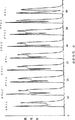
図3は実施例1のクロマトグラムである;
図4は実施例1のサイクル6のグラフである;
図5は実施例2のクロマトグラムである;
図6は実施例3のクロマトグラムである;
図7は実施例3のサイクル3のグラフである;
図8は実施例4のクロマトグラムである;
図9は実施例5において使用されるシステムの図式フローチャートであり、図2における六方配列バルブの代りに第三の四方バルブを有しており、またより精巧なフラクション捕集システムを付けている;
図10は実施例5のクロマトグラムである;
図11は実施例5のサイクル4のグラフである;
図12は図1に類似する本発明の図式フローチャートであるが、三方バルブと一般化されたフラクション捕集システムを表わしている;
図13は図1に類似しているが、フラクション捕集システムが二方捕集バルブシステムである;
図14は図1に類似する図式フローチャートであり、フラクション捕集システムが一連の高圧三方バルブである;
図15は図1を修飾した図式フローチャートであり、ポンプ2がサンプルの注入に用いられ、それによって注入ポンプを除く;
図16は図1に類似する図式フローチャートであるが、検定された注入ループを使用する;
図17は図2に類似するが、図9のフラクション捕集システムを使用する。
図の詳細な説明
最初に、図1および他の図の略“PT”は“加圧変換器”を表わす。略“P1...P5”は空気が導入されるようにするバルブセッティングを表わし、略“V1...V5”はフラクションを集めるバルブセッティングを表わす。
図1は本発明の一般化された図式ダイアグラムを示す。分取クロマトグラフィーにおいて使用される実際上どのようなタイプのフラクション捕集システムも精製物を集めるために使用される。示された簡単な注入ポンプ以外の自動サンプル注入手法も可能である。二つの四方バルブが循環クロマトグラフィーサンプルを適当なカラムへ切り替える役割をする。それらは同時に切り替わる。この事項は定時的な操作である。
ポンプ1および2は移動相ポンプである。ポンプ1の流速は作業の初めにプログラムに入れられる。ポンプ1は注入の間スイッチをはずされる。このことは新しいサンプルと部分的に分離された循環クロマトグラフィーサンプルとの混合を妨げるので有用である。ポンプ1のこのスイッチをはずすことは定時的な操作であってもよく、またはそれはシステムおよびソフトウエアーによって決定された対応パラメータによって起こされる。
ポンプ1は溶媒Aまたは溶媒Bのいずれかを送ることができることに注目せよ。溶媒Aは分離溶媒であり、最良の分離を与えるように決定された移動相である。溶媒Bはより強溶媒であり、例えば容量80:20のメタノール−水溶液と比べた100%メタノールである。溶媒Bの短いパルスは、より滞留した成分をフラクション捕集システムによって集めたり、廃棄するように、対応するカラムの洗浄に使用することができる。(「パルス」とは、例えば、全サイクルの時間の約1−10%持続する溶媒Bの瞬間的な注入を意味する。)より強溶媒のこのパルスはこれらのフラクションを集めるために必要とする時間を減少させ、またこれらのフラクションの濃度を顕著に高める。所望の量の溶媒Bが対応するカラムに送られた後、溶媒Aが再度ポンプ1に対して選ばれる。循環クロマトグラフィーサンプルがこのカラムにスイッチされる迄に、カラムを溶媒Aで平衡状態にする。溶媒Aと溶媒Bの切り替えは定時的な操作であってもよく、またはそれはシステムおよびソフトウエアーによって決定された対応パラメータによって起こされる。
サンプルの新しい部分の注入後におこるフラクション捕集中、循環クロマトグラフィーサンプルが止められる。ポンプ2の目的は循環クロマトグラフィーサンプルの止まりを防ぐことである。ポンプ2がこれら捕集事項中作動されて、循環クロマトグラフィーサンプルをカラムに通しつづけさせる。収量(単位時間あたり集められる製品の量)を、循環クロマトグラフィーサンプルの止まりを防ぐためにポンプ2を使用することによって著しく増加する。
三方リサイクルバルブは、典型的にはポンプ2の操作中ポンプ1の注入口側に移動相をリサイクルするように設定される。このことは著しく使用される移動相の量を少なくし、さもなければポンプ2からの移動相が廃棄になる。ポンプ2によって出される溶媒Aがポンプ1の溶媒A貯槽と混ざることを防ぐために、ポンプ2をポンプ1よりも若干低い流速で作動する。ポンプ1は必要な余分の溶媒Aを貯槽から直接とることによってまかなう。
三方リサイクルバルブは、ポンプ2が断たれ、フラクションを集められないとき、純粋の移動相をポンプ1の注入口側にリサイクルするように設定される。カラムをそれから順次つなげ、ポンプ1が循環クロマトグラフィーサンプルをカラムを通して動く全体の駆動力を与える。順次第二のカラムをすぎた移動相を廃棄へまわすかポンプ1の注入口へリサイクルできる。
三方リサイクルバルブを注入中廃棄に設定する。このことはシステムが注入中「役に立たない」(dead head ed)にならないように保証する。
本発明は、何時間も何日もぶっつづけで操作できる反復方法である。従って、コンピュターによって自動化されることが必要である。EMセパレーションテクノロジーのTurboPrep(登録商標)コントロールソフトウエアーを実施例で述べられた全ての操作において使用した。
図2は、捕集システムが六方配列バルブである本発明の好ましい態様の一つを示している。この態様を実施例1−4に与えられた全ての結果を得るために使用した。異なるフラクション捕集システムおよび異なる注入システムを使用する他の好ましい態様をこれから述べる。
以下は図2に示される好ましい態様の操作の記述である。全ての態様の操作は、使用されるフラクション捕集システムおよび注入システムにかかわらず基本的に同じである。
図2に示される好ましい態様を使って、つぎの一連のことが、定常状態に達するとおこる。
1. 四方バルブをスイッチして、循環クロマトグラフィーサンプルを適当なカラムに向ける。(六方バルブは既に位置1にある。)リサイクルバルブは、移動相をポンプ1の注入口にリサイクルするか、または液流を廃棄に送るように設定される。
2. 六方バルブを、循環クロマトグラフィーサンプルの接近を予想して液流を廃棄に向けるように位置2へスイッチする。
3. 六方バルブを、フラクション1を集めるために位置3へスイッチする。
4. 六方バルブを位置4へスイッチする。これはフラクション1の捕集を止め、循環クロマトグラフィーサンプルをつぎのカラムへ進ませる。二つのカラムはこうして連続してつながり、ポンプ1は循環クロマトグラフィーサンプルを2−カラムシステムを通して移動する全体の駆動力を与える。リサイクルバルブは、移動相をポンプ1の注入口にリサイクルするか、または液流を廃棄に送るように設定される。
5. 注入ポンプを、新しいサンプルを循環クロマトグラフィーサンプルの中に送るために作動する。注入中、三方リサイクルバルブを廃棄にスイッチする。このことは、注入中“先端の死”にならないことを保証する。また注入中、所望によりポンプ1を運転しなくてもよい。
6. 注入ポンプを運転しない。もしポンプ1が注入中運転されていなければ、注入ポンプを運転しないとき、再スタートする。リサイクルバルブは、移動相をポンプ1の注入口にリサイクルするか、または液流を廃棄に送るように設定される。
7. 六方バルブを、フラクション2を集めるために位置5へスイッチする。この間、ポンプも循環クロマトグラフィーサンプルの止まりを防ぐために運転される。
8. 六方バルブを位置6へスイッチする。これはフラクション2の捕集を止め、非捕集物と混入物の環流を防ぐために液流を廃棄に向ける。この間、ポンプ2も循環クロマトグラフィーサンプルの止まりを防ぐために運転される。
9. 六方バルブを位置1へスイッチし、ポンプ2を運転しない。二つのカラムはこうして連続してつながり、ポンプ1は循環クロマトグラフィーサンプルを2−カラムシステムを通して移動する全体の駆動力を与える。リサイクルバルブは、移動相をポンプ1の注入口にリサイクルするか、または液流を廃棄に送るように設定される。
本発明において、全てのバルブスイッチは順次起こり、SMBのように同時ではない。定常状態で、つぎのサイクルの同じ操作の間の時間は一定であり、サイクルタイムと呼ぶ。
例えば、サイクルタイムを7分としよう。あるサイクルでは、例えばサイクル20において、四方バルブはある時間でスイッチする。7分後、四方バルブは次のサイクルを始めるために再びスイッチし、7分後、それは再びスイッチする;等々。同様に、サイクル20においてしばらくして、六方バルブの位置2が選択される;7分後、位置2が再び選択される;等々。これは各サイクルの全ての操作に対しておこる。それらは全て再々おこり、同じことのおこる間の間隔はサイクルタイムと等しい。
図1および2についていうと、手動注入バルブは本発明の主要な特徴ではない。その目的は標準液を少量注入することによってカラムの試験をすることである。
図3から11を以下の実施例と関連して詳しく述べる。
図12は、高圧三方バルブをとおして残りのシステムに結合するフラクション捕集システムの一般化した図である。分取クロマトグラフィーにおいて使用されるいかなるタイプのフラクション捕集システムもこのように結合する。一つの例は、分画をおこなうチューブがフラクション捕集容器と連続して接する連続フラクションコレクターである。他の例は、分画がおこなはれる中央の低い死容積の空洞に結合して並んだバルブであり、どのバルブも選んだ捕集容器へとさらに分画を行うためにどのような順番においても選択できる。
図13は、直線的に並んだ高圧二方バルブを一連の接近した交差形のフィティングによるシステムに結合する他のフラクション捕集方法を示す。
図14は、一連の高圧三方バルブを一連のシステムに結合する他のフラクション捕集方法を示す。
より多くの数のフラクションを、六方配列バルブ(図2に示す)を使用するよき上記および図12、13および14において示されるどの例についても集められる。これは分離方法をより柔軟にする。しかし、操作の基本的な順序は、どのようなタイプのフラクション捕集システムを使用しても同じである。即ち、カラムの順番を選択するために四方バルブをスイッチし、フラクションを循環クロマトグラフィーサンプルの前部分で集め、新しいサンプルを循環クロマトグラフィーサンプルの中に注入し、フラクションを循環クロマトグラフィーサンプルの後側で集める。
フラクション捕集システムのこれらの例示は完全であることを意図されてはいない。なぜなら、本発明に他のタイプのフラクション捕集システムを結合することは可能であるからである。分取クロマトグラフィーにおいて使用されるいかなるタイプのフラクション捕集システムも使用できる。
図15はポンプ2を使用するサンプル注入の方法を示す。三方バルブを使用して、溶媒Aまたはサンプル液をポンプ2で送る。他の三方バルブを、溶媒Aまたはサンプルのポンプ2の出口ラインを一掃するために使用する。サンプルを一掃の間に失うので、好ましい方法は図1および2において示されるような分離注入ポンプを使用することである。
図16は六方バルブと検定ループを使用することによるサンプル注入の方法を示す。この注入手法は、特に手法開発において図1および2において示されるものほど柔軟性はない。
サンプル注入システムのこれら例示は、他の自動注入システムが本発明について可能であるから完全であることを意図されてはいない。
さらに、詳しく述べなくても、当業者は前記述を用いて、本発明を精一杯利用できると考えられる。従って、以下の好ましい特定の態様は、単なる例示を意味するものであり、決して開示の残りを制限するものではない。
前および後の実施例において、全ての温度を摂氏で補正しておらず、別に示さない限り、全ての部およびパーセンテージは重量による。前および後に引用される全ての出願、特許および出版の全体の開示は、参照してここに収録される。
実施例において、ポンプ1および2はEMセパレションテクノロジーのST140分取HPLCであった。ポンプ1の流速をソフトウエアーによって設定し、ポンプ2の流速をポンプの前の指ハンドルによって手で設定した。注入ポンプはEldexモデルB−100−S−4定量ポンプであった。このポンプの流速をマイクロメーターによって手で設定した。ポンプ1、ポンプ2およびEldexポンプのコントロールはOpto22インターフェースをとおすソフトウエアーによってなされた。
二つの四方バルブ、六方配列バルブおよびそれらの空力始動機をRheodyneから得た。二つの三方バルブをMaceから得た。全てのバルブは空気始動であり、Opto22インターフェースによるソフトウエアーによってコントロールされた。
検出器をKnauerから得た。それは高圧フローセルの付いた波長可変UVHPLC検出器であった。
EMセパレションテクノロジー所有のTurboPrep(登録商標)ソフトウエアーを全てのポンプおよびバルブに使用した。ソフトウエアーはDellコンピューターコーポレーションからの486コンピューター上で作動した。
コンピューターをOpto22からインターフェースをとおしてシステムに接続した。全ての実施例において、以下の条件を用いた。二つのカラムはEMセパレションテクノロジーからの輪状エックスパンジョンカラムであった。カラムの寸法は、直径50mm、長さ200mmであった。各カラムは、粒子サイズ12μmのRP Select B約244gを用いてつめた。RP Select Bはシリカの結合したC8オクタン相であり、Merck KGaA(ダルムシュタット、ドイツ)の製品である。
移動相はメタノール:水が80:20であった。メタノールおよび水ともにHPLCグレードであり、EMサイエンスから得た。ポンプ1の表示流速は70ml/minであった。使用時、ポンプ2の表示流速は65ml/minであった。
分離を行う混合物はメチルおよびプロピルp−ハイドロキシベンゾエートの溶液であった。メチルおよびプロピルp−ハイドロキシベンゾエートをAldrichから得た。サンプル溶液を、メチルおよびプロピルp−ハイドロキシベンゾエートの各々30mg/mlをメタノール:水(80:20)に溶かすことによってつくった。メチルp−ハイドロキシベンゾエートはより保留されず、先に溶離し、プロピルp−ハイドロキシベンゾエートは二番目に溶離した。
Eldex注入ポンプの流速を20ml/minに設定した。各注入は1.0分で、20mlの注入容量を与えた。従って、メチルおよびプロピルp−ハイドロキシベンゾエート各々600mgを各時間に注入した。
実施例1
図2に示された好ましい態様をこの実施例において使用した。
この実施例において分離を最高にするために注入中ポンプ1を運転しなかった。また、収量を高めるためポンプ2をフラクション2の捕集およびそれにつづく廃棄段階の間運転した。
図3は、方法の全ての段階を説明するクロマトグラムを示す。初めの20mlの注入の終りが0分で起こった。2番目の注入は、約5.8分で始まり、つづく注入はその後6.95分の間隔で起こった。プロフィールの中央のフラット部分は、注入中のポンプ1の停止により、流れは検出器を通して止まり、検出器から一定したシグナルになる。
同じ量のサンプルを注入する時間を減少することは収量を高めるであろう。このことを注入ポンプの流量を増加することおよび/またはサンプル溶液の濃度を増加することによってする。時間間隔を十分減少するならば、ポンプ1を注入中作動させたままにし、こうして収量を最大にする。
図3において、メチルp−ハイドロキシベンゾエートを各プロフィールの前の部分から集め、プロピルp−ハイドロキシベンゾエートを後部から集めた。三番目のサイクルで、定常状態に達した:サイクル3からサイクル7で、メチルおよびプロピルp−ハイドロキシベンゾエートの各々600mgを注入し、各サイクルを集めた。サイクル8の間、サンプルを注入も集めもしなかった。サイクル9で、ベースライン分離が得られ、純粋な形で各成分の捕集を可能にした。
従って、実施方法に三つの段階がある。
1. システムが定常状態に向かう初めのサイクル。これらのサイクルの間、同じ量のサンプルを各々の時間に注入する(この場合、メチルおよびプロピルp−ハイドロキシベンゾエートの各々600mg)。しかし、各物質の変動する量が集められる。
2. 定常状態。各定常状態サイクルの循環クロマトグラフィーサンプルは、同じ量の材料が注入され、集められているので同じである。循環クロマトグラフィーサンプルに対する各操作の位置は各サイクルで同じである。システムは定常状態の条件下で無期限に作動する。
3. 終末サイクル。注入は止まり、まだシステム内に残る物質を通常の分取HPLCにおけるように集める。
図4は、定常状態に達したサイクル6をより詳しく示す。
* 四方バルブを、クロマトグラフィーのフローをカラム1からカラム2へ向けるために38.30分でスイッチした。
* 38.40分で、六方バルブを位置2に回し、近づく循環クロマトグラフィーサンプルを予期して液流を廃棄に向けた。
* 39.33分で、ソフトウェアーが一秒あたり最大検出シグナルの10%の上昇スロープを検出して、六方バルブを位置3に回し、フラクション1(メチルp−ハイドロキシベンゾエート)を集めた。
* 40.15分で、六方バルブを位置4に回し、フラクション1の捕集を止め、循環クロマトグラフィーサンプルの前の部分をカラム1へ送った。移送相をポンプ1の入り口へリサイクルするように三方リサイクルバルブを設定した。
* 40.55分で、注入ポンプを運転し、ポンプ1を止めた。
* 41.55分で、注入ポンプは運転を止め、ポンプ1を運転した。
* 41.85分で、六方バルブを位置5に回し、フラクション2(プロピルp−ハイドロキシベンゾエート)を集め、ポンプ2を運転し、循環クロマトグラフィーサンプルの止まりを防いだ。
* 43.30分で、六方バルブを位置6に回し、液流を廃棄に向けた。ポンプ2は運転を続けた。
* 45.20分で、六方バルブを位置1に回し、ポンプ2を止めた。
* 45.25分で、四方バルブをクロマトグラフィーのフローをカラム2からカラム1へ向けるためにスイッチし、こうしてサイクル7を始めた。
この分離のサイクルタイムは、サイクル6および7の四方スイッチングタイムを比較することにより確かめられるように、6.95分、即ち、45.25分−38.30分=6.95分であった。他のすべての操作のサイクル間の同様の比較も6.95分のサイクルタイム示す。サイクルタイムは予め決定され、サイクル2の始まりは時間操作として全ての操作に挿入された。従って、定常状態を第三サイクルで早く達した。
フラクション1(メチルp−ハイドロキシベンゾエート)およびフラクション2(プロピルp−ハイドロキシベンゾエート)を日立L−6000ポンプを用いて分析HPLCにより分析した。メタノール:水が60:40の移動相で、流量は2.0ml/minであった。寸法4mm(内径)x125mmを有するカラムをMerck LiChrospher RP18(粒子サイズ12μm)を詰めた。20μlループのついたRheodyne六方バルブ(モデル700L)を注入バルブとして使用した。検出器はKnauerの可変UV波長検出器であった。波長を、フラクション1の分析のためには280nm、フラクション2の分析のためには275nmに設定した。
結果を表1にまとめる。フラクション1は99.9面積%のメチルp−ハイドロキシベンゾエートで非常に純度が高い。フラクション2は98.7面積%のプロピルp−ハイドロキシベンゾエートで若干純度が低い。フラクション2についてより高い純度が必要であるなら、より少量のプロピルおよびメチルp−ハイドロキシベンゾエートを、対応してサンプルの注入を少なくして各サイクルで捕集すればよい。クロマトグラフィーの常として、二律背反性は純度と収量である。

図2に示された好ましい態様をこの実施例において使用した。
この実施例において分離を最高にするために注入中ポンプ1を運転しなかった。しかし、ポンプ2をフラクション2の捕集およびそれにつづく廃棄段階の間運転しなかった。この実施例は、分離をただ一つの移動相ポンプ(ポンプ1)を用い、長いサイクルタイムとより低い収量で行った。
図5は、この実施例を説明するクロマトグラムを示す。実施例1のように、初めの20mlの注入の終が0分で起こり、2番目の注入は、約5.8分で始まった。サイクル2から始めて、四方バルブのスイッチングおよび六方バルブの位置2への回転を除いて、特定の時間をどの操作にも課さなかった。これら二つの操作は、二番目のサイクルから始めて10.1分毎におこった。
二番目のサイクルから始めて、他の操作をスロープ中のプロフィールの初めの増加を検出してはじめた。1秒あたりの最大検出シグナルの10%の上昇スロープをソフトウエアーによって検出したとき、六方バルブが位置3への回転し、フラクション1(メチルp−ハイドロキシベンゾエート)を捕集した。この操作をトリガリング操作と呼ぶ。他の操作は互いに正確な時間間隔でおこるが、予め決められた時間ではおこらない。それらのおこる絶対時間はトリガリング操作の時間による。これらの操作間の正しい間隔を実験によって予め決めた。
* トリガリング操作後0.8分で、六方バルブを位置4に回し、フラクション1の捕集を止め、循環クロマトグラフィーサンプルの非捕集部分をカラム1へ送った。移送相をポンプ1の入り口へリサイクルするように三方リサイクルバルブを設定した。
* トリガリング操作後1.2分で、注入ポンプを運転し、ポンプ1を止めた。
* トリガリング操作後2.2分で注入ポンプを止め運転し、ポンプ1を運転した。
* トリガリング操作後2.5分で、六方バルブを位置5に回し、フラクション2(プロピルp−ハイドロキシベンゾエート)を集め、ポンプ2を運転しなかった。
* トリガリング操作後3.95分で、六方バルブを位置6に回し、液流を廃棄に向けた。ポンプ2は運転しなかった。
* トリガリング操作後5.85分で、六方バルブを位置1に回した。
実施例1のように、プロフィールの中央の平らな部分は注入中のポンプ1の停止による。即ち、フローが検出器で止まり、検出器からは一定のシグナルになった。五番目のサイクルで定常状態に達したようである。サイクル8では、サンプルを注入しないか、または実施例1のようにサイクル9(示していない)において各成分を純粋な形で集めなかった。
上にまとめたように特定の時間を操作にあてなかったので、システムは実施例1より二サイクル多いサイクル5で定常状態に達した。表2は、続くサイクルの同じ操作の間の時間間隔を示す。注意することは、サイクル4から始めて、これらの時間間隔が約10.07分に等しいことである。この結果から、真のサイクル時間は約10.07分であると結論できる。従って、この手法(間隔のある操作をプロフィールの始まりを検出して正しくひきおこさせる)は、手法開発中にサイクル時間を決定することにおいて有用である。
図2に示された好ましい態様をこの実施例において使用した。
この実施例において、ポンプ1を注入中運転した。この実施例は、注入ポンプを運転する時間間隔が全プロフィールの重要な部分であるという極端な場合である。従って、成分化合物の分割は実施例1および2におけるよりも少ない。定常状態を保つために、二つのフラクションの純度は、実施例1および2におけるよりも低い。同じ量(この場合、メチルおよびプロピルp−ハイドロキシベンゾエートの各々600mg)を注入するために要する時間を注入ポンプの流速を増すことおよび/またはサンプル溶液の濃度を増すことによって減少できる。これらのいずれかまたは組み合わせが、収量を減少することなくフラクションの純度を改善する。勿論、また分離は注入ポンプの同じ流速でより少ないサンプルを注入することによって改善される。しかし、このことは減少した収量になる。
図6は、この実施例の部分的なクロマトグラムを示し、図7はサイクル3をより詳しく示す。注意することは、ポンプ1は決して運転を止めないので、実施例1および2におけるように、プロフィールの中央に平らな部分がないことである。しかし、サイクル2から始めるとその分割は実施例1及び2においてより悪いことも明らかである。分割を上記のいずれかの手法を用いて改良できた。
また、この例において、ポンプ2はフラクション2の捕集中および続く廃棄工程中は動かない。収量は、次の実施例において示されるようにポンプ2を用いて有意に改善された。
実施例4
この実施例において、実施例3のようにポンプ1を注入中運転した。しかし、ポンプ2をフラクション2の捕集中および続く廃棄工程中運転する。
最初の三サイクルを図8に示す。それらのプロフィールは、それらがより接近していることを除いて実施例3のものと実質的に同一である。フラクション2の捕集中および続く廃棄工程中運転することにより、ポンプ2は循環クロマトグラフィーサンプルを止めることを防いだ。
実施例5
図9はこの実施例において使用されたシステムの略図を示す。図2の六方配列バルブをひと続きのフラクション捕集バルブに導く四方バルブ#3に変えてある。このデザインでもって、いかなる捕集バルブもいかなる順序でも選ぶことができる。それは捕集ラインを特別の順序で選ぶように制約される図2に示されるデザインよりも柔軟性がある。その働かない位置では、四方バルブ#3は捕集バルブ配列をバイパスして四方バルブ#1と直接通じる。
注意することは、図9において四方バルブ#3は、ポンプ2をシステムに結合していることである。サンプル注入工程の後おこるフラクション捕集の間、ポンプ2を循環クロマトグラフィーサンプルを止めることを防ぐために運転する。四方バルブ#3を働かない位置にスイッチをもどすとき、ポンプ2をフラクション捕集配列に導く共通ラインからサンプルを洗うために運転し、このようにしてフラクションの汚染を防ぐ。
図10は、分離方法にこのデザインの使用を説明するクロマトグラムを示す。注意することは、実施例1のクロマトグラムである図3に非常に似ていることである。このことは、分離方法が同じであるから予想される。即ち、我々はこの実施例5においてフラクションを捕集する別の方法を用いているだけである。実施例1のように、本実施例のサイクル時間は6.95分である。
図11は、定常状態に達したサイクル4をもっと詳しく示す。
* 24.35分で、四方バルブ#3をスイッチし、フローをカラム2へ向けた。ポンプ2は共通の捕集ラインを洗うために動かせておいた。
* 24.37分で、ポンプ2の運転を止めた。
* 24.40分で、四方バルブ#1および#2をスイッチし、ポンプ1から出てくるものをカラム2へ、カラム2から出てくるものをカラム1へ向けた。
* 24.50分で、四方バルブ#3をスイッチし、近づくクロマトグラフィープロフィールを予想して流液を廃棄(このバルブは普通開いている)へ向けた。
* 25.47分で、ソフトウエアーが一秒あたり最大検出シグナルの10%の上昇スロープを検出して、捕集バルブ1を1から捕集するために開いた。
* 26.25分で、四方バルブ#3をスイッチし、フラクション1の捕集を止め、循環クロマトグラフィーサンプルの前の部分をカラム1へ送った。三方リサイクルバルブを、移動相をポンプ1の入り口へリサイクルするように設定した。
* 26.30分で、六バルブ捕集配列の廃棄バルブを開いた。
* 26.40分で、ポンプ2を、交差汚染をさけるために共通のフラクション捕集ラインを洗うために運転した。
* 26.60分で、ポンプ2の運転を止めた。
* 26.65分で、注入ポンプを運転し、ポンプ1を止め、リサイクルバルブを廃棄に設定した。
* 27.65分で、注入ポンプの運転を止め、ポンプ1を運転し、リサイクルバルブを、移動相をポンプ1の入り口へリサイクルするように設定した。
* 27.90分で、捕集バルブ#2を捕集フラクション2を予想して開いた。
* 27.95分で、四方バルブ#3をスイッチし、フラクション2の捕集をした。同時に、ポンプ2を運転し、循環クロマトグラフィーサンプルの止まりを防いだ。
* 29.40分で、六バルブ捕集配列の廃棄バルブを開いて、流液を廃棄へ向けた。ポンプ2は動かせておいた。
* 31.30分で、四方バルブ#3をスイッチし、フローをカラム1へ向けた。ポンプ2は、共通のフラクション捕集ラインを洗うために動かせておいた。
* 31.32分で、ポンプ2の運転を止めた。
* 31.35分で、、四方バルブ#1および#2をスイッチし、ポンプ1から出てくるものをカラム1へ、カラム1から出てくるものをカラム2へ向けた。
本実施例のフラクション捕集方法は、実施例1のそれよりも多くの工程を要求する。フラクションを集めるために、四方バルブ#3を開けなければならず、関心のある捕集バルブを開けなければならない。また、共通の捕集ラインを交差汚染を防ぐためにフラクションの間で洗わねばならない。しかし、捕集バルブをいかなる指示でも開けられ、より多くの捕集バルブを容易に加えられるから、本実施例のフラクション捕集方法は実施例1−4において使用された方法よりも柔軟性がある。
前記実施例を、一般的または特別に記載された反応物で置き換えることおよび/またはこの発明の条件を前記実施例で使用されたそれに適用することによって同様にうまく繰り返すことができる。
上記から、当業者は、本発明の本質的な特徴を容易に確認でき、その本質および展望から離れることなく、種々の用途および条件に適用するために本発明の種々の変化および修飾をすることができる。 Technical field
The present invention relates to a method and apparatus for performing preparative chromatography in an efficient and iterative manner.
Background art
Among the many proposed and utilized chromatographic techniques are (1) high performance liquid chromatography (HPLC) with external recycling and (2) pseudobed (SMB) chromatography. External HPLC recycling has been known since at least 1974 (R.A.Henry, S.H.Byrne and D.R.Hudson, J. Chromatographic Sci. 12,197 (1974)). In external recycling, chromatographic peaks are circulated through two columns in an 8-shaped pattern to increase the number of theoretical plates. During the recycling process, the peak does not pass through the pump. This approach is therefore more efficient than closed-loop recycling, where the peak passes through the pump with each cycle, causing some cancellation of mixing and separation that occurs in the column. SMB chromatography invented by UOP people in the early 1960s (DBBroughton, RWNeuzil, JMPharis, CSBrearley, Chem. Eng. Progress, 66 (9), 70, (1970)) Is the method. The feed is constantly injected into the SMB chromatography sample, and extracted and non-extracted are continuously collected, and new mobile phase is constantly added. All chromatographic samples move through the system. For example, in one possible arrangement of a 16 column arrangement, feed is injected between columns 7 and 8, mobile phase is injected between columns 16 and 1, and non-extracted is collected between columns 11 and 12, The extract is collected between
For example, the feed point is between 8 and 9, the mobile phase point is between 1 and 2, the non-extraction point is between 12 and 13, and the extraction point is between 4 and 5. Switching occurs periodically at an appropriate time. The liquid injected at the feed and mobile phase points is collected at the non-extraction and extraction points and becomes a steady state. Another feature of SMB chromatography is that there are four flow rates through the chromatographic sample. Also, classic SMB chromatography is truly continuous, the mobile phase and feed pump never stop sending material to the system, and the extraction and non-extraction lines deliver the collected purified material. It should be emphasized that it never stops.
The prior art also has three related patents: USP 4,267,054, USP 4,379,751 and USP 4,970,002. However, these patented methods use closed loop recycling.
Summary of invention
The object of the present invention is to provide an economical and effective HPLC method. Another problem is to provide an apparatus for such a method.
Upon further study of the specification and appended claims, further objects and advantages of this invention will become apparent to those skilled in the art.
In order to achieve these goals, one aspect of the present invention is to employ a recycling technique coupled with periodic injection of new samples.
Another aspect of the present invention is the use of a second solvent pump (referred to as
As a preferred modification of the present invention, a detector is used, although a detector is not essential to the practice of the present invention. The preferred use of the detector makes the overall method both visual and intuitive and facilitates the development of the method. More importantly, the detector allows the use of software to initiate all collection and control operations such as fraction collection, new sample injection, column switch, pump control, and the like. Such software is given by measuring parameters such as rising or falling slope, characteristic absorbance, ratio of two absorbances, absorbance function, refractive index, conductivity, pH, characteristic optical activity, etc. Determine the correct point on the circulating chromatographic sample to begin operation. The software also makes the collection and control operations scheduled. For example, detecting a rising slope in conjunction with a timer is a very satisfactory process.
In another aspect of the invention, the mobile phase pump can be switched off during infusion. This avoids mixing a new sample with a partially separated circulating chromatography sample, resulting in a clearly improved separation. This technique is particularly useful in difficult separations. Of course, the mobile phase pump switch can be kept on during the injection as appropriate.
As another aspect of the present invention, a mechanism is provided for generating a pulse of strong solvent to elute later eluting fractions or concentrating these fractions.
In order to carry out the method of the invention, the configuration of the apparatus consists of two preparative chromatography columns, two four-way valves used for column switching, at least one and preferably two solvent pumps (pumps 1 and 2). An infusion pump (or system) and preferably a three-way recycle valve used to send the mobile phase to waste liquid or to recycle it to the pump 1. Any type of preparative chromatography column can be used. Each column is preferably packed with the same type and amount of stationary phase or equivalent. For best results, the column should have approximately the same efficiency as measured by the number of theoretical plates.
Preferably it also comprises a detector, a computer and automation software. Also preferably, some, if not all, of the control operations include, but are not limited to, valve switching, pumping off and off, and adjusting pump flow rate. Be started. Conversely, if a detector is not used, the progress and success of the separation is preferably determined by periodic and / or online sampling of the fraction, followed by analysis of the fraction by an analyzer unrelated to the preparative chromatography method. .
The method includes normal phase chromatography separation, reverse phase chromatography separation, chiral chromatography separation, ion exchange chromatography separation, affinity chromatography separation and size exclusion chromatography separation. It is used to perform any type of chromatographic separation, not limited to.
Brief description of the figure
For a better understanding of the present invention, a detailed description of examples illustrating chromatographic separation techniques and chromatographic aspects of a liquid mixture fraction will be given in connection with the following figures. here,
FIG. 1 is a general schematic flow chart of the present invention;
FIG. 2 is another flow chart of the present invention that differs from FIG. 1 in using a hexagonal array valve;
FIG. 3 is a chromatogram of Example 1;
FIG. 4 is a graph of cycle 6 of Example 1;
FIG. 5 is a chromatogram of Example 2;
FIG. 6 is a chromatogram of Example 3;
FIG. 7 is a graph of cycle 3 of Example 3;
FIG. 8 is a chromatogram of Example 4;
FIG. 9 is a schematic flow chart of the system used in Example 5, which has a third four-way valve instead of the six-way array valve in FIG. 2 and is equipped with a more sophisticated fraction collection system;
FIG. 10 is a chromatogram of Example 5;
FIG. 11 is a graph of
FIG. 12 is a schematic flow chart of the present invention similar to FIG. 1, but showing a three-way valve and a generalized fraction collection system;
FIG. 13 is similar to FIG. 1, but the fraction collection system is a two-way collection valve system;
FIG. 14 is a schematic flow chart similar to FIG. 1, where the fraction collection system is a series of high pressure three-way valves;
FIG. 15 is a schematic flow chart modified from FIG. 1, in which pump 2 is used for sample injection, thereby eliminating the infusion pump;
FIG. 16 is a schematic flow chart similar to FIG. 1, but using a validated injection loop;
FIG. 17 is similar to FIG. 2, but uses the fraction collection system of FIG.
Detailed description of the figure
Initially, the abbreviation “PT” in FIG. 1 and other figures represents a “pressure transducer”. The abbreviation “P1 ... P5” represents a valve setting that allows air to be introduced, and the abbreviation “V1 ... V5” represents a valve setting that collects fractions.
FIG. 1 shows a generalized schematic diagram of the present invention. Virtually any type of fraction collection system used in preparative chromatography can be used to collect the purified product. Automatic sample injection techniques other than the simple injection pump shown are also possible. Two four-way valves serve to switch the circulating chromatography sample to the appropriate column. They switch at the same time. This matter is a scheduled operation.
Note that pump 1 can deliver either solvent A or solvent B. Solvent A is the separation solvent and is the mobile phase determined to give the best separation. Solvent B is a stronger solvent, for example 100% methanol compared to a 80:20 methanol-water solution. A short pulse of solvent B can be used to wash the corresponding column so that more stagnant components are collected or discarded by the fraction collection system. ("Pulse" means, for example, an instantaneous injection of solvent B that lasts about 1-10% of the time of the entire cycle.) This pulse of stronger solvent is needed to collect these fractions. Time is reduced and the concentration of these fractions is significantly increased. After the desired amount of solvent B has been sent to the corresponding column, solvent A is again selected for pump 1. The column is equilibrated with solvent A until the circulating chromatography sample is switched to this column. Switching between solvent A and solvent B may be a timed operation, or it is caused by corresponding parameters determined by the system and software.
Fraction collection that occurs after injection of a new portion of the sample, circulating chromatography samples are stopped. The purpose of the
The three-way recycle valve is typically set to recycle the mobile phase to the inlet side of the pump 1 during operation of the
The three-way recycle valve is set to recycle pure mobile phase to the inlet side of the pump 1 when the
Set the three-way recycle valve to discard during injection. This ensures that the system does not become “dead head ed” during injection.
The present invention is an iterative method that can be operated continuously for hours and days. It must therefore be automated by a computer. EM Separation Technology's TurboPrep® control software was used in all operations described in the examples.
FIG. 2 shows one preferred embodiment of the present invention in which the collection system is a hexagonal array valve. This embodiment was used to obtain all the results given in Examples 1-4. Other preferred embodiments using different fraction collection systems and different injection systems will now be described.
The following is a description of the operation of the preferred embodiment shown in FIG. The operation of all embodiments is basically the same regardless of the fraction collection system and injection system used.
Using the preferred embodiment shown in FIG. 2, the following sequence occurs when a steady state is reached:
1. Switch the four-way valve to direct the circulating chromatography sample to the appropriate column. (The hexagonal valve is already in position 1.) The recycle valve is set to recycle the mobile phase to the inlet of the pump 1 or to send the liquid stream to waste.
2. Switch the hexagonal valve to
3. Switch the hexagonal valve to position 3 to collect fraction 1.
4. Switch the 6-way valve to
5. Operate the infusion pump to send a new sample into the circulating chromatography sample. During the injection, switch the three-way recycle valve to disposal. This ensures that there is no “tip death” during injection. Further, the pump 1 may not be operated as desired during the injection.
6. Do not operate the infusion pump. If pump 1 is not operating during infusion, restart when infusion pump is not operating. The recycle valve is set to recycle the mobile phase to the inlet of pump 1 or to send the liquid stream to waste.
7. Switch the hexagonal valve to
8. Switch the 6-way valve to position 6. This stops the collection of
9. Switch the hexagonal valve to position 1 and do not operate
In the present invention, all valve switches occur sequentially and not simultaneously as in SMB. In steady state, the time between the same operations in the next cycle is constant and is called the cycle time.
For example, let's say the cycle time is 7 minutes. In one cycle, for example in
With reference to FIGS. 1 and 2, the manual injection valve is not a major feature of the present invention. The purpose is to test the column by injecting a small amount of standard solution.
3 to 11 are described in detail in connection with the following examples.
FIG. 12 is a generalized view of a fraction collection system that couples to the rest of the system through a high pressure three-way valve. Any type of fraction collection system used in preparative chromatography is thus coupled. One example is a continuous fraction collector in which a tube for fractionation is in continuous contact with a fraction collection vessel. Another example is a valve lined up in a central low dead volume cavity where fractionation takes place, any valve in any order for further fractionation into the chosen collection vessel. Can also be selected.
FIG. 13 shows another fraction collection method that couples a linearly aligned high-pressure two-way valve to a system with a series of closely spaced fittings.
FIG. 14 illustrates another fraction collection method that couples a series of high pressure three-way valves into a series of systems.
A greater number of fractions are collected for any of the examples above and in FIGS. 12, 13 and 14 when using a hexagonal array valve (shown in FIG. 2). This makes the separation method more flexible. However, the basic sequence of operations is the same regardless of what type of fraction collection system is used. That is, the four-way valve is switched to select the column order, the fraction is collected at the front portion of the circulating chromatography sample, a new sample is injected into the circulating chromatography sample, and the fraction is placed behind the circulating chromatography sample. Collect with.
These examples of fraction collection systems are not intended to be complete. This is because it is possible to combine other types of fraction collection systems with the present invention. Any type of fraction collection system used in preparative chromatography can be used.
FIG. 15 shows the method of sample injection using the
FIG. 16 shows a method of sample injection by using a six-way valve and a calibration loop. This injection technique is not as flexible as the one shown in FIGS.
These examples of sample injection systems are not intended to be complete as other automatic injection systems are possible with the present invention.
Further, it is believed that those skilled in the art will be able to make full use of the present invention, using the preceding description, without further elaboration. Accordingly, the following preferred specific embodiments are meant to be exemplary only and do not limit the remainder of the disclosure in any way.
In the previous and subsequent examples, all temperatures are not corrected in degrees Celsius, and all parts and percentages are by weight unless otherwise indicated. The entire disclosures of all applications, patents and publications cited before and after are incorporated herein by reference.
In the examples, pumps 1 and 2 were EM separation technology ST140 preparative HPLC. The flow rate of pump 1 was set by software, and the flow rate of
Two four-way valves, a six-way array valve and their aerodynamic starters were obtained from Rheodyne. Two three-way valves were obtained from Mace. All valves were air-started and controlled by software with an Opto22 interface.
The detector was obtained from Knauer. It was a tunable UV HPLC detector with a high pressure flow cell.
TurboPrep® software owned by EM Separation Technology was used for all pumps and valves. The software ran on a 486 computer from Dell Computer Corporation.
A computer was connected to the system via the interface from Opto22. In all examples, the following conditions were used. The two columns were annular expansion columns from EM separation technology. The column dimensions were 50 mm in diameter and 200 mm in length. Each column was packed with about 244 g of RP Select B with a particle size of 12 μm. RP Select B is a silica bonded C8 octane phase, a product of Merck KGaA (Darmstadt, Germany).
The mobile phase was 80:20 methanol: water. Both methanol and water are HPLC grade and obtained from EM Science. The indicated flow rate of the pump 1 was 70 ml / min. When in use, the indicated flow rate of
The mixture to be separated was a solution of methyl and propyl p-hydroxybenzoate. Methyl and propyl p-hydroxybenzoate were obtained from Aldrich. Sample solutions were made by dissolving 30 mg / ml each of methyl and propyl p-hydroxybenzoate in methanol: water (80:20). Methyl p-hydroxybenzoate was less retained, eluting first, and propyl p-hydroxybenzoate eluting second.
The flow rate of the Eldex infusion pump was set to 20 ml / min. Each injection was 1.0 minute, giving a 20 ml injection volume. Therefore, 600 mg each of methyl and propyl p-hydroxybenzoate were injected at each hour.
Example 1
The preferred embodiment shown in FIG. 2 was used in this example.
In this example, the pump 1 was not operated during infusion to maximize separation. In order to increase the yield, the
FIG. 3 shows a chromatogram illustrating all the steps of the method. The end of the first 20 ml injection occurred at 0 minutes. The second infusion began at about 5.8 minutes, with subsequent infusions occurring at 6.95 minute intervals thereafter. In the central flat part of the profile, the flow stops through the detector due to the stoppage of the pump 1 during infusion, resulting in a constant signal from the detector.
Reducing the time to inject the same amount of sample will increase the yield. This is done by increasing the flow rate of the infusion pump and / or increasing the concentration of the sample solution. If the time interval is reduced sufficiently, the pump 1 will remain running during the infusion, thus maximizing yield.
In FIG. 3, methyl p-hydroxybenzoate was collected from the front portion of each profile and propyl p-hydroxybenzoate was collected from the back. In the third cycle, steady state was reached: in cycles 3 to 7, 600 mg each of methyl and propyl p-hydroxybenzoate were injected and each cycle was collected. During cycle 8, no sample was injected or collected. In cycle 9, a baseline separation was obtained, allowing collection of each component in pure form.
Therefore, there are three stages in the implementation method.
1. The first cycle when the system goes to steady state. During these cycles, the same amount of sample is injected at each time (in this case, 600 mg each of methyl and propyl p-hydroxybenzoate). However, varying amounts of each substance are collected.
2. Steady state. The cyclic chromatography sample for each steady state cycle is the same because the same amount of material has been injected and collected. The position of each operation on the circulating chromatography sample is the same in each cycle. The system operates indefinitely under steady state conditions.
3. Terminal cycle. The injection stops and material still remaining in the system is collected as in normal preparative HPLC.
FIG. 4 shows in more detail cycle 6 which has reached steady state.
* The four-way valve was switched at 38.30 minutes to direct the chromatography flow from column 1 to
* At 38.40 minutes, the hexagonal valve was turned to
* At 39.33 minutes, the software detected a rising slope of 10% of the maximum detection signal per second and turned the hexagonal valve to position 3 to collect fraction 1 (methyl p-hydroxybenzoate).
* At 40.15 minutes, the hexagonal valve was turned to
* At 40.55 minutes, the pump was turned on and pump 1 was turned off.
* At 41.55 minutes, the infusion pump stopped operating and pump 1 was operated.
* At 41.85 minutes, the hexagonal valve was turned to
* At 43.30 minutes, the hexagonal valve was turned to position 6 to direct the liquid flow to disposal.
* At 45.20 minutes, the hexagonal valve was turned to position 1 and pump 2 was turned off.
* At 45.25 minutes, the four-way valve was switched to direct the chromatographic flow from
The cycle time for this separation was 6.95 minutes, ie 45.25 minutes-38.30 minutes = 6.95 minutes, as confirmed by comparing the four-way switching times of cycles 6 and 7. Similar comparisons between cycles of all other operations also show a cycle time of 6.95 minutes. The cycle time was predetermined and the beginning of
Fraction 1 (methyl p-hydroxybenzoate) and fraction 2 (propyl p-hydroxybenzoate) were analyzed by analytical HPLC using a Hitachi L-6000 pump. The mobile phase was 60:40 methanol: water, and the flow rate was 2.0 ml / min. A column with
The results are summarized in Table 1. Fraction 1 is 99.9 area% methyl p-hydroxybenzoate and is very pure.
The preferred embodiment shown in FIG. 2 was used in this example.
In this example, the pump 1 was not operated during infusion to maximize separation. However, pump 2 was not operated during the collection of
FIG. 5 shows a chromatogram illustrating this example. As in Example 1, the end of the first 20 ml injection occurred at 0 minutes and the second injection started at about 5.8 minutes. Starting from
Starting with the second cycle, another operation was started by detecting the initial increase in profile on the slope. When a rising slope of 10% of the maximum detection signal per second was detected by software, the six-way valve rotated to position 3 and fraction 1 (methyl p-hydroxybenzoate) was collected. This operation is called a triggering operation. Other operations occur at precise time intervals, but not at a predetermined time. Their absolute time depends on the time of the triggering operation. The correct interval between these operations was predetermined by experiment.
* At 0.8 minutes after the triggering operation, the hexagonal valve was turned to
* At 1.2 minutes after the triggering operation, the infusion pump was operated and the pump 1 was stopped.
* The injection pump was stopped and the pump 1 was operated 2.2 minutes after the triggering operation.
* At 2.5 minutes after the triggering operation, the six-way valve was turned to
* At 3.95 minutes after the triggering operation, the hexagonal valve was turned to position 6 to direct the liquid flow to disposal.
* The hexagonal valve was turned to position 1 at 5.85 minutes after the triggering operation.
As in Example 1, the central flat portion of the profile is due to the pump 1 being stopped during infusion. That is, the flow stopped at the detector and a constant signal was output from the detector. It seems that steady state was reached in the fifth cycle. In cycle 8, no sample was injected or the components were not collected in pure form in cycle 9 (not shown) as in Example 1.
As summarized above, the system reached steady state in
The preferred embodiment shown in FIG. 2 was used in this example.
In this example, the pump 1 was operated during injection. This example is an extreme case where the time interval for operating the infusion pump is an important part of the overall profile. Therefore, the resolution of the component compounds is less than in Examples 1 and 2. In order to maintain a steady state, the purity of the two fractions is lower than in Examples 1 and 2. The time required to inject the same amount (in this case, 600 mg each of methyl and propyl p-hydroxybenzoate) can be reduced by increasing the flow rate of the infusion pump and / or increasing the concentration of the sample solution. Either or a combination of these improves the purity of the fraction without reducing yield. Of course, the separation is also improved by injecting fewer samples at the same flow rate of the infusion pump. However, this results in a reduced yield.
FIG. 6 shows a partial chromatogram for this example, and FIG. 7 shows cycle 3 in more detail. Note that the pump 1 never stops, so there is no flat part in the center of the profile as in Examples 1 and 2. However, starting from
Also, in this example, the
Example 4
In this example, the pump 1 was operated during injection as in Example 3. However, the
The first three cycles are shown in FIG. Their profiles are substantially identical to those of Example 3 except that they are closer. By operating during
Example 5
FIG. 9 shows a schematic diagram of the system used in this example. The six-way valve in FIG. 2 is replaced with a four-way valve # 3 that leads to a series of fraction collection valves. With this design, any collection valve can be chosen in any order. It is more flexible than the design shown in FIG. 2, which is constrained to select collection lines in a particular order. In its inoperative position, the four-way valve # 3 directly communicates with the four-way valve # 1 bypassing the collection valve arrangement.
Note that in FIG. 9, four-way valve # 3 couples pump 2 to the system. During fraction collection that occurs after the sample injection step, pump 2 is operated to prevent stopping the circulating chromatography sample. When the switch is returned to a position where the four-way valve # 3 does not work, the
FIG. 10 shows a chromatogram illustrating the use of this design for the separation method. Note that it is very similar to the chromatogram of Example 1, FIG. This is expected because the separation method is the same. That is, we are only using another method of collecting fractions in this Example 5. As in Example 1, the cycle time of this example is 6.95 minutes.
FIG. 11 shows in
* At 24.35 minutes, the four-way valve # 3 was switched and the flow was directed to
*
* At 24.40 minutes, the four-way valves # 1 and # 2 were switched so that the output from pump 1 was directed to
* At 24.50 minutes, four-way valve # 3 was switched and directed to discard the flow (this valve is normally open) in anticipation of an approaching chromatographic profile.
* At 25.47 minutes, the software detected a rising slope of 10% of the maximum detection signal per second and opened collection valve 1 to collect from 1.
* At 26.25 minutes, the four-way valve # 3 was switched to stop collection of fraction 1 and sent the previous portion of the circulating chromatography sample to column 1. A three-way recycle valve was set to recycle the mobile phase to the inlet of pump 1.
* At 26.30 minutes, the six-valve collection array waste valve was opened.
* At 26.40 minutes, pump 2 was run to wash a common fraction collection line to avoid cross-contamination.
* Operation of
* At 26.65 minutes, the pump was turned on, pump 1 was turned off, and the recycling valve was set to disposal.
* At 27.65 minutes, the pump was turned off, pump 1 was turned on, and the recycling valve was set to recycle the mobile phase to the inlet of pump 1.
* At 27.90 minutes,
* At 27.95 minutes, four-way valve # 3 was switched and
* At 29.40 minutes, the waste valve of the six-valve collection array was opened and the flow was directed to waste.
* At 31.30 minutes, four-way valve # 3 was switched and the flow was directed to column 1.
* Operation of
* At 31.35 minutes, the four-way valves # 1 and # 2 were switched to direct the output from pump 1 to column 1 and the output from column 1 to
The fraction collection method of the present embodiment requires more steps than that of the first embodiment. In order to collect the fraction, the four-way valve # 3 must be opened and the collection valve of interest must be opened. In addition, a common collection line must be washed between the fractions to prevent cross contamination. However, since the collection valve can be opened at any instruction and more collection valves can be added easily, the fraction collection method of this example is more flexible than the method used in Examples 1-4. .
The above examples can be repeated equally well by replacing the commonly or specifically described reactants and / or applying the conditions of the invention to those used in the examples.
From the above, those skilled in the art can readily identify the essential features of the present invention, and make various changes and modifications of the present invention to apply to various uses and conditions without departing from the spirit and scope thereof. Can do.
Claims (7)
(a)8の字循環クロマトグラフィーサンプルを二つのクロマトグラフィーカラムの間でつくること、但し該循環クロマトグラフィーサンプルはポンプを通過しないものとする;
(b)少なくとも二つの成分からなるサンプルを該循環クロマトグラフィーサンプルへ断続的または定期的に注入すること;
(c)少なくとも二つの濃縮フラクションを該循環クロマトグラフィーサンプルから断続的または定期的に捕集すること、
を含む、分取クロマトグラフィーの循環的方法。In steady state,
(A) creating a figure 8 circulation chromatography sample between two chromatography columns, provided that the circulation chromatography sample does not pass through a pump;
(B) intermittently or periodically injecting a sample of at least two components into the circulating chromatography sample ;
(C) intermittently or periodically collecting at least two concentrated fractions from the circulating chromatography sample ;
A cyclic method of preparative chromatography comprising:
(d)第一溶媒ポンプによって、一サイクルの間に移動相としての溶媒を該クロマトグラフィーカラムの一つへ送ること、
を含む、請求項1に記載の方法。In addition,
(D) sending a solvent as a mobile phase to one of the chromatography columns during one cycle by a first solvent pump;
The method of claim 1 comprising:
Applications Claiming Priority (3)
| Application Number | Priority Date | Filing Date | Title |
|---|---|---|---|
| US08/566,425 US5630943A (en) | 1995-11-30 | 1995-11-30 | Discontinuous countercurrent chromatographic process and apparatus |
| US08/566,425 | 1995-11-30 | ||
| PCT/EP1996/004937 WO1997020206A1 (en) | 1995-11-30 | 1996-11-12 | Discontinuous countercurrent chromatographic process and apparatus |
Publications (3)
| Publication Number | Publication Date |
|---|---|
| JP2000503112A JP2000503112A (en) | 2000-03-14 |
| JP2000503112A5 JP2000503112A5 (en) | 2004-10-28 |
| JP4009671B2 true JP4009671B2 (en) | 2007-11-21 |
Family
ID=24262836
Family Applications (1)
| Application Number | Title | Priority Date | Filing Date |
|---|---|---|---|
| JP52010597A Expired - Fee Related JP4009671B2 (en) | 1995-11-30 | 1996-11-12 | Discontinuous countercurrent chromatography method and apparatus |
Country Status (6)
| Country | Link |
|---|---|
| US (1) | US5630943A (en) |
| EP (1) | EP0877936B1 (en) |
| JP (1) | JP4009671B2 (en) |
| CA (1) | CA2238954A1 (en) |
| DE (1) | DE69631903T2 (en) |
| WO (1) | WO1997020206A1 (en) |
Families Citing this family (76)
| Publication number | Priority date | Publication date | Assignee | Title |
|---|---|---|---|---|
| US6063284A (en) * | 1997-05-15 | 2000-05-16 | Em Industries, Inc. | Single column closed-loop recycling with periodic intra-profile injection |
| JPH1190106A (en) * | 1997-09-26 | 1999-04-06 | Daicel Chem Ind Ltd | Pseudo moving bed type chromatographic separating device |
| US6444854B1 (en) * | 1998-05-01 | 2002-09-03 | Chiral Technologies Europe | Process for the production of enantiomerically pure or optically enriched sertraline-tetralone using continuous chromatography |
| US6136197A (en) * | 1998-05-27 | 2000-10-24 | Battelle Memorial Institute | Systems for column-based separations, methods of forming packed columns, and methods of purifying sample components |
| FR2781860B1 (en) * | 1998-07-31 | 2000-09-01 | Inst Francais Du Petrole | ALTERNATE COMMUNICATION SYSTEM OF AT LEAST FOUR FLUIDS AND ITS APPLICATION IN A SIMULATED MOBILE BED SEPARATION PROCESS |
| DE19858892A1 (en) * | 1998-12-19 | 2000-06-21 | Merck Patent Gmbh | Continuous chromatographic separation of matter by molecular sizes useful e.g. for separation of isomers, uses a simulated moving bed for size exclusion chromatography |
| WO2000045929A1 (en) * | 1999-02-08 | 2000-08-10 | Admetric Biochem Inc. | Chromatographic system with pre-detector eluent switching |
| AU4450900A (en) | 1999-04-23 | 2000-11-10 | Advanced Bioanalytical Services, Inc. | High-throughput parallel liquid chromatography system |
| JP4176240B2 (en) * | 1999-07-02 | 2008-11-05 | オルガノ株式会社 | Chromatographic separation device |
| FR2809490B1 (en) * | 2000-05-23 | 2002-11-29 | Hocer | INSTALLATION AND PROCESS FOR THE AUTOMATIC PREPARATION OF SAMPLES |
| JP3476417B2 (en) * | 2000-06-05 | 2003-12-10 | 株式会社島津製作所 | Analytical method by liquid chromatography |
| US6635173B2 (en) * | 2000-12-28 | 2003-10-21 | Cohesive Technologies, Inc. | Multi column chromatography system |
| US20050123970A1 (en) * | 2001-04-25 | 2005-06-09 | Can Ozbal | High throughput autosampler |
| US7588725B2 (en) * | 2001-04-25 | 2009-09-15 | Biotrove, Inc. | High throughput autosampler |
| US6812030B2 (en) * | 2001-04-25 | 2004-11-02 | Biotrove, Inc. | System and method for high throughput sample preparation and analysis using column chromatography |
| US8414774B2 (en) * | 2001-04-25 | 2013-04-09 | Agilent Technologies, Inc. | Systems and methods for high-throughput screening of fluidic samples |
| JP3693324B2 (en) * | 2001-10-30 | 2005-09-07 | ダイセル化学工業株式会社 | Sample moving device for simulated moving bed chromatography |
| US7104112B2 (en) * | 2002-09-27 | 2006-09-12 | Honeywell International Inc. | Phased micro analyzer IV |
| US7530257B2 (en) * | 2002-09-27 | 2009-05-12 | Honeywell International Inc. | Phased micro analyzer VIII |
| EP1544612A1 (en) * | 2003-12-09 | 2005-06-22 | Agilent Technologies, Inc. | Chromatography system and method for operating the same |
| BRPI0512251A (en) * | 2004-07-23 | 2008-02-19 | Pharmacia & Upjohn Co Llc | enantioselective method for separation of substituted 2-trifluoromethyl-2h-chromen-3-carboxylic acid derivatives |
| US20060086667A1 (en) * | 2004-09-13 | 2006-04-27 | Cephalon, Inc., U.S. Corporation | Methods for the separation of enantiomeric sulfinylacetamides |
| US8802035B2 (en) * | 2005-06-21 | 2014-08-12 | Waters Technologies Corporation | Apparatus and methods for performing steps of a multi-step process in parallel |
| FR2889077B1 (en) * | 2005-07-26 | 2007-10-12 | Novasep Soc Par Actions Simpli | METHOD AND DEVICE FOR CHROMATOGRAPHIC SEPARATION OF FRACTIONS OF A MIXTURE |
| US8123394B2 (en) * | 2005-10-17 | 2012-02-28 | Evonik Degussa Gmbh | Mixer for liquid colorants and method for mixing liquid colorants |
| EP3466953B1 (en) | 2005-12-13 | 2021-02-03 | Incyte Holdings Corporation | Pyrrolo[2,3-d]pyrimidine derivative as janus kinase inhibitor |
| WO2008025887A1 (en) * | 2006-08-28 | 2008-03-06 | Novasep | Method for enriching one or more compounds of a mixture using a liquid mobile phase containing a gas |
| US20080053908A1 (en) * | 2006-09-01 | 2008-03-06 | Lalit Chordia | High pressure flash chromatography |
| FR2907687B1 (en) * | 2006-10-30 | 2008-12-26 | Applexion | PROCESS FOR PURIFYING SIALYLLACTOSE BY CHROMATOGRAPHY |
| SI2173752T2 (en) | 2007-06-13 | 2022-09-30 | Incyte Holdings Corporation | Salts of the janus kinase inhibitor (r)-3-(4-(7h-pyrrolo(2,3-d)pyrimidin-4-yl)-1h-pyrazol-1-yl)-3-cyclopentylpropanenitrile |
| EP2160227B1 (en) * | 2007-06-15 | 2019-02-20 | GE Healthcare Bio-Sciences AB | Chromatography method |
| US8677808B2 (en) * | 2007-11-02 | 2014-03-25 | Agilent Technologies, Inc. | Sample injection system |
| FR2929533B1 (en) * | 2008-04-03 | 2010-04-30 | Novasep | MULTICOLOUR GRADIENT SEPARATION PROCESS. |
| CL2009001884A1 (en) * | 2008-10-02 | 2010-05-14 | Incyte Holdings Corp | Use of 3-cyclopentyl-3- [4- (7h-pyrrolo [2,3-d] pyrimidin-4-yl) -1h-pyrazol-1-yl) propanonitrile, janus kinase inhibitor, and use of a composition that understands it for the treatment of dry eye. |
| JOP20190231A1 (en) | 2009-01-15 | 2017-06-16 | Incyte Corp | Processes for preparing jak inhibitors and related intermediate compounds |
| WO2010124159A1 (en) * | 2009-04-23 | 2010-10-28 | Xcellerex, Inc. | System and method for variable speed feedback control chromatography loading |
| MX2011012353A (en) * | 2009-05-22 | 2011-12-14 | Incyte Corp | N-(HETERO)ARYL-PYRROLIDINE DERIVATIVES OF PYRAZOL-4-YL-PYRROLO[2, 3-d]PYRIMIDINES AND PYRROL-3-YL-PYRROLO[2,3-d]PYRIMIDINES AS JANUS KINASE INHIBITORS. |
| AR076920A1 (en) | 2009-05-22 | 2011-07-20 | Incyte Corp | 3- (4- (7H-PIRROLO (2,3-D) PIRIMIDIN-4-IL) -1H-PIRAZOL-1-IL) OCTANO-O HEPTANO - NITRILE AS JAK INHIBITORS |
| AR078012A1 (en) * | 2009-09-01 | 2011-10-05 | Incyte Corp | HETEROCICLIC DERIVATIVES OF PIRAZOL-4-IL-PIRROLO (2,3-D) PYRIMIDINS AS INHIBITORS OF THE QUANASA JANUS |
| AR081315A1 (en) * | 2010-03-10 | 2012-08-08 | Incyte Corp | HETEROCICLIC DERIVATIVES OF PIPERIDIN AND PIRIMIDIN -4-IL-AZETIDINA, A CRYSTALLINE FORM OF THE SALT OF ACETONITRILADIPICO ACID OF A PYRIMIDINIC DERIVATIVE, PHARMACEUTICAL COMPOSITIONS CONTAINING THEM AND USE OF THE SAME THINGS WITH THE TREATMENT OF INJECTION , T |
| CN103002875B (en) | 2010-05-21 | 2016-05-04 | 因塞特控股公司 | Topical formulations of JAK inhibitors |
| BR112013012502A2 (en) | 2010-11-19 | 2019-03-06 | Incyte Corporation | substituted cyclobutyl pyrrolopyridine and derivative pyrrolopyrimidine derivatives as jak inhibitors |
| EP2640725B1 (en) | 2010-11-19 | 2015-01-07 | Incyte Corporation | Heterocyclic-substituted pyrrolopyridines and pyrrolopyrimidines as jak inhibitors |
| MX344479B (en) | 2011-06-20 | 2016-12-16 | Incyte Holdings Corp | Azetidinyl phenyl, pyridyl or pyrazinyl carboxamide derivatives as jak inhibitors. |
| TW201313721A (en) | 2011-08-18 | 2013-04-01 | Incyte Corp | Cyclohexyl azetidine derivatives as JAK inhibitors |
| UA111854C2 (en) | 2011-09-07 | 2016-06-24 | Інсайт Холдінгс Корпорейшн | METHODS AND INTERMEDIATE COMPOUNDS FOR JAK INHIBITORS |
| EP2578286A1 (en) * | 2011-10-04 | 2013-04-10 | Merck Patent GmbH | Method and apparatus for chromatographic purification |
| WO2013083482A1 (en) * | 2011-12-05 | 2013-06-13 | Chromacon Ag | Chromatographic method for the separation of fatty acid mixtures |
| WO2013173720A1 (en) | 2012-05-18 | 2013-11-21 | Incyte Corporation | Piperidinylcyclobutyl substituted pyrrolopyridine and pyrrolopyrimidine derivatives as jak inhibitors |
| UA120834C2 (en) | 2012-11-15 | 2020-02-25 | Інсайт Холдінгс Корпорейшн | Sustained-release dosage forms of ruxolitinib |
| EP2772289B1 (en) * | 2013-03-01 | 2015-05-06 | ChromaCon AG | Chromatographic process for enrichment and isolation |
| RS58547B1 (en) | 2013-03-06 | 2019-05-31 | Incyte Holdings Corp | Processes and intermediates for making a jak inhibitor |
| US9428711B2 (en) | 2013-05-07 | 2016-08-30 | Groupe Novasep | Chromatographic process for the production of highly purified polyunsaturated fatty acids |
| US8802880B1 (en) | 2013-05-07 | 2014-08-12 | Group Novasep | Chromatographic process for the production of highly purified polyunsaturated fatty acids |
| EP2801604B1 (en) | 2013-05-07 | 2017-04-12 | Groupe Novasep | Chromatographic process for the production of highly purified polyunsaturated fatty acids |
| JP6546911B2 (en) | 2013-05-07 | 2019-07-17 | グループ ノヴァセップGroupe Novasep | Chromatographic process for producing highly purified polyunsaturated fatty acids |
| MY195091A (en) | 2013-08-07 | 2023-01-10 | Incyte Corp | Sustained Release Dosage Forms for a JAK1 Inhibitor |
| CN103424488B (en) * | 2013-08-21 | 2015-04-01 | 利穗科技(苏州)有限公司 | Chromatographic system with double or multiple series columns |
| FR3014436B1 (en) | 2013-12-11 | 2016-10-21 | Novasep Process | PROCESS FOR THE CHROMATOGRAPHIC PURIFICATION OF A FATTY ACID |
| FR3014435B1 (en) * | 2013-12-11 | 2016-10-21 | Novasep Process | PURIFICATION OF FATTY ACIDS BY A CHROMATOGRAPHIC PROCESS |
| EP2883860B1 (en) | 2013-12-11 | 2016-08-24 | Novasep Process | Chromatographic method for producing polyunsaturated fatty acids |
| CN105980026B (en) | 2013-12-19 | 2018-09-28 | 通用电气健康护理生物科学股份公司 | Chromatographic system and method |
| JP6303017B2 (en) | 2014-01-07 | 2018-03-28 | ノヴァセプ プロセスNovasep Process | Method for purifying aromatic amino acids |
| US9498467B2 (en) | 2014-05-30 | 2016-11-22 | Incyte Corporation | Treatment of chronic neutrophilic leukemia (CNL) and atypical chronic myeloid leukemia (aCML) by inhibitors of JAK1 |
| CH709709A1 (en) * | 2014-05-30 | 2015-11-30 | Werner Döbelin | System configuration for the injection of samples with automatic solid phase extraction with a single binary pump system to operate in the field of HPLC, ultra-, micro- and nano-HPLC. |
| CN106053689B (en) * | 2016-07-18 | 2017-10-20 | 华南理工大学 | The sampling time can accurately be obtained arrheas type two-dimensional liquid chromatography and its application manually |
| WO2019113487A1 (en) | 2017-12-08 | 2019-06-13 | Incyte Corporation | Low dose combination therapy for treatment of myeloproliferative neoplasms |
| SG11202007164UA (en) | 2018-01-30 | 2020-08-28 | Incyte Corp | Processes for preparing (1 -(3-fluoro-2-(trifluoromethyl)isonicotinyl)piperidine-4-one) |
| US11119076B2 (en) * | 2018-02-26 | 2021-09-14 | Valco Instruments Company, L.P. | System and valve for liquid chromatography |
| CN108254475A (en) * | 2018-03-09 | 2018-07-06 | 山东省分析测试中心 | A kind of high-speed counter-current chromatograph and method of work for complex sample multi-cycle separation |
| KR20210018203A (en) | 2018-03-30 | 2021-02-17 | 인사이트 코포레이션 | Treatment of purulent sweating with JAK inhibitors |
| US11285403B2 (en) * | 2018-05-31 | 2022-03-29 | Waters Technologies Corporation | High resolution and semi-preparative recycling chromatography system for isolation and preparation of unknown trace impurities in pharmaceutical products |
| US11324718B2 (en) | 2018-10-09 | 2022-05-10 | Sartorius Chromatography Equipment | Method for purifying cannabinoids |
| US11833155B2 (en) | 2020-06-03 | 2023-12-05 | Incyte Corporation | Combination therapy for treatment of myeloproliferative neoplasms |
| WO2023165947A1 (en) | 2022-03-03 | 2023-09-07 | Chromacon Ag | Chromatographic purification method and uses thereof |
| WO2023192810A2 (en) * | 2022-03-27 | 2023-10-05 | Purdue Research Foundation | Multi-dimension, multi-mode chromatography methods for producing high purity, high yield lithium, cobalt, nickel, and manganese salts from waste lithium-ion batteries and other feedstocks |
Family Cites Families (32)
| Publication number | Priority date | Publication date | Assignee | Title |
|---|---|---|---|---|
| US4001112A (en) * | 1972-06-14 | 1977-01-04 | Philip Edwin Barker | Method of operating a chromatographic apparatus |
| US3992175A (en) * | 1974-02-11 | 1976-11-16 | Toe Jokhannesovich Klementi | Method of and device for chromatographic separation of fluid mixtures into fractions |
| JPS6055162B2 (en) * | 1977-05-26 | 1985-12-04 | 参松工業株式会社 | Column chromatography separation method |
| US4359323A (en) * | 1980-10-31 | 1982-11-16 | W. R. Grace & Co. | Single pump liquid chromatograph analytical system for amines |
| US4412866A (en) * | 1981-05-26 | 1983-11-01 | The Amalgamated Sugar Company | Method and apparatus for the sorption and separation of dissolved constituents |
| JPS5838857A (en) * | 1981-08-31 | 1983-03-07 | Shimadzu Corp | Column switching cock for gas chromatograph |
| FR2527934A1 (en) * | 1982-06-03 | 1983-12-09 | Elf Aquitaine | METHOD OF FRACTIONING BLENDS BY ELUTION CHROMATOGRAPHY WITH SUPERCRITICAL FLUID AND INSTALLATION FOR ITS IMPLEMENTATION |
| JPS59222764A (en) * | 1983-06-01 | 1984-12-14 | Yokogawa Hokushin Electric Corp | Gas chromatograph |
| EP0127926B1 (en) * | 1983-06-03 | 1986-11-26 | Hewlett-Packard Company | Chromatographic separation |
| US4530234A (en) * | 1983-06-30 | 1985-07-23 | Mobil Oil Corporation | Method and system for measuring properties of fluids |
| US4528101A (en) * | 1983-09-09 | 1985-07-09 | Illinois Water Treatment Company | Method of separating acid from salt by adsorption with recycling |
| US4536199A (en) * | 1984-01-05 | 1985-08-20 | Mobil Oil Corporation | Gas chromatograph for reseparating a sampel into pure components |
| US4498991A (en) * | 1984-06-18 | 1985-02-12 | Uop Inc. | Serial flow continuous separation process |
| US5122275A (en) * | 1986-05-08 | 1992-06-16 | A. E. Staley Manufacturing Company | Simulated moving bed chromatographic separation |
| US4840730A (en) * | 1986-07-25 | 1989-06-20 | Sepragen Corporation | Chromatography system using horizontal flow columns |
| JPH0669521B2 (en) * | 1986-12-23 | 1994-09-07 | 三菱化成エンジニアリング株式会社 | Chromatographic separation method |
| US4919595A (en) * | 1987-03-03 | 1990-04-24 | Beckman Instruments, Inc. | Fluid delivery system with deficit flow compensation |
| US5180487A (en) * | 1987-09-25 | 1993-01-19 | Nihon Bunko Kogyo Kabushiki Kaisha | Pump apparatus for transferring a liquified gas used in a recycle chromatograph |
| DE3735814A1 (en) * | 1987-10-22 | 1989-05-11 | Siemens Ag | DEVICE AND METHOD FOR DOSING SAMPLES FOR GAS CHROMATOGRAPHIC ANALYSIS |
| JPH0746097B2 (en) * | 1988-05-17 | 1995-05-17 | 三菱化成エンジニアリング株式会社 | Chromatographic separation method |
| JP2845909B2 (en) * | 1988-12-09 | 1999-01-13 | 株式会社日立製作所 | Liquid chromatograph and method using the same |
| US4990259A (en) * | 1988-12-16 | 1991-02-05 | The Amalgamated Sugar Company | Chromatographic separator sorbent bed preparation |
| US5089126A (en) * | 1989-03-31 | 1992-02-18 | Lehigh University | Method and apparatus for capillary hydrodynamic fractionation |
| FR2651149B1 (en) * | 1989-08-28 | 1992-06-05 | Inst Francais Du Petrole | CONTINUOUS PROCESS AND DEVICE FOR CHROMATOGRAPHIC SEPARATION OF A MIXTURE OF AT LEAST THREE CONSTITUENTS IN THREE PURIFIED EFFLUENTS USING A SINGLE SOLVENT AT TWO DIFFERENT TEMPERATURES AND / OR PRESSURES. |
| FR2651148B1 (en) * | 1989-08-28 | 1992-05-07 | Inst Francais Du Petrole | CONTINUOUS PROCESS AND DEVICE FOR CHROMATOGRAPHIC SEPARATION OF A MIXTURE OF AT LEAST THREE CONSTITUENTS IN THREE PURIFIED EFFLUENTS USING TWO SOLVENTS. |
| US5071547A (en) * | 1990-03-23 | 1991-12-10 | Separations Technology, Inc. | Column chromatographic column apparatus with switching capability |
| US5108466A (en) * | 1990-12-21 | 1992-04-28 | Hewlett-Packard Company | Apparatus and methods for controlling fluids provided to a chromatographic detector |
| US5196039A (en) * | 1991-01-30 | 1993-03-23 | Southern Illinois University At Carbondale | Apparatus and method of multi-dimensional chemical separation |
| US5253981A (en) * | 1992-03-05 | 1993-10-19 | Frank Ji-Ann Fu Yang | Multichannel pump apparatus with microflow rate capability |
| DE4231149C1 (en) * | 1992-09-17 | 1993-12-16 | Amino Gmbh | Process for the further processing of technical processes in the molasses processing industry |
| US5415489A (en) * | 1993-01-11 | 1995-05-16 | Zymark Corporation | Reciprocating driver apparatus |
| US5398539A (en) * | 1993-08-02 | 1995-03-21 | Hewlett-Packard Company | Correlated multi-dimensional chromatography with confirmatory hybrid run |
-
1995
- 1995-11-30 US US08/566,425 patent/US5630943A/en not_active Expired - Lifetime
-
1996
- 1996-11-12 CA CA002238954A patent/CA2238954A1/en not_active Abandoned
- 1996-11-12 JP JP52010597A patent/JP4009671B2/en not_active Expired - Fee Related
- 1996-11-12 WO PCT/EP1996/004937 patent/WO1997020206A1/en active IP Right Grant
- 1996-11-12 EP EP96939008A patent/EP0877936B1/en not_active Expired - Lifetime
- 1996-11-12 DE DE69631903T patent/DE69631903T2/en not_active Expired - Lifetime
Also Published As
| Publication number | Publication date |
|---|---|
| US5630943A (en) | 1997-05-20 |
| CA2238954A1 (en) | 1997-06-05 |
| DE69631903T2 (en) | 2004-08-19 |
| DE69631903D1 (en) | 2004-04-22 |
| EP0877936A1 (en) | 1998-11-18 |
| JP2000503112A (en) | 2000-03-14 |
| EP0877936B1 (en) | 2004-03-17 |
| WO1997020206A1 (en) | 1997-06-05 |
Similar Documents
| Publication | Publication Date | Title |
|---|---|---|
| JP4009671B2 (en) | Discontinuous countercurrent chromatography method and apparatus | |
| US6063284A (en) | Single column closed-loop recycling with periodic intra-profile injection | |
| EP1455185B1 (en) | Liquid chromatograph mass spectrometer | |
| Wang et al. | Simultaneous separation of hydrophilic and hydrophobic compounds by using an online HILIC‐RPLC system with two detectors | |
| CN107589190B (en) | Large-volume sample introduction-double solid phase extraction-high performance liquid chromatography online combined equipment | |
| WO2018188184A1 (en) | Multifunctional on-line combination device for temperature and pressue increase-assisted extraction, trapping, and chromatographic separation | |
| CN108562678B (en) | Three-dimensional liquid chromatographic separation system based on full online detection of same detector | |
| CN109655561A (en) | A kind of three-dimensional chromatographic fractionation system based on two ten-way valves | |
| Hodges et al. | Preparative purification of peptides by reversed-phase chromatography: Sample displacement mode versus gradient elution mode | |
| CN111318052A (en) | Laboratory type continuous flow chromatography system | |
| Posluszny et al. | Determination of drug substances in biological fluids by direct injection multidimensional liquid chromatography with a micellar cleanup and reversed-phase chromatography | |
| CN109932464B (en) | Multidimensional chromatography system and multidimensional chromatography separation method | |
| CN110286174A (en) | A kind of online highly effective liquid phase chromatographic device of multidimensional | |
| CN215415249U (en) | Production type circulating multidimensional liquid chromatography separation system | |
| CN215415250U (en) | Production type circulating multidimensional liquid chromatography separation system | |
| JP2838298B2 (en) | Purification method of saikosaponin | |
| Schöneshöfer et al. | New" on-line" sample-pretreatment procedure for routine liquid-chromatographic assay of low-concentration compounds in body fluids, illustrated by triamcinolone assay. | |
| CN211505348U (en) | Multidimensional liquid chromatography separation device | |
| CN211402260U (en) | Multidimensional liquid chromatography separation system based on two-position six-way valve | |
| CN105749583A (en) | General preparative two-dimensional liquid chromatography device and operation method thereof | |
| CN110286173A (en) | Liquid-chromatography apparatus is used in a kind of detection of blood concentration | |
| CN110455942A (en) | A kind of online Ultra Performance Liquid Chromatography instrument of three-dimensional | |
| CN111289640A (en) | Liquid chromatography detection method for improving detection efficiency by advancing sample introduction | |
| CN211086205U (en) | Multidimensional online solid phase extraction liquid chromatography device | |
| US12078621B2 (en) | Automated semi-preparative gradient recycling liquid chromatography |
Legal Events
| Date | Code | Title | Description |
|---|---|---|---|
| A131 | Notification of reasons for refusal |
Free format text: JAPANESE INTERMEDIATE CODE: A131 Effective date: 20051129 |
|
| A601 | Written request for extension of time |
Free format text: JAPANESE INTERMEDIATE CODE: A601 Effective date: 20060221 |
|
| A602 | Written permission of extension of time |
Free format text: JAPANESE INTERMEDIATE CODE: A602 Effective date: 20060424 |
|
| A521 | Written amendment |
Free format text: JAPANESE INTERMEDIATE CODE: A523 Effective date: 20060529 |
|
| A524 | Written submission of copy of amendment under section 19 (pct) |
Free format text: JAPANESE INTERMEDIATE CODE: A524 Effective date: 20060529 |
|
| A131 | Notification of reasons for refusal |
Free format text: JAPANESE INTERMEDIATE CODE: A131 Effective date: 20061010 |
|
| A601 | Written request for extension of time |
Free format text: JAPANESE INTERMEDIATE CODE: A601 Effective date: 20070109 |
|
| A602 | Written permission of extension of time |
Free format text: JAPANESE INTERMEDIATE CODE: A602 Effective date: 20070226 |
|
| A521 | Written amendment |
Free format text: JAPANESE INTERMEDIATE CODE: A523 Effective date: 20070409 |
|
| A01 | Written decision to grant a patent or to grant a registration (utility model) |
Free format text: JAPANESE INTERMEDIATE CODE: A01 Effective date: 20070612 |
|
| A61 | First payment of annual fees (during grant procedure) |
Free format text: JAPANESE INTERMEDIATE CODE: A61 Effective date: 20070712 |
|
| A711 | Notification of change in applicant |
Free format text: JAPANESE INTERMEDIATE CODE: A711 Effective date: 20070719 |
|
| R150 | Certificate of patent or registration of utility model |
Free format text: JAPANESE INTERMEDIATE CODE: R150 |
|
| FPAY | Renewal fee payment (event date is renewal date of database) |
Free format text: PAYMENT UNTIL: 20100914 Year of fee payment: 3 |
|
| FPAY | Renewal fee payment (event date is renewal date of database) |
Free format text: PAYMENT UNTIL: 20100914 Year of fee payment: 3 |
|
| R154 | Certificate of patent or utility model (reissue) |
Free format text: JAPANESE INTERMEDIATE CODE: R154 |
|
| FPAY | Renewal fee payment (event date is renewal date of database) |
Free format text: PAYMENT UNTIL: 20100914 Year of fee payment: 3 |
|
| FPAY | Renewal fee payment (event date is renewal date of database) |
Free format text: PAYMENT UNTIL: 20110914 Year of fee payment: 4 |
|
| FPAY | Renewal fee payment (event date is renewal date of database) |
Free format text: PAYMENT UNTIL: 20110914 Year of fee payment: 4 |
|
| FPAY | Renewal fee payment (event date is renewal date of database) |
Free format text: PAYMENT UNTIL: 20110914 Year of fee payment: 4 |
|
| FPAY | Renewal fee payment (event date is renewal date of database) |
Free format text: PAYMENT UNTIL: 20110914 Year of fee payment: 4 |
|
| FPAY | Renewal fee payment (event date is renewal date of database) |
Free format text: PAYMENT UNTIL: 20110914 Year of fee payment: 4 |
|
| LAPS | Cancellation because of no payment of annual fees |