JP4007708B2 - Vacuum ultraviolet laser - Google Patents
Vacuum ultraviolet laser Download PDFInfo
- Publication number
- JP4007708B2 JP4007708B2 JP04720299A JP4720299A JP4007708B2 JP 4007708 B2 JP4007708 B2 JP 4007708B2 JP 04720299 A JP04720299 A JP 04720299A JP 4720299 A JP4720299 A JP 4720299A JP 4007708 B2 JP4007708 B2 JP 4007708B2
- Authority
- JP
- Japan
- Prior art keywords
- laser
- optical path
- ring
- trap
- impurities
- Prior art date
- Legal status (The legal status is an assumption and is not a legal conclusion. Google has not performed a legal analysis and makes no representation as to the accuracy of the status listed.)
- Expired - Fee Related
Links
Images


Landscapes
- Lasers (AREA)
Description
【0001】
【発明の属する技術分野】
本発明は、真空紫外領域のレーザ光を発振する真空紫外レーザに関する。
【0002】
【従来の技術】
従来から、真空紫外領域と呼ばれる約20nm〜200nm程度の波長を有する真空紫外光を発振させる真空紫外レーザが知られており、例えばArFレーザ(193nm)やF2レーザ(157nm)等がある。このような真空紫外レーザは、主としてレーザリソグラフィ等の精密加工に使用される。
【0003】
図7は、従来技術に係るF2レーザの構成図を表しており、以下同図に基づいて従来技術を説明する。
同図において、F2レーザ1は、レーザガスを封入してその内部で放電を起こし、真空紫外領域のレーザ光11を発振させるレーザチャンバ2と、このレーザチャンバ2から発振されるレーザ光11を狭帯域化する(即ち、レーザ光11の中心波長を安定させ、かつ波長のスペクトル幅を狭くする)狭帯域化ユニット10と、狭帯域化されたレーザ光11の波長特性(中心波長及びスペクトル幅)及びパワーを測定する波長測定装置3とを備えている。
【0004】
レーザチャンバ2の内部には、レーザガスとして例えばフッ素(F2)とヘリウム(He)とが所定の圧力比で封入されており、その所定位置には1組の放電電極5,5が設置されている。この放電電極5,5間に図示しない高圧電源より高電圧を印加することにより、約157nmの波長を有するレーザ光11を発振させている。
また、レーザチャンバ2は、その前端部(図中右端部)と後端部に、フロントウィンドウ7及びリアウィンドウ9(以後ウィンドウ7,9と総称する)を備えている。発振したレーザ光11は、リアウィンドウ9を透過してレーザチャンバ2から出射し、レーザチャンバ2の外部後方(図中左方)に配置された狭帯域化ユニット10に入射して狭帯域化される。狭帯域化されたレーザ光11は、レーザチャンバ2を通過し、その一部が外部前方に設けられたフロントミラー8を部分透過して、加工機15に入射する。
このとき、フロントミラー8から出射したレーザ光11は、波長測定装置3でその一部をサンプリングされ、波長特性及びパワーを計測されている。
【0005】
発振したレーザ光11は真空紫外光であり、空気中の酸素や水蒸気に非常によく吸収されるため、空気中を通ることによってパワーが減衰する。また、酸素に真空紫外光が照射されることにより、オゾン(O3)が発生し、光学部品の汚損を招く。さらに、空気中に含まれる有機物が光路に混入すると、この有機物が光学部品に付着し、光学部品の汚損を招く。
このようなパワーの減衰や光学部品の汚損を防止するため、レーザ光11の光路から空気を遮断し、酸素、水蒸気、有機物等の不純物が混入しないようにする技術が知られている。
即ち、同図に示すように、レーザ光11の光路は、波長測定装置3を覆う波長ボックス13、狭帯域化ユニット10を覆う狭帯域化ボックス14、及びこれらを接続するカバー22,22等からなる光路カバー13,14,22で覆われている。また、これらの光路カバー13,14,22の接続部にはOリング溝24が設けられ、その内部にはOリング25が嵌挿されて、光路カバー13,14,22内部の光路空間21を密封している。そして、光路カバー13,14,22にはパージ配管30が接続され、パージボンベ26から例えばN2等の不活性ガスをパージして、光路空間21への空気の混入を防止している。
【0006】
【発明が解決しようとする課題】
しかしながら、前記従来技術には、次に述べるような問題点がある。
【0007】
即ち、前述したように、レーザ光11は不純物に吸収されるため、パージされる不活性ガスの中に不純物が混入していると、譬えその量が微量であっても、パワーが減衰する。これを防ぐためには、パージボンベ26に充填される不活性ガスの純度を高くしなければならない。光路空間21への不純物の混入を避けるためには、常に一定量の不活性ガスをパージし続けなければならず、不活性ガスの消費に伴い、ランニングコストが上昇するという問題がある。
【0008】
また、従来技術においては、パージ配管30の内部やパージ配管30を接続する継手(図示せず)に水分や有機物等の不純物が付着していたとしても、これらの不純物の不活性ガス中への混入を防止するすべがないという問題がある。
【0009】
また、Oリング25は、材質が高分子材料であるため、微量の酸素や水蒸気を透過する。光路空間21内に微量の酸素や水蒸気が混入すると、前述したパワー減衰や光学部品の汚損の原因になるという問題がある。
【0010】
本発明は、上記の問題点に着目してなされたものであり、発振したレーザ光の減衰及び光学部品の汚損を防止する真空紫外レーザを提供することを目的としている。
【0011】
【課題を解決するための手段、作用及び効果】
上記の目的を達成するために、第1発明は、レーザ光の通過する光路空間を覆う光路カバーと、光路カバーに設けられたOリング溝と、Oリング溝の内部に嵌挿されたOリングとを備え、真空紫外領域のレーザ光を発振させる真空紫外レーザにおいて、前記Oリング溝よりも外気側にトラップ収納部を設け、このトラップ収納部の内部に、酸素及び水蒸気の少なくともいずれか一方を除去する不純物トラップを収納している。
【0012】
第1発明によれば、Oリング溝よりも外気側に不純物トラップを備え、空気がOリングに接触する前に、不純物トラップによって空気から酸素及び水蒸気の少なくともいずれか一方の不純物を除去している。これにより、Oリングに接触する空気に含まれる酸素及び水蒸気の少なくともいずれか一方の不純物が少なくなるので、酸素又は水蒸気がOリングを通過して、光路空間やレーザチャンバの内部に混入することが少なくなる。従って、酸素又は水蒸気によるパワーの減衰や光学部品の汚損が起きにくく、真空紫外レーザを長期にわたって、安定に稼働させることが可能である。
【0015】
【発明の実施の形態】
以下、図を参照しながら、本発明に係る実施形態を詳細に説明する。尚、各実施形態において、前記従来技術の説明に使用した図、及びその実施形態よりも前出の実施形態の説明に使用した図と同一の要素には同一符号を付し、重複説明は省略する。
【0016】
以下の実施形態では、真空紫外レーザの一例として、F2レーザを例にとって説明する。
まず、図1に基づいて、第1実施形態を説明する。図1は、本実施形態に係るF2レーザの構成断面図を示している。同図において、F2レーザ1は、レーザガスを封入し、その内部で放電を起こして真空紫外領域のレーザ光11を発振させるレーザチャンバ2と、このレーザチャンバ2から発振されるレーザ光11を狭帯域化する狭帯域化ユニット10と、狭帯域化されたレーザ光11の波長特性及びパワーを測定する波長測定装置3とを備えている。
【0017】
レーザチャンバ2は、その前端部と後端部に、略円筒形のウィンドウホルダ6,6をそれぞれ備え、それらの先端に、それぞれ所定の角度でフロントウィンドウ7及びリアウィンドウ9を固定している。
レーザチャンバ2の内部には、レーザガスとして例えばフッ素(F2)とヘリウム(He)とが所定の圧力比で封入されており、所定位置には1組の放電電極5,5が設置されている。この放電電極5,5間に、図示しない高圧電源から高電圧を印加することにより、放電によってレーザガスを励起し、約157nmの波長を有するレーザ光11を発振させている。
尚、一般にこのようなF2レーザ1において、高電圧はパルス状に印加され、レーザ光11はパルス発振する。
【0018】
レーザチャンバ2で発振したレーザ光11は、リアウィンドウ9を透過して、レーザチャンバ2の外部後方に設けられた狭帯域化ユニット10に入射する。
狭帯域化ユニット10は、例えば2個のプリズム32,32と、波長選択素子であるグレーティング33とを備えている。プリズム32,32によって拡大されたレーザ光11のうち、グレーティング33によって所定の波長特性のレーザ光11のみが入射光と同じ方向に折り返され、狭帯域化される。
狭帯域化されたレーザ光11は、狭帯域化ユニット10から出射してレーザチャンバ2を通過し、フロントウィンドウ7を透過する。フロントウィンドウ7を透過したレーザ光11の一部は、レーザチャンバ2の外部前方に設けられたフロントミラー8で部分反射されてレーザチャンバ2内に戻る。また、残りのレーザ光11は、フロントミラー8を部分透過して波長測定装置3に入射する。
【0019】
波長測定装置3は、入射したレーザ光11の光軸上に、ビームスプリッタ12を有している。レーザ光11は、このビームスプリッタ12によって一部を図中下方に反射され、サンプル光11Aとなる。また、ビームスプリッタ12を透過したレーザ光11は、加工機15に入射し、その内部で精密加工を行なうための光源となる。
ビームスプリッタ12で下方に反射されたサンプル光11Aの一部は、第2のビームスプリッタ34で反射され、例えばフォトダイオード等を備えたパワー検出器35に入射してそのパワーを検出される。また、第2のビームスプリッタ34を透過したサンプル光11Aは、例えばエタロン等の分光手段を備えた波長検出器36に入射し、その波長特性を検出される。
狭帯域化ユニット10及び波長測定装置3は、それぞれ狭帯域化ボックス14及び波長ボックス13の内部に収納されている。狭帯域化ボックス14及び波長ボックス13は、それぞれレーザ光11の出入りする開口部14A,13Aを除いては密封構造となっている。
【0020】
以下の説明は、F2レーザ1の後方側(狭帯域化ボックス14側)のみについて行なうが、前方側(波長ボックス13側)もほぼ同様である。
狭帯域化ボックス14の一側面には、円筒状のカバー22の一端部に形成されたフランジ22Aが、図示しないボルトで固定されている。フランジ22Aの端面には、開口部14Aの外周に全周にわたってOリング溝24が形成されており、その内部にはOリング25が嵌挿されている。そして、このOリング25と狭帯域化ボックス14の一側面とが当接して光路空間21を密封している。
【0021】
また、レーザチャンバ2は、放電電極5,5間の放電から発生した熱によって、レーザ光11の光軸方向(図中左右方向)に膨張する。この膨張によって、狭帯域化ユニット10が押されて光軸がずれるのを避けるため、ウィンドウホルダ6は、狭帯域化ボックス14に固定されたカバー22に対して、光路空間21の密封を保ちながら光軸方向に摺動自在になっている。
即ち、略円筒状のウィンドウホルダ6の外周面上には、全周にわたってOリング溝24が設けられ、Oリング溝24の内部にはOリング25が嵌挿されている。ウィンドウホルダ6の外周には、略円筒状のカバー22が光軸方向に摺動自在に挿着され、このカバー22の内周面とOリング25との間で光路空間21を密封している。
【0022】
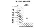
図2に、図1におけるP部の詳細断面図を示す。同図に示すように、Oリング溝24の外周部には、全周にわたってトラップ収納溝41が設けられている。このトラップ収納溝41の内部には、空気中の不純物を吸着する不純物トラップ42が収納されている。
【0023】
F2レーザ1のパワーを減衰させたり光路空間21内部の光学部品を汚損したりする不純物のうち、酸素及び水蒸気はOリング25を透過することがあり、このような不純物を含んだ空気がOリング25に触れないようにする必要がある。そのため、不純物トラップ42としては、1)酸素を吸着するジルコニア系合金やニッケル系触媒、2)水蒸気を吸着するゼオライト(例えばモレキュラーシーブ)等が有効である。
即ち、酸素又は水蒸気のうち、少なくともいずれか1種類を吸着する不純物トラップ42を、Oリング溝24より外気側に設けたトラップ収納溝41の内部に収納する。これにより、Oリング溝24内のOリング25に触れる空気中に含まれる不純物が、吸着されて除去される。従って、不純物がOリング25に触れることが少なくなり、Oリング25を透過して光路空間21内部に混入する不純物の量が少なくなる。
尚、酸素及び水蒸気の双方を除去するように、少なくとも2種類以上の不純物トラップ42,42をトラップ収納溝41の内部に収納するのが望ましい。
【0024】
図3に、Oリングに触れる不純物を減少させる手段の他の例として、図1のP部詳細断面図を示す。同図に示すように、Oリング溝24の外周部には、第2のOリング溝45が全周にわたって設けられ、その内部には第2のOリング46が嵌挿されている。これにより、Oリング25と第2のOリング46との間に閉じ込められた空気のみが、Oリング25に触れることになる。従って、不純物がOリング25に触れることが少なくなり、Oリング25を透過して光路空間21内部に混入する不純物の量が少なくなる。
【0025】
図4に、Oリング溝24近傍のトラップ収納溝41の他の例として、図1のP部詳細断面図を示す。同図に示すように、Oリング溝24の外周部には、不純物トラップ42を収納したトラップ収納溝41が設けられている。そして、このトラップ収納溝41の外周部には、第2のOリング溝45が全周に設けられ、その内部には第2のOリング46が嵌挿されている。
このように、不純物トラップ42の外周側を第2のOリング46で封止しているので、不純物トラップ42が、Oリング25と第2のOリング46との間に閉じ込められた空気から不純物を吸着すれば、新たに不純物を含んだ空気がOリング25に触れることがない。従って、不純物トラップ42が除去しなければならない不純物の量が、第2のOリング46が存在しない場合に比べて少なく、不純物トラップ42の不純物吸着能力が長期間にわたって保たれる。その結果、不純物トラップ42を交換する等のメンテナンスの間隔を延ばすことが可能となる。
【0026】
図5に、図1のQ部詳細断面図を示す。同図において、カバー22の外周面上には、Oリング溝24が全周にわたって設けられ、その内部にはOリング25が嵌挿されている。そして、Oリング溝24の外気側(図中右側)には、トラップ収納溝41が全周にわたって設けられ、その内部には不純物トラップ42が収納されている。
このように、カバー22とウィンドウホルダ6との接続部に設けられたOリング溝24の外気側にも、不純物を除去する不純物トラップ42を備えており、ここから光路空間21に不純物が混入するのを防止している。
【0027】
さらには、このような不純物トラップ42の配置は、カバー22,22と、狭帯域化ボックス14及びウィンドウホルダ6との接続部をそれぞれ密封するOリング25,25の外気側のみに限られるものではない。即ち、光路カバー13,14,22を封止する、図示しない他のOリングに関しても同様に、その外気側に不純物トラップ42を配置するのがよい。これにより、光路空間21への不純物の混入が防止されるので、不純物によるパワーの減衰や光学部品の汚損が起きにくく、真空紫外レーザを長期にわたって安定に稼働させることが可能である。
【0028】
また、図1において、光路空間21には、窒素(N2)等の不活性ガスが充填されたパージボンベ26と、パージバルブ27と、パージ配管30とを有するパージ手段が、パージ口39を介して接続されている。
このパージ配管30のパージ口39近傍には、不純物を除去するトラップ装置47が接続されている。不活性ガスは、このトラップ装置47を通過して光路空間21内に導入されるので、不純物が除去された清浄な不活性ガスをパージできる。
【0029】
上述したように、酸素、水蒸気又は有機物等の不純物が光路空間21に混入すると、パワー減衰や光学部品の汚損の原因となる。そのため、トラップ装置47としては、上記の1)酸素を吸着するジルコニア系合金やニッケル系触媒、2)水蒸気を吸着するゼオライトに加え、3)有機物を吸着する活性炭等の不純物トラップ42を密閉容器内に収納したものが有効である。
また、これらのトラップ装置47に加え、水蒸気を除去するトラップ装置として、4)低温トラップ装置も有効である。低温トラップ装置は液体窒素等で冷却する低温槽を備えており、特に水蒸気を凍らせて効率的に吸着することができる。また、低温槽の温度を上げることにより、吸着した水蒸気を外気に排出することができるので、長期間にわたって水蒸気の吸着能力を保つことが可能である。
【0030】
これらのトラップ装置47のうち、少なくともいずれか1種類をパージ配管30に接続することにより、パージ配管30やパージボンベ26中の不活性ガスに含まれる不純物が、光路空間21の内部に混入するのを防止できる。尚、酸素、水蒸気及び有機物をすべて除去できるように、上記1)〜3)の不純物トラップ42を同一の密閉容器内に収納するか、又は酸素、水蒸気及び有機物をそれぞれ除去可能な各トラップ装置47を直列に接続するのが最も好ましい。
【0031】
以上説明したように、光路カバー(本実施形態によれば、波長ボックス13、狭帯域化ボックス14、及びカバー22)で覆われた光路空間21は、Oリング25で密封されている。そして、本実施形態によれば、このOリング25が嵌挿されたOリング溝24の外気側にトラップ収納溝41を設け、このトラップ収納溝41の内部に空気中の不純物(実施形態によれば、酸素又は水蒸気の少なくともいずれか1つ)を除去する不純物トラップ42(実施形態によれば、ジルコニア系合金、ニッケル系触媒、又はゼオライト)を収納している。
これにより、Oリング25に接触する空気から酸素又は水蒸気を除去しているので、これらがOリング25を透過して光路空間21の内部に混入することが少ない。従って、不純物によるパワーの減衰や光路空間21内の光学部品の汚損が起きにくい。
さらに、酸素及び水蒸気の双方を吸着する不純物トラップ42,42を、不純物収納溝41の内部に収納しているので、パワーの減衰や光学部品の汚損を招く不純物が光路空間21内に殆んど混入せず、真空紫外レーザを長期にわたって安定に稼働させることができる。
【0032】
また、Oリング25,46を二重にしているので、Oリング25と第2のOリング46との間に閉じ込められた空気のみが、Oリング25に触れることになり、Oリング25に触れる不純物の量が少なくなる。従って、Oリング25を透過する不純物が少なくなり、光路空間21内に不純物が混入するのを防止することができる。
【0033】
また、Oリング25,46を二重にして、その間に不純物トラップ42を配置しているので、Oリング25と第2のOリング46との間に閉じ込められた空気のみが、Oリング25に触れることになる。不純物トラップ42は、この閉じ込められた空気から不純物を吸着すれば、新たに不純物を含んだ空気がOリング25に触れることがない。従って、除去しなければならない不純物の量が、第2のOリング46が存在しない場合に比べて少なく、不純物トラップ42が、長期間にわたって不純物吸着能力を保つことが可能である。その結果、不純物トラップ42を交換する必要がなく、メンテナンス間隔を延ばすことが可能となる。
【0034】
また、トラップ装置47により、光路空間21内にパージする不活性ガスから、不純物を除去している。これにより、パージ配管30の内部に付着したり、パージボンベ26に混入したりしている不純物が、光路空間21内に混入することが少なくなる。従って、不純物によるパワーの減衰や光学部品の汚損が起きにくく、真空紫外レーザを長期にわたって、安定に稼働させることが可能である。
また、パージボンベ26中の不活性ガスの純度を上げることなしに、清浄な不活性ガスを光路空間21内に導入可能であり、パージ時の不活性ガスの消費コストが低減される。
さらには、トラップ装置47をパージ口39近傍に配置しているので、トラップ装置47と光路空間21との距離が短い。そのため、トラップ装置47と光路空間21との間のパージ配管30中に付着している不純物が少なく、この不純物が光路空間21内に混入する量を少なくすることができる。
【0035】
また、レーザ光11のパワーの減衰や光学部品の汚損の原因として最も大きな影響を及ぼす不純物である、酸素、水蒸気、又は有機物の少なくともいずれか1つを不活性ガスから除去するようにしている。これにより、パワーの減衰や光学部品の汚損を効率的に防止できる。さらに、これらの不純物すべてを除去することにより、真空紫外レーザを長期にわたって安定に稼働させることが可能である。
尚、以上の説明では、不純物トラップ42を収納するトラップ収納部として、トラップ収納溝41を例にとって説明したが、このようなトラップ収納部は、必ずしも溝の形状を有している必要はない。また、トラップ収納部が、Oリング25の外気側を全周にわたって取り巻いている必要はない。
【0036】
次に、第2実施形態を説明する。第2実施形態に係るF2レーザ1の外観は、図7に示したものと同様であり、重複する説明は省略する。
【0037】
第2実施形態では、図7に示したF2レーザ1において、光路空間21を密封するためのOリング25に代えて、光路カバー13,14,22に設けられたOリング溝24の内部に金属ガスケット43を嵌挿している。図6に、図1におけるP部と略同一箇所の詳細断面図を示す。金属ガスケット43は、例えばアルミニウムや銅等の軟らかな金属で構成されている。同図に示すように、この金属ガスケット43を、Oリング溝24と狭帯域化ボックス14の側面との間で圧迫することによって潰し、光路空間21を密封している。
【0038】
即ち、本実施形態によれば、光路空間21を覆う光路カバー13,14,22を、金属ガスケット43で密封している。この金属ガスケット43は、酸素、水蒸気、或いは有機物等の不純物を透過することが少ないので、光路空間21にこれらの不純物が混入することが少ない。従って、不純物によるパワーの減衰や光学部品の汚損が起きにくく、真空紫外レーザを長期にわたって、安定に稼働させることが可能である。
【0039】
以上説明したように、本発明によれば、光路空間21を覆う光路カバー13,14,22を密封するOリング25に、空気中の不純物が触れるのを防止している。これにより、Oリング25を空気中の不純物が透過することが少なくなるため、光路空間21内への不純物の混入を防止できる。従って、レーザ光11のパワーの減衰が少なく、また、光路空間21内の光学部品の汚損も少ない。
また、光路空間21をパージするパージ配管30の途中にトラップ装置47を設け、不活性ガス中の不純物を除去している。これにより、常に清浄な不活性ガスが光路空間21にパージされるので、光路空間21内の不純物を減少させることができる。従って、レーザ光11のパワーの減衰が少なく、また、光路空間21内の光学部品の汚損も少ない。
【0040】
また、光路空間21を覆う光路カバー13,14,22を、金属ガスケット43で密封しているので、不純物がこの金属ガスケット43を透過することが少なく、光路空間21に混入する量も少ない。従って、レーザ光11のパワーの減衰が少なく、また、光路空間21内の光学部品の汚損も少ない。
【0041】
尚、各実施形態では、真空紫外レーザとしてグレーティング33によって狭帯域化されたF2レーザを例にとって説明したが、狭帯域化のための波長選択素子は、グレーティング33に限らず、例えばエタロンや分散プリズムでもよい。さらに、狭帯域化されたレーザに限られるものではなく、狭帯域化ユニット10に代えてリアミラー等を配置してもよい。
また、本発明はF2レーザに限らず、前述したArFエキシマレーザ等の真空紫外光を発振する真空紫外レーザすべてにおいて適用可能である。即ち、放電以外の手段(例えばレーザビーム等)によって励起されるガスレーザや、ガスレーザ以外の真空紫外レーザに対しても適用可能である。
【図面の簡単な説明】
【図1】第1実施形態に係るF2レーザの構成断面図。
【図2】図1のP部詳細断面図。
【図3】図1のP部詳細断面図。
【図4】図1のP部詳細断面図。
【図5】図1のQ部詳細断面図。
【図6】第2実施形態に係る金属ガスケットの詳細断面図。
【図7】従来技術に係るF2レーザの構成断面図。
【符号の説明】
1:F2レーザ、2:レーザチャンバ、3:波長測定装置、4:レーザコントローラ、5,5:放電電極、6:ウィンドウホルダ、7:フロントウィンドウ、8:フロントミラー、9:リアウィンドウ、10:狭帯域化ユニット、11A:サンプル光、11:レーザ光、12:ビームスプリッタ、13:波長ボックス、14:狭帯域化ボックス、15:加工機、21:光路空間、22:カバー、23:パージコントローラ、24:Oリング溝、25:Oリング、26:パージボンベ、28:真空ポンプ、29:真空バルブ、30:パージ配管、31:真空配管、32:プリズム、33:グレーティング、34:ビームスプリッタ、35:パワー検出器、36:波長検出器、41:トラップ収納溝、42:不純物トラップ、43:金属ガスケット、45:第2のOリング溝、46:第2のOリング、47:トラップ装置。[0001]
BACKGROUND OF THE INVENTION
The present invention relates to a vacuum ultraviolet laser that oscillates laser light in the vacuum ultraviolet region.
[0002]
[Prior art]
Conventionally, a vacuum ultraviolet laser that oscillates a vacuum ultraviolet light having a wavelength of about 20 nm to 200 nm, which is called a vacuum ultraviolet region, is known, such as an ArF laser (193 nm) and an F2 laser (157 nm). Such a vacuum ultraviolet laser is mainly used for precision processing such as laser lithography.
[0003]
FIG. 7 shows a configuration diagram of an F2 laser according to the prior art, and the prior art will be described with reference to FIG.
In the figure, an
[0004]
Inside the
The
At this time, a part of the laser beam 11 emitted from the front mirror 8 is sampled by the wavelength measuring device 3, and the wavelength characteristic and power are measured.
[0005]
The oscillated laser beam 11 is vacuum ultraviolet light and is absorbed very well by oxygen and water vapor in the air, so that the power is attenuated by passing through the air. In addition, when oxygen is irradiated with vacuum ultraviolet light, ozone (O3) is generated, which causes optical components to be contaminated. Further, when an organic substance contained in the air is mixed into the optical path, the organic substance adheres to the optical component, causing the optical component to be contaminated.
In order to prevent such power attenuation and optical component contamination, a technique is known in which air is blocked from the optical path of the laser beam 11 so that impurities such as oxygen, water vapor, and organic substances are not mixed.
That is, as shown in the figure, the optical path of the laser beam 11 includes a
[0006]
[Problems to be solved by the invention]
However, the prior art has the following problems.
[0007]
That is, as described above, since the laser beam 11 is absorbed by impurities, if impurities are mixed in the purged inert gas, the power is attenuated even if the amount is very small. In order to prevent this, the purity of the inert gas filled in the
[0008]
Further, in the prior art, even if impurities such as moisture and organic matter adhere to the inside of the
[0009]
Further, since the O-
[0010]
The present invention has been made paying attention to the above-mentioned problems, and an object of the present invention is to provide a vacuum ultraviolet laser that prevents attenuation of oscillated laser light and contamination of optical components.
[0011]
[Means, actions and effects for solving the problems]
In order to achieve the above object, the first invention provides an optical path cover that covers an optical path space through which a laser beam passes, an O-ring groove provided in the optical path cover, and an O-ring inserted into the O-ring groove. with the door, in a vacuum ultraviolet laser for oscillating the laser light in the vacuum ultraviolet region, said trap housing portion to the outside air is provided than O-ring groove, in the interior of the trap housing portion, at least one of oxygen and water vapor Contains an impurity trap to be removed.
[0012]
According to the first invention, comprising an impurity trap to the outside air side of the O-ring groove, before the air contacts the O-ring, and removing at least one impurity of oxygen and water vapor from the air by the impurity trapping . As a result, at least one of oxygen and water vapor contained in the air in contact with the O-ring is reduced, so that oxygen or water vapor can pass through the O-ring and enter the optical path space or the inside of the laser chamber. Less. Accordingly, power attenuation due to oxygen or water vapor and optical component contamination are unlikely to occur, and the vacuum ultraviolet laser can be stably operated over a long period of time.
[0015]
DETAILED DESCRIPTION OF THE INVENTION
Hereinafter, embodiments according to the present invention will be described in detail with reference to the drawings. In each embodiment, the same reference numerals are given to the same elements as those used in the description of the above-described prior art and the drawings used in the description of the previous embodiment, and a duplicate description is omitted. To do.
[0016]
In the following embodiment, an F2 laser will be described as an example of a vacuum ultraviolet laser.
First, a first embodiment will be described with reference to FIG. FIG. 1 is a sectional view showing the configuration of the F2 laser according to this embodiment. In this figure, an
[0017]
The
Inside the
In general, in such an
[0018]
The laser beam 11 oscillated in the
The band narrowing unit 10 includes, for example, two prisms 32 and 32 and a grating 33 which is a wavelength selection element. Of the laser light 11 expanded by the prisms 32, 32, only the laser light 11 having a predetermined wavelength characteristic is folded back in the same direction as the incident light by the grating 33 and narrowed.
The narrow-band laser beam 11 is emitted from the narrow-band unit 10, passes through the
[0019]
The wavelength measuring device 3 has a
A part of the
The band-narrowing unit 10 and the wavelength measuring device 3 are housed inside a band-narrowing
[0020]
The following description will be given only for the rear side (
A
[0021]
The
That is, an O-
[0022]
FIG. 2 is a detailed cross-sectional view of a P portion in FIG. As shown in the figure, a
[0023]
Among the impurities that attenuate the power of the
That is, the
It is desirable to store at least two types of impurity traps 42 and 42 in the
[0024]
FIG. 3 is a detailed cross-sectional view of a portion P in FIG. 1 as another example of means for reducing impurities that touch the O-ring. As shown in the figure, a second O-
[0025]
FIG. 4 is a detailed cross-sectional view of a P portion in FIG. 1 as another example of the
As described above, since the outer peripheral side of the
[0026]
FIG. 5 shows a detailed cross-sectional view of a Q portion in FIG. In the figure, an O-
As described above, an
[0027]
Furthermore, the arrangement of the
[0028]
In FIG. 1, purge means having a
A
[0029]
As described above, when impurities such as oxygen, water vapor, or organic matter are mixed in the
In addition to these
[0030]
By connecting at least one of these
[0031]
As described above, the
As a result, oxygen or water vapor is removed from the air in contact with the O-
Further, since the impurity traps 42 and 42 that adsorb both oxygen and water vapor are accommodated in the
[0032]
Further, since the O-
[0033]
In addition, since the O-
[0034]
Further, the
Further, it is possible to introduce clean inert gas into the
Furthermore, since the
[0035]
In addition, at least one of oxygen, water vapor, and organic matter, which is the impurity that has the greatest influence on the attenuation of the power of the laser beam 11 and the contamination of the optical components, is removed from the inert gas. As a result, power attenuation and optical component contamination can be efficiently prevented. Furthermore, by removing all these impurities, the vacuum ultraviolet laser can be operated stably over a long period of time.
In the above description, the
[0036]
Next, a second embodiment will be described. The appearance of the
[0037]
In the second embodiment, in the
[0038]
That is, according to the present embodiment, the optical path covers 13, 14, and 22 covering the
[0039]
As described above, according to the present invention, impurities in the air are prevented from touching the O-
In addition, a
[0040]
Further, since the optical path covers 13, 14, and 22 covering the
[0041]
In each of the embodiments, the F2 laser narrowed by the grating 33 as an example of the vacuum ultraviolet laser has been described as an example. However, the wavelength selection element for narrowing the band is not limited to the grating 33, for example, an etalon or a dispersion prism. But you can. Furthermore, the laser is not limited to a narrow band laser, and a rear mirror or the like may be disposed instead of the narrow band unit 10.
The present invention is not limited to the F2 laser, but can be applied to all vacuum ultraviolet lasers that oscillate vacuum ultraviolet light, such as the ArF excimer laser described above. That is, the present invention can also be applied to a gas laser excited by means other than discharge (for example, a laser beam) or a vacuum ultraviolet laser other than a gas laser.
[Brief description of the drawings]
FIG. 1 is a structural cross-sectional view of an F2 laser according to a first embodiment.
FIG. 2 is a detailed cross-sectional view of a portion P in FIG.
3 is a detailed cross-sectional view of a portion P in FIG.
4 is a detailed cross-sectional view of a P part in FIG. 1. FIG.
5 is a detailed cross-sectional view of a portion Q in FIG.
FIG. 6 is a detailed sectional view of a metal gasket according to a second embodiment.
FIG. 7 is a structural cross-sectional view of a conventional F2 laser.
[Explanation of symbols]
1: F2 laser, 2: laser chamber, 3: wavelength measuring device, 4: laser controller, 5, 5: discharge electrode, 6: window holder, 7: front window, 8: front mirror, 9: rear window, 10: Narrowband unit, 11A: sample light, 11: laser light, 12: beam splitter, 13: wavelength box, 14: narrowband box, 15: processing machine, 21: optical path space, 22: cover, 23: purge controller 24: O-ring groove, 25: O-ring, 26: purge cylinder, 28: vacuum pump, 29: vacuum valve, 30: purge pipe, 31: vacuum pipe, 32: prism, 33: grating, 34: beam splitter, 35 : Power detector, 36: Wavelength detector, 41: Trap storage groove, 42: Impurity trap, 43: Metal gasket 45: second O-ring groove, 46: second O-ring, 47: trap device.
Claims (1)
前記Oリング溝(24)よりも外気側にトラップ収納部(41)を設け、
このトラップ収納部(41)の内部に、酸素及び水蒸気の少なくともいずれか一方を除去する不純物トラップ(42)を収納した
ことを特徴とする真空紫外レーザ(1)。An optical path cover (13, 14, 22) covering the optical path space (21) through which the laser beam (11) passes, an O-ring groove (24) provided in the optical path cover (13, 14, 22), and an O-ring groove A vacuum ultraviolet laser (1) comprising an O-ring (25) inserted into the inside of (24) and oscillating laser light (11) in the vacuum ultraviolet region;
A trap storage part (41) is provided on the outside air side of the O-ring groove (24),
A vacuum ultraviolet laser (1) characterized in that an impurity trap (42) for removing at least one of oxygen and water vapor is housed in the trap housing section (41).
Priority Applications (1)
| Application Number | Priority Date | Filing Date | Title |
|---|---|---|---|
| JP04720299A JP4007708B2 (en) | 1999-02-24 | 1999-02-24 | Vacuum ultraviolet laser |
Applications Claiming Priority (1)
| Application Number | Priority Date | Filing Date | Title |
|---|---|---|---|
| JP04720299A JP4007708B2 (en) | 1999-02-24 | 1999-02-24 | Vacuum ultraviolet laser |
Publications (2)
| Publication Number | Publication Date |
|---|---|
| JP2000252554A JP2000252554A (en) | 2000-09-14 |
| JP4007708B2 true JP4007708B2 (en) | 2007-11-14 |
Family
ID=12768567
Family Applications (1)
| Application Number | Title | Priority Date | Filing Date |
|---|---|---|---|
| JP04720299A Expired - Fee Related JP4007708B2 (en) | 1999-02-24 | 1999-02-24 | Vacuum ultraviolet laser |
Country Status (1)
| Country | Link |
|---|---|
| JP (1) | JP4007708B2 (en) |
Families Citing this family (3)
| Publication number | Priority date | Publication date | Assignee | Title |
|---|---|---|---|---|
| JP4052457B2 (en) * | 2003-01-29 | 2008-02-27 | 三菱重工業株式会社 | Microwave excited hydrogen ultraviolet light lamp and method of using an optical device using the ultraviolet light lamp |
| JP5257287B2 (en) * | 2009-07-27 | 2013-08-07 | 三菱電機株式会社 | Laser equipment |
| CN111801854B (en) * | 2018-04-23 | 2022-10-21 | 极光先进雷射株式会社 | Laser cavity, method for manufacturing sealing member, and method for manufacturing electronic device |
-
1999
- 1999-02-24 JP JP04720299A patent/JP4007708B2/en not_active Expired - Fee Related
Also Published As
| Publication number | Publication date |
|---|---|
| JP2000252554A (en) | 2000-09-14 |
Similar Documents
| Publication | Publication Date | Title |
|---|---|---|
| US6028310A (en) | Linear cavity laser system for intracavity laser spectroscopy | |
| US4229709A (en) | Laser device | |
| JP4803176B2 (en) | Solid state laser equipment | |
| US20030137672A1 (en) | Wavelength detecting apparatus, laser apparatus, and wavelength detecting method | |
| CN109073463B (en) | Wavelength detection device | |
| US6490305B2 (en) | Beam delivery system for molecular fluorine (F2) laser | |
| CA2203780C (en) | Ultra-sensitive detection of contaminants in gas via intracavity laser spectroscopy (ils) | |
| KR20010089431A (en) | Optical device, exposure system, and laser beam source, and gas feed method, exposure method, and device manufacturing method | |
| JP2006504252A (en) | Laser closed-loop purge system | |
| US20040179187A1 (en) | Method and apparatus for implementing an afterglow emission spectroscopy monitor | |
| JP4007708B2 (en) | Vacuum ultraviolet laser | |
| US20030219057A1 (en) | DUV and VUV laser with on-line pulse energy monitor | |
| JP2000124534A (en) | ArF EXCIMER LASER AND BAND NARROWING MODULE THEREOF | |
| JP4758345B2 (en) | Vacuum ultraviolet radiation detection apparatus and method | |
| JP3360097B2 (en) | Vacuum ultraviolet optical device | |
| US6627843B2 (en) | Casing for laser device, production method and cleaning method of the same | |
| WO2013153704A1 (en) | Laser device | |
| JP2000124121A (en) | Optical device, aligner, lens-barrel, connecting device, case and lens-barrel end shield | |
| JP2003163407A (en) | Optical semiconductor device | |
| JP2003344601A (en) | Device and method for cleaning optical element and method for manufacturing it | |
| JP2000236125A (en) | Vacuum ultraviolet laser | |
| JP2000106463A (en) | Wavelength calibration method and system for excimer laser | |
| JP2003258337A (en) | Cleaning method for cabinet for laser apparatus | |
| JP4462152B2 (en) | ICP emission analyzer | |
| JP2001284685A5 (en) |
Legal Events
| Date | Code | Title | Description |
|---|---|---|---|
| A621 | Written request for application examination |
Free format text: JAPANESE INTERMEDIATE CODE: A621 Effective date: 20050225 |
|
| A131 | Notification of reasons for refusal |
Free format text: JAPANESE INTERMEDIATE CODE: A131 Effective date: 20070606 |
|
| A521 | Written amendment |
Free format text: JAPANESE INTERMEDIATE CODE: A523 Effective date: 20070727 |
|
| TRDD | Decision of grant or rejection written | ||
| A01 | Written decision to grant a patent or to grant a registration (utility model) |
Free format text: JAPANESE INTERMEDIATE CODE: A01 Effective date: 20070828 |
|
| A61 | First payment of annual fees (during grant procedure) |
Free format text: JAPANESE INTERMEDIATE CODE: A61 Effective date: 20070828 |
|
| FPAY | Renewal fee payment (event date is renewal date of database) |
Free format text: PAYMENT UNTIL: 20100907 Year of fee payment: 3 |
|
| R150 | Certificate of patent or registration of utility model |
Free format text: JAPANESE INTERMEDIATE CODE: R150 |
|
| FPAY | Renewal fee payment (event date is renewal date of database) |
Free format text: PAYMENT UNTIL: 20100907 Year of fee payment: 3 |
|
| FPAY | Renewal fee payment (event date is renewal date of database) |
Free format text: PAYMENT UNTIL: 20110907 Year of fee payment: 4 |
|
| FPAY | Renewal fee payment (event date is renewal date of database) |
Free format text: PAYMENT UNTIL: 20110907 Year of fee payment: 4 |
|
| FPAY | Renewal fee payment (event date is renewal date of database) |
Free format text: PAYMENT UNTIL: 20120907 Year of fee payment: 5 |
|
| FPAY | Renewal fee payment (event date is renewal date of database) |
Free format text: PAYMENT UNTIL: 20120907 Year of fee payment: 5 |
|
| FPAY | Renewal fee payment (event date is renewal date of database) |
Free format text: PAYMENT UNTIL: 20130907 Year of fee payment: 6 |
|
| S111 | Request for change of ownership or part of ownership |
Free format text: JAPANESE INTERMEDIATE CODE: R313113 |
|
| R350 | Written notification of registration of transfer |
Free format text: JAPANESE INTERMEDIATE CODE: R350 |
|
| R250 | Receipt of annual fees |
Free format text: JAPANESE INTERMEDIATE CODE: R250 |
|
| R250 | Receipt of annual fees |
Free format text: JAPANESE INTERMEDIATE CODE: R250 |
|
| LAPS | Cancellation because of no payment of annual fees |