JP4006940B2 - Wristband automatic payment machine - Google Patents
Wristband automatic payment machine Download PDFInfo
- Publication number
- JP4006940B2 JP4006940B2 JP2000333963A JP2000333963A JP4006940B2 JP 4006940 B2 JP4006940 B2 JP 4006940B2 JP 2000333963 A JP2000333963 A JP 2000333963A JP 2000333963 A JP2000333963 A JP 2000333963A JP 4006940 B2 JP4006940 B2 JP 4006940B2
- Authority
- JP
- Japan
- Prior art keywords
- card
- exit
- wristband
- shutter
- exit card
- Prior art date
- Legal status (The legal status is an assumption and is not a legal conclusion. Google has not performed a legal analysis and makes no representation as to the accuracy of the status listed.)
- Expired - Fee Related
Links
Images


Description
【0001】
【発明の属する技術分野】
この発明は、リストバンド自動精算機に関する。
【0002】
【従来の技術】
たとえば、いわゆる健康ランドのような24時間営業の利用施設等では、営業中であっても施設利用者の利用を妨げずにリストバンド自動精算機のメンテナンスができることが要請される。そこで、本願出願人は、特願2000−200309号等において、前面扉側および背面扉側の双方から各種構成機器を容易にメンテナンスできるリストバンド自動精算機を提案するに至った。このリストバンド自動精算機は、利用者の施設退場時に退場カードを発行する退場カード発行ユニットを備えている。
【0003】
この退場カード発行ユニットは、退場カードに退場時間等の所定データを書き込んで前面扉の退場カード取出口へと搬送する搬送機能を備えたカードリーダと、予め貯留している退場カードをこのカードリーダに搬出するカード搬出装置とから構成されている。以下、このような退場カード発行ユニットを備えた従来のリストバンド自動精算機について説明する。
【0004】
まず、リストバンド自動精算機の全体構成について説明する。ここで、図7は、リストバンド自動精算機を示す背面斜視図、図8は、リストバンド自動精算機を示す正面斜視図、図9は、リストバンド自動精算機を示す正面図、図10は、リストバンドを示す平面図である。各構成機器を収納する本体ケース1は、開閉自在に設けられた前面扉2および背面扉3と棚4を備えている。なお、背面扉3に設けられた開口部3aは、背面扉3を閉じた状態でも、リストバンド回収ボックス35を本体ケース1の外部に取り出せるようにしたものである。
【0005】
リストバンド5は、タグ部5aとバンド部5bとキー5cとからなり、このタグ部5aには、電池不要のEEPROMからなるIDタグメモリが内蔵されている。すなわち、このタグ部5aに施設利用者の個人情報(たとえば、ロッカー番号等)が書き込まれている。リストバンド回収ユニット10は、精算時に投入されるリストバンド5を回収するためのものであり、前面扉2側および背面扉3側の両方向にスライド移動自在に形成され、前面扉2側および背面扉3側の双方からメンテナンス作業をできるように形成されている。
【0006】
背面扉3の内面に設けられたリストバンド一時保留ユニット40は、リストバンド回収ユニット10によって回収されたリストバンド5を、リストバンド返却口96またはリストバンド回収ボックス35に振り分ける際に一時的に保留するためのものである。背面扉3の内面に設けることにより、前面扉2を閉めたままでも、コインメカニズム90およびコインホッパ60のメンテナンスができるようになっている。
【0007】
コインホッパ60は、釣銭用コインを収納し必要時に払い出すためのものであり、前面扉2側および背面扉3側の両方向にスライド移動自在に形成され、前面扉2側および背面扉3側の双方からメンテナンス作業をできるように形成されている。なお、コイン投入口92から投入されたコインは、投入コイン回収ボックス52に回収され、売り上げ締め作業時に払い出したコインは、コインホッパ用回収ボックス53に回収されるようになっている。
【0008】
紙幣識別装置70は、紙幣挿入口93から支払われた紙幣を識別するためのものであり、前面扉2側および背面扉3側の両方向にスライド移動自在に形成され、前面扉2側および背面扉3側の双方からメンテナンス作業をできるように形成されている。また、この紙幣識別装置70は、鉛直方向を軸にして所定角度、回動自在に形成されている。領収書発行ユニット80は、精算後に領収書を発行するためのものであり、前面扉2側および背面扉3側の両方向にスライド移動自在に形成されているとともに、本体部の前部を支点にして、後部を持ち上げられるように形成されている。
【0009】
退場カード発行ユニット88は、精算後に退場カードを発行するためのものであり、前面扉2側および背面扉3側の両方向にスライド移動自在に形成されている。コインメカニズム90は、コイン投入口92から投入されたコインを識別するためのものである。
【0010】
また、前面扉2には、リストバンド挿入口91、コイン投入口92、紙幣挿入口93、紙幣返却口94、コイン返却口95、リストバンド返却口96、操作部たるタッチパネルディスプレイ97、操作要領等を発声するスピーカ98、クレジットカード挿入口99、退場カード取出口100、領収書取出口101、利用者を検知し、精算手続待機状態とするための人体センサ102、クレジットカードリーダ105等を備えている。また、本体ケース1内には、装置全体の制御を行うコントロールボックス103、コントロールボックス103に各種の入力操作を行うキーボード104、無停電式の電源装置106、ドアスイッチ107、盗難防止ブザースイッチ108等を備えている。
【0011】
つぎに退場カード発行ユニット88について、図11に基づいてさらに詳しく説明する。ここで、図11は、従来の退場カード発行ユニットのカードリーダを模式的に示す断面図である。退場カード発行ユニット88は、退場カード(以下、カードと記す)198に退場時間等の所定データを書き込んで前面扉2の退場カード取出口100へと搬送する搬送機能を備えたカードリーダ300と、予め貯留しているカード198をこのカードリーダ300に搬出するカード搬出装置170とから構成されている。
【0012】
カードリーダ300内では、図示しない駆動モータによって駆動される搬送ローラ302によりカード198が搬送され、その搬送状態はセンサ301によって検知されるようになっている。通路303は、カード198の厚み方向に対応する寸法が受け口からカード搬出口に向かって次第に小さくなるように形成され、搬送ローラ302を通過したカード198の反りを抑制しながら、カード搬出口に向かって案内するように形成されている。
【0013】
カード198の搬送路終端部は、ソレノイド304によって駆動されるシャッタ305によって開閉されるようになっている。搬送されたカード198は、板ばね307の押圧力による摩擦によって停止するようになっており、カードリーダ300からカード198が抜き取られたか否かは、センサ306によって検知されるようになっている。
【0014】
【発明が解決しようとする課題】
しかしながら、従来のリストバンド自動精算機の退場カード発行ユニット88は、カードリーダ300のカード搬送機能によってカード198を退場カード取出口100に搬送しているため、カード198にデータを書き込む必要がない場合には、当該カード搬送のためにのみカードリーダ300を使用していることとなり、コスト高となっていた。
【0015】
また、このようなデータの書き込み機能を必要としない場合には、上記カード搬出装置170を前面扉2の直後に配置し、その搬出機能によって退場カード取出口100にカード198を搬送するように構成することも可能であるが、その場合、カード搬出装置170が前面扉2側に偏って配置されるため、背面扉3側からのメンテナンスがしにくくなってしまうという課題があった。
【0016】
また、カード搬出装置170に、カード198の抜き取り検知手段や搬送検知手段、カード停止手段、カード逆入れ防止手段(シャッタ機構)等を別途設ける必要があり、これらを設けると、顧客側の運用変更により再度カードリーダ300を使用する必要が生じた場合に、カードリーダ300との互換性の保持が困難になってしまうという課題もあった。
【0017】
この発明は、上記に鑑みてなされたものであって、カード搬出装置から搬出されたカードを簡易な構成によって確実に搬送・搬出できるとともに、カードリーダとの互換性を容易に保持でき、顧客側の運用変更に柔軟かつ低コストで対応できる退場カード発行ユニットを備えたリストバンド自動精算機を提供することを目的とする。
【0018】
また、この発明は、簡易な構成によってカードの搬送・抜き取り状態を確実に検知できるとともに、カードの逆入れを有効に防止できる退場カード発行ユニットを備えたリストバンド自動精算機を提供することを目的とする。
【0019】
【課題を解決するための手段】
上述の目的を達成するために、この発明の請求項1にかかるリストバンド自動精算機は、精算後に退場カードを発行する退場カード発行ユニットを備えたリストバンド自動精算機において、前記退場カード発行ユニットは、前記退場カードを退場カード取出口へ搬送手段によって搬送するカード搬送装置と、予め貯留している前記退場カードを前記カード搬送装置に搬出するカード搬出装置とを備え、前記カード搬送装置は、退場カードを案内する案内溝を有したガイドレールを搬送方向と平行に一対備え、前記一対のガイドレールは、カード取出開口部に近づくにしたがって互いに近接するとともに、当該カード取出開口部直前において互いの前記案内溝どうしが連通するように形成したものである。これにより、反りの生じた退場カードを徐々に整形して反りのない状態でカード取出開口部から送出でき、カード詰まり等を防止できる。
【0020】
また、この発明の請求項2にかかるリストバンド自動精算機は、カード搬送装置は、退場カード取出口からの退場カードの逆入れを防止するために、当該退場カード取出口と搬送手段終端部との間にシャッタを備え、前記シャッタは、前記搬送手段を経た前記退場カードの進入時の当接により姿勢を変化させて当該退場カードの通路を開けるとともに、当該退場カードの通過後の当接解除により自重で姿勢を変化させて当該退場カードの通路を閉じるように形成したものである。これにより、きわめて簡易な構成にて退場カード取出口からの退場カードの逆入れを防止でき、カード詰まり等を防止できる。
【0021】
また、この発明の請求項3にかかるリストバンド自動精算機は、シャッタは、搬送手段を経た退場カードの通過途中の当接により姿勢を変化させて当該退場カードの通路を閉じるように形成したものである。これにより、退場カードの通過途中においても、退場カードの逆入れを防止でき、カード詰まり等を防止できる。
【0022】
また、この発明の請求項4にかかるリストバンド自動精算機は、退場カードの通過を検知するセンサ手段を、搬送手段終端部とシャッタとの間に配設したものである。これにより、一つのセンサ手段により、退場カードの搬送終了と抜き取りとを確実に検知できる。
【0024】
また、この発明の請求項5にかかるリストバンド自動精算機は、カード取出開口部には、搬出された退場カードに当接し当該退場カードの静電気を除去する除電ブラシを備えたものである。これにより、帯電したカードの静電気を除去できるとともに、搬送直後のカードが慣性力でカード取出開口部から飛び出すのを防止できる。
【0025】
【発明の実施の形態】
以下、この発明にかかるリストバンド自動精算機の実施の形態につき図面を参照しつつ詳細に説明する。なお、この実施の形態によりこの発明が限定されるものではない。
【0026】
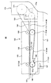
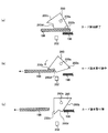
図1は、この発明の実施の形態にかかる退場カード発行ユニットを示す斜視図、図2は、退場カード発行ユニットのカード搬送装置の要部を模式的に示す断面図、図3は、カードの搬出・搬送過程(a)とカードの搬送終了状態(b)を示す説明図、図4は、カードの排出終了時(a)とカード抜き取り途中(b)とカード抜き取り後(c)におけるシャッタの動作を示す側面図、図5は、反りのあるカードがガイドレールによって案内搬送される様子を示す断面図、図6は、カードがガイドレールによって案内搬送される様子を示す平面図である。なお、以下の説明において、すでに説明した部材と同一もしくは相当する部材には、同一の符号を付して重複説明を省略または簡略化する。
【0027】
退場カード発行ユニット88は、図1および図2に示すように、カード198を前面扉2の退場カード取出口100へ搬送するカード搬送装置180と、カード貯留部171に予め貯留しているカード198をこのカード搬送装置180に搬出するカード搬出装置170とから構成されている。両装置170,180は、基台181上に設けられている。この基台181は、ローラ182aを有するスライド部182を備えており、本体ケース1に設けられたスライド式レール機構(図示せず)に搭載されている。
【0028】
カード搬出装置170は、カード198をカード搬送装置180に搬出するために、図示しないプーリおよび搬送ベルトからなる搬出機構を備えており、モータ172を駆動源として動作するようになっている。カード搬送装置180の搬送駆動源は、このモータ172の駆動力を用いている。すなわち、モータ172の駆動力は、プーリ173,174,174aおよびベルト184によって、カード搬送装置180の側板部183外部に設けられたプーリ188に伝達されるようになっている。
【0029】
側板部183の内部であってプーリ188のシャフトには、プーリ190が設けられている。このプーリ190は、プーリ191,192,193とともにベルト194を駆動するようになっている。プーリ191等は、シャフト191a等によって回転自在に軸支されている。ローラ195は、ばね手段(図示せず)によってベルト194側に付勢されており、ベルト194によって搬送されるカード198を所定圧力で押圧するように形成されている。
【0030】
側板部183の内壁面に設けた1対のガイドレール196,196は、図2、図5および図6に示すように、ベルト194によって搬送されるカード198の両端部を支持し、カード198をカード取出開口部185に円滑に案内するとともに、カード取出開口部185近傍においてガイドレール196,196を次第に幅広にして近接させ、その案内溝どうしを連通部196aで連通させることによって、反りの生じたカード198を徐々に整形して反りのない状態でカード取出開口部185から送出できるようにし、詰まりを防止するようにしたものである。
【0031】
カード取出開口部185に設けた除電ブラシ186は、搬送され帯電したカード198の静電気を除去するとともに、搬送直後のカード198に所定の摩擦抵抗を付与することによってカード198が慣性力でカード取出開口部185から飛び出すのを防止するためのものである。なお、除電ブラシ186の配線は、基台181とアース部187により接続されている。
【0032】
シャッタ200は、図3および図4に示すように、カード取出開口部185においてカード198の逆入れを防止し、カード198の抜き取り検知を確実なものとするために設けたものである。すなわち、シャッタ200は、ベルト194の搬送方向終端部とカード取出開口部185との間に、カード198の抜き取りを検知するセンサ202とともに設けられ、このセンサ202の上部に対向配置されている。ガイドレール196に案内されたカード198は、このシャッタ200とセンサ202との間を通過するようになっている。
【0033】
シャッタ200は、板状部材によって形成され、軸200aによって回転自在に設けられている。シャッタ200は、通常はカード198の通過経路を塞ぐように閉じている(初期状態)。このとき、シャッタ200の傾斜部200bは、ガイドレール196に当接しており、シャッタ200が同図の反時計回り方向にそれ以上回転しないようになっている。
【0034】
つぎに、シャッタ200の動作について説明する。図4(a)に示すように、ベルト194による搬送が終わると、シャッタ200の傾斜部200bがカード198によって押され、シャッタ200は、傾斜部200bがカード198と平行になるまで回転(同図では、時計回り)する。
【0035】
そして、図4(b)に示すように、センサ202によりカード198末端部の通過が検知され、抜き取り検知がなされる。すなわち、カード198の搬送終了検知と抜き取り検知の両方を1つのセンサ202で行うことができる。このとき、傾斜部200bは、カード198と当接していないので、シャッタ200は自重により回転し(同図では、反時計回り)、上記初期状態に復帰しようとする。抜き取り検知後にカード198を逆入れしようとしても、カード198の後端部が突部200cおよび段部200dによって進入を規制される。
【0036】
続いて、図4(c)に示すように、カード198がカード取出開口部185から抜き取られると、シャッタ200がさらに回転(同図では、反時計回り)して完全に閉じ、上記初期状態に戻る。このとき、シャッタ200の傾斜部200bは、ガイドレール196に当接しており、シャッタ200が同図の反時計回り方向にそれ以上回転しないようになっているので、カード198を逆入れしようとしてもシャッタ200は開かず、かかる行為を有効に防止する。
【0037】
なお、カード搬送装置180をカードリーダ300に交換する場合には、モータ172の駆動力をプーリ188に伝達するベルト184を外して、プーリ173,174,174aにカード搬出機構専用のベルト(図示せず)を装着すればよい。
【0038】
以上のように、この実施の形態にかかるリストバンド自動精算機によれば、カードリーダ300と互換性があり、カード搬出装置170の駆動源を共用できるカード搬送装置180を有した退場カード発行ユニット88を備えて構成したので、カード搬出装置170から搬出されたカード198を簡易な構成によって確実に搬送・搬出できるとともに、メンテナンス性を犠牲にすることなく、顧客側の運用変更に柔軟かつ低コストで対応できる。
【0039】
また、シャッタ200およびセンサ202を設けたことで、従来のようなソレノイド304による機構や複数のセンサ302,306が不要となり、きわめて簡易な構成にてカード198の搬送・抜き取り状態を確実に検知できるとともに、カードの逆入れを有効に防止できる。
【0040】
また、ガイドレール196を設けたことにより、反りの生じたカード198を徐々に整形して反りのない状態でカード取出開口部185から送出でき、カード198の詰まりを防止できる。
【0041】
また、カード取出開口部185に除電ブラシ186を設けたことにより、搬送され帯電したカード198の静電気を除去できるとともに、搬送直後のカード198が慣性力でカード取出開口部185から飛び出すのを防止できる。
【0042】
【発明の効果】
以上説明したように、この発明にかかるリストバンド自動精算機(請求項1)によれば、精算後に退場カードを発行する退場カード発行ユニットを備えたリストバンド自動精算機において、前記退場カード発行ユニットは、前記退場カードを退場カード取出口へ搬送手段によって搬送するカード搬送装置と、予め貯留している前記退場カードを前記カード搬送装置に搬出するカード搬出装置とを備え、前記カード搬送装置は、退場カードを案内する案内溝を有したガイドレールを搬送方向と平行に一対備え、前記一対のガイドレールは、カード取出開口部に近づくにしたがって互いに近接するとともに、当該カード取出開口部直前において互いの前記案内溝どうしが連通するように形成したので、反りの生じた退場カードを徐々に整形して反りのない状態でカード取出開口部から送出でき、カード詰まり等を防止できる。
【0043】
また、この発明にかかるリストバンド自動精算機(請求項2)によれば、カード搬送装置は、退場カード取出口からの退場カードの逆入れを防止するために、当該退場カード取出口と搬送手段終端部との間にシャッタを備え、前記シャッタは、前記搬送手段を経た前記退場カードの進入時の当接により姿勢を変化させて当該退場カードの通路を開けるとともに、当該退場カードの通過後の当接解除により自重で姿勢を変化させて当該退場カードの通路を閉じるように形成したので、きわめて簡易な構成にて退場カード取出口からの退場カードの逆入れを防止でき、カード詰まり等を防止できる。
【0044】
また、この発明にかかるリストバンド自動精算機(請求項3)によれば、シャッタは、搬送手段を経た退場カードの通過途中の当接により姿勢を変化させて当該退場カードの通路を閉じるように形成したので、退場カードの通過途中においても、退場カードの逆入れを防止でき、カード詰まり等を防止できる。
【0045】
また、この発明にかかるリストバンド自動精算機(請求項4)によれば、退場カードの通過を検知するセンサ手段を、搬送手段終端部とシャッタとの間に配設したので、一つのセンサ手段により、退場カードの搬送終了と抜き取りとを確実に検知できる。
【0047】
また、この発明にかかるリストバンド自動精算機(請求項5)によれば、カード取出開口部には、搬出された退場カードに当接し当該退場カードの静電気を除去する除電ブラシを備えたので、帯電したカードの静電気を除去できるとともに、搬送直後のカードが慣性力でカード取出開口部から飛び出すのを防止できる。
【図面の簡単な説明】
【図1】この発明の実施の形態にかかる退場カード発行ユニットを示す斜視図である。
【図2】退場カード発行ユニットのカード搬送装置の要部を模式的に示す断面図である。
【図3】カードの搬出・搬送過程(a)とカードの搬送終了状態(b)を示す説明図である。
【図4】カードの排出終了時(a)とカード抜き取り途中(b)とカード抜き取り後(c)におけるシャッタの動作を示す側面図である。
【図5】反りのあるカードがガイドレールによって案内搬送される様子を示す断面図である。
【図6】カードがガイドレールによって案内搬送される様子を示す平面図である。
【図7】リストバンド自動精算機を示す背面斜視図である。
【図8】リストバンド自動精算機を示す正面斜視図である。
【図9】リストバンド自動精算機を示す正面図である。
【図10】リストバンドを示す平面図である。
【図11】従来の退場カード発行ユニットの要部を模式的に示す断面図である。
【符号の説明】
88 退場カード発行ユニット
170 カード搬出装置
171 カード貯留部
172 モータ
173、174、174a、188 プーリ
180 カード搬送装置
181 基台
182 スライド部
182a ローラ
183 側板部
184、194 ベルト
185 カード取出開口部
186 除電ブラシ
187 アース部
190、191、192、193 プーリ
191a シャフト
195 ローラ
196 ガイドレール
196a 連通部
198 カード
200 シャッタ
200a 軸
200b 傾斜部
200c 突部
202 センサ[0001]
BACKGROUND OF THE INVENTION
The present invention relates to a wristband automatic settlement machine.
[0002]
[Prior art]
For example, in a 24-hour business facility such as a so-called health land, it is required that maintenance of the wristband automatic settlement machine can be performed without hindering the use of the facility user even during business. Therefore, the applicant of the present application has proposed a wristband automatic settlement machine that can easily maintain various components from both the front door side and the rear door side in Japanese Patent Application No. 2000-230309. This automatic wristband checker includes an exit card issuing unit that issues an exit card when a user leaves the facility.
[0003]
The exit card issuing unit writes a predetermined data such as an exit time on the exit card and transports it to the exit card exit of the front door and an exit card stored in advance. Card unloading device for unloading. Hereinafter, a conventional wristband automatic settlement machine equipped with such an exit card issuing unit will be described.
[0004]
First, the overall configuration of the wristband automatic settlement machine will be described. 7 is a rear perspective view showing the wristband automatic settlement machine, FIG. 8 is a front perspective view showing the wristband automatic settlement machine, FIG. 9 is a front view showing the wristband automatic settlement machine, and FIG. It is a top view which shows a wristband. A main body case 1 that accommodates each component device includes a
[0005]
The wristband 5 includes a tag unit 5a, a band unit 5b, and a key 5c. The tag unit 5a incorporates an ID tag memory including an EEPROM that does not require a battery. That is, the facility user's personal information (for example, a locker number or the like) is written in the tag portion 5a. The
[0006]
The wristband temporary holding unit 40 provided on the inner surface of the
[0007]
The coin hopper 60 stores coins for change and pays out coins when necessary. The
[0008]
The
[0009]
The exit
[0010]
The
[0011]
Next, the exit
[0012]
In the
[0013]
The end of the conveyance path of the
[0014]
[Problems to be solved by the invention]
However, since the exit
[0015]
When such a data writing function is not required, the card carry-out
[0016]
Further, the
[0017]
The present invention has been made in view of the above, and the card unloaded from the card unloading device can be reliably conveyed and unloaded with a simple configuration, and can easily maintain compatibility with the card reader. It is an object of the present invention to provide a wristband automatic settlement machine equipped with an exit card issuing unit that can respond flexibly and inexpensively to operational changes.
[0018]
Another object of the present invention is to provide a wristband automatic checkout machine equipped with an exit card issuing unit that can reliably detect the card conveyance / removal state with a simple configuration and can effectively prevent reverse insertion of the card. And
[0019]
[Means for Solving the Problems]
In order to achieve the above-mentioned object, the automatic wristband settlement machine according to claim 1 of the present invention is a wristband automatic settlement machine comprising an exit card issuance unit that issues an exit card after settlement. Comprises a card transport device that transports the exit card to the exit card exit by transport means, and a card transport device that transports the exit card stored in advance to the card transport device, the card transport device comprising: A pair of guide rails having guide grooves for guiding exit cards are provided in parallel with the transport direction, and the pair of guide rails come closer to each other as they approach the card extraction opening, and each other immediately before the card extraction opening. The guide grooves are formed so as to communicate with each other. As a result, the exit card with warping can be gradually shaped and sent out from the card takeout opening without warping, and card jamming can be prevented.
[0020]
Further, in the wristband automatic settlement machine according to
[0021]
In the wristband automatic settlement machine according to
[0022]
According to a fourth aspect of the present invention, there is provided a wristband automatic settlement machine in which sensor means for detecting passage of an exit card is disposed between a conveying means terminal portion and a shutter. Thereby, the completion | finish and conveyance of a leaving card can be reliably detected with one sensor means.
[0024]
According to a fifth aspect of the present invention, there is provided a wristband automatic settlement machine, wherein the card takeout opening is provided with a static elimination brush that abuts the removed exit card and removes static electricity from the exit card. As a result, the static electricity of the charged card can be removed, and the card immediately after transport can be prevented from jumping out of the card extraction opening due to inertial force.
[0025]
DETAILED DESCRIPTION OF THE INVENTION
DESCRIPTION OF THE PREFERRED EMBODIMENTS Embodiments of a wristband automatic settlement machine according to the present invention will be described in detail below with reference to the drawings. Note that the present invention is not limited to the embodiments.
[0026]
FIG. 1 is a perspective view showing an exit card issuing unit according to an embodiment of the present invention, FIG. 2 is a cross-sectional view schematically showing a main part of a card transport device of the exit card issuing unit, and FIG. FIG. 4 is an explanatory diagram showing the unloading / transporting process (a) and the card transporting end state (b), and FIG. 4 shows the shutter at the end of card ejection (a), in the middle of card removal (b), and after card removal (c). FIG. 5 is a cross-sectional view showing how a warped card is guided and conveyed by the guide rail, and FIG. 6 is a plan view showing how the card is guided and conveyed by the guide rail. In the following description, members that are the same as or correspond to those already described are denoted by the same reference numerals, and redundant description is omitted or simplified.
[0027]
As shown in FIGS. 1 and 2, the exit
[0028]
The card carry-out
[0029]
A pulley 190 is provided inside the
[0030]
A pair of
[0031]
The
[0032]
As shown in FIGS. 3 and 4, the
[0033]
The
[0034]
Next, the operation of the
[0035]
And as shown in FIG.4 (b), passage of the card |
[0036]
Subsequently, as shown in FIG. 4 (c), when the
[0037]
When the
[0038]
As described above, according to the wristband automatic settlement machine according to this embodiment, the exit card issuing unit having the
[0039]
Further, since the
[0040]
Further, by providing the
[0041]
Further, by providing the
[0042]
【The invention's effect】
As described above, according to the wristband automatic settlement machine according to the present invention (claim 1), in the wristband automatic settlement machine including the exit card issuing unit that issues the exit card after settlement, the exit card issuing unit Comprises a card transport device that transports the exit card to the exit card exit by transport means, and a card transport device that transports the exit card stored in advance to the card transport device, the card transport device comprising: A pair of guide rails having guide grooves for guiding exit cards are provided in parallel with the transport direction, and the pair of guide rails come closer to each other as they approach the card extraction opening, and each other immediately before the card extraction opening. Since the guide grooves are formed so as to communicate with each other, the warped exit card is gradually shaped and bent. In the absence of possible sent from the card dispensing opening, thereby preventing the card jam.
[0043]
In addition, according to the wristband automatic settlement machine according to the present invention (claim 2), the card transport device has the exit card take-out port and the transport means for preventing reverse placement of the exit card from the exit card exit. A shutter is provided between the terminal and the terminal, and the shutter changes its posture by contact when the exit card enters through the transport means to open the exit card passage, and after the exit card has passed. By changing the posture with its own weight by releasing the contact, the exit card passage is closed, so the exit card can be prevented from being reversely inserted from the exit card exit with a very simple configuration, preventing card jams, etc. it can.
[0044]
Further, according to the wristband automatic settlement machine according to the present invention (claim 3), the shutter is changed in posture by abutment in the middle of passing of the exiting card that has passed through the conveying means so as to close the passage of the exiting card. Since the exit card is formed, the exit card can be prevented from being reversely inserted even while the exit card is passing, and card jamming or the like can be prevented.
[0045]
According to the wristband automatic settlement machine of the present invention (Claim 4), the sensor means for detecting passage of the exit card is disposed between the conveying means terminal and the shutter, so that one sensor means is provided. Thus, it is possible to reliably detect the completion and removal of the exit card.
[0047]
Further, according to the wristband automatic settlement machine according to the present invention (Claim 5 ), the card removal opening portion is provided with a static elimination brush that comes into contact with the removed exit card and removes static electricity from the exit card. In addition to removing static electricity from the charged card, it is possible to prevent the card immediately after transport from jumping out of the card extraction opening due to inertia.
[Brief description of the drawings]
FIG. 1 is a perspective view showing an exit card issuing unit according to an embodiment of the present invention.
FIG. 2 is a cross-sectional view schematically showing a main part of a card transport device of an exit card issuing unit.
FIG. 3 is an explanatory diagram showing a card unloading / carrying process (a) and a card carrying end state (b).
FIG. 4 is a side view showing the operation of the shutter at the end of card ejection (a), during card removal (b), and after card removal (c).
FIG. 5 is a cross-sectional view showing how a warped card is guided and conveyed by a guide rail.
FIG. 6 is a plan view showing a state where a card is guided and conveyed by a guide rail.
FIG. 7 is a rear perspective view showing a wristband automatic settlement machine.
FIG. 8 is a front perspective view showing a wristband automatic settlement machine.
FIG. 9 is a front view showing a wristband automatic settlement machine.
FIG. 10 is a plan view showing a wristband.
FIG. 11 is a cross-sectional view schematically showing a main part of a conventional exit card issuing unit.
[Explanation of symbols]
88 Exit
Claims (5)
前記退場カード発行ユニットは、前記退場カードを退場カード取出口へ搬送手段によって搬送するカード搬送装置と、
予め貯留している前記退場カードを前記カード搬送装置に搬出するカード搬出装置と、
を備え、
前記カード搬送装置は、退場カードを案内する案内溝を有したガイドレールを搬送方向と平行に一対備え、
前記一対のガイドレールは、カード取出開口部に近づくにしたがって互いに近接するとともに、当該カード取出開口部直前において互いの前記案内溝どうしが連通するように形成したことを特徴とするリストバンド自動精算機。In a wristband automatic checkout machine equipped with an exit card issuing unit that issues exit cards after checkout,
The exit card issuing unit includes a card transport device that transports the exit card to the exit card exit by transport means;
A card unloading device for unloading the exit card stored in advance to the card conveying device;
With
The card transport device comprises a pair of guide rails having guide grooves for guiding exit cards in parallel with the transport direction,
The pair of guide rails are formed so that the guide grooves are close to each other as they approach the card extraction opening, and the guide grooves communicate with each other immediately before the card extraction opening. .
前記シャッタは、前記搬送手段を経た前記退場カードの進入時の当接により姿勢を変化させて当該退場カードの通路を開けるとともに、当該退場カードの通過後の当接解除により自重で姿勢を変化させて当該退場カードの通路を閉じるように形成したことを特徴とする請求項1に記載のリストバンド自動精算機。The card transport device includes a shutter between the exit card exit and the transport means terminal in order to prevent reverse exit of the exit card from the exit card exit,
The shutter changes its posture by contact when the exit card enters through the transport means to open the passage of the exit card, and changes its posture by its own weight by releasing contact after the exit card passes. The wristband automatic settlement machine according to claim 1, wherein the exit card is formed so as to close a passage of the exit card.
Priority Applications (1)
| Application Number | Priority Date | Filing Date | Title |
|---|---|---|---|
| JP2000333963A JP4006940B2 (en) | 2000-10-31 | 2000-10-31 | Wristband automatic payment machine |
Applications Claiming Priority (1)
| Application Number | Priority Date | Filing Date | Title |
|---|---|---|---|
| JP2000333963A JP4006940B2 (en) | 2000-10-31 | 2000-10-31 | Wristband automatic payment machine |
Publications (2)
| Publication Number | Publication Date |
|---|---|
| JP2002140739A JP2002140739A (en) | 2002-05-17 |
| JP4006940B2 true JP4006940B2 (en) | 2007-11-14 |
Family
ID=18809960
Family Applications (1)
| Application Number | Title | Priority Date | Filing Date |
|---|---|---|---|
| JP2000333963A Expired - Fee Related JP4006940B2 (en) | 2000-10-31 | 2000-10-31 | Wristband automatic payment machine |
Country Status (1)
| Country | Link |
|---|---|
| JP (1) | JP4006940B2 (en) |
-
2000
- 2000-10-31 JP JP2000333963A patent/JP4006940B2/en not_active Expired - Fee Related
Also Published As
| Publication number | Publication date |
|---|---|
| JP2002140739A (en) | 2002-05-17 |
Similar Documents
| Publication | Publication Date | Title |
|---|---|---|
| US4007356A (en) | Card retrieval means | |
| JP2000189658A (en) | Game medium dispensing device, and prepaid card control system using this game medium dispensing device | |
| JP4523497B2 (en) | Banknote handling equipment | |
| JP4006940B2 (en) | Wristband automatic payment machine | |
| JP4017052B2 (en) | Vending machines that can use IC cards | |
| EP0456814B1 (en) | Sheet handling apparatus | |
| JP4701121B2 (en) | Cassette-type medium storage container, hopper, and medium issuing device | |
| JP3605109B2 (en) | Card processing equipment | |
| JP2006189957A (en) | Card processing apparatus | |
| JP4186033B2 (en) | Magnetic card and IC card processing method in handling device for plural types of memory cards | |
| JP2002024875A (en) | Wristband automatic settlement machine | |
| JPS60123991A (en) | Coin processor | |
| JP5448401B2 (en) | Bill processing device and game medium lending device | |
| JP4748469B2 (en) | Recording medium processing apparatus and gaming apparatus | |
| JPS61121189A (en) | Automatic transactor | |
| JP4530202B2 (en) | Non-contact automatic ticket gate used in ticket gate processing system | |
| JP2002024874A (en) | Wristband automatic settlement machine | |
| JP2002024870A (en) | Wristband automatic settlement machine | |
| JP2002024872A (en) | Wristband automatic settlement machine | |
| JP3145613B2 (en) | Card handling device | |
| JPS6142313B2 (en) | ||
| JP3330258B2 (en) | Card feeding device | |
| JP2915755B2 (en) | Magnetic card reader | |
| JPS5849914B2 (en) | Butupin Ruinoshiharai Aruiha Azukeireki | |
| JP2002024877A (en) | Wristband automatic settlement machine |
Legal Events
| Date | Code | Title | Description |
|---|---|---|---|
| A621 | Written request for application examination |
Free format text: JAPANESE INTERMEDIATE CODE: A621 Effective date: 20050914 |
|
| A977 | Report on retrieval |
Free format text: JAPANESE INTERMEDIATE CODE: A971007 Effective date: 20070523 |
|
| A131 | Notification of reasons for refusal |
Free format text: JAPANESE INTERMEDIATE CODE: A131 Effective date: 20070529 |
|
| A521 | Written amendment |
Free format text: JAPANESE INTERMEDIATE CODE: A523 Effective date: 20070712 |
|
| TRDD | Decision of grant or rejection written | ||
| A01 | Written decision to grant a patent or to grant a registration (utility model) |
Free format text: JAPANESE INTERMEDIATE CODE: A01 Effective date: 20070807 |
|
| A61 | First payment of annual fees (during grant procedure) |
Free format text: JAPANESE INTERMEDIATE CODE: A61 Effective date: 20070820 |
|
| FPAY | Renewal fee payment (event date is renewal date of database) |
Free format text: PAYMENT UNTIL: 20100907 Year of fee payment: 3 |
|
| R150 | Certificate of patent or registration of utility model |
Free format text: JAPANESE INTERMEDIATE CODE: R150 |
|
| FPAY | Renewal fee payment (event date is renewal date of database) |
Free format text: PAYMENT UNTIL: 20110907 Year of fee payment: 4 |
|
| FPAY | Renewal fee payment (event date is renewal date of database) |
Free format text: PAYMENT UNTIL: 20110907 Year of fee payment: 4 |
|
| FPAY | Renewal fee payment (event date is renewal date of database) |
Free format text: PAYMENT UNTIL: 20120907 Year of fee payment: 5 |
|
| FPAY | Renewal fee payment (event date is renewal date of database) |
Free format text: PAYMENT UNTIL: 20120907 Year of fee payment: 5 |
|
| S531 | Written request for registration of change of domicile |
Free format text: JAPANESE INTERMEDIATE CODE: R313531 |
|
| FPAY | Renewal fee payment (event date is renewal date of database) |
Free format text: PAYMENT UNTIL: 20120907 Year of fee payment: 5 |
|
| R350 | Written notification of registration of transfer |
Free format text: JAPANESE INTERMEDIATE CODE: R350 |
|
| FPAY | Renewal fee payment (event date is renewal date of database) |
Free format text: PAYMENT UNTIL: 20120907 Year of fee payment: 5 |
|
| FPAY | Renewal fee payment (event date is renewal date of database) |
Free format text: PAYMENT UNTIL: 20130907 Year of fee payment: 6 |
|
| FPAY | Renewal fee payment (event date is renewal date of database) |
Free format text: PAYMENT UNTIL: 20130907 Year of fee payment: 6 |
|
| S111 | Request for change of ownership or part of ownership |
Free format text: JAPANESE INTERMEDIATE CODE: R313111 |
|
| FPAY | Renewal fee payment (event date is renewal date of database) |
Free format text: PAYMENT UNTIL: 20130907 Year of fee payment: 6 |
|
| R350 | Written notification of registration of transfer |
Free format text: JAPANESE INTERMEDIATE CODE: R350 |
|
| R250 | Receipt of annual fees |
Free format text: JAPANESE INTERMEDIATE CODE: R250 |
|
| R250 | Receipt of annual fees |
Free format text: JAPANESE INTERMEDIATE CODE: R250 |
|
| R250 | Receipt of annual fees |
Free format text: JAPANESE INTERMEDIATE CODE: R250 |
|
| LAPS | Cancellation because of no payment of annual fees |