JP4006636B2 - Composite speaker - Google Patents
Composite speaker Download PDFInfo
- Publication number
- JP4006636B2 JP4006636B2 JP2002309761A JP2002309761A JP4006636B2 JP 4006636 B2 JP4006636 B2 JP 4006636B2 JP 2002309761 A JP2002309761 A JP 2002309761A JP 2002309761 A JP2002309761 A JP 2002309761A JP 4006636 B2 JP4006636 B2 JP 4006636B2
- Authority
- JP
- Japan
- Prior art keywords
- speaker
- piezoelectric
- protector
- composite
- diaphragm
- Prior art date
- Legal status (The legal status is an assumption and is not a legal conclusion. Google has not performed a legal analysis and makes no representation as to the accuracy of the status listed.)
- Expired - Fee Related
Links
Images


Description
【0001】
【発明の属する技術分野】
本発明は、ダイナミックスピーカと圧電スピーカとを組み合わせてなる複合型スピーカに係り、特に、広い周波数帯域に渡って良好な再生特性を確保できると共に、より一層の省スペース化、並びに製造コストおよび製品コストの低下を図ることができる複合型スピーカに関する。
【0002】
【従来の技術】
【特許文献1】
特開2000−78691号公報
【特許文献2】
特許第2010415号明細書
【特許文献3】
特開平11−331976号公報
従来のダイナミックスピーカの一例として、コーンスピーカの構造を図4および図5に示す。図4(a)は本従来例のコーンスピーカを背面から見た外観図、図4(b)はそれを正面から見た外観図、図5は図4(a)のB−B’線に沿った断面図である。
【0003】
スピーカ本体101の基本的構造は、駆動力を発生するためのボイスコイル115、磁気回路(マグネット114)およびヨーク103と、ボイスコイル115の先端に連結されたコーン(円錐)状の振動板113と、これら各部品を連結するフレーム112とを備えたものである。フレーム112に取り付けられた端子台106には、金属製のスピーカプラス端子107とスピーカマイナス端子108が組み込まれている。これらの端子107と108は、それぞれ、ボイスコイルリード線116によってボイスコイル115と電気的に接続されている。
【0004】
フレーム112の前端面には、振動板113を保護するために、円板状のスピーカプロテクタ102が取り付けられている。このスピーカプロテクタ102は、薄い金属板(例えば、SUS)で構成されており、スピーカ本体101の内部で振動板113が生成する音波を外部に放出するために、複数の前面音孔105が設けられている。フレーム112の背面には、スピーカ本体101の内部で振動板113が生成する音波を外部に放出するために、複数の背面音孔104が設けられている。
【0005】
【発明が解決しようとする課題】
上述した構造を持つダイナミックスピーカでは、音圧の周波数特性が、振動板113の速度特性に密接に関係していて、振動板113の口径や質量に依存して変化することから、1つの振動板113で所望周波数帯域の全体にわたって良好な音圧特性を確保することは困難である。このため、従来より、口径の異なる複数のスピーカ・ユニットを組み合わせることにより、所望の周波数帯域の全体にわたって良好な周波数特性を確保するようにした「マルチウェイ・スピーカ」が提案されている。
【0006】
しかしながら、携帯機器等のスペースの限られた機器に搭載する場合には、複数のスピーカ・ユニットを搭載するスペースを確保することが困難である。そこで、ダイナミックスピーカと圧電型スピーカとを組み合わせることにより、省スペース化を図ると共に、広い周波数帯域にわたって良好な周波数特性を確保するものが提案されている。
【0007】
例えば、特許文献1(特開2000−78691号公報)では、超高域までの良好な音響特性を持ち、放熱条件の悪い場所でも耐入力性を持たせることを目的として、コーン振動板を備えたダイナミックスピーカと、そのダイナミックスピーカのセンターキャップ部に配置された圧電スピーカを備えた構造の複合型スピーカが開示されている。圧電スピーカは、その内部に振動体を有している。したがって、ダイナミックスピーカは、それ自身のコーン振動板を持ち、圧電スピーカもそれ自身の振動体を持っている。
【0008】
特許文献2(特許第2010415号明細書)には、ダイナミックスピーカの可動コイルに過大な負荷をかけることなしに、コーン振動板を反射面として用いて、圧電スピーカのセラミック円板およびそれぞれの円錐形ダイヤフラムにより放射された後方からの音波を十分に利用することを可能にする、支持体により保持された圧電スピーカを備えた構造の複合型スピーカが開示されている。
【0009】
特許文献3(特開平11−331976号公報)には、圧電スピーカの音色を改善する観点から、バッフル(振動板の前面および背面から放射される音が混じり合わないようにお互いを遮断する障壁)にダイナミックスピーカを取り付け、該ダイナミックスピーカの前方領域に音響振動板を配設し、その音響振動板に圧電振動体を取り付けた構造の複合型スピーカが開示されている。
【0010】
しかしながら、これら特許文献1〜3に開示された従来の複合型スピーカは、いずれも、異なる口径の振動板(振動体)を含む複合振動板を持っているため、スピーカ単体の大きさが増大すると共に、スピーカの厚みも増えてしまうという問題がある。また、構造が複雑で部品点数も増えることから、製造コストおよび製品コストが上昇するという難点もある。
【0011】
本発明は、上記従来の事情に鑑みてなされたものであって、その目的とするところは、広い周波数帯域にわたって良好な音響特性を確保できると共に、より一層の省スペース化を図ることができる複合型スピーカを提供することにある。
【0012】
本発明の他の目的は、より簡単な構造によってダイナミックスピーカと圧電スピーカとを組み合わせた複合型スピーカを提供することである。
【0013】
本発明のさらに他の目的は、部品点数が少ないと共に、製造が容易で低コスト化を図り得る複合型スピーカを提供することである。
【0014】
ここに明記しない本発明のさらに他の目的は、以下の説明および添付図面から明らかになる。
【0015】
【課題を解決するための手段】
(1) 本発明の第1の観点による複合型スピーカは、
ダイナミックスピーカと圧電スピーカとを組み合わせてなる複合型スピーカであって、
前記ダイナミックスピーカは、振動板の前方に設けられた当該振動板保護用のプロテクタを備えており、
前記圧電スピーカは、前記プロテクタの前面または背面に取り付けられた圧電体を有していると共に、当該圧電体の伸縮運動によって当該プロテクタが前記圧電スピーカの振動板として動作するように構成されており、
前記ダイナミックスピーカへの信号の印加と前記圧電スピーカへの信号の印加は、共通の端子を介して行われることを特徴とするものである。
【0016】
(2) 本発明の第1の観点による複合型スピーカでは、前記ダイナミックスピーカの振動板の前方に設けられた当該振動板保護用のプロテクタの前面または背面に圧電体を取り付け、当該圧電体の伸縮運動によって当該プロテクタが前記圧電スピーカの振動板として動作するように構成されている。換言すれば、前記ダイナミックスピーカが備えている前記プロテクタと、その前面または背面に取り付けられた前記圧電体により前記圧電スピーカを構成し、前記プロテクタを前記圧電スピーカの振動板として機能させるものである。このため、前記圧電スピーカを高音域音声信号用として使用することにより、高域周波数特性の改善が期待でき、よって広い周波数帯域にわたって良好な音響特性を確保することができる。
【0017】
また、当該複合型スピーカの厚みは、前記圧電体を前記プロテクタの背面に取り付けた場合には、前記ダイナミックスピーカと同じであり、前記圧電体を前記プロテクタの前面に取り付けた場合でも、前記圧電体の厚みに相当する厚みが加わるだけであるので、従来の複合型スピーカに比べてより一層の薄型化および省スペース化を図ることができる。
【0018】
さらに、前記プロテクタを前記圧電スピーカの振動板として使用すると共に、前記ダイナミックスピーカへの信号の印加と前記圧電スピーカへの信号の印加を共通の端子を介して行うので、前記ダイナミックスピーカと前記圧電スピーカの部品の共通化により、製品コストを抑えることができる。また、従来の複合型スピーカに比べてより簡単な構造であるので、部品点数を格段に削減することができ、よって製品の低コスト化を図ることができる。そして、振動板保護用のプロテクタを有する従来のダイナミックスピーカの構成に対して前記圧電体を取り付けるだけで構成できるので、具体的な製造工程についても、圧電体の貼り付け工程およびリード線の接続工程を追加するだけでよく、その結果、製造が容易で製造コストを抑えることができる。
【0019】
(3) 本発明の第1の観点による複合型スピーカでは、前記圧電体を前記プロテクタの中心部に取り付けるのが望ましい。こうすることにより、前記ダイナミックスピーカと前記圧電スピーカが同軸に配置されることとなり、それらのスピーカの指向特性の中心軸が同軸に揃えられるので、音響再生による音像の中心位置や音像の大きさが高音域に至るまであまり変化することがなく、正確な音像定位が得られることとなり、高音域までの音響特性が良好となる。
【0020】
(4) 本発明の第2の観点による複合型スピーカは、
ダイナミックスピーカと圧電スピーカとを組み合わせてなる複合型スピーカであって、
前記ダイナミックスピーカは、振動板の前方に設けられた当該振動板保護用のプロテクタを備えており、
前記圧電スピーカは、前記プロテクタの前面および背面にそれぞれ取り付けられた第1および第2の圧電体を有していると共に、当該第1および第2の圧電体の伸縮運動によって当該プロテクタが前記圧電スピーカのバイモルフ振動体として動作するように構成されており、
前記ダイナミックスピーカへの信号の印加と前記圧電スピーカへの信号の印加は、共通の端子を介して行われることを特徴とするものである。
【0021】
(5) 本発明の第2の観点による複合型スピーカでは、前記プロテクタの前面および背面に前記第1および第2の圧電体を取り付け、当該第1および第2の圧電体の伸縮運動によって当該プロテクタが前記圧電スピーカのバイモルフ振動体として動作するように構成されているので、前記プロテクタとその前面および背面に取り付けられた前記第1および第2の圧電体とによりバイモルフ型の圧電スピーカが構成される。よって、本発明の第1の観点による複合型スピーカと同様の効果、すなわち、広い周波数帯域にわたる良好な音響特性の確保、薄型化および省スペース化、製品コストおよび製造コストの抑制、並びに、部品点数の削減による製品の低コスト化を実現できる。また、本発明の第1の観点による複合型スピーカよりも、圧電スピーカの音圧を増大させることができる、という利点もある。
【0022】
(6) 本発明の第2の観点による複合型スピーカでは、好ましくは、前記第1および第2の圧電体がそれらの分極方向が互いに逆になるように取り付けられる場合には、前記第1および第2の圧電体に同極性の信号を印加するようにする。前記第1および第2の圧電体がそれらの分極方向が互いに同一になるように取り付けられる場合には、前記第1および第2の圧電体に逆極性の信号を印加するようにする。こうすることにより、バイモルフ型の圧電スピーカが得られるからである。
【0023】
また、本発明の第2の観点の複合型スピーカでは、前記圧電体を金属製プロテクタの中心部に取り付けるのが望ましい。こうすることにより、前記ダイナミックスピーカと前記圧電スピーカが同軸に配置されることとなり、それらのスピーカの指向特性の中心軸が同軸に揃えられるので、音響再生による音像の中心位置や音像の大きさが高音域に至るまであまり変化することがなく、正確な音像定位が得られることとなり、高音域までの音響特性が良好となる。
【0024】
【発明の実施の形態】
以下、本発明の好適な実施の形態について、〔第1実施形態〕、〔第2実施形態〕の順に添付図面を参照して説明する。
【0025】
〔第1実施形態〕
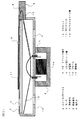
まず、本発明の第1実施形態に係る複合型スピーカを図1および図2を参照して説明する。図1(a)は本実施形態の複合型スピーカを背面から見た外観図、図1(b)は正面から見た外観図、図2は本実施形態の複合型スピーカについて図1(a)のA−A’線に沿った断面図である。
【0026】
本実施形態の複合型スピーカにおいて、スピーカ本体1の基本的構造はダイナミックスピーカとしてのものであり、駆動力を発生するためのボイスコイル15と磁気回路(マグネット14)とヨーク3、ボイスコイル15の先端に連結された振動板13、そしてこれら各部品を連結するフレーム12とを備えている。フレーム12は、前端面を開口した略円筒形である。ヨーク3は、フレーム12の背面に固着されており、ヨーク3の内部にマグネット14とボイスコイル15が配置されている。ボイスコイル15の前端は、振動板13に接続されている。ボイスコイル15は前後に変位可能であって、その変位によって振動板13が振動せしめられて音波が生成される。
【0027】
フレーム12の一端に固着された端子台6には、金属製のスピーカプラス端子7とスピーカマイナス端子8が組み込まれており、これら端子はそれぞれボイスコイルリード線16によってボイスコイル15と電気的に接続されている。
【0028】
フレーム12の前端面の開口には、振動板13を保護するための円板状のスピーカプロテクタ2が取り付けられている。このスピーカプロテクタ2は、薄い金属板(例えばSUS)で構成されており、振動板13により生成される音波を外部に送出するための前面音孔5が複数個(図1では4個)、周縁の近傍に設けられている。フレーム12の背面にも、振動板13からの音波を放出するための背面音孔4が複数個(図1では4個)、設けられている。
【0029】
スピーカプロテクタ2の中心部には、円形平板状の圧電体11が貼り付けられている。つまり、金属製のスピーカプロテクタ2の前面に圧電体11を貼り付けて「圧電スピーカ」を構成している。圧電体11は、プラス端子リード線9によってスピーカプラス端子7と電気的に接続されている。スピーカプロテクタ2は、マイナス端子リード線10によってスピーカマイナス端子8と電気的に接続されている。
【0030】
次に、以上の構成を持つ第1実施形態の複合型スピーカの動作について説明する。
【0031】
まず、スビーカプラス端子7およびスピーカマイナス端子8に所定の信号電圧を印加すると、ダイナミックスピーカでは、ボイスコイル15に信号電流が流れてマグネット14との間の磁気的吸引力が生じ、それによって振動板13が前後に振動して音波が生成される。その音波は前面音孔5から外部に放射される。
【0032】
一方、圧電スピーカでは、プラス端子リード線9とマイナス端子リード線10を介して圧電体11に同じ電圧が印加され、圧電体11の振動部(図示せず)が前後に伸縮運動を行う。この圧電体11の伸縮運動によって、スピーカプロテクタ2は小さく屈曲(振動)せしめられ、それに応じた音波が発生する。すなわち、ダイナミックスピーカの動作に加え、スピーカプロテクタ2を振動板として圧電スピーカが動作し、複合型スピーカとして機能するのである。
【0033】
このように、第1実施形態の複合型スピーカでは、ダイナミックスピーカが元々備えている振動板保護用の金属製のスピーカプロテクタ2に圧電体11を貼り付けることにより、スピーカプロテクタ2および圧電体11によって圧電スピーカを構成していて、ダイナミックスピーカに圧電スピーカを加えた複合型スピーカとして動作する。その結果、圧電スピーカにより高域周波数特性の改善が期待でき、広い周波数帯域に渡って良好な特性を確保することができる。
【0034】
また、圧電体11を円形のスピーカプロテクタ2の中心部に貼り付けているので、ダイナミックスピーカと圧電スピーカは同軸に配置されることとなり、各スピーカの指向特性の中心軸が同軸に揃えられるので、音響再生による音像の中心位置や音像の大きさが高音域に至るまであまり変化することがなく、正確な音像定位が得られる。よって高音域までの音響特性が良好となる。
【0035】
第1実施形態の複合型スピーカの厚み(全厚)は、ダイナミックスピーカの厚みに対して、スピーカプロテクタ2の前面に貼り付けられた圧電体11分の厚みが加わるだけであるので、従来の複合型スピーカに比べて一層の薄型化および省スペース化を図ることができる。
【0036】
さらに、振動板13の保護用のスピーカプロテクタ2を圧電スピーカの振動板として利用しているので、ダイナミックスピーカと圧電スピーカの部品の共通化により製品コストを抑えることができる。また、従来の複合型スピーカに比べてより簡単な構造であるので、部品点数を格段に削減することができ、製品の低コスト化を図ることができる。
【0037】
具体的な製造工程について見ると、従来のダイナミックスピーカの構成に対して圧電体11を貼り付けるだけで複合型スピーカが構成されるので、圧電体11を貼り付ける工程と、スピーカプラス端子7と圧電体11間およびスピーカマイナス端子8とスピーカプロテクタ2間をそれぞれプラス端子リード線9およびマイナス端子リード線10によって半田接続する工程とを追加するだけでよく、製造が容易で製造コストを抑えることができる。
【0038】
なお、第1実施形態の複合型スピーカでは、圧電体11をスピーカプロテクタ2の前面に貼り付けた構造としたが、圧電体11をスピーカプロテクタ2の背面に貼り付けた構造としても良い。この場合、複合型スピーカの厚みは元のダイナミックスピーカと同じ厚みであり、より一層の薄型化および省スペース化を図ることができる。
【0039】
圧電スピーカに供給する音声信号については、高音域用のフィルタを介した高音域の音声信号を供給するようにしても良い。これにより、高音域の音声信号が低インピーダンス素子である圧電スピーカによって音響変換されるので、高音域で音声信号の周波数に比例した音圧感度を得ることができ、高音域までの音響特性が良好となる。
【0040】
〔第2実施形態〕
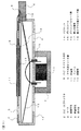
図3は、本発明の第2実施形態に係る複合型スピーカの図2と同様の断面図である。
【0041】
第1実施形態の複合型スピーカが、圧電体11をスピーカプロテクタ2の前面に貼り付けた構造であったのに対し、本実施形態の複合型スピーカは、スピーカプロテクタ2の前面に圧電体11を、背面に第2圧電体17をそれぞれ貼り付けたものである。なお、前面および背面にそれぞれ貼り付けられた圧電体11および第2圧電体17は、双方の分極方向が同一となるように貼り付けられている。
【0042】
第1実施形態と同様に、圧電体11はプラス端子リード線9によってスピーカプラス端子7と電気的に接続され、スピーカプロテクタ2は、マイナス端子リード線10によってスピーカマイナス端子8と電気的に接続されている。第2圧電体17は、第2プラス端子リード線18によってスピーカマイナス端子8と電気的に接続されている。つまり、圧電体11と第2圧電体17の分極方向が同じであるので、それぞれに対し互いに逆極性の電圧を印加することにより、一方が伸長すれば、他方が収縮する伸縮運動を行う。この圧電体11および第2圧電体17の伸縮運動によって、スピーカプロテクタ2は「バイモルフ振動板」として屈曲運動を行うこととなり、音波が発生する。
【0043】
このように、第2実施形態の複合型スピーカは、スピーカプロテクタ2の前面および背面の両面にそれぞれ圧電体11および第2圧電体17を貼り付けて「バイモルフ型の圧電スピーカ」を構成したものであり、第1実施形態の複合型スピーカと同様の効果、すなわち、広い周波数帯域に渡る良好な特性の確保、薄型化および省スペース化、製品コストおよび製造コストの抑制、並びに、部品点数の削減による製品の低コスト化を実現できると共に、第1実施形態の複合型スピーカよりも圧電スピーカの音圧を増大させることができる。
【0044】
具体的な製造工程については、スピーカプロテクタ2の両面にそれぞれ圧電体11および第2圧電体17を貼り付け、プラス端子リード線9、第2プラス端子リード線18およびマイナス端子リード線10をアセンブリする工程と、各リード線とスピーカプラス端子7およびスピーカマイナス端子8とを、スピーカプロテクタ2をフレーム12組み込み時に圧着する工程とが追加されることになり、製造が容易で製造コストを抑えることができる。
【0045】
なお、第2実施形態の複合型スピーカにおいては、圧電体11および第2圧電体17の双方の分極方向が同一となるように、これらをスピーカプロテクタ2の前面および背面に貼り付け、圧電体11および第2圧電体17に対して互いに逆極性の信号を印加することにより、バイモルフ型の圧電スピーカを構成したが、圧電体11および第2圧電体17の互いの分極方向が異なるように、スピーカプロテクタ2の前面および背面にそれぞれ貼り付け、双方に対して同極性の信号を印加するようにしても良い。
【0046】
(変形例)
上記の第1〜第2の実施形態は、本発明を具体化した例を示すものである。したがって、本発明はこれらの実施形態に限定されるものではなく、本発明の趣旨を外れることなく種々の変形が可能であることは言うまでもない。
【0047】
【発明の効果】
以上説明したように、本発明の複合型スピーカによれば、広い周波数帯域にわたって良好な音響特性を確保すると共に、より一層の省スペース化、並びに製造コストおよび製品コストの低減を図ることができる。
【図面の簡単な説明】
【図1】(a)は本発明の第1実施形態に係る複合型スピーカを背面から見た外観図、(b)は正面から見た外観図である。
【図2】第1実施形態の複合型スピーカについて図1(a)におけるA−A’に沿った断面図である。
【図3】本発明の第2実施形態に係る複合型スピーカの図1(a)におけるA−A’に沿った断面図である。
【図4】(a)は従来のコーンスピーカを背面から見た外観図、(b)は正面から見た外観図である。
【図5】従来のコーンスピーカについて図4(a)におけるB−B’でカットした断面図である。
【符号の説明】
1,101 スピーカ本体
2,102 スピーカプロテクタ
3,103 ヨーク
4,104 背面音孔
5,105 前面音孔
6,106 端子台
7,107 スピーカプラス端子
8,108 スピーカマイナス端子
9 プラス端子リード線
10 マイナス端子リード線
11 圧電体
12,112 フレーム
13,113 マグネット
15,115 ボイスコイル
16,116 ボイスコイルリード線
17 第2圧電体
18 第2プラス端子リード線[0001]
BACKGROUND OF THE INVENTION
The present invention relates to a composite type speaker that is a combination of a dynamic speaker and a piezoelectric speaker. In particular, the present invention can ensure good reproduction characteristics over a wide frequency band, and further save space, as well as manufacturing cost and product cost. The present invention relates to a composite speaker that can reduce the noise.
[0002]
[Prior art]
[Patent Document 1]
JP 2000-78691 A [Patent Document 2]
Patent No. 2010415 [Patent Document 3]
As an example of a conventional dynamic speaker, the structure of a cone speaker is shown in FIGS. 4 and 5. FIG. 4A is an external view of the conventional cone speaker as viewed from the back, FIG. 4B is an external view of the cone speaker as viewed from the front, and FIG. 5 is a BB ′ line in FIG. 4A. FIG.
[0003]
The basic structure of the speaker body 101 includes a voice coil 115 for generating a driving force, a magnetic circuit (magnet 114) and a
[0004]
A disk-
[0005]
[Problems to be solved by the invention]
In the dynamic speaker having the above-described structure, the frequency characteristic of the sound pressure is closely related to the speed characteristic of the
[0006]
However, when mounting on a device with limited space such as a portable device, it is difficult to secure a space for mounting a plurality of speaker units. Therefore, a combination of a dynamic speaker and a piezoelectric speaker has been proposed that saves space and ensures good frequency characteristics over a wide frequency band.
[0007]
For example, in Patent Document 1 (Japanese Patent Laid-Open No. 2000-78691), a cone diaphragm is provided for the purpose of providing good acoustic characteristics up to an ultra high range and providing input resistance even in a place where heat dissipation conditions are poor. A composite speaker having a structure including a dynamic speaker and a piezoelectric speaker disposed in a center cap portion of the dynamic speaker is disclosed. The piezoelectric speaker has a vibrating body inside. Therefore, the dynamic speaker has its own cone diaphragm, and the piezoelectric speaker also has its own vibrator.
[0008]
In Patent Document 2 (Patent No. 2010415 specification), a ceramic disk of a piezoelectric speaker and each conical shape are used by using a cone diaphragm as a reflecting surface without applying an excessive load to the moving coil of the dynamic speaker. There is disclosed a composite speaker having a structure including a piezoelectric speaker held by a support, which makes it possible to fully utilize sound waves from the rear radiated by a diaphragm.
[0009]
Patent Document 3 (Japanese Patent Application Laid-Open No. 11-331976) discloses a baffle (a barrier that blocks the sound emitted from the front and back surfaces of the diaphragm from being mixed together) from the viewpoint of improving the timbre of the piezoelectric speaker. A composite speaker having a structure in which a dynamic speaker is attached, an acoustic diaphragm is disposed in a front region of the dynamic speaker, and a piezoelectric vibrator is attached to the acoustic diaphragm is disclosed.
[0010]
However, since all of the conventional composite speakers disclosed in
[0011]
The present invention has been made in view of the above-described conventional circumstances, and an object of the present invention is to provide a composite that can ensure good acoustic characteristics over a wide frequency band and further save space. It is to provide a type speaker.
[0012]
Another object of the present invention is to provide a composite speaker in which a dynamic speaker and a piezoelectric speaker are combined with a simpler structure.
[0013]
Still another object of the present invention is to provide a composite speaker that has a small number of parts, is easy to manufacture, and can be reduced in cost.
[0014]
Other objects of the present invention which are not specified here will become apparent from the following description and the accompanying drawings.
[0015]
[Means for Solving the Problems]
(1) The composite speaker according to the first aspect of the present invention is:
A composite speaker that combines a dynamic speaker and a piezoelectric speaker,
The dynamic speaker includes a protector for protecting the diaphragm provided in front of the diaphragm,
The piezoelectric speaker has a piezoelectric body attached to the front surface or the back surface of the protector, and is configured such that the protector operates as a diaphragm of the piezoelectric speaker by the expansion and contraction of the piezoelectric body.
The application of the signal to the dynamic speaker and the application of the signal to the piezoelectric speaker are performed through a common terminal .
[0016]
(2) In the composite speaker according to the first aspect of the present invention , a piezoelectric body is attached to the front surface or the back surface of the protector for protecting the diaphragm provided in front of the diaphragm of the dynamic speaker, and the expansion and contraction of the piezoelectric body is performed. The protector is configured to operate as a diaphragm of the piezoelectric speaker by movement. In other words, the protector included in the dynamic speaker and the piezoelectric body attached to the front or back of the protector constitute the piezoelectric speaker, and the protector functions as a diaphragm of the piezoelectric speaker. For this reason, by using the piezoelectric speaker for a high-frequency sound signal, an improvement in the high-frequency characteristics can be expected, and thus good acoustic characteristics can be secured over a wide frequency band.
[0017]
Further, the thickness of the composite speaker is the same as that of the dynamic speaker when the piezoelectric body is attached to the back surface of the protector, and even when the piezoelectric body is attached to the front surface of the protector. Therefore, it is possible to further reduce the thickness and space as compared with the conventional composite speaker.
[0018]
Furthermore, since the protector is used as a diaphragm of the piezoelectric speaker, and the application of the signal to the dynamic speaker and the application of the signal to the piezoelectric speaker are performed through a common terminal , the dynamic speaker and the piezoelectric speaker Product costs can be reduced by sharing parts. In addition, since the structure is simpler than that of a conventional composite speaker, the number of parts can be significantly reduced, and the cost of the product can be reduced. And since it can be configured simply by attaching the piezoelectric body to the configuration of the conventional dynamic speaker having a protector for protecting the diaphragm , the specific steps for manufacturing the piezoelectric body and the lead wire connecting process are also possible. As a result, the manufacturing is easy and the manufacturing cost can be reduced.
[0019]
(3) In the composite speaker according to the first aspect of the present invention, it is preferable that the piezoelectric body is attached to a central portion of the protector. By doing so, the dynamic speaker and the piezoelectric speaker are arranged coaxially, and the central axes of the directivity characteristics of these speakers are aligned coaxially, so that the center position of the sound image and the size of the sound image by sound reproduction are reduced. It does not change so much until reaching the high sound range, and an accurate sound image localization is obtained, and the acoustic characteristics up to the high sound range are improved.
[0020]
(4) The composite speaker according to the second aspect of the present invention is
A composite speaker that combines a dynamic speaker and a piezoelectric speaker,
The dynamic speaker includes a protector for protecting the diaphragm provided in front of the diaphragm,
The piezoelectric speaker has first and second piezoelectric bodies attached to a front surface and a back surface of the protector, respectively, and the protector moves the piezoelectric speaker by the expansion and contraction movement of the first and second piezoelectric bodies. Configured to operate as a bimorph vibrator
The application of the signal to the dynamic speaker and the application of the signal to the piezoelectric speaker are performed through a common terminal .
[0021]
(5) In the composite speaker according to the second aspect of the present invention, mounting the front and the the back first and second piezoelectric said protector, the protector by stretching movement of the first and second piezoelectric Is configured to operate as a bimorph vibrating body of the piezoelectric speaker, so that the protector and the first and second piezoelectric bodies attached to the front and back surfaces of the protector constitute a bimorph type piezoelectric speaker. . Therefore, the same effect as the composite speaker according to the first aspect of the present invention, that is, ensuring good acoustic characteristics over a wide frequency band, reducing the thickness and space, reducing the product cost and manufacturing cost, and the number of parts It is possible to reduce the cost of products by reducing the cost. Further, there is an advantage that the sound pressure of the piezoelectric speaker can be increased as compared with the composite speaker according to the first aspect of the present invention.
[0022]
(6) In the composite speaker according to the second aspect of the present invention, preferably, when the first and second piezoelectric bodies are attached so that their polarization directions are opposite to each other, A signal having the same polarity is applied to the second piezoelectric body. When the first and second piezoelectric bodies are attached so that their polarization directions are the same, signals having opposite polarities are applied to the first and second piezoelectric bodies. This is because a bimorph type piezoelectric speaker can be obtained.
[0023]
In the composite speaker according to the second aspect of the present invention, it is preferable that the piezoelectric body is attached to a central portion of a metal protector. By doing so, the dynamic speaker and the piezoelectric speaker are arranged coaxially, and the central axes of the directivity characteristics of these speakers are aligned coaxially, so that the center position of the sound image and the size of the sound image by sound reproduction are reduced. It does not change so much until reaching the high sound range, and an accurate sound image localization is obtained, and the acoustic characteristics up to the high sound range are improved.
[0024]
DETAILED DESCRIPTION OF THE INVENTION
DESCRIPTION OF EXEMPLARY EMBODIMENTS Hereinafter, preferred embodiments of the invention will be described in the order of [first embodiment] and [second embodiment] with reference to the accompanying drawings.
[0025]
[First Embodiment]
First, a composite speaker according to a first embodiment of the present invention will be described with reference to FIGS. FIG. 1A is an external view of the composite speaker of the present embodiment as viewed from the back, FIG. 1B is an external view of the composite speaker of the present embodiment as viewed from the front, and FIG. It is sectional drawing along line AA '.
[0026]
In the composite speaker according to the present embodiment, the basic structure of the
[0027]
The
[0028]
A disc-shaped
[0029]
A circular flat plate-like piezoelectric body 11 is attached to the center portion of the
[0030]
Next, the operation of the complex speaker of the first embodiment having the above structure will be described.
[0031]
First, when a predetermined signal voltage is applied to the loudspeaker plus
[0032]
On the other hand, in the piezoelectric speaker, the same voltage is applied to the piezoelectric body 11 via the plus
[0033]
As described above, in the composite speaker of the first embodiment, the
[0034]
In addition, since the piezoelectric body 11 is attached to the center of the
[0035]
The thickness (total thickness) of the composite speaker according to the first embodiment is simply the thickness of the piezoelectric body 11 attached to the front surface of the
[0036]
Furthermore, since the
[0037]
Looking at a specific manufacturing process, a composite speaker can be configured by simply pasting the piezoelectric body 11 to the configuration of the conventional dynamic speaker. Therefore, the process of pasting the piezoelectric body 11, the speaker plus
[0038]
In the composite speaker according to the first embodiment, the piezoelectric body 11 is attached to the front surface of the
[0039]
As a sound signal supplied to the piezoelectric speaker, a high sound range sound signal may be supplied via a high sound range filter. As a result, the sound signal in the high sound range is acoustically converted by the piezoelectric speaker, which is a low impedance element, so that the sound pressure sensitivity proportional to the frequency of the sound signal can be obtained in the high sound range, and the sound characteristics up to the high sound range are good. It becomes.
[0040]
[Second Embodiment]
FIG. 3 is a cross-sectional view similar to FIG. 2 of the composite speaker according to the second embodiment of the present invention.
[0041]
The composite speaker of the first embodiment has a structure in which the piezoelectric body 11 is attached to the front surface of the
[0042]
As in the first embodiment, the piezoelectric body 11 is electrically connected to the speaker plus terminal 7 by the plus
[0043]
As described above, the composite speaker according to the second embodiment is a “bimorph piezoelectric speaker” in which the piezoelectric body 11 and the second
[0044]
As for a specific manufacturing process, the piezoelectric body 11 and the second
[0045]
In the composite speaker of the second embodiment, the piezoelectric body 11 and the second
[0046]
(Modification)
Said 1st-2nd embodiment shows the example which actualized this invention. Therefore, the present invention is not limited to these embodiments, and it goes without saying that various modifications can be made without departing from the spirit of the present invention.
[0047]
【The invention's effect】
As described above, according to the composite speaker of the present invention, it is possible to ensure good acoustic characteristics over a wide frequency band, further save space, and reduce manufacturing costs and product costs.
[Brief description of the drawings]
FIG. 1A is an external view of a composite speaker according to a first embodiment of the present invention as viewed from the back, and FIG. 1B is an external view of the composite speaker as viewed from the front.
FIG. 2 is a cross-sectional view taken along the line AA ′ in FIG. 1A for the composite speaker of the first embodiment.
FIG. 3 is a cross-sectional view taken along line AA ′ in FIG. 1A of a composite speaker according to a second embodiment of the present invention.
4A is an external view of a conventional cone speaker viewed from the back, and FIG. 4B is an external view of the conventional cone speaker viewed from the front.
FIG. 5 is a cross-sectional view of a conventional cone speaker cut along BB ′ in FIG.
[Explanation of symbols]
1,101 speaker body 2,102 speaker protector 3,103 yoke 4,104 back sound hole 5,105 front sound hole 6,106 terminal block 7,107 speaker plus terminal 8,108 speaker minus terminal 9 plus
Claims (6)
前記ダイナミックスピーカは、振動板の前方に設けられた当該振動板保護用のプロテクタを備えており、
前記圧電スピーカは、前記プロテクタの前面または背面に取り付けられた圧電体を有していると共に、当該圧電体の伸縮運動によって当該プロテクタが前記圧電スピーカの振動板として動作するように構成されており、
前記ダイナミックスピーカへの信号の印加と前記圧電スピーカへの信号の印加は、共通の端子を介して行われることを特徴とする複合型スピーカ。A composite speaker that combines a dynamic speaker and a piezoelectric speaker,
The dynamic speaker includes a protector for protecting the diaphragm provided in front of the diaphragm,
The piezoelectric speaker has a piezoelectric body attached to the front surface or the back surface of the protector, and is configured so that the protector operates as a diaphragm of the piezoelectric speaker by the expansion and contraction of the piezoelectric body.
The composite speaker, wherein the application of the signal to the dynamic speaker and the application of the signal to the piezoelectric speaker are performed through a common terminal .
前記ダイナミックスピーカは、振動板の前方に設けられた当該振動板保護用のプロテクタを備えており、
前記圧電スピーカは、前記プロテクタの前面および背面にそれぞれ取り付けられた第1および第2の圧電体を有していると共に、当該第1および第2の圧電体の伸縮運動によって当該プロテクタが前記圧電スピーカのバイモルフ振動体として動作するように構成されており、
前記ダイナミックスピーカへの信号の印加と前記圧電スピーカへの信号の印加は、共通の端子を介して行われることを特徴とする複合型スピーカ。A composite speaker that combines a dynamic speaker and a piezoelectric speaker,
The dynamic speaker includes a protector for protecting the diaphragm provided in front of the diaphragm,
The piezoelectric speaker has first and second piezoelectric bodies attached to a front surface and a back surface of the protector, respectively, and the protector moves the piezoelectric speaker by the expansion and contraction movement of the first and second piezoelectric bodies. Configured to operate as a bimorph vibrator
The composite speaker according to claim 1, wherein the application of the signal to the dynamic speaker and the application of the signal to the piezoelectric speaker are performed through a common terminal .
Priority Applications (1)
| Application Number | Priority Date | Filing Date | Title |
|---|---|---|---|
| JP2002309761A JP4006636B2 (en) | 2002-10-24 | 2002-10-24 | Composite speaker |
Applications Claiming Priority (1)
| Application Number | Priority Date | Filing Date | Title |
|---|---|---|---|
| JP2002309761A JP4006636B2 (en) | 2002-10-24 | 2002-10-24 | Composite speaker |
Publications (2)
| Publication Number | Publication Date |
|---|---|
| JP2004147077A JP2004147077A (en) | 2004-05-20 |
| JP4006636B2 true JP4006636B2 (en) | 2007-11-14 |
Family
ID=32455476
Family Applications (1)
| Application Number | Title | Priority Date | Filing Date |
|---|---|---|---|
| JP2002309761A Expired - Fee Related JP4006636B2 (en) | 2002-10-24 | 2002-10-24 | Composite speaker |
Country Status (1)
| Country | Link |
|---|---|
| JP (1) | JP4006636B2 (en) |
Cited By (1)
| Publication number | Priority date | Publication date | Assignee | Title |
|---|---|---|---|---|
| WO2019098487A1 (en) * | 2017-11-20 | 2019-05-23 | 주식회사 비에스이 | Hybrid speaker |
Families Citing this family (19)
| Publication number | Priority date | Publication date | Assignee | Title |
|---|---|---|---|---|
| JPH0759221B2 (en) * | 1989-08-04 | 1995-06-28 | 三菱電機ホーム機器株式会社 | Rice cooker control device |
| KR100646041B1 (en) * | 2005-01-20 | 2006-11-14 | 이인희 | A Speaker embodying a stereo sound |
| JP2014086831A (en) * | 2012-10-23 | 2014-05-12 | Sharp Corp | Loudspeaker system and video display device |
| TWM492586U (en) * | 2014-06-18 | 2014-12-21 | Jetvox Acoustic Corp | Piezoelectric speaker |
| JP6177757B2 (en) * | 2014-08-18 | 2017-08-09 | アルムス コーポレーション | High-quality speakers using dynamic speakers and piezoelectric elements |
| KR200476280Y1 (en) * | 2014-08-18 | 2015-02-13 | 영보엔지니어링 주식회사 | High-quality sound speaker using piezoelectric element |
| KR101738902B1 (en) * | 2014-10-23 | 2017-05-25 | 주식회사 알머스 | High-quality sound speaker using dynamic speaker and piezoelectric element |
| US9686615B2 (en) | 2014-10-24 | 2017-06-20 | Taiyo Yuden Co., Ltd. | Electroacoustic converter and electronic device |
| JP5759641B1 (en) * | 2014-10-24 | 2015-08-05 | 太陽誘電株式会社 | Electroacoustic transducer and electronic device |
| TWM499720U (en) * | 2014-10-31 | 2015-04-21 | Jetvox Acoustic Corp | Piezoelectric ceramic dual-band earphone structure |
| JP5768198B1 (en) * | 2014-12-02 | 2015-08-26 | 太陽誘電株式会社 | Electroacoustic transducer |
| KR101515815B1 (en) * | 2014-12-23 | 2015-05-06 | 영보엔지니어링 주식회사 | Speaker using dynamic speaker and piezoelectric element |
| WO2016137200A1 (en) * | 2015-02-24 | 2016-09-01 | 주식회사 이노칩테크놀로지 | Sound output device |
| KR20160103489A (en) | 2015-02-24 | 2016-09-01 | 주식회사 모다이노칩 | Sound output apparatus |
| JP6461724B2 (en) * | 2015-06-05 | 2019-01-30 | 太陽誘電株式会社 | Piezoelectric sounder and electroacoustic transducer |
| JP5867975B1 (en) * | 2015-06-11 | 2016-02-24 | 株式会社メイ | Speaker and earphone |
| WO2018079583A1 (en) | 2016-10-28 | 2018-05-03 | ソニー株式会社 | Electroacoustic transducer and electroacoustic transducer device |
| KR101958260B1 (en) * | 2017-07-22 | 2019-03-15 | 부전전자 주식회사 | Hybrid micro-speaker with dynamic speaker and piezoelectric element |
| CN109714684A (en) * | 2017-10-26 | 2019-05-03 | 华一声学股份有限公司 | Point sound source loudspeaker |
-
2002
- 2002-10-24 JP JP2002309761A patent/JP4006636B2/en not_active Expired - Fee Related
Cited By (2)
| Publication number | Priority date | Publication date | Assignee | Title |
|---|---|---|---|---|
| WO2019098487A1 (en) * | 2017-11-20 | 2019-05-23 | 주식회사 비에스이 | Hybrid speaker |
| US11128948B2 (en) | 2017-11-20 | 2021-09-21 | Bse Co., Ltd. | Hybrid speaker |
Also Published As
| Publication number | Publication date |
|---|---|
| JP2004147077A (en) | 2004-05-20 |
Similar Documents
| Publication | Publication Date | Title |
|---|---|---|
| JP4006636B2 (en) | Composite speaker | |
| JP7377877B2 (en) | Multi-range speaker containing multiple diaphragms | |
| JP3972306B2 (en) | Speaker diaphragm and speaker using the diaphragm | |
| US7324655B2 (en) | Electroacoustic transducer | |
| EP2869593B1 (en) | Earphone device | |
| CN107409259B (en) | Electronic sound equipment changing device | |
| CN108513240B (en) | Electroacoustic transducer | |
| CN109309894B (en) | Electroacoustic transducer | |
| JP2002078079A (en) | Electroacoustic transducer | |
| JP2000233157A (en) | Vibration generator | |
| JP6177757B2 (en) | High-quality speakers using dynamic speakers and piezoelectric elements | |
| KR20030039926A (en) | Receiver United in Speaker | |
| JP3861123B2 (en) | Speaker device | |
| JP2004356868A (en) | Speaker | |
| JP2001224090A (en) | Passive radiator loudspeaker system | |
| KR101087493B1 (en) | A Hidden Magnetostrictive Speaker Embedded in Flat Panel Display | |
| JPH09215089A (en) | Sound wave radiator | |
| JP4075244B2 (en) | Speaker | |
| CN220108195U (en) | Sounding monomer, sounding module and electronic equipment | |
| JPH11308691A (en) | Loud speaker system | |
| WO2020158173A1 (en) | Electroacoustic transducer | |
| JP3924777B2 (en) | Flat speaker | |
| JPS5912700A (en) | Composite type speaker | |
| JP6875908B2 (en) | Electro-acoustic converter | |
| JPH11220783A (en) | Loud speaker with heat radiation hole and electrical appliance using the same |
Legal Events
| Date | Code | Title | Description |
|---|---|---|---|
| A621 | Written request for application examination |
Free format text: JAPANESE INTERMEDIATE CODE: A621 Effective date: 20050913 |
|
| A977 | Report on retrieval |
Free format text: JAPANESE INTERMEDIATE CODE: A971007 Effective date: 20070227 |
|
| A131 | Notification of reasons for refusal |
Free format text: JAPANESE INTERMEDIATE CODE: A131 Effective date: 20070410 |
|
| A521 | Written amendment |
Free format text: JAPANESE INTERMEDIATE CODE: A523 Effective date: 20070611 |
|
| TRDD | Decision of grant or rejection written | ||
| A01 | Written decision to grant a patent or to grant a registration (utility model) |
Free format text: JAPANESE INTERMEDIATE CODE: A01 Effective date: 20070802 |
|
| A61 | First payment of annual fees (during grant procedure) |
Free format text: JAPANESE INTERMEDIATE CODE: A61 Effective date: 20070815 |
|
| FPAY | Renewal fee payment (event date is renewal date of database) |
Free format text: PAYMENT UNTIL: 20100907 Year of fee payment: 3 |
|
| R150 | Certificate of patent or registration of utility model |
Free format text: JAPANESE INTERMEDIATE CODE: R150 |
|
| FPAY | Renewal fee payment (event date is renewal date of database) |
Free format text: PAYMENT UNTIL: 20110907 Year of fee payment: 4 |
|
| FPAY | Renewal fee payment (event date is renewal date of database) |
Free format text: PAYMENT UNTIL: 20120907 Year of fee payment: 5 |
|
| FPAY | Renewal fee payment (event date is renewal date of database) |
Free format text: PAYMENT UNTIL: 20130907 Year of fee payment: 6 |
|
| S111 | Request for change of ownership or part of ownership |
Free format text: JAPANESE INTERMEDIATE CODE: R313113 |
|
| R350 | Written notification of registration of transfer |
Free format text: JAPANESE INTERMEDIATE CODE: R350 |
|
| R250 | Receipt of annual fees |
Free format text: JAPANESE INTERMEDIATE CODE: R250 |
|
| LAPS | Cancellation because of no payment of annual fees |