JP4005964B2 - Piston ring inspection method and apparatus - Google Patents
Piston ring inspection method and apparatus Download PDFInfo
- Publication number
- JP4005964B2 JP4005964B2 JP2003368681A JP2003368681A JP4005964B2 JP 4005964 B2 JP4005964 B2 JP 4005964B2 JP 2003368681 A JP2003368681 A JP 2003368681A JP 2003368681 A JP2003368681 A JP 2003368681A JP 4005964 B2 JP4005964 B2 JP 4005964B2
- Authority
- JP
- Japan
- Prior art keywords
- piston
- ring
- piston ring
- peripheral surface
- outer peripheral
- Prior art date
- Legal status (The legal status is an assumption and is not a legal conclusion. Google has not performed a legal analysis and makes no representation as to the accuracy of the status listed.)
- Expired - Fee Related
Links
Images


Description
本発明は、例えば自動車用エンジン等に組み込まれる前のピストンを対象とし、このピストン外周にその軸線方向に所定間隔を隔てて形成されている複数のリング溝に組付けられたピストンリングの検査方法及びその装置に関する。 The present invention is directed to, for example, a piston before being incorporated in an automobile engine or the like, and an inspection method for piston rings assembled in a plurality of ring grooves formed at predetermined intervals in the axial direction on the outer periphery of the piston. And an apparatus for the same.
ピストンの複数のリング溝には、トップリング、セカンドリング、サイドレールアッパーリング、サイドレールロアーリング等の複数のピストンリングがピストンリング組付機等により組付けられる。その際、組付け忘れや各ピストンリング合口部の周方向位置が一致して直線上に並んでいるような組付け不良、さらには、組付け力等によってピストンリング自体が変形してその合口部の幅が所定値よりも変化するなどの異常事態が生じたままであると、ピストンをエンジンに組み込んだとき、ピストンリング本来の性能、つまり、ピストンとシリンダ内壁との間の気密性が損なわれたり、シリンダ内壁の潤滑油のかき落とし性能が不十分になったりしてエンジン動作に種々の弊害をもたらしかねない。そのため、ピストン外周面の複数のリング溝にピストンリングを組付けた後、各ピストンリングの有無の確認及び各ピストンリング合口部の周方向位置の確認並びに各ピストンリング合口部の幅の合否を判断する検査作業は必須不可欠である。 A plurality of piston rings such as a top ring, a second ring, a side rail upper ring, and a side rail lower ring are assembled in the plurality of ring grooves of the piston by a piston ring assembling machine or the like. At that time, forgetting to assemble, poor assembly where the circumferential positions of the piston ring joints are aligned and aligned, and the piston ring itself is deformed by the assembly force etc. If the abnormal condition such as the width of the cylinder changes beyond a predetermined value remains, the original performance of the piston ring, that is, the airtightness between the piston and the cylinder inner wall may be impaired when the piston is incorporated into the engine. Further, the scraping performance of the lubricating oil on the inner wall of the cylinder may be insufficient, which may cause various adverse effects on the engine operation. Therefore, after assembling the piston rings in the plurality of ring grooves on the outer peripheral surface of the piston, confirm the presence / absence of each piston ring, confirm the circumferential position of each piston ring joint, and determine whether the width of each piston ring joint is acceptable. Inspection work is essential.
かかるピストンリングの検査方法として、従来一般には、作業者がピストンリングの組付後のピストンを一つ一つ手に取って目視によりピストンリングの有無の確認、合口部の周方向位置の確認及び合口部の幅の合否判断が行われていた。 As a method for inspecting such a piston ring, in general, an operator generally picks each piston after assembly of the piston ring and visually confirms the presence or absence of the piston ring, confirms the circumferential position of the joint portion, and A pass / fail judgment was made on the width of the abutment.
しかし、上記したような従来の目視による検査方法の場合は、面倒な手数を要するだけでなく、検査時間が長くかかり、エンジンの組付ラインタクトに間に合わないため、ピストンリングの組付けが完了したピストンの多数を検査のためにストックしておくためのスペースの確保が必要になる。また、ピストンリングの有無及び合口部の周方向位置の確認は、一目するだけでよいので、熟練者でなくても可能であるが、合口部の幅の合否については、この種の作業経験並びに技術知識が豊富な熟練作業者でなければ正確に判定することができないという問題がある。 However, in the case of the conventional visual inspection method as described above, not only troublesome work is required, but also the inspection time takes a long time, and the assembly of the piston ring is completed because it is not in time for the assembly line tact of the engine. It is necessary to secure a space for stocking a large number of pistons for inspection. In addition, since it is only necessary to check the presence or absence of the piston ring and the circumferential position of the abutment portion, it is possible even for an unskilled person. There is a problem that it cannot be determined accurately unless it is a skilled worker with abundant technical knowledge.
本発明は上述の実情に鑑みてなされたもので、その目的は、ピストンリングの有無及び合口部の周方向位置の確認はもとより、合口部の幅の合否をも未熟練作業者であっても、容易かつ迅速に、しかも正確に判定することができるピストンリングの検査方法及びその装置を提供することにある。 The present invention has been made in view of the above-described circumstances, and its purpose is not only to confirm the presence / absence of the piston ring and the circumferential position of the abutment portion, but also to determine whether or not the width of the abutment portion is acceptable. An object of the present invention is to provide a piston ring inspection method and apparatus capable of easily, quickly and accurately determining.
上記目的を達成するために案出された本発明に係るピストンリングの検査方法は、ピストン外周にその軸線方向に所定間隔を隔てて形成した複数のリング溝に組付けられたピストンリングの検査方法であって、ピストンの側方位置から前記ピストンリング組付け位置に向けてピストン径方向に対して傾斜する方向の光を照射し、この光照射状態でピストンをその軸心周りに回転させてその外周面一周分の画像を前記のピストン側方位置からカメラで撮影することにより、ピストンリングの有無及び各ピストンリング合口部の周方向位置を確認するとともに、前記撮影画像のデータ処理により、各ピストンリング合口部の幅の合否を判定することを特徴としている。 An inspection method for a piston ring according to the present invention devised to achieve the above object is an inspection method for a piston ring assembled in a plurality of ring grooves formed at predetermined intervals in the axial direction on the outer periphery of the piston. Then, light in a direction inclined with respect to the piston radial direction is irradiated from the side position of the piston toward the piston ring assembly position, and in this light irradiation state, the piston is rotated around its axis to By taking an image of the entire circumference of the outer peripheral surface with a camera from the side position of the piston, the presence or absence of the piston ring and the circumferential position of each piston ring joint are confirmed, and each piston is processed by data processing of the captured image. It is characterized by determining pass / fail of the width of the ring joint portion.
また、上記と同一の目的を達成するために案出された本発明に係るピストンリングの検査装置は、ピストン外周にその軸線方向に所定間隔を隔てて形成した複数のリング溝に組付けられたピストンリングの検査装置であって、ピストンの側方位置に配置され前記ピストンリング組付け位置に向けてピストン径方向に対して傾斜する方向の光を照射する光源と、ピストンをその軸心周りに回転させるピストン回転機構と、前記ピストンの側方位置に配置されピストンの回転時にその外周面一周分の画像を撮影するカメラと、その撮影画像のデータ処理により各ピストンリング合口部の幅の合否判定画面を表示する手段とを備えていることを特徴としている。 Also, the piston ring inspection device according to the present invention devised to achieve the same object as described above is assembled to a plurality of ring grooves formed at predetermined intervals in the axial direction on the outer periphery of the piston. An inspection device for a piston ring, which is disposed at a side position of the piston and irradiates light in a direction inclined with respect to the piston radial direction toward the piston ring assembly position, and the piston around its axis Piston rotation mechanism that rotates, a camera that is arranged at a side position of the piston and that captures an image of the entire circumference of the outer periphery when the piston rotates, and a pass / fail determination of the width of each piston ring joint by data processing of the captured image And a means for displaying a screen.
上記のごとき特徴構成を有する本発明に係るピストンリングの検査方法及びその装置によれば、ピストンの側方位置から複数のピストンリングが組付けられた位置に向けてピストン径方向に対して傾斜方向の光を照射した状態でピストンをその軸心周りに回転させてピストン外周面一周分の画像をカメラ撮影することにより、ピストンリングが正常にリング溝内に組付けられているときとそうで無いときとで各ピストンリングの外周面における最強光照射部位が画像上の異なる位置に線状に写し出されるために、その画像上に写し出された線状部位の位置を観察するだけで、各ピストンリングそれぞれが対応するリング溝に所定どおり組付けられているか否か、つまり、各ピストンリングの有無及び各ピストンリング合口部の周方向位置を容易かつ迅速に確認することができる。しかも、撮影画像のデータ処理により得られたピストンリング合口部の幅を画面上に表示させる、あるいは、ピストンリング合口部の幅として許容範囲の数値を予め入力しておき、この許容範囲の数値と撮影画像のデータ処理による数値とを比較させてピストンリング合口部の幅の合否判定結果を画面上に表示させることによって、熟練や経験の少ない作業者であっても、合口部の幅の合否を極めて容易に、かつ正確に判定することができる。したがって、ピストンリング組付け位置に向けて光を照射して得られる画像及びその画像のデータ処理結果として画面上に表示される内容を観察し読み取るだけでよく、ピストンリングの検査作業の省力化、効率化を実現できるだけでなく、非常に信頼性の高い検査を実行できるという効果を奏する。 According to the piston ring inspection method and apparatus therefor according to the present invention having the above-described characteristic configuration, the direction of inclination with respect to the piston radial direction from the side position of the piston toward the position where a plurality of piston rings are assembled. When the piston ring is normally assembled in the ring groove, the piston is rotated around its axis and the image of the entire circumference of the piston is taken with the camera. Sometimes the strongest light irradiation site on the outer peripheral surface of each piston ring is linearly projected at different positions on the image, so it is only necessary to observe the position of the linear site projected on the image. Whether or not each is assembled in the corresponding ring groove as prescribed, that is, whether or not there is each piston ring and the circumferential position of each piston ring joint And it can be confirmed quickly. In addition, the width of the piston ring joint portion obtained by data processing of the captured image is displayed on the screen, or an allowable range value is input in advance as the width of the piston ring joint portion. By comparing the numerical value obtained by data processing of the captured image and displaying the result of pass / fail judgment of the piston ring joint part on the screen, even a skilled or less experienced operator can judge the joint part pass / fail result. It can be determined very easily and accurately. Therefore, it is only necessary to observe and read the image obtained by irradiating light toward the piston ring assembly position and the data displayed on the screen as a result of data processing of the image. Not only can efficiency be realized, but also an effect that a highly reliable inspection can be performed.
本発明に係るピストンリングの検査方法及び装置において、請求項2及び請求項5に記載のように、光照射位置及びカメラ撮影位置とは反対側からピストン外周面にリング押出用ローラを押圧させて各ピストンリングの光照射及びカメラ撮影側の外周面部分をピストン外周面の外方へ飛び出させて一周分の画像を撮影することにより、ピストンリングが正常にリング溝内に組付けられているときとそうで無いときとで画像上の異なる位置に線状に写し出される最強光照射部位とそれ以外の部位とのコントラストを大きくとれ、画面上でのピストンリングの有無及び各ピストンリング合口部の周方向位置の確認を一層容易、正確なものとすることができる。
In the piston ring inspection method and apparatus according to the present invention, as described in
また、照射光及び光源としては、どんなものであってもよいが、特に、請求項3及び6に記載のように、指向性の強いレーザー光及びレーザーを用いることが望ましく、この場合は、いかなる作業環境のもとでの検査であっても、ピストンリングの有無及び各ピストンリング合口部の周方向位置の確認並びに合口部の幅の合否判定という所定の検査を正確に行なうことができる。
The irradiation light and the light source may be any, but it is particularly desirable to use a laser beam and a laser having strong directivity as described in
以下、本発明の実施の形態を、図面を参照しながら説明する。
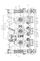
図1は本発明に係るピストンリングの検査方法に用いられる検査装置全体の概略平面図、図2はその要部の側面図、図3は同検査装置の要部の縦断正面図である。これら図1〜3において、1は床面に立設された架台2に図外のエアシリンダーを介して昇降自在に支持された装置フレームであり、この装置フレーム1にはベアリング3a付き筒状軸受部材3を介して縦軸4が回転自在に支承されている。
Hereinafter, embodiments of the present invention will be described with reference to the drawings.
FIG. 1 is a schematic plan view of the entire inspection apparatus used in the piston ring inspection method according to the present invention, FIG. 2 is a side view of the main part thereof, and FIG. 3 is a longitudinal front view of the main part of the inspection apparatus. 1 to 3,
この縦軸4の下端部には、水平搬送コンベア上に載荷されるパレット(図示省略する)にその軸心が縦向き姿勢の状態で収容保持されて検査装置内に搬入されてくるピストン5を挟持して所定高さ位置まで上昇させるピストンハンドユニット6が装備されているとともに、上端部には、ロータリーエンコーダ7が直結されている。また、この縦軸4はタイミングプーリー8,9及びタイミングベルト10を介して前記装置フレーム1に固設されたスピードコントロールモータ11に連動連結されており、このスピードコントロールモータ11と縦軸4と前記ハンドユニット6によりピストン5をその軸心、すなわち、縦軸心aの周りに駆動回転させるピストン回転機構が構成されている。
At the lower end portion of the vertical axis 4 is a
前記パレットによるピストン5の搬入口部12から検査後のピストン5の搬出口部13までのピストン移動経路における移動方向(図1の矢印A)に対して直交する方向の一側方に位置するフレーム部分1aには、前記ピストン5の外周面でその軸線方向に所定間隔を隔てて形成されている複数のリング溝14へのピストンリング組付け位置に向けてレーザー光LBを照射するレーザー(光源)15とそのレーザー光LBの照射されたピストン5外周面の画像を撮影するCCDカメラ16とが配置されている。
A frame located on one side in a direction orthogonal to the moving direction (arrow A in FIG. 1) in the piston moving path from the carry-in
また、前記レーザー15及びCCDカメラ16の配置側とは反対側、つまり、前記ピストン移動経路における移動方向Aに対して直交する方向の他側方位置にはエアシリンダー17を介してピストン移動経路に対し矢印x-y方向に接近離間移動可能な可動枠18が設けられており、この可動枠18には後述する一対のピストンリング押出用ローラ19,19が取付けられている。さらに、前記CCDカメラ16には、撮影画像をデータ処理してその処理結果等の画面を表示するPC20が接続されている。
Further, on the side opposite to the arrangement side of the
なお、図1、図2では、前記ピストン移動経路に搬入されてくるピストン5の3個を同時に検査できるように、ハンドユニット6付き縦軸4、レーザー15、CCDカメラ16及びピストンリング押出用の一対のローラ19,19のそれぞれをピストン移動方向Aに適宜間隔を隔てて3組、配置したものを示しているが、ピストン5を一つ一つ検査するように構成してもよく、以下においては一つのピストンリング検査装置の構成についてのみ説明する。
In FIG. 1 and FIG. 2, the vertical axis 4 with the
前記ピストン5の外周面に形成されている複数のリング溝14、具体的には、3つのリング溝14a〜14cには、図4(a),(b)に明示するように、トップリング21a、セカンドリング21b、サイドレールアッパーリング21c、サイドレールロアーリング21dと通称されている4つのピストンリング21がそれらの合口部21B(21a1,21b1,21c1,21d1)の周方向位置が少しづつずれるようにピストンリング組付機等を介して組付けられている。
As clearly shown in FIGS. 4 (a) and 4 (b), the
前記レーザー15は、該レーザー15から出射されたレーザー光LBがピストン径方向に対して傾斜する方向に指向されてピストン外周面を照射するような傾斜姿勢で前記フレーム部分1aに配置固定されているとともに、前記CCDカメラ16はレーザー光LBの最強光照射位置を略中心とするような画像が得られる傾斜姿勢で前記フレーム部分1aに配置固定されている。なお、レーザー15及びCCDカメラ16の傾斜角度は調整可能に構成されている。
The
前記ピストンリング押出用の一対のローラ19,19は、図5及び図6に示すように、前記可動枠18に固定のブラケット22の左右二箇所に支軸23,23を中心として揺動自在に枢支されたベルクランク24,24の先端部に自由回転可能に支承されているとともに、両ベルクランク24,24の他端部間には、一対のローラ19,19をストッパー25,25による制限位置まで互いに接近する方向に揺動付勢するバネ26が介在されており、これによって、可動枠18が図1の仮想線に示すように、ピストン移動経路側に接近移動して一対のローラ19,19がピストン5外周面に当接したとき、バネ25の付勢力に抗してベルクランク24,24が互いに離間する方向に揺動して一対のローラ19,19による弾性押圧力によって各ピストンリング21の光照射及びカメラ撮影側の外周面部分21Aをピストン5外周面の外方へ飛び出させるように構成している。
As shown in FIGS. 5 and 6, the pair of
次に、上記のように構成されたピストンリング検査装置による検査方法(手順)について説明する。
前記ピストン5を縦向き姿勢に収容保持しているパレットが水平搬送コンベアにより検査装置内部のピストン移動経路に搬入されて所定位置に停止されると、装置フレーム1が下降されて縦軸4下端部のハンドユニット6がピストン5を挟持し、続く装置フレーム1の上昇によって該ピストン5が図7に示すような所定高さ位置まで上昇される。
Next, an inspection method (procedure) by the piston ring inspection apparatus configured as described above will be described.
When the pallet holding and holding the
次いで、スピードコントロールモータ11が作動開始しその回転力がタイミングプーリー9,8及びタイミングベルト10を介して縦軸4に伝達されて該縦軸4及びその下端部に装備のハンドユニット6に挟持されたピストン5が縦軸心a周りに駆動回転される。このとき、可動枠18はエアシリンダー17を介して図1の仮想線に示すように、ピストン移動経路側に接近移動されて、この可動枠18に取付けられている一対のローラ19,19がピストン5の外周面に弾性的に押圧されるので、各ピストンリング21の光照射及びカメラ撮影側の外周面部分21Aは、図8に示すように、ピストン5外周面の外方へ飛び出され、この状態で縦軸4及びピストン5、ピストンリング21はロータリーエンコーダ7に設定されているパルス数に基づいてピストン外周面の一周分だけ駆動回転される。
Next, the
このような縦軸4、ピストン5及びピストンリング21の回転に並行してレーザー15が動作され、このレーザー15から出射されたレーザー光LBが図8に示すように、ピストン径方向に対して傾斜する方向からピストンリング組付け位置に向けて照射されるとともに、CCDカメラ16が作動してピストン5外周面一周分の画像が撮影されることになる。
The
ここで、前記レーザー光LBはピストンリング組付け位置の最も外方へ突出した部分を最も強く照射するので、各ピストンリング21(21a〜21d)が正常にリング溝14内に組付けられているときは、図9に示すように、ピストンリング21の最強光照射部位である飛び出しピストンリング21の外周面部分21Aの線L1が、その他の部位のうち最強光照射部位となる複数のリング溝14間のピストン外周面部分の線L2の一側に偏位して画像P上に写し出され、また、各ピストンリング21がリング溝14内に組付けられていないときは、図10に示すように、各リング溝14に対応する線L3が前記リング溝14間のピストン外周面部分の線L2の他側に偏位して画像P上に写し出されるために、その画像P上に写し出された線L1またはL3の線L2に対する位置を観察するだけで、各ピストンリング21それぞれが対応するリング溝14に所定どおり組付けられているか否か、つまり、各ピストンリング21の有無及び各ピストンリング合口部21B(21a1,21b1,21c1,21d1)の周方向位置を容易かつ迅速に確認することができる。
Here, since the laser beam LB irradiates the portion that protrudes outward most at the piston ring assembly position, each piston ring 21 (21a to 21d) is normally assembled in the
また、前記CCDカメラ16で撮影された一周分の画像はPC20に入力されデータ処理されてそのディスプレイには図11に示すようなモニター画面Sが表示される。このモニター画面S上に表示されたピストンリング合口部の幅w(図4の(b)参照)を確認するか、もしくは、ピストンリング合口部の幅として許容範囲の数値をPC20に予め入力しメモリに記憶入させておき、この記憶された許容範囲の数値と撮影画像のデータ処理による数値とを比較させてピストンリング合口部の幅の合否判定結果(OK又はNG)をモニター画面S上に表示させることによって、熟練や経験の少ない作業者であっても、合口部の幅の合否を極めて容易に、かつ正確に判定することができる。
Further, the one-round image taken by the
なお、前記ロータリーエンコーダ7への設定パルス数を変更することにより、外径寸法の異なる各種大きさ(径)のピストンを検査対象として、上記したような内容のピストンリングの検査に適用することが可能である。
It should be noted that by changing the number of pulses set to the
また、カメラとしては、上述したとおり、CCDカメラが最も好ましいが、デジタルカメラであっても、ビデオカメラであってもよい。 As described above, a CCD camera is most preferable as the camera, but it may be a digital camera or a video camera.
5 ピストン
14(14a〜14d) リング溝
15 レーザー(光源)
16 CCDカメラ
19 ピストンリング押出用ローラ
20 PC(撮影画像のデータ処理及び表示手段)
21(21a〜21d) ピストンリング
21A 飛び出し外周面部分
21B ピストンリング合口部
LB レーザー光
5 Piston 14 (14a-14d)
16
21 (21a to 21d)
Claims (6)
ピストンの側方位置から前記ピストンリング組付け位置に向けてピストン径方向に対して傾斜する方向の光を照射し、この光照射状態でピストンをその軸心周りに回転させてその外周面一周分の画像を前記のピストン側方位置からカメラで撮影することにより、各ピストンリングの有無及び各ピストンリング合口部の周方向位置を確認するとともに、前記撮影画像のデータ処理により、各ピストンリング合口部の幅の合否を判定することを特徴とするピストンリングの検査方法。 An inspection method for piston rings assembled in a plurality of ring grooves formed at predetermined intervals in the axial direction on the outer periphery of the piston,
Irradiate light in a direction inclined with respect to the piston radial direction from the side position of the piston toward the piston ring assembly position. In this light irradiation state, the piston is rotated around its axis to rotate around the outer circumferential surface. In addition to confirming the presence / absence of each piston ring and the circumferential position of each piston ring joint portion by photographing the image of the above from the piston side position, each piston ring joint portion is obtained by data processing of the photographed image. A method for inspecting a piston ring, comprising: determining whether the width of the piston ring is acceptable.
ピストンの側方位置に配置され前記ピストンリング組付け位置に向けてピストン径方向に対して傾斜する方向の光を照射する光源と、ピストンをその軸心周りに回転させるピストン回転機構と、前記ピストンの側方位置に配置されピストンの回転時にその外周面一周分の画像を撮影するカメラと、その撮影画像のデータ処理により各ピストンリング合口部の幅の合否判定画面を表示する手段とを備えていることを特徴とするピストンリングの検査装置。 A piston ring inspection device assembled to a plurality of ring grooves formed at predetermined intervals in the axial direction on the outer periphery of the piston,
A light source that is disposed at a side position of the piston and that emits light in a direction inclined with respect to the piston radial direction toward the piston ring assembly position; a piston rotation mechanism that rotates the piston around its axis; and the piston And a means for displaying a pass / fail judgment screen for the width of each piston ring joint by data processing of the captured image. An inspection device for a piston ring.
6. The piston ring inspection device according to claim 4, wherein the light source is a laser.
Priority Applications (1)
| Application Number | Priority Date | Filing Date | Title |
|---|---|---|---|
| JP2003368681A JP4005964B2 (en) | 2003-10-29 | 2003-10-29 | Piston ring inspection method and apparatus |
Applications Claiming Priority (1)
| Application Number | Priority Date | Filing Date | Title |
|---|---|---|---|
| JP2003368681A JP4005964B2 (en) | 2003-10-29 | 2003-10-29 | Piston ring inspection method and apparatus |
Publications (2)
| Publication Number | Publication Date |
|---|---|
| JP2005133598A JP2005133598A (en) | 2005-05-26 |
| JP4005964B2 true JP4005964B2 (en) | 2007-11-14 |
Family
ID=34646275
Family Applications (1)
| Application Number | Title | Priority Date | Filing Date |
|---|---|---|---|
| JP2003368681A Expired - Fee Related JP4005964B2 (en) | 2003-10-29 | 2003-10-29 | Piston ring inspection method and apparatus |
Country Status (1)
| Country | Link |
|---|---|
| JP (1) | JP4005964B2 (en) |
Families Citing this family (3)
| Publication number | Priority date | Publication date | Assignee | Title |
|---|---|---|---|---|
| JP5331529B2 (en) * | 2009-03-23 | 2013-10-30 | 日産自動車株式会社 | Method for detecting deviation of joint position of piston ring and deviation detection device |
| JP6114051B2 (en) * | 2013-02-07 | 2017-04-12 | 本田技研工業株式会社 | Work assembly apparatus and work assembly method |
| JP6237266B2 (en) * | 2014-01-27 | 2017-11-29 | トヨタ自動車株式会社 | Piston side rail shortage inspection device |
-
2003
- 2003-10-29 JP JP2003368681A patent/JP4005964B2/en not_active Expired - Fee Related
Also Published As
| Publication number | Publication date |
|---|---|
| JP2005133598A (en) | 2005-05-26 |
Similar Documents
| Publication | Publication Date | Title |
|---|---|---|
| JP6740089B2 (en) | Robot device, inspection device, generator inspection device, and inspection method | |
| JP6520216B2 (en) | Work inspection apparatus and method of manufacturing rolling bearing | |
| JP5014170B2 (en) | Work appearance inspection device | |
| JP2018194443A (en) | Appearance inspection device | |
| JP2019506345A (en) | Conveying device and rolling element detection system and detection method | |
| KR101672523B1 (en) | The visual inspection method of a lens module for a camera | |
| JP6936995B2 (en) | Appearance inspection device for three-dimensional objects | |
| JP4005964B2 (en) | Piston ring inspection method and apparatus | |
| JP5794895B2 (en) | Cylindrical appearance inspection device | |
| TW201915441A (en) | Inspection apparatus and inspection method | |
| KR102365598B1 (en) | Capsule inspection device | |
| JP4539387B2 (en) | Belt end face inspection device and inspection method | |
| JP2014151393A (en) | Work assembly apparatus and work assembly method | |
| JP7194055B2 (en) | Joint inspection method and joint inspection device | |
| JP2017198985A (en) | Device and method for confirming table tilting | |
| JP6690158B2 (en) | Inner surface inspection device and positioning method | |
| JP2003156453A (en) | Method of inspecting side face | |
| JP4065263B2 (en) | Knock pin press-fitting device and knock pin press-fitting method for piston ring detent | |
| JP6616812B2 (en) | Table tilting confirmation device and confirmation method | |
| JP5128344B2 (en) | Oil seal inspection device | |
| JP2010107220A (en) | Method and device for inspecting outer-peripheralurface of non-cylindrical body | |
| JP7107008B2 (en) | Inspection device and inspection method | |
| KR101230985B1 (en) | Apparatus for Examining External of Object | |
| JP2021004769A (en) | Inspection apparatus of substrate and inspection method of substrate | |
| KR102362155B1 (en) | Driving method of capsule inspection device |
Legal Events
| Date | Code | Title | Description |
|---|---|---|---|
| TRDD | Decision of grant or rejection written | ||
| A01 | Written decision to grant a patent or to grant a registration (utility model) |
Free format text: JAPANESE INTERMEDIATE CODE: A01 Effective date: 20070821 |
|
| A61 | First payment of annual fees (during grant procedure) |
Free format text: JAPANESE INTERMEDIATE CODE: A61 Effective date: 20070824 |
|
| R150 | Certificate of patent or registration of utility model |
Free format text: JAPANESE INTERMEDIATE CODE: R150 |
|
| FPAY | Renewal fee payment (event date is renewal date of database) |
Free format text: PAYMENT UNTIL: 20100831 Year of fee payment: 3 |
|
| FPAY | Renewal fee payment (event date is renewal date of database) |
Free format text: PAYMENT UNTIL: 20110831 Year of fee payment: 4 |
|
| FPAY | Renewal fee payment (event date is renewal date of database) |
Free format text: PAYMENT UNTIL: 20110831 Year of fee payment: 4 |
|
| FPAY | Renewal fee payment (event date is renewal date of database) |
Free format text: PAYMENT UNTIL: 20120831 Year of fee payment: 5 |
|
| LAPS | Cancellation because of no payment of annual fees |