JP4005500B2 - Laser marking method - Google Patents
Laser marking method Download PDFInfo
- Publication number
- JP4005500B2 JP4005500B2 JP2002376855A JP2002376855A JP4005500B2 JP 4005500 B2 JP4005500 B2 JP 4005500B2 JP 2002376855 A JP2002376855 A JP 2002376855A JP 2002376855 A JP2002376855 A JP 2002376855A JP 4005500 B2 JP4005500 B2 JP 4005500B2
- Authority
- JP
- Japan
- Prior art keywords
- laser
- oscillation
- photosensitive material
- marking
- laser beam
- Prior art date
- Legal status (The legal status is an assumption and is not a legal conclusion. Google has not performed a legal analysis and makes no representation as to the accuracy of the status listed.)
- Expired - Fee Related
Links
Images


Abstract
Description
【0001】
【発明の属する技術分野】
本発明は、感光材料にレーザー光を照射して、感光材料上に文字や記号等のマーキングパターンを形成するレーザーマーキング方法に関する。
【0002】
【従来の技術】
医療用Xレイフィルムなどの感光材料では、エッジ部分にメーカー名や品種、ロット等を識別可能となるように文字等を記録している。このようなXレイフィルムなどの感光材料への文字や記号等を記録するときに、感光材料にレーザー光(レーザービーム)を照射して、感光材料の表面に熱かぶりや変形を生じさせることによりドットを形成し、このドット配列によって文字や記号等のマーキングパターンを形成するマーキング技術が知られている。
【0003】
例えば、図14(A)及び図14(B)に示す如きXレイフィルム90では、レーザービームが照射されることにより、このレーザービームのエネルギーによって乳剤層に溶融、蒸散が生じる。この過程で膨張する乳剤層92の内部に多数の微小な気泡が生じ、ドットが形成される。
【0004】
図14(A)に示すように、視認性の高いドット94では、乳剤層92内に生じる多数の気泡によって表面が突状(凸状)となると共に、多数の微細な気泡間の境界膜で光の乱反射が助長され、ドット94の内外とで反射光量が大きく変化することに高くなる。
【0005】
このようなドット配列によって文字や記号を形成するときには、ドット径やドット間隔を適切に設定することが必要であるが、個々のドットに対する高い視認性、すなわち、ドット94に高い仕上り品質が要求される。
【0006】
このとき、例えば、レーザービームによって必要以上に乳剤層92にエネルギーを与えると、図14(B)に示すように、乳剤層16が溶融して開口し、支持体であるベース層96が露出したドット98が形成されてしまう。
【0007】
このようなドット98では、乳剤層92の光透過率が高いXレイフィルム90などでは、乳剤層92と露出したベース層96の識別が困難となるために視認できなくなる。すなわち、ドット98の視認性は極めて低いものとなってしまい、このドット98が含まれるドット配列によって形成された文字や記号等の視認性もきわめて低くなる。
【0008】
したがって、レーザービームを用いてXレイフィルムに視認性の高いドット(ドット94)を形成するときには、Xレイフィルムへのレーザービームの照射時間を適正に制御して、レーザービームのエネルギーによってXレイフィルムに適正な変形を生じさせるようにしている。
【0009】
このようにして個々のドットの視認性を高めることにより、ドット配列によって形成するマーキングパターンの視認性向上を図ることができる。
【0010】
ところで、レーザー光を発振するレーザー発振管では、駆動開始直後の出力ピークが高く、駆動を継続することにより徐々に出力が低下し、所定時間が経過することにより安定化して定常出力状態となる。
【0011】
このようなレーザー発振管を用いてドット配列による文字や、複数の文字を連続的に記録したマーキングパターンを形成すると、マーキング開始直後に形成したドットやこのドットの配列によって形成した文字の視認性が極めて低くなってしまう。すなわち、出力ピークが高い状態で感光材料にレーザービームを照射すると、乳剤層の溶融、蒸散が進行してベース層が露出してしまう。
【0012】
レーザービームを用いてマーキングを行うときに、レーザー発振管の駆動開始直後に生じる出力ピークの影響を防止する方法として、レーザー発振管をパルス駆動してマーキングを行うときに、シャッターを閉じた状態でレーザー発振管の駆動を開始し、この後に、シャッターを開いた状態で、実際のパルス駆動によるマーキングを行うことが提案されている(例えば、特許文献1参照。)。
【0013】
これにより、レーザー発振管の駆動開始直後に生じる出力ピークの影響を受けることなく、レーザービームを用いたマーキングが可能となるようにしている。
【0014】
【特許文献1】
特開2000−52069号公報
【0015】
【発明が解決しようとする課題】
しかしながら、レーザー発振管を連続してパルス駆動したときには、駆動開始直後に出力ピークが生じると共に、各駆動パルスによる駆動時にも、最初に出力のピークが現われて、定常状態の出力へ向けて徐々に出力が低下する。
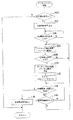
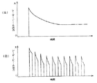
【0016】
すなわち、一つの文字ないし文字列を形成するときに、レーザー発振管を連続駆動したときには、図15(A)に示すように、レーザービームの出力は、駆動開始直後が極めて高く、時間経過と共に徐々に低下して定常状態で安定する。これに対して、レーザー発振管をパルス駆動したときには、図15(B)に示すように、各パルスにより駆動されたレーザー発振管の出力ピークは、徐々に低くなるが、各パルスによる駆動時においても、出力変化が生じ、出力は駆動開始直後が最も高く、また、出力が急激に低下する。
【0017】
このような、レーザー発振管から射出されるレーザービームの出力変化は、感光材料にドットを形成するときに、レーザービームのエネルギーが一部に集中してしまうことがある。
【0018】
これにより、例えば、例えばドットの中心部などに乳剤層の溶融、蒸散の進行を生じさせて、ベース層を露出させてしまったり、ドットの変形やドット径の縮小などを生じさせてしまう。このようなドットが形成されたときにも、ドットやドット配列によって形成する文字や記号などの視認性が低下してしまうと言う問題がある。
【0019】
本発明は上記事実に鑑みてなされたものであり、レーザー発振管等のレーザー発振手段の出力変化にかかわらず、感光材料に高品質で視認性の高いドット及びドット配列によるマーキングパターンを形成可能とするレーザーマーキング方法を提案することを目的とする。
【0020】
【課題を解決するための手段】
上記目的を達成するための請求項1に係る発明は、感光材料を搬送しながらレーザー発振手段によって発振させたレーザー光を照射して形成したドットの配列によって、前記感光材料上に文字、記号又は複数の文字、記号を並べた文字列のマーキングパターンを形成するレーザーマーキング方法であって、前記感光材料への前記レーザー光の照射に先立って前記レーザー発振手段によるレーザー光の発振を開始し、該レーザー発振手段の発振出力が安定した後に、偏向手段によって前記マーキングパターンに応じて前記レーザー光を偏向しながら前記感光材料へ照射することにより感光材料上に前記マーキングパターンを形成し、前記マーキングパターンの形成が終了した前記感光材料の搬送を停止した後、前記レーザー発振手段が発振を開始してから発振出力が安定するまでの時間より長く設定した時間が経過するまでに、新たな感光材料の搬送が開始されないときに、前記レーザー発振手段による前記レーザー光の発振停止を行う、ことを特徴とする。
【0021】
この発明によれば、感光材料へレーザー光を照射してドットを形成するのに先立って、レーザー発振手段を駆動してレーザー光の発振を開始し、レーザー発振手段の発振出力が安定した状態でレーザー光を感光材料へ照射する。
【0022】
このときに、偏向手段によってレーザー光を偏向することにより、感光材料にマーキングパターンに応じたドットを形成する。
【0023】
これにより、マーキングパターンを形成する個々のドットを均一な品質で感光材料に記録することができるので、感光材料に視認性の高いマーキングパターンを形成することができる。なお、レーザー発振手段によるレーザー光の発振を開始してから発振出力が安定するまでは、感光材料上にレーザー光を照射せずに、装置の内や外などの予め設定している一定部分、例えばダンパ等へ照射するものであれば良い。
【0024】
また、請求項2に係る発明は、感光材料を搬送しながらレーザー発振手段によって発振したレーザー光を照射して形成したドット配列によって、前記感光材料上に文字、記号又は複数の文字、記号を並べた文字列のマーキングパターンを形成するレーザーマーキング方法であって、前記レーザー発振手段によるレーザー光の発振を開始し、発振が開始された前記レーザー発振手段の発振出力が安定した状態で前記マーキングパターンが形成される前記感光材料上の位置が前記レーザー光の照射位置に達するように設定したタイミングで前記感光材料の搬送を開始して、前記照射位置に達した前記感光材料上へ偏向手段によって前記マーキングパターンに応じて前記レーザー光を偏向しながら照射して感光材料に前記マーキングパターンを形成し、前記マーキングパターンの形成が終了した前記感光材料の搬送を停止した後、前記レーザー発振手段の発振を開始してから発振出力が安定するまでの時間より長く設定した時間が経過するまでに、新たな感光材料の搬送が開始されないときに、前記レーザー発振手段による前記レーザー光の発振停止を行う、ことを特徴とする。
【0025】
この発明によれば、レーザー発振手段の出力が安定している状態で、感光材料上のマーキングパターンが形成される位置がレーザー光の照射位置に達するように、レーザー発振手段によるレーザー光の発振を開始した後、感光材料の搬送を開始する。これにより、レーザー発振手段の発振出力が安定している状態で、レーザー光を感光材料に照射してドットを形成することができるので、感光材料に視認性の高いマーキングパターンを形成することができる。
また、請求項1及び請求項2に係る発明では、感光材料の搬送を停止したときに、停止時間が短いときには、レーザー発振手段の発振を継続させる。
これにより、短時間の中断であれば、感光材料の搬送を開始することにより、感光材料へのマーキングが可能となるので、生産効率を低下させてしまうのを防止することができる。
【0026】
このような発明では、前記感光材料の搬送を開始するタイミングを、前記レーザー発振手段の発振を開始してからレーザー光の出力が安定するまでの時間とすることができる。
【0027】
また、本発明では、前記感光材料の搬送を開始するタイミングを、前記感光材料の前記マーキングパターンを形成する位置が前記レーザー光の照射位置に達する前に、前記レーザー発振手段によって発振したレーザー光の出力が安定するようにしたレーザー発振手段が発振を開始してからの時間とすることができ、これらの何れによっても、レーザー光を感光材料へ照射するときには、レーザー発振手段の発振出力が安定した状態とすることができる。
【0028】
また、本発明では、前記レーザー発振手段が発振を開始してから前記感光材料の搬送を開始する時間を、前記レーザー発振手段の出力変化に基づいて予め設定されているものであれば良い。また、本発明では、前記感光材料の搬送を開始するタイミングを、前記レーザー発振手段によって発振された前記レーザー光を検出して、該検出結果に基づいて判断してもよい。
【0032】
【発明の実施の形態】
以下、図面を参照しながら本発明の実施の形態を説明する。図1には、本実施の形態に適用したマーキング装置10の概略構成を示している。
【0033】
このマーキング装置10は、ロール状に巻き取られたXレイフィルム12を搬送する過程で、その表面にレーザービームLBを照射して、ドットないしドット配列を形成することにより、Xレイフィルム12に文字や記号ないし複数の文字や記号等による文字列等のマーキングパターンを形成する。
【0034】
本実施の形態に感光材料として適用したXレイフィルム12は、医療用の熱現像感光材料であり、図2(A)に示すように、PET(ポリエチレンテレフタレート)等を用いた支持体であるベース層14と、このベース層14の少なくとも一方の面に乳剤を塗布して形成した乳剤層16と、を含む多層状となっている。
【0035】
図1に示すように、マーキング装置10で処理されるXレイフィルム12は、例えば乳剤層16が外向きとなるように巻芯18に層状に巻き取られたロール20として装填される。
【0036】
マーキング装置10には、このロール20の装填位置近傍に小ロール22、24が対で配置されており、ロール20から引出されたXレイフィルム12は、まず、小ロール22に巻き掛けられる。
【0037】
この小ロール22、24の間には、サクションドラム26が設けられており、小ロール22、24及びサクションドラム26によって略U字状の搬送路が形成されており、Xレイフィルム12は、小ロール22、24の間で乳剤層16側が外向きとなるようにサクションドラム26の外周面に巻き掛けられる。
【0038】
サクションドラム26は、外周面に多数の小孔(図示省略)が形成されており、これらの小孔に負圧が供給されることにより、外周面に巻き掛けたXレイフィルム12を吸着保持する。また、マーキング装置10では、一例として、サクションドラム24が図示しない付勢手段の付勢力で、図1の紙面上方側へ移動するようになっており、これにより、マーキング装置10では、Xレイフィルム12に一定のテンションを付与するようにしている。
【0039】
マーキング装置10では、このサクションドラム26が図示しない駆動手段の駆動力によって所定の回転速度で回転駆動するようになっている。
【0040】
これにより、Xレイフィルム12は、サクションドラム26の回転速度に応じたライン速度でロール20から引出されながら搬送されて、小ロール24から送り出される。
【0041】
小ロール24の近傍には、パスロール28が設けられており、Xレイフィルム12は、このパスロール28に巻き掛けられることにより、搬送方向が上方へ向けて転換される。
【0042】
パスロール28の上方には、プリントロール30が設けられ、Xレイフィルム12は、プリントロール30に巻き掛けられることにより、水平方向へ向けられる。このとき、Xレイフィルム12に所定のテンションが付与されていることにより、Xレイフィルム12は、乳剤層16側が外向きとなるようにプリントロール30の周面に緊密に巻付けられる。
【0043】
マーキング装置10には、プリントロール30の水平方向側にパスロール32が設けられ、このパスロール32の下方に反転ロール34が設けられている。
【0044】
プリントロール30に巻き掛けられて送り出されるXレイフィルム12は、パスロール32に巻き掛けられることにより下方へ向けて方向転換され、さらに、反転ロール34に巻き掛けられた後に、巻芯36に巻付けられる。このときに、例えばロール20と同様に乳剤層16側が外向きとなるように巻芯36に巻き付けられる。
【0045】
一方、マーキング装置10には、作動を制御する巻取り制御装置38が設けられており、この巻取り制御装置38が、図示しない駆動源を制御して、サクションドラム26及び巻芯36等を回転駆動する。
【0046】
これにより、ロール20から引出されたXレイフィルム12は、プリントロール30に巻き掛けられた後に、巻芯36に達することにより、巻心36に層状に巻き取られる。
【0047】
また、サクションドラム26には、図示しないロータリーエンコーダが設けられており、ロータリーエンコーダの回転軸がサクションドラム26と一体で回転して、サクションドラム26の回転角に応じたパルス信号を出力する。巻取り制御装置38では、このパルス信号を計測することにより、Xレイフィルム12の搬送速度及び搬送長の検出が可能となっている。
【0048】
一方、マーキング装置10には、マーキングヘッド40及び、マーキングヘッド40の作動を制御するレーザー制御装置42が設けられている。
【0049】
レーザー制御装置42には、前記したロータリーエンコーダからサクションドラム26の回転に応じたパルス信号が入力されるようになっており、レーザー制御装置42では、このパルス信号に基づいてXレイフィルム12の搬送速度及び搬送長を監視しながらマーキングヘッド40の作動を制御する。
【0050】
図1及び図3に示すように、マーキングヘッド40内には、レーザー発振手段として設けられたレーザー発振管44及び、ビーム偏向手段として設けられたビーム偏向器46が配設されている。また、マーキングヘッド40は、図示しない集光レンズ等を備えた鏡筒48を備えている。
【0051】
本実施の形態に適用したレーザー発振管44は、CO2レーザーであり、レーザー制御装置42からの駆動信号に基づいて一定の発振波長のレーザービームLBを射出する。
【0052】
ビーム偏向器46は、例えばAOD(音響光学装置)を備えており、レーザー制御装置42から入力される偏向信号に基づいて、レーザー発振管44から射出されるレーザービームLBを、Xレイフィルム12の幅方向に沿って偏向しながら、プリントロール30に巻き掛けられるXレイフィルム12へ向けて射出する。
【0053】
このレーザービームLBは、鏡筒48を通過することにより、集光されてXレイフィルム12上で所定のスポット径となるように照射される。
【0054】
Xレイフィルム12は、レーザービームLBが照射されることにより乳剤層16に溶融、蒸散が生じる過程で多数の微小な気泡が生じる。Xレイフィルム12では、この多数の気泡が生じることにより、気泡間の境界膜で光の乱反射が生じ、未現像か現像済みか、あるいは濃度の濃淡にかかわらず、認識可能なドットが形成される。
【0055】
マーキング装置10では、このドットの配列により文字や記号等を形成すると共に、これらの文字や記号等を所定間隔で並べた文字列をマーキングパターンMPとしてXレイフィルム12に形成するようにしている。
【0056】
レーザー制御装置42は、レーザー発振管44へ駆動信号を出力することにより、このレーザー発振管44を駆動している状態で、Xレイフィルム12に形成すべきマーキングパターンMPに応じたパターン信号が、例えば巻取り制御装置38から入力されることにより、このパターン信号に応じてビーム偏向器46に偏向信号を出力する。
【0057】
これにより、プリントロール30に巻き掛けられたXレイフィルム12には、形成すべきマーキングパターンMPに応じてレーザービームLBが走査される。
【0058】
このとき、レーザー制御装置42は、サクションドラム26に設けているロータリーエンコーダーから出力されるパルス信号に基づいてXレイフィルム12の搬送長を監視して、搬送長が所定長さに達する毎にビーム偏向器46へ偏向信号を出力する。
【0059】
これにより、マーキング装置10では、Xレイフィルム12に所定間隔でマーキングパターンを形成するようにしている。すなわち、マーキング装置10では、図2(B)に示すように、Xレイフィルム12の搬送方向(図2(B)の矢印A方向)を副走査方向とし、レーザービームLBの走査方向を主走査方向として、レーザービームLBを照射することにより、ドット状のマーキングパターンMPを形成するようにしている。なお、図2(B)では、一例として5×5のドット配列でアルファベットを形成したマーキングパターンMPを示している。
【0060】
このようなXレイフィルム12を幅方向の中間部で裁断(スリット)するときには、このスリット位置であるスリットライン50(図2(B)、図3参照)を挟んだ両側のそれぞれにマーキングパターンMPを形成する。このとき、スリットライン50を挟んで天地の向きが逆となるマーキングパターンMPを形成することも可能である。
【0061】
Xレイフィルム12上に、視認性の高いマーキングパターンMPを形成するときには、個々のドットの視認性が高いことが必要であり、このようなドットを形成するためのレーザービームLBの照射時間は、レーザー発振管44の発振波長(レーザービームLBの波長)が、9μ帯(例えば9.3μm、9.6μmなどの波長)では、例えば1μsec〜15μsecの範囲となり、レーザー発振管44の発振波長が、10μm帯(例えば10.6μm)のときには、レーザービービームLBの照射時間を、例えば5μsec〜18μsecとすることができる。
【0062】
また、ドット径としては、0.18mm以上であることが好ましく、0.2mm以上であることがより好ましい。マーキングヘッド40では、このようなドット径を形成するために、Xレイフィルム12上に照射されるレーザービームLBのスポット径が約0.2mm以上となるようにしている。
【0063】
また、マーキングパターンMPの視認性は、ドット径のみならずドット間の中心間隔であるドットピッチも影響し、視認性の高いマーキングパターンMPを形成するために、マーキング装置10では、ドット径Dに対するドットピッチPの比であるP/Dが、1.5以下となるようにしている。
【0064】
一方、マーキング装置10では、Xレイフィルム12へのレーザービームLBの照射に先立って、レーザー発振管44を駆動し、所定のタイミングでXレイフィルム12の搬送を開始し、Xレイフィルム12の搬送長が所定長さに達する毎に、マーキングパターンMPのパターン信号に応じた偏向信号を、ビーム偏向器46へ出力することにより、レーザービームLBをXレイフィルム12に照射する。
【0065】
図4には、レーザー発振管44で発振するレーザービームLBの出力変化の一例を示している。マーキングヘッド40に設けているレーザー発振管44は、駆動信号が入力されることにより、レーザービームLBの発振を開始する。
【0066】
このとき、レーザー発振管44は、駆動開始直後がレーザービームLBの出力ピークとなり、時間経過に伴って出力が低下して、定常出力Paを出力する状態となる。なお、本実施の形態では、レーザー発振管44の定常出力状態を、レーザービームLBの出力変化が、定常値Paの±3%以内の状態としている。
【0067】
Xレイフィルム12では、出力が定常状態のレーザービームLBが照射されることにより適正なドットが形成されるようにレーザービームLBの照射時間が設定されていると、レーザービームLBの出力が大きいと、乳剤層16に必要以上に大きなエネルギーが供給されてしまい、ドットの視認性を低下させてしまう。
【0068】
すなわち、Xレイフィルム12では、レーザービームLBの出力が多き過ぎると、乳剤層16の溶融、蒸散が進行してしまい、ベース層14が露出するなどして、ドットの視認性が低下してしまう。
【0069】
このようなドットの視認性の低下は、ドット配列によって形成する文字や記号等にドットの欠落等による視認性の低下、仕上り品質の低下を生じさせてしまう。
【0070】
また、Xレイフィルム12に照射されるレーザービームLBは、定常出力状態で、図5(A)に示すように、強度がビーム中心(図5(A)で一点鎖線で示す)にピークを持つガウス分布となるガウシアンビームとなっている。このガウシアンビームでは、強度がピーク値に対して約86.5%下がったライン(図5(A)に破線で示す)がビーム径となっており、このビーム径に応じてXレイフィルム12にドットが形成される。
【0071】
これに対して、レーザー発振管44の駆動開始直後で出力が不安定な状態では、レーザービームLBの強度分布が、ガウシアンビームとならずに、例えば、図5(B)に示すように、複数の強度ピークを持つ分布となることがある。なお、図5(A)及び図5(B)では、横軸がビーム径方向となっている。
【0072】
このような強度分布のレーザービームLBがXレイフィルム12に照射されてしまうと、適正な位置に適正な数のドットが形成されなくなってしまう。
【0073】
これにより、例えば、マーキングパターンMPとして、図5(C)に示す如き文字列をXレイフィルム12に形成しようとしたときに、図5(D)に示すように、本来の位置と異なる位置に複数のドットが形成されてしまうことがある。
【0074】
このようなドット品質の低下の発生を防止するために、マーキング装置10では、Xレイフィルム12の加工処理に先立って、マーキングヘッド40のレーザー発振管44の駆動、すなわち、レーザービームLBの発振を開始し、レーザー発振管44の出力が安定するように予め設定した時間が経過した後に、Xレイフィルム12の加工処理、すなわち、Xレイフィルム12の搬送を開始するようにしている。また、Xレイフィルム12の搬送を停止して、Xレイフィルム12に対する加工処理を中断または終了するときには、所定時間経過するまでは、レーザー発振管44の発振動作を停止しないようにしている。
【0075】
このとき、マーキング装置10では、レーザー発振管44によるレーザービームLBの発振を開始してからXレイフィルム12の搬送を開始するまでの時間を、レーザー発振管44の出力が安定するまでの時間に基づいて設定している。
【0076】
マーキング装置10では、レーザー発振管44の駆動を開始してからXレイフィルム12の搬送を開始するまでの時間を、一例として、レーザー発振管44でレーザービームLBの発振を開始してから、レーザー発振管44の出力が定常状態に達して安定するまでの時間に1割程度の余裕を持たせた時間T0に設定している。
【0077】
これにより、マーキング装置10では、Xレイフィルム12を搬送しながらマーキングパターンMPを形成するときに、Xレイフィルム12に照射するレーザービームLBの出力が安定した状態となるようにしている。
【0078】
また、Xレイフィルム12の搬送を停止するときには、この時間T0に、さらに余裕を持たせた時間の間は、レーザー発振管44の作動を停止しないようにしており、これにより、ロール20等の交換をした後に、直ちにXレイフィルム12の加工処理を開始できるようにしている。
【0079】
図6に示すように、マーキングヘッド40には、鏡筒48内にレーザービームLBのエネルギーを吸収するダンパ52が設けられており、レーザー制御装置42は、レーザービームLBをXレイフィルム12に照射していない間は、レーザビームLBがダンパ52に照射されるようにビーム偏向器46に偏向信号を出力する。
【0080】
すなわち、レーザー制御装置42では、レーザー発振管44の駆動を開始すると、レーザービームLBがダンパ52に照射されるようにビーム偏向器46に偏向信号を出力し、Xレイフィルム12にマーキングパターンMPを形成するときに、ダンパ52に照射されているレーザービームLBが、Xレイフィル12の所定位置に照射されるように偏向信号を出力する。
【0081】
このときに、レーザー制御装置42では、偏向信号を適正に制御することにより、Xレイフィルム12上に適正なドットを形成できるようにレーザービームLBの照射時間を制御するようにしている。
【0082】
なお、レーザー発振管44は、レーザービームLBを発することにより発熱する。また、レーザービームLBが照射されるダンパ52は、レーザービームLBのエネルギーを吸収することにより発熱する。
【0083】
このために、マーキングヘッド40及びマーキングヘッド40に設けている鏡筒48には、例えば水冷方式等を用いた冷却手段が形成された一般的構成となっており、これにより、マーキング装置10では、マーキングヘッド40の温度上昇によるレーザービームLBの出力変化や、レーザービームLBの偏向位置の狂い等が生じるのを防止している。
【0084】
一方、AODを用いているビーム偏向器46では、偏向信号として入力される超音波周波数に応じて、レーザービームLBを偏向する。このとき、ビーム偏向器46では、例えば中心周波数f0に対して、入力された偏向信号の周波数fに応じて偏向角が変化する。この偏向角の変化に応じて、Xレイフィルム12上へのレーザービームLBの照射位置が、主操作方向であるXレイフィルム12の幅方向に沿って変化する。
【0085】
図7には、偏向信号として入力される周波数fに対する、ビーム偏向器46に用いられるAODの偏向効率の概略を示している。ビーム偏向器46(AOD)では、周波数fが中心周波数f0の近傍で偏向効率の変化が少なく、略平坦となっている。これに対して、周波数fが中心周波数f0に対して大きく変化すると、偏向効率が急激に低下する。
【0086】
このような偏向効率の低下は、レーザービームLBに減衰を生じさせ、視認性の高いドットを形成することが困難となり、ドット欠落等のマーキング不良を生じさせる。
【0087】
これを防止するために、レーザー制御装置42では、中心周波数f0の近傍で、偏向効率の変化が少なく略平坦となっている領域の平均偏向効率Peaに対して、例えば偏向効率Peが±10%の範囲(図7で二点鎖線で示す範囲)の周波数である周波数faから周波数fbの範囲を使用するようにしている。また、マーキングヘッド40は、この周波数fa〜fbの範囲で偏向されたレーザービームLBが、Xレイフィルム12上でマーキングパターンMPを形成すべき領域に照射されるように設けられている。
【0088】
これにより、マーキング装置10では、Xレイフィルム12上に均一なドットの形成が可能となっている。なお、レーザービームLBの偏向は、偏向効率Peが、平均偏向効率Peaに対して±10%の範囲で使用することが好ましいが、レーザーマーキングを行うときの偏向効率Peの実用域としては、平均偏向効率Peaに対して、+10%〜−30%の範囲とすることができるので、少なくともこの偏向効率Peの範囲でレーザービームLBの偏向を行うように設定されていることが好ましい。
【0089】
このように構成されているマーキング装置10では、パターン信号に基づいた偏向信号を用いてマーキングパターンMPを形成するようにしているため、パターン信号を変更することにより、Xレイフィルム12に形成するマーキングパターンMPを容易に変更することができる。
【0090】
すなわち、マーキング装置10では、Xレイフィルム12に照射するレーザービームLBによって形成するドット配列によってマーキングパターンMPを形成するようにしているために、Xレイフィルム12に記録したいマーキングパターンMPに応じたパターン信号を、レーザー制御装置42へ入力することにより、任意の文字や記号等をマーキングパターンMPとして形成することができると共に、Xレイフィルム12に形成するマーキングパターンMPの一部ないし全部を容易に変更することができるようになっている。
【0091】
以下に、本実施の作用として、マーキング装置10によるXレイフィルム12へのマーキングを説明する。
【0092】
図8には、マーキング装置10でXレイフィルム12に対してマーキング処理(加工処理)を行うときの処理の概略を示している。
【0093】
マーキング装置10では、例えば上位の生産管理装置等からXレイフィルム12に対するマーキング加工が指示されたり、ロール20が装填された状態で運転スイッチが操作されるなどして、処理開始要求が入力されることにより、図8に示すフローチャートの最初のステップ100で肯定判定されて、Xレイフィルム12に対するマーキング加工を開始する。
【0094】
マーキング装置10に設けている巻取り制御装置38では、ステップ100で肯定判定されることにより、ステップ102へ移行して、まず、レーザー制御装置42へ、レーザー発振管44の作動を要求する発振開始信号を出力する。
【0095】
図9には、レーザー制御装置42でのマーキングヘッド40を用いたマーキング処理の概略を示している。
【0096】
このフローチャートでは、最初のステップ120で、巻取り制御装置38から発振開始信号が入力されたか否かを確認しており、前記した図8のステップ102で、巻取り制御装置38がレーザー制御装置42へ発振開始信号を出力することにより、このフローチャートのステップ120で肯定判定する。
【0097】
これにより、ステップ122へ移行して、レーザー発振器44へ駆動信号を出力して、レーザー発振器44でのレーザービームLBの発振を開始する。このとき、レーザー制御装置42では、レーザービームLBが鏡筒48内に設けているダンパ52へレーザービームLBが照射されるようにビーム偏向器46へ偏向心を出力する。
【0098】
次のステップ124では、レーザー発振器44によるレーザービームLBの発振を開始してからの経過時間が、予め設定している時間T0に達しか否かを確認し、経過時間が時間T0に達して、ステップ124で肯定判定されると、ステップ126へ移行して、巻取り制御装置38へ処理開始信号を出力する。
【0099】
このときの時間T0は、レーザー発振管44で発振したレーザービームLBの出力が定常状態で安定するまでの時間であり、ここから、レーザー制御装置42では、レーザービームLBの出力が安定するタイミングで、巻取り制御装置38へ処理開始信号を出力する。
【0100】
図8に示すように、巻取り制御装置38では、ステップ104で発振開始信号を出力すると、次のステップ104では、処理開始可能信号が入力されたか否かを確認しており、レーザー制御装置42が、処理開始可能と信号を出力する(図9のステップ124)と、このステップ104で肯定判定して、次のステップ106へ移行し、サクションドラム26等の回転駆動を開始することにより、ロール20からXレイフィルム12を引出しながら、このXレイフィルム12の搬送を開始する。
【0101】
すなわち、図10に示すように、マーキング装置10では、レーザー発振管44によるレーザービームLBの発振を開始してから、時間T0だけ経過することにより、Xレイフィルム12へのマーキングが可能となり、このタイミングでXレイフィルム12に対する加工処理のための搬送を開始する。
【0102】
一方、図9に示すように、レーザー制御装置42へ、処理開始可能信号を出力すると、ステップ128へ移行して、マーキング処理を行う。
【0103】
このマーキング処理は、サクションドラム26に設けている図示しないロータリーエンコーダの出力からXレイフィルム12の搬送速度及び搬送長等を監視しながら行われ、巻取り制御装置38がXレイフィルム12の搬送を開始すると、このXレイフィルム12の搬送長が所定長さに達する毎にXレイフィルム12にレーザービームLBを照射して、Xレイフィルム12に所定間隔でマーキングパターンMPを形成する。
【0104】
図11(A)に示すように、マーキングヘッド40に設けているレーザー発振管44は、レーザービームLBの発振を継続している状態であり、これにより、レーザービームLBの出力が安定した状態となっている。
【0105】
この状態で、レーザー制御装置42は、Xレイフィルム12の搬送長が所定長に達することにより、マーキング信号を発生(マーキング信号オン)する。これによりレーザー制御装置42は、マーキングパターンMPのパターン信号に基づいて、ビーム偏向器46へ偏向信号を出力する。
【0106】
ダンパ52に照射されていたレーザービームLBは、マーキングパターンMPのパターン信号に基づいて偏向されることにより、Xレイフィルム12へ向けて偏向されて、Xレイフィルム12に照射される。
【0107】
これにより、図11(B)に示すように、レーザービームLBは、搬送方向(副走査方向)であるXレイフィルム12の長手方向(図11(B)の矢印L方向)及び、主走査方向であるXレイフィルム12の幅方向(図11(B)の矢印W方向)に沿って照射位置が偏向される。
【0108】
このとき、レーザー制御装置42では、ビーム偏向器46(AOD)の偏向効率が略一定の領域を使用して、レーザービームLBを偏向するようにしており、これにより、Xレイフィルム12には、図11(C)に示す如き、視認性の高いドット配列による文字等が形成される。なお、図11(B)及び図11(C)では、アルファベットの「A」を、5×5のドット配列で形成した例を示している。
【0109】
一方、図8に示すように、巻取り制御装置38では、ステップ108で所定停止信号が入力されたか否かを確認している。
【0110】
ここで、ロール20の交換や装置の稼動停止等のために停止信号が入力されることにより、ステップ108で肯定判定されると、ステップ110へ移行してXレイフィルム12の搬送を停止し、次のステップ112では、図示しないタイマーをリセット/スタートすることにより、停止時間Tの計測を開始する。
【0111】
また、ステップ114では、この停止時間Tが、予め設定している時間TIに達したか否かを確認し、ステップ116では、次の処理開始要求が入力されたか否かを確認している。
【0112】
ここで、停止時間Tが時間TIに達したときには、ステップ114で肯定判定して、ステップ118へ移行し、レーザー制御装置42へレーザー発振管44の発振停止信号を出力する。
【0113】
図9に示すように、レーザー制御装置42では、Xレイフィルム12へのマーキング処理(ステップ128)を行いながら、ステップ130で発振停止信号が入力されたか否かを確認し、巻取り制御装置38が、図8のステップ118で発振停止信号を出力することにより、ステップ130で肯定判定してステップ132へ移行し、レーザー発振管44の発振を停止する。
【0114】
これに対して、図8のフローチャートでは、停止時間Tが時間TIに達する前に、処理開始信号が入力されることにより、ステップ116で肯定判定してステップ106へ移行する。
【0115】
これにより、Xレイフィルム12の搬送が開始され、このXレイフィルム12の搬送に伴ったマーキング処理が実行される。
【0116】
すなわち、図10に示すように、マーキング装置10では、停止時間Tが時間TIに満たないで、Xレイフィルム12の搬送を開始するときには、レーザー発振管44によるレーザービームLBの発振を継続させて、Xレイフィルム12へのマーキングが可能な状態を保持する。
【0117】
これに対して、停止時間Tが、時間TIを越えたときには、レーザー発振管44の作動を停止させる。
【0118】
マーキング装置10では、停止時間Tが長いときには、レーザー発振管44の発振を停止するが、停止時間Tが短いときには、レーザー発振管44の発振を継続することにより、Xレイフィルム12に対する処理開始指示が入力されたときに、迅速にXレイフィルム12の処理を開始できるようにしている。
【0119】
すなわち、マーキング装置10では、レーザー発振管44が発振を停止している状態からXレイフィルム12の処理を開始するときには、レーザー発振管44の出力が安定するまで、処理の開始を遅らせるようにしている。
【0120】
このために、Xレイフィルム12の処理停止信号が入力される毎にレーザー発振管44の発振を停止させていると、Xレイフィルム12の処理開始指示が入力されても、すぐにXレイフィルム12の処理を開始することができない。
【0121】
このために、時間TIを設定して、停止時間Tがこの時間TIを越えるほど長いときにのみ、レーザー発振管44の発振を停止させるようにすることにより、停止時間Tが短いときには、迅速にXレイフィルム12の処理を再開できるようにしている。
【0122】
このような時間TIは、時間T0に基づいて設定することができ、例えば、時間TIを少なくとも時間T0より長く設定しておけばよく、また、マーキング装置10の運転状態に基づいて設定したものであることがより好ましい。
【0123】
すなわち、マーキング装置10を運転する上で、ロール20の交換等のために5分程度の停止が頻繁にあるときには、時間TIを少なくとも5分以上でかつ時間T0より長くなるように設定すればよい。
【0124】
これにより、マーキング装置10で頻繁に生じる比較的短時間の停止毎に、レーザー発振管44の立ち上げを行う必要が生じることによる作業効率の低下を防止することができる。
【0125】
これにより、マーキング装置10では、レーザー発振管44によって発振したレーザービームLBをXレイフィルム12に照射して、Xレイフィルム12にマーキングパターンMPを形成するときに、安定した出力強度のレーザービームLBをXレイフィルム12の照射するので、Xレイフィルム12に高品質のドットを形成することができ、これにより、視認性の高いマーキングパターンMPを記録することができる。
【0126】
なお、以上説明した本実施の形態は、本発明の構成を限定するものではなく、例えば、本実施の形態では、レーザー発振手段としてCO2レーザーを発振するレーザー発振管44を用いて説明したが、レーザー発振手段としては、これに限らず、YAGレーザー等の従来公知の任意のレーザー光を発するものを適用することができる。
【0127】
また、本実施の形態では、レーザー発振管44によるレーザービームLBの発振を開始してからレーザービームLBの出力が安定するまでの時間T0に基づいて、Xレイフィルムの搬送処理を開始するようにしたが、Xレイフィルム12の処理の開始は、これに限るものではない。
【0128】
例えば、Xレイフィルム12の搬送を開始してから、実際にレーザービームLBを照射するタイミングに達するまでの時間を見越して、Xレイフィルム12の搬送処理を開始するようにしてもよい。すなわち、レーザー発振管44の発振を開始してから、時間T0だけ経過したときに、Xレイフィルム12へレーザービームLBが照射されるように、Xレイフィルム12の搬送処理(加工処理)を開始するようにしてもよい。
【0129】
また、このような時間T0は、Xレイフィルム12への試験的な印字を行って、印字した各ドットの視認性を確認することにより設定するものであってもよい。
【0130】
また、本実施の形態では、時間T0を設定して、この時間T0に基づいてXレイフィルム12の加工処理を行うようにしたが、本発明は、少なくともレーザー発振管44の発振出力が安定するタイミングで、レーザービームLBをXレイフィルム12へ照射し得るものであればよい。
【0131】
ここから、例えば、センサによってレーザー発振管44から発振出力されるレーザービームLBをモニタないし測定して、このモニタ結果ないし測定結果からレーザー発振管44の出力が安定したタイミングでXレイフィルム12の加工処理を開始するようにしてもよい。
【0132】
さらに、本実施の形態では、時間TIをマーキング装置10の稼動状態及び時間T0に基づいて設定するようにしたが、これに限らず、例えば、マーキング装置10が接続される上位の生産管理装置(生産管理コンピュータ)等によって、マーキング装置10の稼動を管理するときに、レーザー発振管44の駆動を合せて管理するようにしてもよい。
【0133】
すなわち、上位の生産管理コンピュータが、Xレイフィルム12の加工処理の進行に合わせてマーキング装置10の稼動を管理するときに、レーザー発振管44の発振開始及び発振停止を合せて管理するようにしてもよい。
【0134】
また、本実施の形態では、マーキングヘッド40の鏡筒48内にダンパ52を設けて、このダンパ52へレーザービームLBを照射することにより、レーザー発振管44の発振を継続させているときに、不必要にレーザービームLBがXレイフィルム12に照射されてしまうのを防止したが、本発明の構成はこれに限るものではない。
【0135】
例えば、図12(A)に示すように、レーザー発振管44とビーム偏向器46の間で、レーザービームLBの光路上にレーザービームLBを反射するミラー54を設けると共に、ミラー54によるレーザービームLBの反射方向にダンパ56を設け、通常は、ミラー54によってレーザービームLBがダンパ56へ照射されるようにし、Xレイフィルム12のマーキングタイミングに合わせて、レーザービームLBがビーム偏向器46へ入射されるようにしてもよい。
【0136】
これにより、少なくとも鏡筒48内に熱源がなくなるので、鏡筒48の冷却が不要となる。また、レーザービームLBがダンパ56に照射されるようにビーム偏向器46へ偏向信号を出力し続ける必要もなくなる。
【0137】
また、図12(B)に示すように、鏡筒48外で、Xレイフィルム12へのレーザービームLBの照射領域を外れた位置にダンパ58を設けるようにしてもよく、これにより、鏡筒48やマーキングヘッド40がレーザービームLBによって不必要に発熱してしまうのを抑えることができ、また、鏡筒48内に熱源がなくなるので、鏡筒48の冷却が不要となる。
【0138】
さらに、図13(A)及び図13(B)に示すように、レーザー制御装置42内にダンパ60を設けるようにしてもよい。このときには、図13(A)に示すように、レーザー発振管44とビーム偏向器46との間にミラー54を配置すると共に、ミラー54によるレーザービームLBの反射方向にミラー62を配置して、レーザービームLBがレーザー制御装置42に設けたダンパ60に照射されるようにしてもよい。
【0139】
また、図13(B)に示すように、鏡筒48外で、Xレイフィルム12へのレーザービームLBの照射領域を外れた位置にミラー64を設けて、このミラー64にレーザービームLBが照射されることにより、このレーザービームLBがレーザー制御装置42に設けているダンパ60へ向けて反射されて、ダンパ60に照射されるようにしてもよい。
【0140】
一般に、レーザー制御装置10内には、レーザー発振管44の駆動用電力を発生するレーザー用電源アンプが設けられると共に、このレーザー用電源アンプを冷却する水冷方式などの冷却手段が設けられている。
【0141】
ここから、このレーザー電源用アンプの冷却手段を用いて、ダンパ60を冷却することが可能となる。
【0142】
一方、前記した如く、本発明では、レーザー発振管44で発振するレーザービームLBをモニタするか、レーザービームLBの出力を計測するなどによって、Xレイフィルム12の加工処理開始タイミングを判断するものであってもよい。
【0143】
ここから、レーザー発振管44の発振出力をモニタするか計測するセンサを、ダンパ60に代えてレーザー制御装置42に設けるか、ダンパ60に照射されるレーザービームLBの一部をこのセンサへ向けて反射するハーフミラーや、ダンパ60に照射されるレーザービームLBを任意のタイミングでこのセンサへ向けて反射可能とするミラーなどを設けることができる。
【0144】
これにより、レーザー制御装置42で、レーザー発振管44のモニタないし出力測定が可能となり、この測定結果に基づいたXレイフィルム12の処理開始タイミングの判断が可能となる。
【0145】
なお、以上説明した本実施の形態では、感光材料として医療用の熱現像感光材料であるXレイフィルム12を例に説明したが、これに限らず任意の構成の感光材料へのレーザーマーキングに適用することができる。
【0146】
【発明の効果】
以上説明したように本発明によれば、感光材料を搬送しながらレーザー光を照射して、多数のドットを連続的に形成するときに、それぞれのドットを、出力が安定したレーザー光によって形成することができるので、個々のドットを高品質に形成して視認性の高いマーキングパターンを感光材料に記録することができると共に、生産効率の低下を防止できるという優れた効果が得られる。
【図面の簡単な説明】
【図1】本実施の形態に適用したマーキング装置の概略構成図である。
【図2】(A)は本実施の形態に適用したXレイフィルムの概略構成図、(B)はマーキングパターンを形成したXレイフィルムの概略図である。
【図3】プリントロールとマーキングヘッド近傍の要部概略斜視図である。
【図4】時間経過に伴うレーザー発振管の出力変化の概略を示す線図である。
【図5】(A)は出力が安定した状態でのレーザービームの強度変化を示す線図、(B)は出力が安定する前のレーザービームの強度変化の一例を示す線図、(C)はレーザービームの出力が安定した状態で形成したドット配列の一例を示す概略図、(D)はレーザービームの出力が安定する前に形成したドット配列の一例を示す概略図である。
【図6】非マーキング時のレーザービームの照射位置を示すマーキングヘッドの概略図である。
【図7】ビーム偏向器での偏向信号として入力される周波数に対する偏向効率の変化の概略を示す線図である。
【図8】Xレイフィルムに対するマーキング加工を行うときの処理の一例を示す流れ図である。
【図9】図8の処理の流れに伴うレーザー制御装置でのマーキング処理の一例を示す流れ図である。
【図10】時間経過に伴いXレイフィルムの加工処理、レーザー発振管の駆動及びマーキングの可否のタイミングの一例を示す線図である。
【図11】(A)はXレイフィルムに対する加工処理時のレーザー発振管の動作状態及びマーキング信号に対する偏向信号のタイミングの一例を示す線図、(B)は偏向信号に基づいたレーザービームの照射位置の変化の一例を示す概略図、(C)は(B)の照射位置の変化によってXレイフィルム上に形成されるドット配列の概略図である。
【図12】(A)及び(B)のそれぞれは非マーキング時のレーザービームの照射位置の他の例を示すを示すマーキングヘッドの概略図である。
【図13】(A)及び(B)のそれぞれは非マーキング時のレーザービームの照射位置の図12(A)及び図12(B)と異なる例を示すを示すマーキングヘッド近傍の概略図である。
【図14】(A)は適正なドットの一例を示す概略図、(B)は不適正なドットの一例を示す概略図である。
【図15】(A)はレーザー発振管を連続駆動したときの出力変化の一例を示す線図、(B)はレーザー発振管をパルス駆動したときの出力変化の一例を示す線図である。
【符号の説明】
10 マーキング装置
12 Xレイフィルム(感光材料)
14 ベース層
16 乳剤層
20 ロール
26 サクションドラム
30 プリントロール
38 巻取り制御装置
40 マーキングヘッド
42 レーザー制御装置
44 レーザー発振管(発振手段)
46 ビーム偏向器(偏向手段)
48 鏡筒
52 ダンパ[0001]
BACKGROUND OF THE INVENTION
The present invention relates to a laser marking method for irradiating a photosensitive material with laser light to form a marking pattern such as characters and symbols on the photosensitive material.
[0002]
[Prior art]
In a photosensitive material such as a medical X-ray film, characters and the like are recorded on the edge portion so that the manufacturer name, product type, lot, etc. can be identified. When recording characters or symbols on a photosensitive material such as an X-ray film, the photosensitive material is irradiated with a laser beam (laser beam) to cause heat fogging or deformation on the surface of the photosensitive material. A marking technique is known in which dots are formed and a marking pattern such as characters and symbols is formed by this dot arrangement.
[0003]
For example, in the X-ray
[0004]
As shown in FIG. 14A, in the highly
[0005]
When characters and symbols are formed using such a dot arrangement, it is necessary to appropriately set the dot diameter and the dot interval. However, high visibility for individual dots, that is, high finishing quality is required for the
[0006]
At this time, for example, when energy is applied to the
[0007]
In such a
[0008]
Therefore, when forming highly visible dots (dots 94) on the X-ray film using a laser beam, the X-ray film is controlled by the energy of the laser beam by appropriately controlling the irradiation time of the laser beam to the X-ray film. It is intended to cause proper deformation in the.
[0009]
Thus, the visibility of the marking pattern formed by dot arrangement can be improved by improving the visibility of individual dots.
[0010]
By the way, in the laser oscillation tube which oscillates a laser beam, the output peak immediately after the start of driving is high, the output gradually decreases by continuing the driving, and stabilizes to a steady output state after a predetermined time elapses.
[0011]
When using such a laser oscillator tube to form a character with a dot array or a marking pattern in which a plurality of characters are recorded continuously, the dot formed immediately after the start of marking or the character formed by this dot array is visible. It becomes extremely low. That is, when the photosensitive material is irradiated with a laser beam in a state where the output peak is high, the emulsion layer melts and evaporates and the base layer is exposed.
[0012]
When marking with a laser beam, as a method of preventing the influence of the output peak that occurs immediately after the laser oscillation tube starts driving, when marking is performed by driving the laser oscillation pulse, the shutter is closed. It has been proposed to start marking of the laser oscillation tube and thereafter perform marking by actual pulse driving with the shutter opened (see, for example, Patent Document 1).
[0013]
Thus, marking using a laser beam can be performed without being affected by an output peak generated immediately after the start of driving of the laser oscillation tube.
[0014]
[Patent Document 1]
JP 2000-52069 A
[0015]
[Problems to be solved by the invention]
However, when the laser oscillation tube is continuously driven by a pulse, an output peak occurs immediately after the start of driving, and an output peak appears at the beginning even when driving by each driving pulse, and gradually toward a steady state output. Output decreases.
[0016]
That is, when a laser oscillation tube is continuously driven when forming one character or character string, the output of the laser beam is extremely high immediately after the start of driving, as shown in FIG. To stabilize in steady state. On the other hand, when the laser oscillation tube is pulse-driven, as shown in FIG. 15B, the output peak of the laser oscillation tube driven by each pulse gradually decreases. However, an output change occurs, the output is highest immediately after the start of driving, and the output rapidly decreases.
[0017]
Such a change in the output of the laser beam emitted from the laser oscillation tube may cause the energy of the laser beam to concentrate on a part when forming dots on the photosensitive material.
[0018]
This causes, for example, the emulsion layer to melt and evaporate at the center of the dot, for example, thereby exposing the base layer and causing dot deformation and dot diameter reduction. Even when such dots are formed, there is a problem that the visibility of characters and symbols formed by the dots and the dot arrangement is lowered.
[0019]
The present invention has been made in view of the above-mentioned facts, and it is possible to form a high-quality and highly visible marking pattern and dot marking pattern on a photosensitive material regardless of changes in the output of laser oscillation means such as a laser oscillation tube. The purpose is to propose a laser marking method.
[0020]
[Means for Solving the Problems]
The invention according to
[0021]
According to the present invention, prior to forming the dots by irradiating the photosensitive material with laser light, the laser oscillation means is driven to start oscillation of the laser light, and the oscillation output of the laser oscillation means is in a stable state. Irradiate the photosensitive material with laser light.
[0022]
At this time, the laser beam is deflected by the deflecting means to form dots corresponding to the marking pattern on the photosensitive material.
[0023]
Thereby, since the individual dots forming the marking pattern can be recorded on the photosensitive material with uniform quality, a highly visible marking pattern can be formed on the photosensitive material. Before starting the oscillation of the laser beam by the laser oscillation means until the oscillation output is stabilized, without irradiating the photosensitive material with the laser beam, a predetermined constant part such as inside or outside of the apparatus, For example, what is necessary is just to irradiate a damper etc.
[0024]
According to a second aspect of the present invention, a character array is formed on the photosensitive material by a dot array formed by irradiating a laser beam oscillated by laser oscillation means while conveying the photosensitive material. , symbol Or multiple letter , symbol Lined up letter Column A laser marking method for forming a marking pattern, starting oscillation of laser light by the laser oscillation means, The oscillation started Laser oscillation means of Oscillation output is stable The position on the photosensitive material where the marking pattern is formed is set to reach the irradiation position of the laser beam. The conveyance of the photosensitive material is started at the timing. The , To the photosensitive material that has reached the irradiation position The laser beam is deflected according to the marking pattern by a deflecting unit. Rasho The marking pattern is formed on the photosensitive material, and after the formation of the marking pattern is stopped, the conveyance of the photosensitive material is stopped, and then the time from the start of oscillation of the laser oscillation means to the stabilization of the oscillation output Longer When the conveyance of a new photosensitive material is not started before the set time elapses, the laser oscillation is stopped by the laser oscillation means.
[0025]
According to this invention, In a state where the output of the laser oscillation means is stable, the position where the marking pattern is formed on the photosensitive material reaches the irradiation position of the laser beam. After starting the oscillation of the laser beam by the laser oscillation means, the photosensitive material is started to be conveyed. Thereby, in a state where the oscillation output of the laser oscillation means is stable, the photosensitive material can be irradiated with laser light to form dots, so that a highly visible marking pattern can be formed on the photosensitive material. .
In the inventions according to
Accordingly, if the interruption is performed for a short time, the photosensitive material can be marked by starting the conveyance of the photosensitive material, so that the production efficiency can be prevented from being lowered.
[0026]
In such an invention, the timing for starting the conveyance of the photosensitive material The The laser oscillation means After starting oscillation The time until the output of the laser beam is stabilized can be set.
[0027]
In the present invention, the timing of starting the conveyance of the photosensitive material The The output of the laser beam oscillated by the laser oscillation means is stabilized before the position of forming the marking pattern of the photosensitive material reaches the irradiation position of the laser beam. After the laser oscillation means starts oscillating In any of these, when the laser beam is applied to the photosensitive material, the oscillation output of the laser oscillation means can be stabilized.
[0028]
In the present invention, After the laser oscillation means starts oscillating Start conveying the photosensitive material Time , Preset based on the output change of the laser oscillation means Anything can be used. Also, In the present invention, The timing of starting the conveyance of the photosensitive material may be determined based on the detection result by detecting the laser light oscillated by the laser oscillation means.
[0032]
DETAILED DESCRIPTION OF THE INVENTION
Hereinafter, embodiments of the present invention will be described with reference to the drawings. FIG. 1 shows a schematic configuration of a marking
[0033]
The marking
[0034]
An
[0035]
As shown in FIG. 1, the
[0036]
In the marking
[0037]
A suction drum 26 is provided between the
[0038]
The suction drum 26 has a large number of small holes (not shown) formed on the outer peripheral surface thereof, and suction and hold the
[0039]
In the marking
[0040]
Thereby, the
[0041]
A
[0042]
A
[0043]
In the marking
[0044]
The
[0045]
On the other hand, the marking
[0046]
As a result, the
[0047]
The suction drum 26 is provided with a rotary encoder (not shown). The rotary shaft of the rotary encoder rotates together with the suction drum 26 and outputs a pulse signal corresponding to the rotation angle of the suction drum 26. The winding
[0048]
On the other hand, the marking
[0049]
A pulse signal corresponding to the rotation of the suction drum 26 is input from the rotary encoder to the
[0050]
As shown in FIGS. 1 and 3, a
[0051]
The
[0052]
The
[0053]
The laser beam LB is condensed by passing through the
[0054]
In the
[0055]
In the marking
[0056]
The
[0057]
Thereby, the
[0058]
At this time, the
[0059]
Thereby, in the marking
[0060]
When such an
[0061]
When forming a highly visible marking pattern MP on the
[0062]
Moreover, as a dot diameter, it is preferable that it is 0.18 mm or more, and it is more preferable that it is 0.2 mm or more. In the marking
[0063]
In addition, the visibility of the marking pattern MP affects not only the dot diameter but also the dot pitch, which is the center interval between dots. In order to form the marking pattern MP with high visibility, P / D which is the ratio of the dot pitch P is set to 1.5 or less.
[0064]
On the other hand, in the marking
[0065]
FIG. 4 shows an example of an output change of the laser beam LB oscillated by the
[0066]
At this time, the
[0067]
In the
[0068]
That is, in the
[0069]
Such a drop in the visibility of dots causes a drop in visibility and a reduction in finished quality due to missing dots in characters and symbols formed by the dot arrangement.
[0070]
Further, the laser beam LB irradiated to the
[0071]
On the other hand, in the state where the output is unstable immediately after the start of driving of the
[0072]
If the
[0073]
Thus, for example, when a character string as shown in FIG. 5C is to be formed on the
[0074]
In order to prevent such a drop in dot quality, the marking
[0075]
At this time, in the marking
[0076]
In the marking
[0077]
Thereby, in marking
[0078]
When the conveyance of the
[0079]
As shown in FIG. 6, the marking
[0080]
That is, when the
[0081]
At this time, the
[0082]
The
[0083]
For this reason, the marking
[0084]
On the other hand, the
[0085]
FIG. 7 shows an outline of the deflection efficiency of the AOD used in the
[0086]
Such a decrease in deflection efficiency causes attenuation in the laser beam LB, making it difficult to form dots with high visibility, and causes marking defects such as missing dots.
[0087]
In order to prevent this, the
[0088]
Thereby, in the marking
[0089]
In the marking
[0090]
That is, in the marking
[0091]
Below, marking to the
[0092]
FIG. 8 shows an outline of processing when the marking
[0093]
In the marking
[0094]
In the winding
[0095]
In FIG. 9, the outline of the marking process using the marking
[0096]
In this flowchart, it is confirmed in the
[0097]
Accordingly, the process proceeds to step 122, where a drive signal is output to the
[0098]
In the
[0099]
Time T at this time 0 Is the time until the output of the laser beam LB oscillated by the
[0100]
As shown in FIG. 8, when the winding
[0101]
That is, as shown in FIG. 10, in the marking
[0102]
On the other hand, as shown in FIG. 9, when a process start enable signal is output to the
[0103]
This marking process is performed while monitoring the conveyance speed and conveyance length of the
[0104]
As shown in FIG. 11A, the
[0105]
In this state, the
[0106]
The laser beam LB applied to the
[0107]
Accordingly, as shown in FIG. 11B, the laser beam LB is transmitted in the longitudinal direction of the X-ray film 12 (the direction of arrow L in FIG. 11B), which is the transport direction (sub-scanning direction), and in the main scanning direction. The irradiation position is deflected along the width direction of the X-ray film 12 (direction of arrow W in FIG. 11B).
[0108]
At this time, the
[0109]
On the other hand, as shown in FIG. 8, the winding
[0110]
Here, when an affirmative determination is made in
[0111]
In step 114, the stop time T is set to a preset time T. I In
[0112]
Here, stop time T is time T I Is reached, an affirmative determination is made in step 114, the process proceeds to step 118, and an oscillation stop signal for the
[0113]
As shown in FIG. 9, the
[0114]
On the other hand, in the flowchart of FIG. I When the processing start signal is input before reaching, an affirmative determination is made at
[0115]
Thereby, conveyance of
[0116]
That is, as shown in FIG. 10, in the marking
[0117]
On the other hand, the stop time T is equal to the time T I When the value exceeds, the operation of the
[0118]
In the marking
[0119]
That is, in the marking
[0120]
For this reason, if the oscillation of the
[0121]
For this, the time T I The stop time T is set to this time T I By stopping the oscillation of the
[0122]
Such a time T I Is the time T 0 For example, the time T I At least time T 0 It may be set longer and more preferably set based on the operating state of the marking
[0123]
That is, when the marking
[0124]
As a result, it is possible to prevent a reduction in work efficiency due to the necessity of starting up the
[0125]
Thereby, in the marking
[0126]
The present embodiment described above does not limit the configuration of the present invention. For example, in the present embodiment, CO is used as the laser oscillation means. 2 Although the
[0127]
In the present embodiment, the time T from the start of the oscillation of the laser beam LB by the
[0128]
For example, the conveyance process of the
[0129]
Also, such time T 0 May be set by performing test printing on the
[0130]
In the present embodiment, the time T 0 Set this time T 0 However, according to the present invention, the
[0131]
From here, for example, the laser beam LB oscillated and output from the
[0132]
Furthermore, in this embodiment, the time T I The operating state and time T of the marking
[0133]
That is, when the host production management computer manages the operation of the marking
[0134]
In the present embodiment, when the
[0135]
For example, as shown in FIG. 12A, a
[0136]
As a result, there is no heat source in at least the
[0137]
Further, as shown in FIG. 12B, a
[0138]
Further, as shown in FIGS. 13A and 13B, a
[0139]
Further, as shown in FIG. 13B, a mirror 64 is provided outside the
[0140]
In general, a laser power amplifier that generates power for driving the
[0141]
From here, it becomes possible to cool the
[0142]
On the other hand, as described above, in the present invention, the processing start timing of the
[0143]
From here, a sensor for monitoring or measuring the oscillation output of the
[0144]
As a result, the
[0145]
In the above-described embodiment, the
[0146]
【The invention's effect】
As described above, according to the present invention, when a large number of dots are continuously formed by irradiating a laser beam while conveying a photosensitive material, each dot is formed by a laser beam having a stable output. As a result, individual dots can be formed with high quality and a highly visible marking pattern can be recorded on the photosensitive material. At the same time, production efficiency can be prevented An excellent effect is obtained.
[Brief description of the drawings]
FIG. 1 is a schematic configuration diagram of a marking device applied to the present embodiment.
2A is a schematic configuration diagram of an X-ray film applied to the present embodiment, and FIG. 2B is a schematic diagram of an X-ray film on which a marking pattern is formed.
FIG. 3 is a schematic perspective view of a main part in the vicinity of a print roll and a marking head.
FIG. 4 is a diagram showing an outline of a change in output of a laser oscillation tube over time.
5A is a diagram showing a change in the intensity of a laser beam in a state where the output is stable, FIG. 5B is a diagram showing an example of a change in the intensity of the laser beam before the output is stabilized, and FIG. Is a schematic diagram showing an example of a dot array formed in a state where the output of the laser beam is stable, and (D) is a schematic diagram showing an example of a dot array formed before the output of the laser beam is stabilized.
FIG. 6 is a schematic view of a marking head showing a laser beam irradiation position at the time of non-marking.
FIG. 7 is a diagram showing an outline of a change in deflection efficiency with respect to a frequency input as a deflection signal in a beam deflector.
FIG. 8 is a flowchart showing an example of processing when marking processing is performed on an X-ray film.
9 is a flowchart showing an example of a marking process in the laser control apparatus according to the process flow of FIG.
FIG. 10 is a diagram showing an example of processing timing of an X-ray film, driving of a laser oscillation tube, and marking availability with the passage of time.
11A is a diagram showing an example of an operation state of a laser oscillator tube during processing of an X-ray film and an example of a timing of a deflection signal with respect to a marking signal, and FIG. 11B is a laser beam irradiation based on the deflection signal. Schematic showing an example of the change in position, (C) is a schematic diagram of a dot array formed on the X-ray film by the change in the irradiation position of (B).
FIGS. 12A and 12B are schematic views of a marking head showing another example of a laser beam irradiation position at the time of non-marking. FIGS.
FIGS. 13A and 13B are schematic views of the vicinity of the marking head showing an example different from FIGS. 12A and 12B of the laser beam irradiation position at the time of non-marking. FIGS. .
14A is a schematic diagram illustrating an example of appropriate dots, and FIG. 14B is a schematic diagram illustrating an example of inappropriate dots.
15A is a diagram showing an example of an output change when the laser oscillation tube is continuously driven, and FIG. 15B is a diagram showing an example of an output change when the laser oscillation tube is pulse-driven.
[Explanation of symbols]
10 Marking device
12 X-ray film (photosensitive material)
14 Base layer
16 Emulsion layer
20 rolls
26 Suction drum
30 print rolls
38 Winding control device
40 Marking head
42 Laser controller
44 Laser tube (oscillation means)
46 Beam deflector (deflection means)
48 lens barrel
52 Damper
Claims (6)
前記感光材料への前記レーザー光の照射に先立って前記レーザー発振手段によるレーザー光の発振を開始し、
該レーザー発振手段の発振出力が安定した後に、
偏向手段によって前記マーキングパターンに応じて前記レーザー光を偏向しながら前記感光材料へ照射することにより感光材料上に前記マーキングパターンを形成し、
前記マーキングパターンの形成が終了した前記感光材料の搬送を停止した後、前記レーザー発振手段が発振を開始してから発振出力が安定するまでの時間より長く設定した時間が経過するまでに、新たな感光材料の搬送が開始されないときに、前記レーザー発振手段による前記レーザー光の発振停止を行う、
ことを特徴とするレーザーマーキング方法。Forming a marking pattern of characters , symbols, or a plurality of characters and character strings arranged on the photosensitive material by an array of dots formed by irradiating laser light oscillated by laser oscillation means while conveying the photosensitive material A laser marking method,
Prior to irradiation of the laser beam to the photosensitive material, the laser oscillation means starts oscillation of the laser beam,
After the oscillation output of the laser oscillation means is stabilized,
The marking pattern is formed on the photosensitive material by irradiating the photosensitive material while deflecting the laser beam according to the marking pattern by a deflecting unit,
After the conveyance of the photosensitive material after the formation of the marking pattern is stopped, a new time is elapsed until a time set longer than the time from when the laser oscillation means starts oscillation until the oscillation output is stabilized. When the conveyance of the photosensitive material is not started, the laser oscillation by the laser oscillation means is stopped.
Laser marking method characterized by the above.
前記レーザー発振手段によるレーザー光の発振を開始し、
発振が開始された前記レーザー発振手段の発振出力が安定した状態で前記マーキングパターンが形成される前記感光材料上の位置が前記レーザー光の照射位置に達するように設定したタイミングで前記感光材料の搬送を開始して、
前記照射位置に達した前記感光材料上へ偏向手段によって前記マーキングパターンに応じて前記レーザー光を偏向しながら照射して感光材料に前記マーキングパターンを形成し、
前記マーキングパターンの形成が終了した前記感光材料の搬送を停止した後、前記レーザー発振手段の発振を開始してから発振出力が安定するまでの時間より長く設定した時間が経過するまでに、新たな感光材料の搬送が開始されないときに、前記レーザー発振手段による前記レーザー光の発振停止を行う、
ことを特徴とするレーザーマーキング方法。A laser that forms a marking pattern of characters , symbols or a plurality of characters , and a character string in which symbols are arranged on the photosensitive material by a dot array formed by irradiating laser light oscillated by a laser oscillation means while conveying the photosensitive material A marking method,
Start oscillation of laser light by the laser oscillation means,
The photosensitive material is transported at a timing set so that the position on the photosensitive material where the marking pattern is formed reaches the irradiation position of the laser beam in a state where the oscillation output of the laser oscillation means that has started oscillation is stable. the start,
It said deflection Shinano said laser beam to form the marking pattern on the photosensitive material shines RaTeru in accordance with the marking pattern by the deflecting means onto the photosensitive material reaching the irradiation position,
After formation of the marking pattern stops conveyance of the photosensitive material ended, until the oscillation output from the start of oscillation of the laser oscillating means is elapsed time set longer than the time required to stabilize, a new When the conveyance of the photosensitive material is not started, the laser oscillation by the laser oscillation means is stopped.
Laser marking method characterized by the above.
Priority Applications (7)
| Application Number | Priority Date | Filing Date | Title |
|---|---|---|---|
| JP2002376855A JP4005500B2 (en) | 2002-12-26 | 2002-12-26 | Laser marking method |
| AT03024563T ATE380358T1 (en) | 2002-10-28 | 2003-10-27 | LASER MARKING PROCESS |
| US10/692,737 US7199812B2 (en) | 2002-10-28 | 2003-10-27 | Laser marking method |
| DE60317868T DE60317868T2 (en) | 2002-10-28 | 2003-10-27 | Laser marking method |
| EP03024563A EP1416323B1 (en) | 2002-10-28 | 2003-10-27 | Laser marking method |
| CNB2003101044102A CN100398329C (en) | 2002-10-28 | 2003-10-28 | Laser printing method |
| US11/080,453 US7369152B2 (en) | 2002-10-28 | 2005-03-16 | Laser marking method |
Applications Claiming Priority (1)
| Application Number | Priority Date | Filing Date | Title |
|---|---|---|---|
| JP2002376855A JP4005500B2 (en) | 2002-12-26 | 2002-12-26 | Laser marking method |
Publications (2)
| Publication Number | Publication Date |
|---|---|
| JP2004202560A JP2004202560A (en) | 2004-07-22 |
| JP4005500B2 true JP4005500B2 (en) | 2007-11-07 |
Family
ID=32814197
Family Applications (1)
| Application Number | Title | Priority Date | Filing Date |
|---|---|---|---|
| JP2002376855A Expired - Fee Related JP4005500B2 (en) | 2002-10-28 | 2002-12-26 | Laser marking method |
Country Status (1)
| Country | Link |
|---|---|
| JP (1) | JP4005500B2 (en) |
Cited By (1)
| Publication number | Priority date | Publication date | Assignee | Title |
|---|---|---|---|---|
| KR20200036396A (en) * | 2018-09-28 | 2020-04-07 | 주식회사 이솔 | A laser working system |
-
2002
- 2002-12-26 JP JP2002376855A patent/JP4005500B2/en not_active Expired - Fee Related
Cited By (2)
| Publication number | Priority date | Publication date | Assignee | Title |
|---|---|---|---|---|
| KR20200036396A (en) * | 2018-09-28 | 2020-04-07 | 주식회사 이솔 | A laser working system |
| KR102109506B1 (en) | 2018-09-28 | 2020-05-12 | 주식회사 이솔 | A laser working system |
Also Published As
| Publication number | Publication date |
|---|---|
| JP2004202560A (en) | 2004-07-22 |
Similar Documents
| Publication | Publication Date | Title |
|---|---|---|
| US7369152B2 (en) | Laser marking method | |
| US20080136893A1 (en) | Device and method for laser marking | |
| JP4005500B2 (en) | Laser marking method | |
| JP2003340780A (en) | Method and apparatus for machining web | |
| JP4005454B2 (en) | Laser marking method | |
| JP2004337958A (en) | Marking determination method and marking determination device | |
| JP4185319B2 (en) | Laser marking method | |
| JP2003311449A (en) | Laser marking method and apparatus | |
| JP2004322580A (en) | Method of laser marking | |
| JP4141183B2 (en) | Photosensitive material processing apparatus, processing system, and processing method | |
| JP2004086094A (en) | Laser marking method | |
| KR100283367B1 (en) | Apparatus and method for forming a pattern on a tube using a laser beam | |
| JP4198440B2 (en) | Laser marking method | |
| JP2016064841A (en) | Label creation device and label creation method in label creation device | |
| JP2004358824A (en) | Method and apparatus for laser marking | |
| JP2004066517A (en) | Method for marking photosensitive material | |
| JP4137495B2 (en) | Laser marking method and photosensitive material | |
| JP3816414B2 (en) | Laser marking method | |
| JP2005015216A (en) | Paper tube residual material removing device | |
| JP2004148322A (en) | Laser marking device | |
| JP2004066516A (en) | Method for laser marking and photosensitive material | |
| JP2003340578A (en) | Method for laser marking | |
| JP2003251937A (en) | Marking method, marking device and photosensitive material | |
| JP3911149B2 (en) | Photosensitive material and marking method | |
| JP2004188843A (en) | Method and apparatus for marking |
Legal Events
| Date | Code | Title | Description |
|---|---|---|---|
| A621 | Written request for application examination |
Free format text: JAPANESE INTERMEDIATE CODE: A621 Effective date: 20050225 |
|
| A977 | Report on retrieval |
Free format text: JAPANESE INTERMEDIATE CODE: A971007 Effective date: 20061025 |
|
| A131 | Notification of reasons for refusal |
Free format text: JAPANESE INTERMEDIATE CODE: A131 Effective date: 20061031 |
|
| A521 | Written amendment |
Free format text: JAPANESE INTERMEDIATE CODE: A523 Effective date: 20061227 |
|
| A711 | Notification of change in applicant |
Free format text: JAPANESE INTERMEDIATE CODE: A712 Effective date: 20061227 |
|
| A131 | Notification of reasons for refusal |
Free format text: JAPANESE INTERMEDIATE CODE: A131 Effective date: 20070327 |
|
| A521 | Written amendment |
Free format text: JAPANESE INTERMEDIATE CODE: A523 Effective date: 20070528 |
|
| TRDD | Decision of grant or rejection written | ||
| A01 | Written decision to grant a patent or to grant a registration (utility model) |
Free format text: JAPANESE INTERMEDIATE CODE: A01 Effective date: 20070821 |
|
| A61 | First payment of annual fees (during grant procedure) |
Free format text: JAPANESE INTERMEDIATE CODE: A61 Effective date: 20070823 |
|
| R150 | Certificate of patent or registration of utility model |
Free format text: JAPANESE INTERMEDIATE CODE: R150 |
|
| FPAY | Renewal fee payment (event date is renewal date of database) |
Free format text: PAYMENT UNTIL: 20100831 Year of fee payment: 3 |
|
| FPAY | Renewal fee payment (event date is renewal date of database) |
Free format text: PAYMENT UNTIL: 20110831 Year of fee payment: 4 |
|
| FPAY | Renewal fee payment (event date is renewal date of database) |
Free format text: PAYMENT UNTIL: 20110831 Year of fee payment: 4 |
|
| FPAY | Renewal fee payment (event date is renewal date of database) |
Free format text: PAYMENT UNTIL: 20120831 Year of fee payment: 5 |
|
| FPAY | Renewal fee payment (event date is renewal date of database) |
Free format text: PAYMENT UNTIL: 20120831 Year of fee payment: 5 |
|
| FPAY | Renewal fee payment (event date is renewal date of database) |
Free format text: PAYMENT UNTIL: 20130831 Year of fee payment: 6 |
|
| R250 | Receipt of annual fees |
Free format text: JAPANESE INTERMEDIATE CODE: R250 |
|
| R250 | Receipt of annual fees |
Free format text: JAPANESE INTERMEDIATE CODE: R250 |
|
| LAPS | Cancellation because of no payment of annual fees |