JP4005143B2 - Blade temperature estimation method in steam turbine - Google Patents
Blade temperature estimation method in steam turbine Download PDFInfo
- Publication number
- JP4005143B2 JP4005143B2 JP52680798A JP52680798A JP4005143B2 JP 4005143 B2 JP4005143 B2 JP 4005143B2 JP 52680798 A JP52680798 A JP 52680798A JP 52680798 A JP52680798 A JP 52680798A JP 4005143 B2 JP4005143 B2 JP 4005143B2
- Authority
- JP
- Japan
- Prior art keywords
- ann
- blade temperature
- values
- data
- turbine
- Prior art date
- Legal status (The legal status is an assumption and is not a legal conclusion. Google has not performed a legal analysis and makes no representation as to the accuracy of the status listed.)
- Expired - Fee Related
Links
Images


Classifications
-
- G—PHYSICS
- G05—CONTROLLING; REGULATING
- G05B—CONTROL OR REGULATING SYSTEMS IN GENERAL; FUNCTIONAL ELEMENTS OF SUCH SYSTEMS; MONITORING OR TESTING ARRANGEMENTS FOR SUCH SYSTEMS OR ELEMENTS
- G05B13/00—Adaptive control systems, i.e. systems automatically adjusting themselves to have a performance which is optimum according to some preassigned criterion
- G05B13/02—Adaptive control systems, i.e. systems automatically adjusting themselves to have a performance which is optimum according to some preassigned criterion electric
-
- G—PHYSICS
- G05—CONTROLLING; REGULATING
- G05B—CONTROL OR REGULATING SYSTEMS IN GENERAL; FUNCTIONAL ELEMENTS OF SUCH SYSTEMS; MONITORING OR TESTING ARRANGEMENTS FOR SUCH SYSTEMS OR ELEMENTS
- G05B17/00—Systems involving the use of models or simulators of said systems
- G05B17/02—Systems involving the use of models or simulators of said systems electric
-
- F—MECHANICAL ENGINEERING; LIGHTING; HEATING; WEAPONS; BLASTING
- F01—MACHINES OR ENGINES IN GENERAL; ENGINE PLANTS IN GENERAL; STEAM ENGINES
- F01K—STEAM ENGINE PLANTS; STEAM ACCUMULATORS; ENGINE PLANTS NOT OTHERWISE PROVIDED FOR; ENGINES USING SPECIAL WORKING FLUIDS OR CYCLES
- F01K13/00—General layout or general methods of operation of complete plants
- F01K13/02—Controlling, e.g. stopping or starting
-
- Y—GENERAL TAGGING OF NEW TECHNOLOGICAL DEVELOPMENTS; GENERAL TAGGING OF CROSS-SECTIONAL TECHNOLOGIES SPANNING OVER SEVERAL SECTIONS OF THE IPC; TECHNICAL SUBJECTS COVERED BY FORMER USPC CROSS-REFERENCE ART COLLECTIONS [XRACs] AND DIGESTS
- Y10—TECHNICAL SUBJECTS COVERED BY FORMER USPC
- Y10S—TECHNICAL SUBJECTS COVERED BY FORMER USPC CROSS-REFERENCE ART COLLECTIONS [XRACs] AND DIGESTS
- Y10S706/00—Data processing: artificial intelligence
- Y10S706/902—Application using ai with detail of the ai system
- Y10S706/903—Control
- Y10S706/904—Manufacturing or machine, e.g. agricultural machinery, machine tool
Landscapes
- Engineering & Computer Science (AREA)
- Physics & Mathematics (AREA)
- General Physics & Mathematics (AREA)
- Automation & Control Theory (AREA)
- Chemical & Material Sciences (AREA)
- Combustion & Propulsion (AREA)
- Mechanical Engineering (AREA)
- General Engineering & Computer Science (AREA)
- Health & Medical Sciences (AREA)
- Artificial Intelligence (AREA)
- Computer Vision & Pattern Recognition (AREA)
- Evolutionary Computation (AREA)
- Medical Informatics (AREA)
- Software Systems (AREA)
- Control Of Turbines (AREA)
- Testing And Monitoring For Control Systems (AREA)
- Turbine Rotor Nozzle Sealing (AREA)
Abstract
Description
ターボ発電機におけるような蒸気タービンの作動中、作動パラメータがスタートアップ及び停止(shutdown)フェーズを含めて適当な及び安全な動作のため所定の限界内に保持されることが重要である。不安定な作動は、人身の怪我に対し重大な影響を及ぼし得る。
ここで参照的に言及されるのは発明者により同時に出願されている名称A GRAPHICAL USER INTERFACE SYSTEM FOR STEAM TURBINE OPERATING CONDITIONS−その開示は本発明と抵触しない程度でなされている−である。
典型的には蒸気タービン−発電機ではタービンは、ほぼフルパワーで作動されるか、又はパワーの要求が不十分であった場合停止(shutdown)された。特に大型のパワーグリッドの一部として動作中フルロード全負荷より僅かな負荷での作動可能性が要求され得る。そのような条件のもとで、温度、圧力、蒸気の湿り度、再熱、膨張及び圧縮が過度のタービン羽根温度を生じさせることが起こり得る。そのような条件は、多分に悲惨な災害的な結末を招来して羽根の故障を必然的にもたらし得る。吸気蒸気圧力が出口圧力以下におかれるような条件のもとでの作動を監視することは、実際上重要なことである。背景技術手段の資料文献として下記の著書がある;
W.W Bathie, “Fundamentals of gas turbines”、 John Wiley and Sons、 1996; and H. Herlock、 “Axial flow turbines: Fluid mechanics and thermodynamics”、 Butterworth、 London、1960.
タービン中で蒸気挙動特性をそれの全体的な動作領域でシミュレートするための良好な数学的モデルは、容易に得られるものでない、殊に、そこにて、主−蒸気圧が排気圧力に近いか、又はそれより低い期間に関して容易に利用可能でない。そのような期間中流体流動フロー挙動特性は、著しく複雑である、それというのは、速度の半径方向成分が、速度の軸方向成分に比して著しいものであるからである。通常の負荷作動の際の蒸気挙動特性をシミュレートするための利用可能な簡単化された数学的モデルは吸気圧力が出口圧力に近いか、又はそれより低い場合適正には動作しない。
新規な大型の蒸気タービンでは、温度測定装置が、HP及びLPケーシングのそれぞれの段に設置される。それらの測定によっては、羽根温度がそれの限界を超えるといつも、担当の監視検査エンジニア又はオペレータに指示が与えられる。比較的に小型及び旧型のタービンに対する温度監視のニーズのみならず、温度プローブ設置よりも実際的で、コスト上有効な手法に対するニーズが、次のような要請、必要性を生じさせている、即ち、実時間でタービン羽根温度を推定し、作動中タービン羽根温度を監視する−ここでも認識されている−要請、必要性を生じさせている。
本発明は、有利にはプログラマブルコンピュータを適用して実施されるべきである。
本発明の1つの側面によれば、蒸気タービンにおける羽根温度の推定を行う方法が、羽根の直ぐそば以外の個所にて、主に、入口、出口段にて、圧力及び温度を含む測定パラメータを利用する。初期的に、水/蒸気サイクル分析プログラムを使用することにより、及び指向された、方向づけられた実験により羽根温度がシミュレートされる。人工ニューラルネットワーク(ANN)に前記測定値及び前記羽根温度値を与えることにより、前記人工ニューラルネットワーク(ANN)がトレーニングされる。本発明の1つの実施形態によれば、4つの値が1つの満足のゆく結果を与える。1つの方法の発展形態では、ANNは直接的に作動羽根温度値を導出するため使用される。
本発明の別の側面のバイブリッドアプローチによれば、人工ニューラルネットワークに前記測定値及び前記羽根温度値を与えることにより、前記人工ニューラルネットワークがトレーニングされる。ハイブリッドアプローチでは5つの測定値が利用される。例えば、4つのパラメータ値から成る1つのサブセットがANNのトレーニングのため使用され、そして、例えば、3つの値の他の1つのサブセットが、他の中間パラメータに対する計算を実施するため使用されるのである。中間パラメータ及び5つの測定値のうちの1つを用いて、羽根温度が計算される。
本発明のなおさらなる別の側面によれば、ユーザインターフェースは、タービン作動を担当する監視エンジニア向けの実時間情報ディスプレイを与え、その結果クリティカルなパラメータ値及び作動条件の不都合な組合せが、容易に観測され、偏差が明示され、その結果補正動作を迅速に開始できる。パラメータのグラフプロットを容易に提示できるけれども、そのようなフォーマットは、一般に、温度の分布及び結合、組み合わせ、圧力、蒸気湿り度又は過熱(Superheat)及びタービュレンス乱流効果に関して、タービンの状態の全体的像を容易には与えない。
本発明によれば、作動状況のオーバービューを次のようにして一層容易に明示できる、即ち、モリエル(Mollier)のエンタルピ/エントロピの線図上のラインにより作動時の膨張及び圧縮作動プロセスを表示することにより一層容易に明示できる。組合せにおいて、実時間パラメータ値及びパラメータトレンドも提示される。トレンド及び実時間情報に関連してモリエル(Mollier)線図を用いて、検査エンジニアは一層迅速に、不都合な、潜在的に障害要因と成る作動条件を識別し、補正できる。
本発明の1つの側面によれば、通常利用可能な他の測定値から羽根温度を推定するため、ハイブリッドANN(artificial neural network)−アルゴリズムをベースとするスキームを利用する、ここで通常利用可能な測定値が利用される。ANNに対するトレーニングデータは、数学モデル及び実験により発生されたデータ双方を含む。
本発明を図に関連して以下の説明から一層良好に理解し易く明示する。
図1には、本発明によるウィンデイジ(windage)に対するモジュールアーキテクチャを示し、
図2は、本発明による羽根温度推定のため人工的ニューラルネットワークを示し、
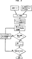
図3は本発明により人工的ニューラルネットワークに対するトレーニング手順を示し、
図4は本発明に関連して適用可能なグラフィックユーザインターフェース構造を示し、
図5は本発明に関連して適用可能なグラフィックインターフェースビューを示す。
蒸気タービンの作動中ウィンデイジ(windage)に基づく加熱を作動モードにより許容可能な限界内に維持しなければならない。本発明によるHP及びLPタービンに対するウィンデージ(windage)モジュールは、オペレータに、それぞれのタービン段にて羽根温度の推定をさせるものである。ここで、開示されているインターラクティブユーザインターフェースは、モリエル(Mollier)線図ないしh-s線図内で実時間値、それらの値のトレンドグラフ及びそれぞれのステート状態をディスプレイ表示する。推奨されるべき監視検査情報が推定及び他のアクセス利用可能な測定値から引き出され得る。
風の影響、風の修整量ないし爆風を表わすウィンデイジ(windage)(本文中単にウィンデイジとも称する)に係わる現象の例について次に説明する。HPタービンではトリップ引き外しにつづいてタービンを通っての蒸気流がないのでエネルギ伝達の程度が、タービンにおける圧力及び蒸気密度に依存する。フルロードひき外し、トリップの際、相応の高いコールドの再熱器圧力が初期的に存在する。風損(windage loss)による許容されない加熱を回避するため、適当な圧力消滅又は所定の冷却蒸気流が要求される。モリエル(Mollier)線図における膨張線ラインは、フルロードが除かれてからゼロロードへの充分なHPタービン流の利点を指示する。オペレータは、そのような図形により遙かに一層良好な情報が得られる。
膨張/圧縮線のオンライン視覚化が、殊にタービンの他の部分−該部分は当該の所定の事例ではウィンデイジ(windage)現象に基づき過熱を受ける−にとって有用である。制御弁が例えば2つの低い方のヒータに対するクロスオーバーラインにおいて、閉じられるとき蒸気タービンを加熱するにはLPタービンは、最終段におけるウィンデイジ(windage)により惹起される温度上昇を許容限界内に保持すべく蒸気を冷却することを要求する。当該の作動モードにて、LPタービンにおける蒸気は、風損−これは最終段内で支配的に生じる−に基因、由来するエネルギを吸収する。
一般にウィンデイジ(windage)モジュールは、DIGESTシステムとして知られているシステムにて使用されたシステムアーキテクチャに従う。DIGESTは、ドイツ連邦共和国の企業体(a corporation of Germany)シーメンス社Siemens Aktiengesellschaft(Simens AG)のKWU−FTP−アクティビティ活動(KWU−FTP activity of Siemens Aktiengesellschaft)により開発されたパワーシステムプラントに対するモジュラ式監視システムである。DIGESTは、6つの異なるレベルに分割され得る1つのモジュラシステムアーキテクチャーこれについては以下簡略説明する−により特徴づけられる。モジュールコンポーネントは任意の選択的構造の構築において多分のフレキシビリティをもったものがCに記載されている。
提案されたウィンデイジ(windage)モジュールシステムアーキテクチャが図1に示してある。最初の2つのレベルが既にDIGESTの部分としてアクセス利用可能である。モディフィケーション修正変更は、管理的及びデータレベルに対してなされた。通信及びデータの双方のレベルにおけるモディフィケーションは、データバスを介してモジュール特有のデータをリクエスト要求するために必要とされ、また、データサーバ及びデータベースを生成するため必要とされるパラメータスペシフィケーションを含む。主なウィンデイジ(windage)モジュール開発は、主にアクション及びプレゼンテーションレベルでなされる。
図1に示されているように、ウィンデイジ(windage)モジュールにおける6つのレベルは次の通りである;
1.アクイジションレベル:このレベルは、データアクイジションプロセスをマネージし、このデータアクイジションプロセスは、シーメンス タイプtype siemens Simatic 5・ の幾つかのprogrammable logic controllers(PlC)2プログラマブブルロジックコントローラ(PLC)2を含む。Simatic5におけるドキュメンテーションは、Siemens Industrial Automationから利用可能である。それの容量ケイバビリティcapabilitiesは、信号サンプリング、A/D変換、限定された計算、シーケンスプロセスアクションの実行、サイクルタイミング及び開いた通信機能を包含する。これは当該の関連でデータアクイジション装置デバイスとして使用され、ここで所定のレートで測定データをサンプルし、それをデジタル化し、データをイーサネットワークを介して非同期的に転送する。
2.通信レベル;このレベルは、基本的に通信サーバ6であり、この通信サーバは、ネットワークとDEC(Digital Equipment Corporation)、デジタルワークステーションマシン間の情報の転送をマネージする。通信問題タスクを処理する標準DECモジュールはOmni Server/DECnet PhaseVと称される。データ転送をマネージするDEC内のプロセスは、DEC−S5, 8, 及び S5−DEC 10により表わされたデータ転送をマネージする。DEC−S5は、管理レベルからS5への転送をマネージし、そして、S5−DECはS5から管理レベルへのデータ転送をマネージする。
管理レベル
コントロールの管理レベルは、適正フォーマットでリクエストを通信レベルへ伝搬する−このことは、テレグラム ディストリビュータ(telegram distributor) module 12によりなされる−ことにより、ウインデイジ(windage)プロセスコントロールからのデータリクエストをハンドリング処理する。前記レベルは亦、所定のフォーマットで入来データをマネージし、データの記憶のためプロセスコントロールへ送り返す。このことは、テレグラム レシーバ(telegram receiver) moduleによりなされる。他の機能は、バッファ容量(de−log)をマネージすること,16,セルフチェックプロセス(watchdog),18,及び割込中断目的のための幾つかのタイマ/クロック(タイム−コントロール),20を包含する。セルフチェックプロセスは、主に、システム内でのすべてのプロセスのステータスをチェックし、必要ならばシステムをリブート(reboot)するべきものである。
アクションレベル;
アクションレベルは、連続的バックグラウンドプロセス及び計算をマネージする。それらは、データリクエストの開始起動(RQTs送信)、入来データのマネージメント(RDTs)、データ記憶、すべての計算プロセス及び結果の記憶を包含する。当該レベルの一層詳細な説明を次のセクションにて行う。このレベルは、亦、計算結果の妥当性をテストするアウトプットマネージメントを含み得る。このスキームにおいて、ハイブリッド人工的ニューラルネットワーク(ANN)推定器の結果が、常に、分析モジュールの結果と比較される。当該妥当性検証は、可能性のある悪い結果−これは通常、ANNトレーニング期間中、提示されたすべてのサンプルから遠く離れている入力値により惹起される−を検出するために要求される。大きな偏差があれば、さらなるリトレーニング(re-training)が正常であることが指示される。
5.データレベル
データレベルは、データ記憶及びアクセスに関するすべてのプロセスを処理する。これは、データサーバ22及びデータベース24を含む。データベースに対するすべてのアクセスは、データサーバ22を介してなされなければならない。データは一旦適正なフォーマットでデータベース24内に記憶されると、すべてのレベルで容易にアクセスされ得る。
6.プリゼンテーションレベル
プリゼンテーションレペルは、ユーザが、すべての必要な情報を、幾つかの異なる要領作法で、ビュー監視し、即ち、現行値、トレンドダイヤグラム及びモリエル(Mollier)線図をビュー監視し得るようにするGUIを与えるものである。前記プリゼンテーションレベルは、ウインデイジGUIインターフェースに必要とされる中間パラメータ値を記憶するための共用メモリ30から成る。フリーグラフィックスは、データベース内に記憶された任意のパラメータ値をプロットするための独立のグラフィックツールである。このツールは、オリジナルDIGESTシステムの部分として開発される。
情報は主要ウインデイジスクリーン(windage screen)でスタートする幾つかの層で提示される。後続の層は、各タービンセクションに対する詳細条件を示す。それらの層は、タービン作動に関する適正な判定をするためオペレータにとって重要なすべてのパラメータ値に関しての情報を与える。当該のレベル内でのプロセスに関するさらなる詳細は次のセクションにて与えられる。開発スクリーンは、幾つかの内部モジュール及びシステムパラメータ又はプロセスをアクセスするため設けられる;然し乍ら、主に、セキュリティ、安全保全上の理由の故に、当該の特性的事項、フィーチャは、実際の作動バージョンでは有利に省かれ得る。
監視プロセスは、必ずしも常に同じレートにてサイクル動作する必要はない;それは、タービン作動条件に依存すべきものである。幾つかのシナリオをそれぞれの特定のタービンに対して予め設定できる。例えば、無負荷、フルロード全負荷、スロー停止(slow shutdown)の際の低負荷、スタートアップ及び負荷除去。監視サイクルは、クリティカルな事情に応じて異なる条件に対して、自動的に調節されるべきであり、そして、それぞれのディスプレイを、オペレータをアシスト援助するようにポップアップするように配置構成し得る。
ウインデイジモジュールは基本的に2つの主要プロセス、バックグランドプロセス及びインタラクティブディスプレイプロセスを有する。バックグランドプロセスは、所要のパラメータ値を得ることに対して、所定レート羽根温度を計算することに対して、及び関連情報を適当な共用メモリ及びデータベース内にて記憶することに対して責務がある。インタラクティブディスプレイプロセスは、任意の時点でグラフィックに必要な又は要求された情報を示す。プロセスレートはすべての測定が安定化する前に、最小の所要時間だけ制限され、そして、タービン条件の厳しさに基づき変化する。クリティカルな羽根温度の近くでの作動は、一層速いプロセスレートを必要とし得る。
監視プロセス前に、ANNはトレーニングされねばならない。トレーニングサブ構造は、監視モジュールにて使用される適当なウエイト及びパラメータを生じさせることに対して責務がある。当該のプロセスはオフラインでなされ、GUIインターフェースを介して可制御でない。ネットワークは、予期された通常の作動領域に対して分析手段を使用して、推定された温度を計算することにより得られたシミュレートデータを使用してトレーニングされ、そして、実際のデータがフィールド実験で得られる。実験は、特定の低い蒸気流条件、例えば、停止(shutdown)、負荷のロス、及びスタートアップのような当該の条件にてデータを生成することに集中する。この配置構成は、全体的なタービン作動領域に対して羽根温度を推定し得るべきものである。推定器に対する最小入力は、主蒸気の圧力の測定値、主蒸気の温度、第3段の圧力及び排気圧力である。付加的な入力は、任意に設定され、評価され得る。
バックグランウンドプロセスは、測定データを取得し、羽根温度及び他の必要な値を計算し、適当な位置個所でそれらの値を記憶する。プロセスシーケンスは次のようなものである:
通信レベル(DEC−S5プロトコルを用いて)を介して及び管理レベル(テレグラムディストリビュータ)を介して、アクイジションレベルに対する所要の測定データに対するリクエスト要求すること。
データアクイジションシステムSimatic5(Siemens PLC)からの測定データを受信すること。リクエスト要求は、イーサネットワークを介して伝搬され、S5−DECプロトコルを用いて通信され、管理レベル内のテレーキャプチャ(tele−capture)によりマネージされる。測定パラメータのリストは、下記を包含する:
Pms=主蒸気の圧力(bar)
Tms=主蒸気の温度(°C)
P1= ブレーディング(blading;羽根植付)前の蒸気圧(bar)
T1= ブレーディング(blading;羽根植付)前の温度(°C)
P3= 第3段での圧力
Pex=再熱器後の排気圧(bar)
Peh=再熱器前の排気圧(bar)
Tch=再熱器前の排気温度(°C)
Tcb=底部ケーシング温度(°C)
Tcu=上部ケーシング温度(°C)
Tci=内部ケーシング温度(°C)
Tco=外部ケーシング温度(°C)
N= 回転速度(RPM)
Pout=出口パワー(MW)
入力データを所望のフォーマットにプリプロセスすること(インタープリタ)。このプロセスは、基本的に入力データストリングを読出し、これを標準ASCIIフォーマットにリフォーマットする。
更なるプロセシングのため中間ファイル内にデータを記憶すること。
推定器は測定値を用いて羽根温度を計算する。少なくともHPタービンに対して、羽根温度を推定するため用いられる入力測定値は次の通りである:
主蒸気の圧力(Pms),
主蒸気の温度(Tms),
第3段における圧力(P3rd),及び
排気圧力(Pex)・
回転速度
1つのアプローチはストレートな3層ANN、図2Aを用いて羽根温度を直接的に推定する。第2のアプローチは中間パラメータの分解により、ハイブリッド技術図2Bを使用する、但し;
a.1つの中間パラメータ(T3)が下記方程式の関係式1を用いて分析的に計算される

b.他の中間定数(n)は、現行の入力値に基づくトレーニングされたANNにより計算される。
c.次いで2つの中間値を用いて現行の羽根温度が下記方程式の関係式2を用いて計算される。
次いで羽根温度推定及び他の測定パラメータは2つの異なった場所で記憶される:データベース及び中間共用メモリ
a.すべての値がデータサーバを介してデータベース中に記憶される。
b.GUI内でのディスプレイに必要とされる値は、亦一時的共用メモリ内に記憶される。
次いでそれらの値は、GUI プロセスにより読取できるようにしてアクセス利用可能である。
図3は、直接的アプローチ、又はハイブリッドアプローチにおいてANNモジュールに適用可能な一般的トレーニングプロセスを示す。唯一の差異は、バックグランウンドプロセスにおいて指示されているような入力パラメータである、当該のプロセスをは、次のように記述できる:
第1のステップは、水/蒸気サイクル分析及び実験から得られたデータを用いてシミュレートから得られた各データを結合する。そのような分析は、例えばDIGESTシステム内での熱力学系内に含まれている。水/蒸気サイクル分析はDIGESTシステムにおける熱力学系内に使用されている。前述のようにDIGEST監視システムは、SIEMENS AGの市販品として現在利用可能である。
次いでデータはリフォーマットされ、而して、ANNの入力フォーマットに適合せしめられる。次いで、データは、データを2つの別個のデータファイルに分けることにより再構成され、ここで、1つは、トレーニング及び検証目的のため使用され、もう1つはテスト目的のため使用される。利用可能なデータをリグルーピングするための所定のルールは存在しないけれども、データは、すべての作動領域が良好に表されるように再構成されるべきである。本発明の実施形態によれば、利用可能データの80%がトレーニング及び妥当性検証のため利用され、そして、残りがテストのため利用される。
ANN構造は1つの隠れレイヤを有する標準マルチレイヤである。隠れユニットの数は、4〜10であり、パフォーマンス性能の点で大した改善は得られない;比較的長いトレーニング期間が、比較的多数の隠れユニットに対して必要とされ、オーバーフィティング過適合のリスクがある。
図3に参照して言及すれば、最適化アルゴリズム、起動励振関数のタイプ、隠れユニットの数、エラー限界値を含めたトレーニングパラメータの初期のセットからスタートして、トレーニングプロスがスタートされる。使用された最適化アルゴリズムは、種々の最適化又はニューラルネットワークテキストブック中でアクセス利用可能な標準技術である。下記文献を参照のこと。
例えば Hertz, A. Krogh,and R.G.Palmer、“Introduction to the theory of neural computation”、A lecture notes volume in the Santa Fe Institute Studies in the Sciences of Complexity、Addison−Wesley Publishing Company、July 1991; and D.Rumelhart, J.L. McClelland、and the PDP Research Group、 “Parallel distributed processing: Exploration in the mocrostusture of cognition、 Volume 1:Foundations”、 MIT press、 Cambridge 1987.
幾つかの技術を勾配降下法、及び僅かの共役的勾配技術を含めて、本発明に関連して調べた。
妥当性検証限界値が満足されるようにシステムが収束すれば、ANNパラメータ(コネクションウエイト及びユニットの限界値)はテストのため記憶される。システムが収束しないならば、トレーニングパラメータは、解が得られるまでモデファイしなければならない。
前述のプロセスは繰り返してなされ得る、それというのはシステムが、異なる初期条件及びトレーニングパラメータを以て、異なる解に収束し得ることが一般に知られているからである。相当な数の解を得ることはグローバルな最適解を見出す可能性を増大させ得る。
次いで各解は、データテストファイルを用いてテストされる。最小のエラーを有する解が、バックグランウンドプロセス1中推定プロセスにて使用される。
現在の値及びトレンドダイヤグラムのほかに、GUIも亦蒸気挙動特性−モリエ線図内でタービン条件を示すことができるのである。モリエル線図とも称される当該のダイヤグラム、エントロピー/エンタルピー線図又はトータルの熱/エントロピーダイヤグラムは、任意の熱力学関係エンジニアにとってのなじみのある環境として、また、すべての既知のクリティカルな作動境界条件に関しての一層良好な表現として用いられる。従って、当該のオンラインタービン条件視覚化は適当なコントロールアクションをとる上でユーザに役立つものである。
一般的にGUIプロセスはユーザにより開始起動させねばならない。これは必要に応じてバックグランウンドプロセスにより記憶される値をアクセスする。GUIプロセスは次のようなステップに従う(図4中の相応の図解)。
ウインデイジ(windage)GUIモジュールを独立的に、又はDIGEST内から開始起動され得る。このことにより共用メモリユニットへのコネクションが開始起動される。共用メモリユニットは、基本的に次のようなルーチンである、即ち、GUIと、その外部にある任意のプロセス−これは主にバッファを含む−との間のデータの転送及びアクセスをマネージするルーチンである。
フロントページ、図5Aから、ユーザはタービンメニューを介して選択セレクトでき、下記のタービンウインドウのうちの任意のものをビューできる:
−HP タービン
−LP1 タービン
−LP2 タービン、又は
−任意の他のタービン(適用可能なもののうち)
各タービンに対して、3つのビューウインドウがあり、それらの3つのビューウインドウは、“ダイヤグラム”メニューを介して選択セレクトできる:
−タービンオーバービューウインドウ(図5(b)−5(d))
−モリエル線図(図5(e)−5(g))、又は
−トレンドダイヤグラムウインドウ(図5(h)−5(j)).
“タービンオーバービューウインドウ”は、羽根温度の現在値及び他の情報−これはタービンのコントロールに関してユーザが任意の判定をする上で重要なものであり得る−を与えるものである。
モリエル線図は前述の著書のような任意の熱力学テキストブックにてアクセス利用、知得可能な、標準的熱力学計算に基づいて生成される。ここでルーチンが使用され、このルーチンは、バックグランウンドモリエルグリッド(background Mollier grid)を生成し、次いで、膨張データ−これはグリッドのトップ上部における現行の測定値から計算される−を重畳する。例えば、そのようなルーチンは、Siemens AG社のVISUM,a user manual、 Version 3, October 1992. から利用可能である。
モリエル線図ウインドウ内に構築された幾つかのフィーチャ特性的事項は下記の内容を含む:
1.マウスにより所望の領域を囲んでボックスをリクエストすることにより、エンタルピー/エントロピーグラフ内でズームし得ること.
2.インスタント瞬時のミニトレンドダイヤグラム。これは、相応のパラメータ値テーブル/ボックスのところをクリックすることにより起動され得る。
3.モリエルオプションインターフェースは、ユーザの任意選択的なビューパラメータを個人化する手法手段を提供するものである。このことにより、亦、温度限界値設定がなされ得、この温度限界値設定によっては、ユーザが、警告ウオーミングラベルを起動して、アラーム信号をオペレータに送るための所定の限界値の調整セッティングをなし得るようにするものである。
トレンドダイヤグラムは、同時に示されるべき10までのパラメータの選択を可能にする。示し得るパラメータの最大数は実質上限られていない;然しながら、10より大の任意の数はグラフ自体をビューする上で困難性を生じさせる。それはモリエル線図におけるフィーチャ#2と同じフィーチャ、特性的事項を有する。グラフ内での精確な値を、所望のポイント上でのクリックにより見出し得る、精確な値は相応の軸のもとでディスプレイされる。
トレンドダイヤグラムウインドウから、ユーザは、さらに“FREE GRAPHICS”をセレクトすることによりデータを分析でき、前記の“FREE GRAPHICS”は、完全なデータベースに対してのユーザアクセスを与えるものである。このコンポーネントは、DIGESTシステム内に設けられる。
GUIディスプレイプロセスは、“FREE GRAPHICS”ルーチンを除いて共用メモリから必要なデータをアクセスするものであり、前記“FREE GRAPHICS”はデータサーバを介してデータベースからのデータにアクセスするものである。
本発明は幾つかの実施例について説明してきたが種々の変更、モディフィケーションが本発明の技術水準に通暁する当業者にとって可能である。例えば、ここでなされるパラメータの選択は、選択又は設計上の事項として変更し得るものである。それらの、そして類似の変更は請求の範囲の構成要件により規定される本発明の精神を逸脱することなく範囲内に入るものである。During operation of a steam turbine, such as in a turbogenerator, it is important that the operating parameters be kept within predetermined limits for proper and safe operation, including the start-up and shutdown phases. Unstable operation can have a serious impact on personal injury.
Referenced here is the name A GRAPHICAL USER INTERFACE SYSTEM FOR STEAM TURBINE OPERATING CONDITIONS--filed simultaneously by the inventor--the disclosure of which is made to the extent that it does not conflict with the present invention.
Typically in a steam turbine-generator, the turbine is operated at near full power or shut down if the power demand is insufficient. In particular, as part of a large power grid, it may be required to be able to operate with less than full load during operation. Under such conditions, temperature, pressure, steam wetness, reheat, expansion, and compression can result in excessive turbine blade temperatures. Such conditions can lead to blade failure, possibly resulting in a disastrous catastrophic consequence. It is practically important to monitor operation under conditions where the intake steam pressure is below the outlet pressure. The following books are available as background literature:
W. W Bathie, “Fundamentals of gas turbines”, John Wiley and Sons, 1996; Herlock, “Axial flow turbines: Fluid mechanicals and thermal dynamics”, Butterworth, London, 1960.
A good mathematical model for simulating steam behavior characteristics in a turbine in its overall operating range is not readily available, especially where the main-steam pressure is close to the exhaust pressure. Or is not readily available for lower periods. During such periods, the fluid flow flow behavior characteristics are significantly more complex because the radial component of velocity is significant compared to the axial component of velocity. The simplified mathematical model available for simulating steam behavior characteristics during normal load operation does not work properly when the intake pressure is near or lower than the outlet pressure.
In a new large steam turbine, a temperature measuring device is installed in each stage of the HP and LP casings. Depending on these measurements, instructions are given to the assigned supervisory inspection engineer or operator whenever the blade temperature exceeds its limit. In addition to the need for temperature monitoring for relatively small and older turbines, the need for a more practical and cost effective approach than temperature probe installations has led to the following demands and needs: Estimating turbine blade temperature in real time and monitoring turbine blade temperature during operation—recognized here—is creating a need and need.
The invention should advantageously be implemented using a programmable computer.
According to one aspect of the present invention, a method for estimating blade temperature in a steam turbine includes measurement parameters including pressure and temperature at locations other than just next to the blade, primarily at the inlet and outlet stages. Use. Initially, blade temperature is simulated by using a water / steam cycle analysis program and by directed, directed experiments. The artificial neural network (ANN) is trained by giving the measurement value and the blade temperature value to the artificial neural network (ANN). According to one embodiment of the present invention, four values give one satisfactory result. In one method development, ANN is used to derive the operating blade temperature value directly.
According to the hybrid approach of another aspect of the present invention, the artificial neural network is trained by providing the artificial neural network with the measured value and the blade temperature value. In the hybrid approach, five measurements are used. For example, one subset of four parameter values is used for ANN training, and for example, another subset of three values is used to perform calculations on other intermediate parameters. . Using the intermediate parameters and one of the five measurements, the blade temperature is calculated.
According to yet another aspect of the invention, the user interface provides a real-time information display for the monitoring engineer responsible for turbine operation, so that unfavorable combinations of critical parameter values and operating conditions can be easily observed. The deviation is clearly indicated, and as a result, the correction operation can be started quickly. Although a graphical plot of the parameters can be easily presented, such a format is generally used for the overall turbine state with respect to temperature distribution and coupling, combination, pressure, steam wetness or superheat and turbulence turbulence effects. The target image is not given easily.
In accordance with the present invention, an operational overview can be more easily demonstrated as follows: a line on the chart of Mollier's enthalpy / entropy indicates the expansion and compression operation process during operation This makes it easier to specify. In combination, real-time parameter values and parameter trends are also presented. Using the Mollier diagram in conjunction with trend and real-time information, inspection engineers can more quickly identify and correct inconvenient, potentially disturbing operating conditions.
According to one aspect of the present invention, a hybrid ANN (artificial neural network) -algorithm-based scheme is used here to estimate blade temperature from other commonly available measurements. Measurements are used. Training data for ANN includes both mathematical models and experimentally generated data.
The invention will be better understood from the following description with reference to the figures.
FIG. 1 shows a module architecture for a windage according to the present invention,
FIG. 2 shows an artificial neural network for blade temperature estimation according to the present invention,
FIG. 3 shows a training procedure for an artificial neural network according to the present invention,
FIG. 4 shows a graphic user interface structure applicable in connection with the present invention,
FIG. 5 shows a graphical interface view applicable in connection with the present invention.
During operation of the steam turbine, windage-based heating must be maintained within limits acceptable by the mode of operation. The windage module for HP and LP turbines according to the present invention allows the operator to estimate the blade temperature at each turbine stage. Here, the disclosed interactive user interface displays real-time values, trend graphs of those values, and respective state states in a Mollier diagram or an hs diagram. Surveillance test information to be recommended can be derived from estimates and other accessible available measurements.
An example of a phenomenon relating to windage (windage) representing the influence of wind, the amount of wind modification or blast (also referred to simply as windage in the text) will be described below. Since the HP turbine has no steam flow through the turbine following trip trip, the degree of energy transfer depends on the pressure and steam density in the turbine. During full load trips and trips, a correspondingly high cold reheater pressure initially exists. In order to avoid unacceptable heating due to windage loss, proper pressure extinction or a predetermined cooling steam flow is required. The expansion line in the Mollier diagram indicates the benefits of sufficient HP turbine flow to zero load after full load is removed. The operator can obtain much better information with such graphics.
On-line visualization of the expansion / compression line is particularly useful for other parts of the turbine, which in the given case are subject to overheating due to the windage phenomenon. To heat the steam turbine when the control valve is closed, for example in the crossover line for the two lower heaters, the LP turbine keeps the temperature rise caused by the windage in the last stage within acceptable limits. It is necessary to cool the steam as much as possible. In this mode of operation, the steam in the LP turbine absorbs energy derived from windage damage, which occurs predominantly in the last stage.
In general, the windage module follows the system architecture used in a system known as the DIGEST system. DIGEST is a KWU-FTP activity of Siemens AG system developed by the Siemens Aktiengesellschaft (Siemens AG) of a corporation of Germany in the federal republic of Germany. System. DIGEST is characterized by a modular system architecture that can be divided into six different levels, which will be briefly described below. Module components are described in C with a lot of flexibility in building arbitrary optional structures.
A proposed windage module system architecture is shown in FIG. The first two levels are already accessible as part of DIGEST. Modification modification changes were made to administrative and data levels. Modifications at both the communication and data levels are required to request module specific data over the data bus, and parameter specifications are required to create data servers and databases. including. The main windage module development is done mainly at the action and presentation level.
As shown in FIG. 1, the six levels in the windage module are as follows:
1. Acquisition level: This level manages the data acquisition process, which includes several programmable logic controllers (PLC) 2 programmable logic controllers (PLC) 2 of the Siemens type
2. Communication level: This level is basically the communication server 6, which manages the transfer of information between the network, DEC (Digital Equipment Corporation), and digital workstation machines. The standard DEC module for handling communication problem tasks is referred to as Omni Server / DECnet Phase V. The process in the DEC that manages the data transfer manages the data transfer represented by DEC-S5, 8, and S5-DEC10. DEC-S5 manages the transfer from the management level to S5, and S5-DEC manages the data transfer from S5 to the management level.
Management level
The management level of the control propagates the request to the communication level in the proper format-this is done by the telegram distributor module 12-handling the data request from the windage process control . The level will soon manage incoming data in a predetermined format and send it back to process control for data storage. This is done by a telegram receiver module. Other functions include managing buffer capacity (de-log), 16, self-check process (watchdog), 18, and some timer / clock (time-control), 20 for interrupt interruption purposes. Include. The self-check process should mainly check the status of all processes in the system and reboot the system if necessary.
Action level;
The action level manages continuous background processes and computations. They include start initiation of data requests (RQTs transmission), management of incoming data (RDTs), data storage, all computational processes and result storage. A more detailed explanation of this level is given in the next section. This level can include output management to test the validity of the calculation results. In this scheme, the result of the hybrid artificial neural network (ANN) estimator is always compared with the result of the analysis module. The validation is required to detect possible bad results—this is usually caused by input values far from all presented samples during the ANN training period. A large deviation indicates that further re-training is normal.
5). Data level
The data level handles all processes related to data storage and access. This includes a data server 22 and a database 24. All access to the database must be made through the data server 22. Once stored in the database 24 in the proper format, the data can be easily accessed at all levels.
6). Presentation level
The presentation lepel is a GUI that allows the user to view and monitor all necessary information in several different ways, ie, view current values, trend diagrams and Mollier diagrams. Is to give. The presentation level comprises a shared memory 30 for storing intermediate parameter values required for the windage GUI interface. Free graphics is an independent graphics tool for plotting arbitrary parameter values stored in a database. This tool is developed as part of the original DIGEST system.
Information is presented in several layers starting with the main windage screen. Subsequent layers show detailed conditions for each turbine section. These layers provide information on all parameter values that are important to the operator in order to make proper decisions regarding turbine operation. More details on the process within that level are given in the next section. Development screens are provided to access several internal modules and system parameters or processes; however, mainly due to security and security reasons, the characteristics, features are not May be advantageously omitted.
The monitoring process need not always cycle at the same rate; it should depend on the turbine operating conditions. Several scenarios can be preset for each particular turbine. For example, no load, full load full load, low load during slow shutdown, start-up and load removal. The monitoring cycle should be adjusted automatically for different conditions depending on the critical situation, and each display can be arranged to pop up to assist the operator.
A windage module basically has two main processes, a background process and an interactive display process. The background process is responsible for obtaining the required parameter values, for calculating the predetermined rate blade temperature, and for storing the relevant information in the appropriate shared memory and database. . The interactive display process shows the information required or required for the graphic at any point in time. The process rate is limited by a minimum duration before all measurements are stabilized and varies based on the severity of the turbine conditions. Operation near the critical blade temperature may require a faster process rate.
Prior to the monitoring process, the ANN must be trained. The training substructure is responsible for generating appropriate weights and parameters for use in the monitoring module. The process is done offline and is not controllable via the GUI interface. The network is trained using simulated data obtained by calculating the estimated temperature, using analytical means for the expected normal operating area, and the actual data is field experiment It is obtained with. Experiments concentrate on generating data at specific low vapor flow conditions, such as shutdown, load loss, and such conditions as startup. This arrangement should be able to estimate blade temperature for the overall turbine operating region. The minimum inputs to the estimator are main steam pressure measurements, main steam temperature, third stage pressure and exhaust pressure. Additional inputs can be arbitrarily set and evaluated.
The background process acquires measurement data, calculates blade temperature and other required values, and stores these values at the appropriate locations. The process sequence is as follows:
Request a request for the required measurement data for the acquisition level via the communication level (using the DEC-S5 protocol) and via the management level (telegram distributor).
Receiving measurement data from the data acquisition system Simmatic5 (Siemens PLC); The request request is propagated through the Ethernet network, communicated using the S5-DEC protocol, and managed by tele-capture within the management level. The list of measurement parameters includes:
Pms = Main steam pressure (bar)
Tms = Main steam temperature (° C)
P1 = Vapor pressure (bar) before blading
T1 = temperature (° C) before blading
P3 = pressure in the third stage
Pex = Exhaust pressure after reheater (bar)
Peh = Exhaust pressure before reheater (bar)
Tch = exhaust temperature before reheater (° C)
Tcb = Bottom casing temperature (° C)
Tcu = Upper casing temperature (° C)
Tci = inner casing temperature (° C)
Tco = outer casing temperature (° C)
N = Rotational speed (RPM)
Pout = Outlet power (MW)
Pre-processing input data into a desired format (interpreter). This process basically reads the input data string and reformats it into the standard ASCII format.
Store data in an intermediate file for further processing.
The estimator calculates the blade temperature using the measured value. At least for the HP turbine, the input measurements used to estimate the blade temperature are as follows:
Main steam pressure (Pms),
Main steam temperature (Tms),
The pressure in the third stage (P3rd), and
Exhaust pressure (Pex)
Rotational speed
One approach uses a straight three-layer ANN, FIG. 2A, to directly estimate the blade temperature. The second approach uses hybrid technology Figure 2B, with intermediate parameter decomposition, however;
a. One intermediate parameter (T3) is analytically calculated using
b. The other intermediate constant (n) is calculated by the trained ANN based on the current input value.
c. Then, using the two intermediate values, the current blade temperature is calculated using relation 2 of the following equation:
The blade temperature estimate and other measurement parameters are then stored in two different locations: database and intermediate shared memory
a. All values are stored in the database via the data server.
b. The values required for display within the GUI are stored in temporary shared memory.
Those values are then available for access by the GUI process.
FIG. 3 shows a general training process that can be applied to the ANN module in a direct or hybrid approach. The only difference is the input parameters as indicated in the background process, which can be described as follows:
The first step combines each data obtained from the simulation using data obtained from water / steam cycle analysis and experiments. Such an analysis is contained in a thermodynamic system, for example in the DIGEST system. Water / steam cycle analysis is used in the thermodynamic system in the DIGEST system. As mentioned above, the DIGEST monitoring system is currently available as a commercial product of SIEMENS AG.
The data is then reformatted and thus adapted to the ANN input format. The data is then reconstructed by dividing the data into two separate data files, where one is used for training and validation purposes and the other is used for testing purposes. Although there are no predetermined rules for regrouping the available data, the data should be reconstructed so that all working areas are well represented. According to embodiments of the invention, 80% of the available data is used for training and validation, and the rest is used for testing.
The ANN structure is a standard multi-layer with one hidden layer. The number of hidden units is 4-10 and does not give much improvement in terms of performance performance; a relatively long training period is required for a relatively large number of hidden units and overfitting overfitting There are risks.
Referring to FIG. 3, the training process is started, starting from an initial set of training parameters including optimization algorithm, type of activation excitation function, number of hidden units, error limits. The optimization algorithm used is a standard technique accessible in various optimization or neural network textbooks. See the following document.
For example, Hertz, A.M. Krogh, and R.K. G. Palmer, “Introduction to the theory of neurocomputation”, A note notes volume in the Santa Fe Institute in Wyeth in the Sciences in the Sciences of the United States. Rumelhart, J.A. L. McClelland, and the PDP Research Group, “Parallel distributed processing: Exploration in the structure of cognition, Volume 1: Foundations ss.
Several techniques were investigated in connection with the present invention, including gradient descent and a few conjugate gradient techniques.
If the system converges so that the validation limits are met, the ANN parameters (connection weights and unit limits) are stored for testing. If the system does not converge, the training parameters must be modified until a solution is obtained.
The above process can be done iteratively because it is generally known that the system can converge to different solutions with different initial conditions and training parameters. Obtaining a significant number of solutions can increase the likelihood of finding a global optimal solution.
Each solution is then tested using a data test file. The solution with the smallest error is used in the estimation process during
In addition to current values and trend diagrams, the GUI can also indicate turbine conditions in the soot steam behavior characteristics-Mollier diagram. The relevant diagram, also known as the Mollier diagram, the entropy / enthalpy diagram or the total thermal / entropy diagram is a familiar environment for any thermodynamic engineer and all known critical operating boundary conditions Is used as a better expression for. Therefore, such on-line turbine condition visualization helps the user in taking appropriate control actions.
Generally, the GUI process must be started and activated by the user. This accesses the value stored by the background process as needed. The GUI process follows the following steps (corresponding illustration in FIG. 4):
The windage GUI module can be started independently or from within DIGEST. As a result, the connection to the shared memory unit is started and activated. A shared memory unit is basically a routine that manages the transfer and access of data between the GUI and any process outside it, including mainly buffers. It is.
From the front page, FIG. 5A, the user can select and select through the turbine menu and view any of the following turbine windows:
-HP turbine
-LP1 turbine
-LP2 turbine, or
-Any other turbine (among those applicable)
There are three view windows for each turbine, and these three view windows can be selected and selected via the “Diagram” menu:
-Turbine overview window (Figs. 5 (b) -5 (d))
-Mollier diagram (Fig. 5 (e) -5 (g)), or
-Trend diagram window (FIGS. 5 (h) -5 (j)).
The “turbine overview window” provides the current value of the blade temperature and other information—which may be important for the user to make any decisions regarding control of the turbine.
The Mollier diagram is generated based on standard thermodynamic calculations that can be accessed and learned in any thermodynamic textbook such as the aforementioned book. Here a routine is used, which generates a background Mollier grid and then superimposes the dilation data—which is calculated from the current measurements at the top top of the grid. For example, such routines are described in Siemens AG, VISUM, a user manual, Version 3, October 1992. Is available from
Some feature features built in the Mollier diagram window include:
1. Be able to zoom in the enthalpy / entropy graph by requesting a box around the desired area with the mouse.
2. Instant instant mini-trend diagram. This can be triggered by clicking on the corresponding parameter value table / box.
3. The Mollier option interface provides a means of personalizing the user's optional view parameters. As a result, a temperature limit value can be set. Depending on the temperature limit value setting, the user can activate the warning warming label and set the predetermined limit value to send an alarm signal to the operator. It is what you get.
The trend diagram allows the selection of up to 10 parameters to be shown simultaneously. The maximum number of parameters that can be shown is not substantially capped; however, any number greater than 10 creates difficulties in viewing the graph itself. It has the same features and characteristics as feature # 2 in the Mollier diagram. The exact value in the graph can be found by clicking on the desired point, and the exact value is displayed under the corresponding axis.
From the trend diagram window, the user can further analyze the data by selecting “FREE GRAPHICS”, which gives the user access to the complete database. This component is provided in the DIGEST system.
The GUI display process is for accessing necessary data from the shared memory except for the “FREE GRAPHICS” routine, and the “FREE GRAPHICS” is for accessing data from a database via a data server.
While the present invention has been described with respect to several embodiments, various modifications and modifications will occur to those skilled in the art who are familiar with the level of the present invention. For example, the selection of parameters made here can be changed as a matter of choice or design. These and similar modifications are within the scope without departing from the spirit of the invention as defined by the appended claims.
Claims (5)
水/蒸気サイクル分析プログラムを使用することにより、及び指向された、方向づけられた実験により羽根温度値をシミュレートすること;
人工ニューラルネットワーク(ANN)に前記測定値及び前記羽根温度値を与えることにより、前記人工ニューラルネットワーク(ANN)をトレーニングすること;
実時間測定値を前記ANNに供給することを特徴とする蒸気タービンにおける羽根温度推定方法。A method for estimating blade temperature in a steam turbine using measured parameter values including pressure and temperature at at least one of the inlet and outlet stages comprises the following steps:
Simulating blade temperature values by using a water / steam cycle analysis program and by directed, directed experiments;
Training the artificial neural network (ANN) by providing the artificial neural network (ANN) with the measured value and the blade temperature value;
A blade temperature estimation method in a steam turbine, characterized in that real-time measurements are supplied to the ANN.
前記パラメータ値の第1のサブセットを生成すること;
前記の第1のサブセットを、前記ANNをトレーニングするため利用すること;
前記パラメータ値の第2サブセットを生成すること;
中間パラメータを導出するための計算を実施するため、前記の第2のサブセットを利用すること;
前記の中間パラメータ及び前記の測定パラメータ値のうちの1つを利用して、羽根温度値を計算することを特徴とする請求の範囲3記載の方法。It has the following steps:
Generating a first subset of the parameter values;
Utilizing the first subset to train the ANN;
Generating a second subset of the parameter values;
Utilizing said second subset to perform calculations to derive intermediate parameters;
4. The method of claim 3, wherein the blade temperature value is calculated using one of the intermediate parameter and the measured parameter value.
Applications Claiming Priority (3)
| Application Number | Priority Date | Filing Date | Title |
|---|---|---|---|
| US08/764,381 US5832421A (en) | 1996-12-13 | 1996-12-13 | Method for blade temperature estimation in a steam turbine |
| US08/764,381 | 1996-12-13 | ||
| PCT/US1997/022159 WO1998026336A1 (en) | 1996-12-13 | 1997-12-05 | A method for blade temperature estimation in a steam turbine |
Publications (2)
| Publication Number | Publication Date |
|---|---|
| JP2002501584A JP2002501584A (en) | 2002-01-15 |
| JP4005143B2 true JP4005143B2 (en) | 2007-11-07 |
Family
ID=25070566
Family Applications (1)
| Application Number | Title | Priority Date | Filing Date |
|---|---|---|---|
| JP52680798A Expired - Fee Related JP4005143B2 (en) | 1996-12-13 | 1997-12-05 | Blade temperature estimation method in steam turbine |
Country Status (12)
| Country | Link |
|---|---|
| US (1) | US5832421A (en) |
| EP (1) | EP0944866B1 (en) |
| JP (1) | JP4005143B2 (en) |
| KR (1) | KR100523382B1 (en) |
| CN (1) | CN1105950C (en) |
| AT (1) | ATE205310T1 (en) |
| CZ (1) | CZ300956B6 (en) |
| DE (1) | DE69706563T2 (en) |
| ES (1) | ES2167023T3 (en) |
| PL (1) | PL185983B1 (en) |
| RU (1) | RU2213997C2 (en) |
| WO (1) | WO1998026336A1 (en) |
Families Citing this family (22)
| Publication number | Priority date | Publication date | Assignee | Title |
|---|---|---|---|---|
| US7690840B2 (en) | 1999-12-22 | 2010-04-06 | Siemens Energy, Inc. | Method and apparatus for measuring on-line failure of turbine thermal barrier coatings |
| US7035834B2 (en) * | 2002-05-15 | 2006-04-25 | Caterpillar Inc. | Engine control system using a cascaded neural network |
| US20040082069A1 (en) * | 2002-10-25 | 2004-04-29 | Liang Jiang | Systems and methods for estimating exposure temperatures and remaining operational life of high temperature components |
| CN1298458C (en) * | 2003-09-29 | 2007-02-07 | 宝山钢铁股份有限公司 | Method for real-time estimating temperature of liquid steel in RH fining furnace |
| CN100338447C (en) * | 2004-07-24 | 2007-09-19 | 桂林电子工业学院 | Method for measuring temp. in high-temp. high-pressure closed cavity |
| US7021126B1 (en) | 2004-09-15 | 2006-04-04 | General Electric Company | Methods for low-cost estimation of steam turbine performance |
| FR2876152B1 (en) * | 2004-10-06 | 2006-12-15 | Renault Sas | IMPROVED METHOD AND SYSTEM FOR ESTIMATING EXHAUST GAS TEMPERATURE AND INTERNAL COMBUSTION ENGINE EQUIPPED WITH SUCH A SYSTEM |
| US7654734B2 (en) | 2005-05-10 | 2010-02-02 | General Electric Company | Methods and devices for evaluating the thermal exposure of a metal article |
| US8065022B2 (en) * | 2005-09-06 | 2011-11-22 | General Electric Company | Methods and systems for neural network modeling of turbine components |
| US7432505B2 (en) * | 2006-05-04 | 2008-10-07 | Siemens Power Generation, Inc. | Infrared-based method and apparatus for online detection of cracks in steam turbine components |
| US20100298996A1 (en) * | 2007-10-16 | 2010-11-25 | Gadinger Joerg | Method for operating a power station |
| US8478473B2 (en) * | 2008-07-28 | 2013-07-02 | General Electric Company | Method and systems for controlling gas turbine engine temperature |
| JP5804668B2 (en) * | 2009-06-10 | 2015-11-04 | 三菱重工業株式会社 | In-plane compressive strength evaluation apparatus and method |
| US8813498B2 (en) | 2010-06-18 | 2014-08-26 | General Electric Company | Turbine inlet condition controlled organic rankine cycle |
| CN102541025B (en) * | 2012-01-29 | 2014-04-09 | 上海锅炉厂有限公司 | Real-time control algorithm of International Association for Properties of Water and Steam (IAPWS)-IF 97 based on thermal properties of water and steam |
| US8903753B2 (en) * | 2012-02-06 | 2014-12-02 | General Electric Company | Steam turbine performance testing |
| JP6092723B2 (en) | 2013-06-25 | 2017-03-08 | 三菱日立パワーシステムズ株式会社 | Start-up control device for steam turbine plant |
| US10954824B2 (en) | 2016-12-19 | 2021-03-23 | General Electric Company | Systems and methods for controlling drum levels using flow |
| US10677102B2 (en) * | 2017-02-07 | 2020-06-09 | General Electric Company | Systems and methods for controlling machinery stress via temperature trajectory |
| RU2686385C1 (en) * | 2018-05-23 | 2019-04-25 | федеральное государственное автономное образовательное учреждение высшего образования "Санкт-Петербургский национальный исследовательский университет информационных технологий, механики и оптики" (Университет ИТМО) | Method of spectrometric determination of gas flow temperature |
| GB201908496D0 (en) | 2019-06-13 | 2019-07-31 | Rolls Royce Plc | Computer-implemented methods for determining compressor operability |
| GB201908494D0 (en) | 2019-06-13 | 2019-07-31 | Rolls Royce Plc | Computer-implemented methods for training a machine learning algorithm |
Family Cites Families (21)
| Publication number | Priority date | Publication date | Assignee | Title |
|---|---|---|---|---|
| US4025765A (en) * | 1972-04-26 | 1977-05-24 | Westinghouse Electric Corporation | System and method for operating a steam turbine with improved control information display |
| US3873817A (en) * | 1972-05-03 | 1975-03-25 | Westinghouse Electric Corp | On-line monitoring of steam turbine performance |
| US4227093A (en) * | 1973-08-24 | 1980-10-07 | Westinghouse Electric Corp. | Systems and method for organizing computer programs for operating a steam turbine with digital computer control |
| JPS6024283B2 (en) * | 1978-08-31 | 1985-06-12 | 株式会社東芝 | Steam turbine internal abnormality diagnosis device |
| US4891948A (en) * | 1983-12-19 | 1990-01-09 | General Electric Company | Steam turbine-generator thermal performance monitor |
| JPS60201008A (en) * | 1984-03-26 | 1985-10-11 | Hitachi Ltd | Method and apparatus for controlling operation of plant |
| US4764025A (en) * | 1985-08-08 | 1988-08-16 | Rosemount Inc. | Turbine blade temperature detecting pyrometer |
| US4679399A (en) * | 1985-09-13 | 1987-07-14 | Elliott Turbomachinery Co., Inc. | Protection system for steam turbines including a superheat monitor |
| US4827429A (en) * | 1987-06-16 | 1989-05-02 | Westinghouse Electric Corp. | Turbine impulse chamber temperature determination method and apparatus |
| US4970670A (en) * | 1988-11-30 | 1990-11-13 | Westinghouse Electric Corp. | Temperature compensated eddy current sensor temperature measurement in turbine blade shroud monitor |
| JP2907858B2 (en) * | 1989-03-20 | 1999-06-21 | 株式会社日立製作所 | Display device and method |
| JPH0692914B2 (en) * | 1989-04-14 | 1994-11-16 | 株式会社日立製作所 | Equipment / facility condition diagnosis system |
| JP2656637B2 (en) * | 1989-11-22 | 1997-09-24 | 株式会社日立製作所 | Process control system and power plant process control system |
| JPH04131600A (en) * | 1990-09-19 | 1992-05-06 | Hitachi Ltd | City energy system |
| US5353628A (en) * | 1991-07-26 | 1994-10-11 | Westinghouse Electric Corporation | Steam purity monitor |
| US5640176A (en) * | 1992-01-24 | 1997-06-17 | Compaq Computer Corporation | User interface for easily setting computer speaker volume and power conservation levels |
| EP0553675A1 (en) * | 1992-01-29 | 1993-08-04 | Siemens Aktiengesellschaft | Method and device for control of the temperature of a turbine component |
| US5267435A (en) * | 1992-08-18 | 1993-12-07 | General Electric Company | Thrust droop compensation method and system |
| US5386689A (en) * | 1992-10-13 | 1995-02-07 | Noises Off, Inc. | Active gas turbine (jet) engine noise suppression |
| US5311562A (en) * | 1992-12-01 | 1994-05-10 | Westinghouse Electric Corp. | Plant maintenance with predictive diagnostics |
| US5439160A (en) * | 1993-03-31 | 1995-08-08 | Siemens Corporate Research, Inc. | Method and apparatus for obtaining reflow oven settings for soldering a PCB |
-
1996
- 1996-12-13 US US08/764,381 patent/US5832421A/en not_active Expired - Lifetime
-
1997
- 1997-12-05 PL PL97333952A patent/PL185983B1/en unknown
- 1997-12-05 CN CN97180635A patent/CN1105950C/en not_active Expired - Fee Related
- 1997-12-05 WO PCT/US1997/022159 patent/WO1998026336A1/en active IP Right Grant
- 1997-12-05 AT AT97951539T patent/ATE205310T1/en active
- 1997-12-05 JP JP52680798A patent/JP4005143B2/en not_active Expired - Fee Related
- 1997-12-05 ES ES97951539T patent/ES2167023T3/en not_active Expired - Lifetime
- 1997-12-05 CZ CZ0212099A patent/CZ300956B6/en not_active IP Right Cessation
- 1997-12-05 KR KR10-1999-7005120A patent/KR100523382B1/en not_active IP Right Cessation
- 1997-12-05 DE DE69706563T patent/DE69706563T2/en not_active Expired - Lifetime
- 1997-12-05 RU RU99115461/09A patent/RU2213997C2/en not_active IP Right Cessation
- 1997-12-05 EP EP97951539A patent/EP0944866B1/en not_active Expired - Lifetime
Also Published As
| Publication number | Publication date |
|---|---|
| RU2213997C2 (en) | 2003-10-10 |
| KR100523382B1 (en) | 2005-10-24 |
| DE69706563D1 (en) | 2001-10-11 |
| KR20000057472A (en) | 2000-09-15 |
| PL333952A1 (en) | 2000-01-31 |
| EP0944866A1 (en) | 1999-09-29 |
| PL185983B1 (en) | 2003-09-30 |
| JP2002501584A (en) | 2002-01-15 |
| CN1240521A (en) | 2000-01-05 |
| WO1998026336A1 (en) | 1998-06-18 |
| CN1105950C (en) | 2003-04-16 |
| ES2167023T3 (en) | 2002-05-01 |
| EP0944866B1 (en) | 2001-09-05 |
| CZ300956B6 (en) | 2009-09-23 |
| DE69706563T2 (en) | 2002-07-11 |
| ATE205310T1 (en) | 2001-09-15 |
| US5832421A (en) | 1998-11-03 |
| CZ212099A3 (en) | 2000-03-15 |
Similar Documents
| Publication | Publication Date | Title |
|---|---|---|
| JP4005143B2 (en) | Blade temperature estimation method in steam turbine | |
| EP0944768B1 (en) | A graphical user interface system for steam turbine operating conditions | |
| US5249260A (en) | Data input system | |
| Rossi et al. | Gas turbine combined cycle start-up and stress evaluation: A simplified dynamic approach | |
| KR20030057442A (en) | Method and apparatus for assessing performance of combined cycle power-plants | |
| US20120323530A1 (en) | Virtual sensor systems and methods for estimation of steam turbine sectional efficiencies | |
| Nannarone et al. | Start-up optimization of a CCGT power station using model-based gas turbine control | |
| US20130263651A1 (en) | Detection and classification of failures of power generating equipment during transient conditions | |
| Bahlawan et al. | Development of reliable narx models of gas turbine cold, warm, and hot start-up | |
| Lindsay | A display to support knowledge based behavior | |
| Mehrpanahi et al. | Semi-simplified black-box dynamic modeling of an industrial gas turbine based on real performance characteristics | |
| Seifi et al. | An intelligent tutoring system for a power plant simulator | |
| JP2003193808A (en) | Diagnostic method and diagnostic system of electric power plant | |
| JP2002364311A (en) | Supporting system for dynamic behavior analysis of thermal electric power plant | |
| US20230288891A1 (en) | Operational optimization of industrial steam and power utility systems | |
| EP4254092A1 (en) | Information processing apparatus, information output method, and information output program | |
| Leppänen | Improving Steam Turbine Performance with Industrial Internet | |
| Leithner et al. | Monitoring | |
| Odena et al. | Multi-Method Fault Detection of Cooling Fan in Control Cabinet using Temperature Analysis | |
| JPH0573885B2 (en) | ||
| Surgenor | Thermal performance analysis: an expert systems approach | |
| Barszcz et al. | Application of an open environment for simulation of power plant unit operation under steady and transient conditions | |
| JPS6394004A (en) | Starting device for power generation plant | |
| Deverno et al. | Canadian CANDU plant data systems for technical surveillance and analysis | |
| Doran et al. | Applying THERMAC to Recover Lost Megawatts at Power Plants |
Legal Events
| Date | Code | Title | Description |
|---|---|---|---|
| A621 | Written request for application examination |
Free format text: JAPANESE INTERMEDIATE CODE: A621 Effective date: 20041203 |
|
| TRDD | Decision of grant or rejection written | ||
| A01 | Written decision to grant a patent or to grant a registration (utility model) |
Free format text: JAPANESE INTERMEDIATE CODE: A01 Effective date: 20070807 |
|
| A61 | First payment of annual fees (during grant procedure) |
Free format text: JAPANESE INTERMEDIATE CODE: A61 Effective date: 20070823 |
|
| R150 | Certificate of patent or registration of utility model |
Free format text: JAPANESE INTERMEDIATE CODE: R150 |
|
| FPAY | Renewal fee payment (event date is renewal date of database) |
Free format text: PAYMENT UNTIL: 20100831 Year of fee payment: 3 |
|
| FPAY | Renewal fee payment (event date is renewal date of database) |
Free format text: PAYMENT UNTIL: 20100831 Year of fee payment: 3 |
|
| FPAY | Renewal fee payment (event date is renewal date of database) |
Free format text: PAYMENT UNTIL: 20110831 Year of fee payment: 4 |
|
| FPAY | Renewal fee payment (event date is renewal date of database) |
Free format text: PAYMENT UNTIL: 20110831 Year of fee payment: 4 |
|
| S111 | Request for change of ownership or part of ownership |
Free format text: JAPANESE INTERMEDIATE CODE: R313111 |
|
| FPAY | Renewal fee payment (event date is renewal date of database) |
Free format text: PAYMENT UNTIL: 20110831 Year of fee payment: 4 |
|
| R350 | Written notification of registration of transfer |
Free format text: JAPANESE INTERMEDIATE CODE: R350 |
|
| FPAY | Renewal fee payment (event date is renewal date of database) |
Free format text: PAYMENT UNTIL: 20110831 Year of fee payment: 4 |
|
| FPAY | Renewal fee payment (event date is renewal date of database) |
Free format text: PAYMENT UNTIL: 20120831 Year of fee payment: 5 |
|
| FPAY | Renewal fee payment (event date is renewal date of database) |
Free format text: PAYMENT UNTIL: 20120831 Year of fee payment: 5 |
|
| FPAY | Renewal fee payment (event date is renewal date of database) |
Free format text: PAYMENT UNTIL: 20130831 Year of fee payment: 6 |
|
| R250 | Receipt of annual fees |
Free format text: JAPANESE INTERMEDIATE CODE: R250 |
|
| LAPS | Cancellation because of no payment of annual fees |