JP4003000B2 - Video signal recording / reproducing method, video signal recording / reproducing apparatus, and video signal recording / reproducing program - Google Patents
Video signal recording / reproducing method, video signal recording / reproducing apparatus, and video signal recording / reproducing program Download PDFInfo
- Publication number
- JP4003000B2 JP4003000B2 JP2002145776A JP2002145776A JP4003000B2 JP 4003000 B2 JP4003000 B2 JP 4003000B2 JP 2002145776 A JP2002145776 A JP 2002145776A JP 2002145776 A JP2002145776 A JP 2002145776A JP 4003000 B2 JP4003000 B2 JP 4003000B2
- Authority
- JP
- Japan
- Prior art keywords
- video signal
- signal
- recording
- time
- recorded
- Prior art date
- Legal status (The legal status is an assumption and is not a legal conclusion. Google has not performed a legal analysis and makes no representation as to the accuracy of the status listed.)
- Expired - Lifetime
Links
Images


Classifications
-
- H—ELECTRICITY
- H04—ELECTRIC COMMUNICATION TECHNIQUE
- H04N—PICTORIAL COMMUNICATION, e.g. TELEVISION
- H04N5/00—Details of television systems
- H04N5/76—Television signal recording
- H04N5/78—Television signal recording using magnetic recording
- H04N5/782—Television signal recording using magnetic recording on tape
- H04N5/783—Adaptations for reproducing at a rate different from the recording rate
-
- H—ELECTRICITY
- H04—ELECTRIC COMMUNICATION TECHNIQUE
- H04N—PICTORIAL COMMUNICATION, e.g. TELEVISION
- H04N21/00—Selective content distribution, e.g. interactive television or video on demand [VOD]
- H04N21/40—Client devices specifically adapted for the reception of or interaction with content, e.g. set-top-box [STB]; Operations thereof
- H04N21/41—Structure of client; Structure of client peripherals
- H04N21/4104—Peripherals receiving signals from specially adapted client devices
- H04N21/4112—Peripherals receiving signals from specially adapted client devices having fewer capabilities than the client, e.g. thin client having less processing power or no tuning capabilities
-
- H—ELECTRICITY
- H04—ELECTRIC COMMUNICATION TECHNIQUE
- H04N—PICTORIAL COMMUNICATION, e.g. TELEVISION
- H04N21/00—Selective content distribution, e.g. interactive television or video on demand [VOD]
- H04N21/40—Client devices specifically adapted for the reception of or interaction with content, e.g. set-top-box [STB]; Operations thereof
- H04N21/47—End-user applications
- H04N21/488—Data services, e.g. news ticker
-
- H—ELECTRICITY
- H04—ELECTRIC COMMUNICATION TECHNIQUE
- H04N—PICTORIAL COMMUNICATION, e.g. TELEVISION
- H04N5/00—Details of television systems
- H04N5/76—Television signal recording
- H04N5/78—Television signal recording using magnetic recording
- H04N5/781—Television signal recording using magnetic recording on disks or drums
-
- H—ELECTRICITY
- H04—ELECTRIC COMMUNICATION TECHNIQUE
- H04N—PICTORIAL COMMUNICATION, e.g. TELEVISION
- H04N9/00—Details of colour television systems
- H04N9/79—Processing of colour television signals in connection with recording
- H04N9/80—Transformation of the television signal for recording, e.g. modulation, frequency changing; Inverse transformation for playback
- H04N9/804—Transformation of the television signal for recording, e.g. modulation, frequency changing; Inverse transformation for playback involving pulse code modulation of the colour picture signal components
- H04N9/8042—Transformation of the television signal for recording, e.g. modulation, frequency changing; Inverse transformation for playback involving pulse code modulation of the colour picture signal components involving data reduction
- H04N9/8045—Transformation of the television signal for recording, e.g. modulation, frequency changing; Inverse transformation for playback involving pulse code modulation of the colour picture signal components involving data reduction using predictive coding
Description
【0001】
【発明の属する技術分野】
本発明は、受信チャンネルを設定してTV放送の映像、及び音声信号を得てハードディスクなどの記録媒体に記録しながら、その記録中の映像信号を読み出すようにした同時記録再生を行う映像信号の記録再生方法、映像信号記録再生装置、及び映像信号記録再生用プログラムに関するものである。
【0002】
【従来の技術】
記録媒体としてハードディスクなどのランダムアクセス可能な情報信号記録媒体を用いた映像信号記録再生装置は、記録、再生のためのアクセス時間が短いなどの利点から、TV放送の複数の番組を同時に記録したり、放映中の映像信号の記録と再生を同時に行うなど、その利点を生かした便利な機能を有している。
【0003】
そして、この様な同時記録再生機能を有する映像信号記録再生装置は、放送中の番組を現在から過去に連続的にタイムシフトしながら視聴できるキャッシュ再生や過去に記録を開始した映像信号を、現在記録中の映像信号に追いつくようにして再生できる追っかけ再生などの便利な機能を有しており、従来のタイムシフトマシンとして利用されているVTRと共に多く市場に導入されていくものと予想されている。
【0004】
その従来のVTRにおける記録信号のモニタは、VTRに内蔵されるTVチューナの信号を直接モニタTVに供給して視聴するようになされており、そのモニタ映像は記録途中の映像信号のモニタはできるものの、実際にどのようにビデオテープに記録されているか、そしてその記録映像の画質劣化、又は何らかの原因により記録がなされない状態にあるかなど、何らかの異常がある場合でもそれを記録時に知ることはできていない。
【0005】
それに対し、同時記録再生機能を有する装置では、記録中の映像をリアルタイムで再生しながら記録を行えるため、記録時の不具合についてもその時点で知ることができ、記録ミスを最低限におさえた記録を行なうことができる。
【0006】
そして、上述したように記録中に再度見たい映像、または見逃してしまった映像があるときには、簡易な操作により過去の映像を見ることができるなど、ハードディスクを用いて行う記録再生の機能は視聴者にとって便利な機能であり、そのような機能を搭載したPVR(personal video recorder)の開発が進んでいる。
【0007】
【発明が解決しようとする課題】
ところで、視聴者においてそのような便利な機能を有する装置を使用する場合、従来のテレビ視聴で良くなされる視聴チャンネルを頻繁に切り替えながら複数の番組を同時視聴するような利用方法もあり、そのような場合ではハードディスクレコーダにも複数の番組が頻繁に切り替えられて記録されることになる。
【0008】
そのチャンネルの頻繁な切り替えは、番組を視聴中の視聴者の意志によりなされるもので、そのように複数の記録された番組を後日視聴するような場合、連続性のない細切れになされた番組の視聴に対して違和感を生じる。
【0009】
そして、その違和感は、単に番組の一部が欠けて記録されたものよりも、カテゴリの異なる番組が雑多に表示されるような場合の方がより不快に感じられる。また、ハードディスクレコーダは、キャッシュ再生、及び追っかけ再生などの便利な機能の他に、従来のVTRで行なわれていたタイムシフトマシンとしての利用に対しても十分な機能の提供を前提とするものでなければならない。
【0010】
そこで本発明は、そのような便利な機能を有する映像信号記録再生装置において、仮に記録中である映像信号の受信チャンネルが切り替えられてしまうような場合であっても、その受信チャンネルが切り替えられて記録される映像信号の乱れを少なくし、また違和感も少なく再生でき、さらにキャッシュ再生時にチャンネル切り替え動作がなされたときには操作者にキャッシュ再生中であることを認識させる等の機能達成するための映像信号の記録再生方法、映像信号記録再生装置、及び映像信号記録再生用プログラムを提供しようとするものである。
【0011】
【課題を解決するための手段】
本発明は、上記課題を解決するために、以下の1)〜4)の手段より成るものである。
すなわち、
【0012】
1) 外部より順次設定されて受信される受信チャンネルの映像信号を記録媒体に記録し、記録された映像信号のうち選択可能な受信チャンネルの映像信号を再生するに際し、設定された受信チャンネルに係る圧縮符号化された映像信号を時間軸圧縮してランダムアクセス可能な記録媒体への記録と、この記録された信号の再生とを交互に行ないつつ、再生信号の時間軸伸長と復号化とを行ってモニタ表示用信号を得る映像信号の記録再生方法において、
前記受信チャンネルの設定が変更されたときに受信チャンネルの変更信号を出力する第1のステップ(79、76)と、
前記変更信号の出力時に得られた映像信号の媒体への記録位置に係る第1の位置情報を得る第2のステップ(76)と、
前記受信チャンネル変更時点から所定時間の間に前記受信チャンネルの変更信号が検出される場合には新たに検出された時点を受信チャンネル変更時点とし、前記受信チャンネル変更時点から前記所定時間の間に前記受信チャンネルの変更信号が検出されない場合には直前に検出された受信チャンネル変更時点で得られる映像信号の媒体への記録位置に係る第2の位置情報を得る第3のステップ(76)と、
前記選択可能な受信チャンネルの映像信号の再生を、前記第1の位置情報と前記第2の位置情報とで指定される記録部分をスキップして行う第4のステップ(65、76)と、
を有することを特徴とする映像信号の記録再生方法。
2) 外部より順次設定されて受信される受信チャンネルの映像信号を記録媒体に記録し、記録された映像信号のうち選択可能な受信チャンネルの映像信号を再生するに際し、設定された受信チャンネルに係る圧縮符号化された映像信号を時間軸圧縮してランダムアクセス可能な記録媒体への記録と、この記録された信号の再生とを交互に行ないつつ、再生信号の時間軸伸長と復号化とを行ってモニタ表示用信号を得る映像信号の記録再生方法において、
前記設定される受信チャンネルが順次変更された場合、前記順次変更されて受信される複数の受信チャンネルの番組部分のうち、受信された時間間隔が所定の時間間隔に満たない受信チャンネルの番組部分をスキップして再生することを特徴とする映像信号の記録再生方法。
3) 外部より順次設定されて受信される受信チャンネルの映像信号を記録媒体に記録し、記録された映像信号のうち選択可能な受信チャンネルの映像信号を再生するに際し、設定された受信チャンネルに係る圧縮符号化された映像信号を時間軸圧縮してランダムアクセス可能な記録媒体への記録と、この記録された信号の再生とを交互に行ないつつ、再生信号の時間軸伸長と復号化とを行ってモニタ表示用信号を得る映像信号記録再生装置において、
前記受信チャンネルの設定が変更されたときに受信チャンネルの変更信号を出力するチャンネル変更検出手段(79、76)と、
前記変更信号の出力時に得られた映像信号の媒体への記録位置に係る第1の位置情報を得ると共に、前記受信チャンネル変更時点から所定時間の間に前記受信チャンネルの変更信号が検出される場合には新たに検出された時点を受信チャンネル変更時点とし、前記受信チャンネル変更時点から前記所定時間の間に前記受信チャンネルの変更信号が検出されない場合には直前に検出された受信チャンネル変更時点で得られる映像信号の媒体への記録位置に係る第2の位置情報を得る位置情報取得手段(76)と、
前記選択可能な受信チャンネルの映像信号の再生を、前記第1の位置情報と前記第2の位置情報とで指定される記録部分をスキップして行う読み出し制御手段(65、76)と、
を具備して構成することを特徴とする映像信号記録再生装置。
4) 外部より順次設定されて受信される受信チャンネルの映像信号を記録媒体に記録し、記録された映像信号のうち選択可能な受信チャンネルの映像信号を再生するに際し、設定された受信チャンネルに係る圧縮符号化された映像信号を時間軸圧縮してランダムアクセス可能な記録媒体への記録と、この記録された信号の再生とを交互に行ないつつ、再生信号の時間軸伸長と復号化とを行ってモニタ表示用信号を得る機能をコンピュータを実行させて行う映像信号記録再生装置用プログラムであって、
前記受信チャンネルの設定が変更されたときに受信チャンネルの変更信号を出力する第1のステップ(S11)と、
前記変更信号の出力時に得られた映像信号の媒体への記録位置に係る第1の位置情報を得る第2のステップ(S12)と、
前記受信チャンネル変更時点から所定時間の間に前記受信チャンネルの変更信号が検出される場合には新たに検出された時点を受信チャンネル変更時点とし、前記受信チャンネル変更時点から前記所定時間の間に前記受信チャンネルの変更信号が検出されない場合には直前に検出された受信チャンネル変更時点で得られる映像信号の媒体への記録位置に係る第2の位置情報を得る第3のステップ(S16)と、
前記選択可能な受信チャンネルの映像信号の再生を、前記第1の位置情報と前記第2の位置情報とで指定される記録部分をスキップして行う第4のステップ(S18)と、
を少なくとも有して前記装置を制御することを特徴とする映像信号記録再生用プログラム。
【0013】
【発明の実施の形態】
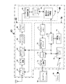
以下、本発明の映像信号の記録再生方法、映像信号記録再生装置、及び映像信号記録再生用プログラムの実施の形態につき、好ましい実施例により説明する。図1に、その映像信号の記録再生方法を採用した映像信号記録再生装置の概略ブロック図を示し、その構成と動作について概説する。
【0014】
同図において、この映像信号記録再生装置40は、記録部50、媒体部60、及び再生部70より成り、再生部70にはモニタTV90が接続されると共に、リモコン95が赤外線を介して送受信可能となっている。
【0015】
そして、記録部50は、TVチューナ51、A/D変換器52、MPEG−2エンコーダ53、ストリームアナライザ54、及びバッファメモリ55より構成されている。また、媒体部60はハードディスク記録再生器61、ハードディスク63、及び書き込み読み出し制御器65より構成されている。そして、再生部70はバッファメモリ71、MPEG−2デコーダ72、OSD(On Screen Display)73、D/A変換器74、マイコン76、一時記憶メモリ78、及びリモコンインタフェース79より構成されている。
【0016】
次に、それらの構成による動作について概説する。
まず、受信するTVチャンネルはリモコン95の操作により変調された赤外線信号が発光され、その赤外線信号がリモコンインタフェース79により受信され、その得られた受信チャンネル情報が記録部40内のTVチューナ51に供給される。
【0017】
TVチューナ51では、アンテナより入来する放送電波の内、選択された受信チャンネルの信号が受信され、得られたビデオ信号はA/D変換器52でディジタル信号に変換され、MPEG−2エンコーダ53に供給される。
【0018】
MPEG−2エンコーダ53では、供給された信号をISO/IEC(International Organization for Standardization / International Electrotechnical Commission)で定められたMPEG−2(moving picture experts group - 2)標準規格に従って圧縮符号化処理を行い、その処理した信号をストリームアナライザ54に供給する。
【0019】
ストリームアナライザ54では、圧縮符号化された信号の形式が解析され、その解析信号と共に圧縮符号化信号がバッファメモリ55に供給される。バッファメモリ55では記録(recording)用信号を一時記憶し、記録順にその信号をハードディスク記録再生器61へと出力する。
【0020】
そのハードディスク記録再生器61では、供給された信号をセクタサイズごとに分割し、その分割された信号を書き込み読出し制御器65の動作制御に基づきハードディスク63に供給し、ここで図示しない円盤状記録媒体に記録される。
【0021】
このようにして、チャンネル選択がなされて受信されたビデオ信号及び図示しない付随される音響信号は圧縮符号化された映像信号及び音響信号とされ、それらの信号はセクタサイズ毎に分割されてハードディスク63に記録されるようになされる。
【0022】
次に、上述のようにしてハードディスク63に記録された信号の再生について述べる。
まず、視聴者によりリモコン95の再生ボタンが操作された場合には、その操作内容は変調された赤外光線としてリモコンインタフェース79を介してマイコン76に供給される。
【0023】
そのマイコン76からは、操作内容に応じて生成された制御信号が書き込み読み出し制御器65に供給され、この制御信号に基づいてハードディスク63の指定された個所の信号が読み出され、その信号がハードディスク記録再生器61に供給される。
【0024】
ハードディスク記録再生器61では、その供給された信号の増幅及び周波数応答特性などの補正が行われ、その補正された信号がデコーダ部70のバッファメモリ71に供給される。バッファメモリ71では、その映像信号を一時記憶し、この一時記憶された信号はMPEG−2デコーダ72からの要求に応じてMPEG−2デコーダ72内に供給される。
【0025】
そのMPEG−2デコーダ72では、圧縮符号化された映像信号がMPEG−2標準に基づいて復号化され、得られたディジタルビデオ信号はOSD(On Screen Display)73を介してD/A変換器74に供給される。OSD73では、必要に応じてモニタTV90に表示される映像信号に多重して表示する例えばCH(チャンネル)表示信号も生成し、その表示信号を直接モニタTV90に供給したり、復号化された映像信号に多重された合成信号として、D/A変換器74を介してモニタTV90に供給される構成となっている。
【0026】
以上、アナログ地上放送の受信チャンネルを設定して受信される映像信号の圧縮符号化及び時間軸圧縮を行ってハードディスクに記録する。そして、記録した信号を再生して時間軸伸長と復号化とを行って表示用の映像信号を得るハードディスクレコーダの構成と動作について概説した。このときの記録と再生は時間軸圧縮された信号が高速ランダムアクセス可能なハードディスクに時分割された信号として記録と再生がなされるため、連続信号として供給される映像信号の記録及び再生の動作を同時に行うことが出来ている。
【0027】
そして、アナログ地上放送の場合では映像信号がアナログFM変調されて伝送されているため、圧縮符号化を行って媒体に記録するようにしているが、例えばMPEG−2方式により圧縮符号化のなされた映像信号として放送される際の記録では、A/D変換及びMPEG−2エンコードの信号処理を省くことができる。
【0028】
図2に、ディジタル放送を受信して記録及び再生を行う映像信号記録再生装置の構成を示す。
同図において、前述の図1に示した映像信号記録再生装置と同一機能のブロックには同一の符号を付し、その動作について説明する。
【0029】
まず、映像信号記録再生装置40aは衛星放送受信アンテナより供給される信号はBSチューナ51aで受信される。そこではリモコン95で選定された放送チャンネルの信号が受信され、MPEG−2により符号化された映像信号はミューティング回路58に供給される。
【0030】
そこでは、供給された映像信号をストリームアナライザ54に供給するが、正規の映像信号が供給されないときには、その信号の供給を停止する。例えばチャンネル変更の操作がなされ、BSチューナ51aより正常な映像信号が供給されないと想定される期間はその信号のストリームアナライザ54への供給を停止する。または、BSチューナ51aより供給される例えば同期捕捉完了信号、又は正常な復調動作を検出する信号が得られるまでの期間、ストリームアナライザ54への供給を停止するようにしてもよい。
【0031】
その停止に係る制御は、チャンネル変更操作情報がデコーダ部70のマイコン76により検出される。マイコン76からはBSチューナ51aより正常な映像信号が復調されるまでの期間に係る制御信号を生成し、その生成された制御信号をミューティング回路58に供給する。
【0032】
ストリームアナライザ54に供給された映像信号は、前述の映像信号記録再生装置40における動作と同様にして、ハードディスク63への映像信号の記録、及び記録信号の再生を同時に行うようにしている。
【0033】
以上、BSディジタル放送で放送される映像信号の記録及び再生について述べた。MPEG−2方式により符号化された信号の放送はBSディジタル放送の他にディジタル地上波放送でもなされる。そして、ディジタル地上波放送を受信する映像信号記録再生装置は図2に示したと同様の構成により実現できる。
【0034】
また一方、アナログCS(Communication Satellite)放送を受信して行う記録及び再生は、アナログCSチューナより供給されるアナログ映像信号を映像信号記録再生装置40の図示しないビデオ信号外部入力端子に入力する。そこに入力された信号はA/D変換器52に供給され、それ以降は前述と同様な動作がなされる。
【0035】
さらに、ディジタルCSチューナよりMPEG−2で符号化された映像信号の場合では、得られる符号化されたディジタル映像信号を、図示しない外部入力端子を介して映像信号記録再生装置40aのミューティング回路58に供給する。そして、デコーダ部70のリモコンインタフェース79では図示しないディジタルCSリモコンのチャンネル変更操作に係り発光される赤外光を検出して受信チャンネル情報を得るようにする。
【0036】
そこで検出された受信チャンネルの変更操作検出信号がマイコン76に供給されることにより、ディジタルCSチューナによる受信においても上述と同様な動作が行なわれる。
【0037】
以上、アナログ放送、及びディジタル放送を受信して行う記録及び再生の動作について述べた。そして、ハードディスクに対して行われる記録及び再生動作は、ディジタル映像信号がバッファメモリ55により時間軸圧縮され、ハードディスク記録再生器61によりセクタサイズ毎に分割されて、高速でハードディスクに記録される。
【0038】
そのセクタサイズ毎に分割されて記録された信号は再生され、セクタサイズ毎に分割された信号は結合されてバッファメモリ71に供給される。そこでは時間軸伸長され、MPEG−2デコーダ72により復号化されてアナログ映像信号が得られる。その時間軸圧縮及び時間軸伸長がなされることによりハードディスク上の離れた位置での記録及び再生が同時に行われる。
【0039】
その同時録再により、現在記録中の番組を記録しながら過去に記録した部分を再生するいわゆる後追い再生を行う。そして、所定の時間分のビットストリーム記録領域に順次映像及び音声情報を記録し、その領域の最後まで記録したときは、領域中の一番古い記録に対して新しい情報を上書きして記録しながら、所定時間分の映像音声情報を過去にさかのぼって再生することができるキャッシュ録再機能を実現している。
【0040】
そのキャッシュ録再により、通常は記録直後の再生映像をリアルタイム画像として視聴し、視聴者の操作によるリアルタイム映像から過去に記録した映像にタイムシフトしながらスムーズな再生映像を得ている。
【0041】
図3に、そのキャッシュ録再を行うときのビットストリームについて模式的に示す。
同図において、ハードディスク63に記録される映像信号のビットストリームの時間関係を示したもので、▲1▼はハードディスクより読み出したビットストリームを復号している時点であり、▲2▼は符号化されたビットストリームを記録している時点である。
【0042】
そして、▲1▼より左側に示される(1)は過去に遡って再生可能なビットストリームの部分を示し、▲2▼より右側の(3)は過去にビットストリームを記録した領域を示し、この部分に順次新しいビットストリームを記録する。
【0043】
▲1▼と▲2▼との間にある領域(2)は、例えばVBV(video buffering verifier)バッファとして動作するバッファメモリ71に所定量のビットストリームが一時記憶されてなく、MPEG−2デコーダにビットストリームを供給できなかったり、あるいは、デコーダが安定して映像、音声をデコードするのに必要なビットストリームの量が供給されてない等の理由により、安定した復号動作を行うために必要なビットストリーム量のデータが存在しない領域である。
【0044】
このようにして、ハードディスク63に記録される信号は、▲2▼で示される記録時点よりも所定時間経過後のビットストリーム領域(1)の期間でなければ再生ができず、その領域(1)の最も早い時間▲1▼を再生している状態をライブ状態と呼ぶことにする。
【0045】
次に、そのライブ状態で再生中に受信チャンネルの変更を行ったときに得られる映像のつながりについて述べる。
その受信チャンネルの変更がアナログテレビジョン放送に対しなされたときは、TVチューナ51の図示しないローカル発振器の発振周波数が変更されたチャンネルを受信するための周波数に変更され、変更されて入来する受信信号に図示しない映像信号復調回路の動作が同期状態となる。この時、供給される信号の動作レベルが自動調整されて復調動作が開始されるが、それらの回路動作は所定の遅延時間を伴いながら行われ、その間は正常な映像信号は得られない。
【0046】
また、一方、チャンネル変更が衛星テレビジョン放送の受信に対してなされるような場合では10GHzを超える局部発振出力の周波数安定度の確保に、またMPEG−2で圧縮符号化されて放送されるBSディジタル放送受信の場合ではI(Intra-coded)フレームが復号されるまでの間は正常な圧縮符号化信号の復号がなされない。また、例えば地上波ディジタル放送の受信に対しては、1000本を超えるキャリアが用いられるOFDM(Orthogonal Frequency Division Multiplexing)放送波への同期のために更なる動作時間が必要であるなど、チャンネル変更の操作がなされてから正常な映像信号が得られるまでには所定の時間が必要である。
【0047】
そのチャンネル変更の操作がなされてから正常な映像信号が得られるまでの間、正常でない映像信号をMPEG−2エンコーダで符号化してハードディスク63に記録して再生することは出来るが、キャッシュ再生時にそのような正常でない映像が表示されてしまうことは好ましくない。
【0048】
その正常でない映像が、視聴者によりチャンネル変更操作のなされたときに生じるのは、操作に伴って生じた映像であるとして視聴者に与える違和感は少ないが、過去の操作時の正常でない映像がキャッシュ再生時に突如として表示されるのは、視聴者に不快な印象を与えてしまうことになり、そのような映像は表示しないのが望ましい。
【0049】
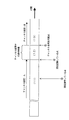
図4に、チャンネル変更時に表示される映像の状態を時間軸上で模式的に示す。
同図において、領域(11)は受信チャンネルAが受信され、領域(12)はチャンネル変更途中の乱れた映像が記録されている。そして領域(13)はチャンネル設定がBに変更され、正常なチャンネルBの映像信号が記録されている区間を示す。
【0050】
即ち、▲4▼はビットストリームを記録している現在時点であり、▲3▼はその▲4▼で記録された信号がハードディスクより読み出されて、バッファメモリ71に一時蓄積され、その後にMPEG−2デコーダで復号されて復号信号が得られる時点であり、その手前の▲5▼は変更されたチャンネルBの映像が正常に再生可能とされる時点である。
【0051】
次に、MPEG−2エンコーダ53のエンコード状態を操作してチャンネル変更途中の乱れた映像が表示されないようにする動作例を示す。
図5に、チャンネル変更時になされるエンコーダへの動作とハードディスクに記録される映像信号の時間関係について模式的に示す。
【0052】
同図において、受信チャンネルの設定がAとされると、領域(11)ではチャンネルAの圧縮符号化された映像信号が記録さる。そして、時点▲3▼において受信チャンネルがAからBに変更操作がなされるときは、その操作信号を基にMPEG−2エンコーダのエンコード動作を中止させ、その中止させた後の時点▲6▼において受信チャンネルの変更動作を開始するようにしてチャンネル変更時に生じる乱れた映像信号の符号化がなされないようにする。
【0053】
エンコードが中止された後もバッファメモリ55などに記憶されているチャンネルAの符号化信号が存在しているときは、ハードディスク63への記録が継続される。チャンネルAの符号化信号が存在しなくなる手前の時点▲7▼において映像信号の記録が中止されることにより領域(12)には信号は記録されなく、チャンネル変更途中の乱れた映像信号は再生されないことになる。
【0054】
その間、TVチューナ51では設定されたチャンネルBの正常な映像信号を得るべく同期動作等がなされている。そして、安定した映像信号の得られる時点▲8▼よりMPEG−2エンコーダ53のエンコード動作が再開される。
【0055】
そのエンコードの開始時点▲8▼は、TVチューナ51より同調の動作完了に係る信号を得てからエンコードを再開させることによりチャンネル変更途中の乱れた映像の符号化を防ぐことができる。また、仮に設定されたチャンネルが誤っており放送のなされていないチャンネルであったり、放送が終了されていて受信信号が得られないような場合には、その雑音信号の符号化を開始するような動作を防ぐことができる。
【0056】
そして、供給される映像信号が図示しない外部映像信号入力端子より供給されるような信号である場合は、その同期に係る信号を容易に得ることができないので、そのことを考慮して、例えば500ミリ秒を同期に係る所定時間とし、チャンネル切り替え操作後その所定時間の経過を待ってMPEG−2エンコーダのエンコードを開始させるようにしている。
【0057】
そして、MPEG−2エンコーダで変更されたチャンネルの圧縮符号化された映像信号の、Iフレームに係る符号化信号がハードディスク63に供給される時点9より記録が再開され、領域(13)にはチャンネルBに設定された信号が記録される。
【0058】
そして、このようにしてMPEG−2エンコーダの動作を一時停止さた後にエンコードを再開させるような場合では、記録される圧縮符号化信号(ビットストリーム)のタイムスタンプが不連続となってしまう。そして、タイムスタンプが不連続であるとする情報を符号化信号と共に記録しておくことにより、再生シーケンスの乱れを軽減することができる。
【0059】
しかし、MPEG−2デコーダの種類によって、その再生シーケンスの乱れとして一瞬映像がフリーズされるような場合もある。そのフリーズされる時点はプログラムソースが他のプログラムソースに変更されるときであるので、視聴上好ましくないとされるケースは少ない。
【0060】
以上のようにして、ハードディスク63に記録された映像信号にはチャンネル変更途中の乱れた映像信号が記録されることがないため、その記録された映像信号をキャッシュ再生により視聴するような場合であっても乱れた信号が再生されることはなくなる。
【0061】
そして、そのようなチャンネル変更に伴い生じる乱れた映像信号の処理は、MPEG−2エンコーダのエンコード動作を継続させたままエンコーダに供給される映像及び音声信号をミュート信号とする方法によっても良い。そして、その方法ではMPEG−2エンコーダに一時停止機能が装備されていないようなMPEG−2エンコーダに対して有効である。そのミュート用信号としては単色信号でも良く、また、複数のミュート色の信号が使用可能とされている。さらには、ミュート用信号を予め圧縮符号化した信号をメモリに蓄積しておき、ミュート時にその信号を読み出して用いるようにしても良い。
【0062】
図6に、そのミュート信号発生器によりミュート信号を発生させる場合の構成を示す。
同図に示す構成は、前述の図1に示した構成に対してA/D変換器52とMPEG−2エンコーダ53の間にマイコン76により制御される切り替えスイッチが接続されており、その切り替えスイッチによりA/D変換器52からの信号又はミュート信号発生器56で発生されるミュート信号のいずれかが切り替えられてMPEG−2エンコーダ53に供給されるようになされている。
【0063】
そして、スイッチの切り替えを行なうマイコン76は、リモコン95が操作されて生じるリモコンインタフェース79からの信号が供給された時点でミュート信号発生器56で発生される信号がMPEG−2エンコーダに供給されるようにスイッチが切り替えられる。そのスイッチ切り替えの後、例えば500m秒の所定の時間が経過したときに再びA/D変換器52からの信号がMPEG−2エンコーダ53に供給されるように再度スイッチの切り替えが行なわれる。
【0064】
このようなミュート処理により、MPEG−2エンコーダのエンコード動作を継続させたままでもチャンネル切り替え時の乱れた映像信号がキャッシュ再生のときに生じるのを防ぐことができる。
【0065】
なおここで、MPEG−2エンコーダに、上記と同様なミュート信号を発生させる機能が内蔵されているときは、マイコン76により直接MPEG−2エンコーダのミュート機能を制御することにより、MPEG−2エンコーダ53はTVチューナ51で生じるチャンネル切り替え時の正常でない映像信号の符号化を行なうことなく、その代わりに上記のようにミュート信号を符号化した信号をストリームアナライザ54に供給するようにしても良い。
【0066】
なお、上述の説明において、映像信号を中心とするミュート処理の説明を行ったが、音響信号に対するミュート処理も必要であり、そのときの処理は無音信号として処理される。
【0067】
このようにして、MPEG−2エンコーダに供給されるチャンネル切り替え時の正常でない信号をミュート信号に置換した信号として供給することができる。そして、MPEG−2エンコーダは正常でない映像信号のエンコード処理を行なうが、次にそのエンコードされた乱れた映像信号を出力信号としない場合の例について述べる。
【0068】
すなわち、この例としては、MPEG−2エンコーダはエンコードした圧縮符号化信号をハードディスク63に記録するに際し、セクター毎に分割された圧縮符号化信号とされ、それらの分割された符号化信号は媒体への記録位置アドレス、及びMPEG−2符号化画像のGOP(Group of Picture)の構造に係るIフレーム(ピクチャ)の記録位置情報などが管理情報により管理されて記録される場合である。
【0069】
その動作について前述の図1を用いて述べる。まず、MPEG−2エンコーダ53で圧縮符号化された信号はストリームアナライザ54、バッファメモリ55、及びハードディスク記録再生器61を介してハードディスク63に供給される。そのハードディスク63に記録される領域はマイコン76で生成されるディスク管理情報に基づいて書き込み読み出し制御器65が制御され、所定の記録領域に記録されるようになっている。
【0070】
そこで、リモコンインタフェース79により受信チャンネルの変更に係る操作信号が供給されたときは、受信チャンネルの変更に係るフラグ情報を、例えば500m秒の期間ディスク管理情報に書き込むようにし、キャッシュ再生はその管理情報を参照しつつ書き込み読み出し制御器65により制御されて、そのフラグの書き込まれている個所をスキップして再生を行う。
【0071】
当然のことながら、そのスキップするためのフラグの記録場所は、管理情報記録領域に行う外に圧縮符号化されたビットストリームのヘッダ領域に記録するようにし、そのヘッダに書かれるフラグ情報を参照しつつその個所のキャッシュ再生を停止、又はスキップ再生を行なうようにしても良い。また、そのフラグを一時記憶メモリ78に記憶する方法もある。
【0072】
そして、そのようなランダムアクセスが可能な記録媒体に記録された信号の再生スキップの手法は、記録されたCM(commercial message)部分をスキップして再生する技術が応用でき、その技術は本願発明者が発明し本願出願人により出願された特願2000−293739「映像信号記録装置、映像信号再生装置、及び映像信号記録再生装置」(本願出願時に未公開)に開示されている。
【0073】
また、同出願に開示されているCMスキップは、受信されるテレビジョン信号はそのままハードディスクなどの記録媒体に記録する。そして、記録された信号がCM信号として検出されるときはその部分がCM信号であることを管理情報領域にフラグを立てて「CM部である」ことを識別する。再生に際してはそのフラグ情報に基づいてCM部をスキップしたり、CM部を高速再生するようにしている。
【0074】
CMの場合には高速再生によりCM部の記録内容を短時間で再生でき、CM部を番組中の時間的なポインタ(目印)として利用できるなど便利な面がある。しかし、チャンネル切り替え時の場合にはそのような便利さはないので、その部分の高速再生は行なわず、その部分をスキップするようにする。
【0075】
そして、そのスキップ動作に伴い、表示される映像が瞬間的にフリーズされることもあるが、そのチャンネル切り替え時に生じるフリーズ再生画像はチャンネルが切り替えられたことにより生じるフリーズ画像であり、番組の連続性が中断されている個所でもあるので、視聴上の問題とはならない。
【0076】
このようにして、チャンネル切り替え時に生じる乱れた映像の表示をフラグにより管理し、その部分のキャッシュ再生を行わないようにする。そして、そのフラグにより識別される記録部分の映像信号は不要な映像信号であるため、その個所の映像を記録しないようしたり、また、記録後の空き時間に消去してしまう方法がある。
【0077】
その不要な映像信号部を記録しない方法としては、チャンネル切り替えにより過渡的に生じる乱れた映像であるとされる部分の圧縮符号化信号部分の記録は行わない。そして、そしてその信号部分に係る管理情報には「記録せず」とする管理情報を記録するものである。また、予め全ての信号を記録しておき、記録が終了した時点で、フラグ情報を基に不要とされる映像信号を消去してしまう方法によっても構わない。
【0078】
これらの方法を用いて、チャンネル切り替え時に生じる乱れた映像が表示されないようにできる。次に、そのチャンネル切り替えが続けて複数回行われるような場合における信号の処理方法について述べる。
【0079】
その複数回連続的に行われるチャンネル切り替えは、例えば視聴中のチャンネル4の番組に続いて、チャンネル6及び8が短時間ずつ視聴され、次のチャンネル10が長時間視聴されたような、チャンネルアップボタンが操作されて切り替えられるような場合である。
【0080】
図7に、そのようなチャンネル切り替えのなされた状態を模式的に示す。
同図において、(a)はリモコン95が操作されて、リモコンインタフェース79から供給される設定チャンネルの状態である。(b)はMPEG−2エンコーダ53及びバッファメモリ55などにより所定の遅延時間が与えられてハードディスク63に供給される信号をチャンネル番号と共に示したものである。(c)はハードディスク63から再生される映像信号を示したものである。
【0081】
そして、このようになされる複数チャンネルの短時間切り替え操作に対しては、途中のチャンネルを視聴する目的ではないと判断し、複数の連続的な操作を経て目的とする視聴チャンネルの切り替えがなされた場合であると判断する。例えば、1秒以内で順次切り替えられるような場合には、視聴目的ではないと判断する。
【0082】
キャッシュ再生の場合には、順次チャンネル切り替えされる前に記録された番組に遡って再生出来るが、このキャッシュ再生の場合には他の問題がある。
【0083】
その問題は、例えば10秒程度の短い時間のみ視聴されたチャンネルの映像も含めて遡って再生できる様にすると、短時間だけそのチャンネルの映像が再生されて次のチャンネルの映像が再生されることになる。その間、チャンネル切り替え動作による乱れた映像の再生はなされないものの、再生される番組の内容には連続性はないため、視聴者によっては不快に感じる場合もある。
【0084】
そこで、前述したように視聴時間が所定の時間に満たない例えば10秒以内のチャンネルの映像信号部分の再生は行わないようにする。即ち、10秒以内の記録信号には前述と同様のフラグ情報を、管理領域に記録し、そのフラグの記録された領域の圧縮符号化信号の再生を行わないようにする。あるいは、その部分の信号を消去するなどにより、過去に記録された、短時間の番組しか記録されなかったチャンネルの映像信号の再生をスキップするようにする。
【0085】
そのスキップ再生は、図7において(b)ハードディスク(HD)記録信号のch6及びch8の記録部分をスキップ期間とし、(c)ハードディスク再生信号としてはチャンネル4の信号に続いてチャンネル10の信号が再生されるようにする。
【0086】
そのようにして、視聴時間の短いチャンネルの再生をスキップした方が、視聴者の視聴希望が高い番組のみの再生を行うことができるため、このようにしてなされるキャッシュ再生は視聴者にとって快適であるとされるケースが多い。当然に、そのような動作はマイコン76に制御されて前述と同様にしてなされる。
【0087】
さらに、視聴者にとってキャッシュ再生の場合において、キャッシュ再生中のチャンネル情報やソース情報が示されれば、視聴者にとって極めて便利なものとなる。
【0088】
そのキャッシュ再生時のチャンネル情報は、管理情報として記憶しておき、そのチャンネル情報をOSD73により再生中の映像信号に多重して表示するようにする。
【0089】
通常のOSD機能は、例えば視聴チャンネルが切り替えられたときに切り替えられたチャンネルを表示し、所定時間経過後にその表示が中止され、切り替えられた映像番組のみが表示されるようになされている。
【0090】
キャッシュ再生動作中において、その再生中のチャンネル映像とは異なったチャンネル映像を再生するに至った場合には、その時点での異なったチャンネル映像のチャンネルを表示させるようにする。それにより異なるチャンネルの番組が再生されていることを視聴者に認識させる。
【0091】
そして、そのキャッシュ再生において、記録されている映像が外部入力端子を経て記録された映像であったり、入力ソースが不明でチャンネル情報のない映像を再生するに至った場合には、入力ソース等が不明であるとする識別表示、例えば「**」のような記号をその映像信号に多重して表示するようにする。
【0092】
そのようになされたキャッシュ再生のチャンネル表示は、今、例えば現在受信中のチャンネルが8チャンネルであり、現在より10分前に10チャンネルを、更にそれよりも5分前には8チャンネルを視聴し、現在ライブ状態で視聴しているとする。そのライブ状態で再生中の位置より10分間遡って再生されている間は8chと表示する。更に遡って再生される場合には10チャンネルの表示をするか、あるいは「**」の表示をする。
【0093】
図8に、キャッシュ再生時のチャンネル表示画面の例を示す。
同図において、記録と同じチャンネルの映像がキャッシュ再生されているときはその受信中の例えば10チャンネルのチャンネル番号10を示し、記録中と異なるチャンネルの映像がキャッシュ再生されているときはそのチャンネルが異なっていることを「**」のような記号を用いて示す。
【0094】
このようにして、例えば「**」のような数字でない識別記号を用いてチャンネル表示を行なうことによリ、キャッシュ録再により異なるチャンネルまで遡って再生中であることを忘れた視聴者が、チャンネルが替わっていなかったと誤解して誤ったチャンネル切り替え操作を行うような誤操作を防ぐことができるものである。
【0095】
このような、視聴者に対して誤操作をさせるような誤解を与えるのは、記録中のチャンネルとは異なる過去に視聴していたチャンネルまで遡ってキャッシュ再生を行っている時である。そのようなキャッシュ再生時にチャンネル切り替え操作がおこなわれようとしたときには、そのチャンネル操作が誤ってなされようとしたものであるか、あるいは正規になされようとしたものであるかを確認する必要がある。
【0096】
そこで、記録中と異なるチャンネルまで遡ってキャッシュ再生を行っているときにチャンネル切り替え操作がなされたときは、現在視聴中の映像をライブ状態の映像に変更して表示する。それにより、記録中のチャンネルに対してのチャンネル切り替え操作が行われたことを視聴者に知らせる。
【0097】
または、ライブ状態の映像に対してチャンネル変更が必要であるか否かの判断を求め、それに対する視聴者による操作を基にしてチャンネル変更を行うようにしても良い。
すなわち、1回のチャンネル変更操作でライブ状態にしてからチャンネル変更を行うか、又は1回目のチャンネル変更操作でライブ状態にして現在記録中の映像を表示し、2度目のチャンネル変更操作がされてはじめて操作されたチャンネルに変更するかのいずれかにより行うようにするものである。
【0098】
そして、1回の操作でチャンネル変更までなされたときに、視聴者が誤ったチャンネル変更であると認識した場合には、元のチャンネルに再変更を行うことになる。そして、その場合ではキャッシュ再生のための映像は一部欠落することになる。しかし、実用的には大きな問題とはならない。
【0099】
このようにして、遡った時間の位置でキャッシュ再生時にチャンネル変更操作がなされたときに、1度の操作で設定されたチャンネルの受信及び記録を行うか、あるいは1度の操作でライブ状態とし、2度目の操作で設定されたチャンネルの信号を受信するように動作させるかは、視聴者の操作性のニーズに応じて適宜選択される。
【0100】
このようにして、1つのキャッシュメモリに複数チャンネルの映像信号を記録して再生できるキャッシュ再生機能により、遡った時間の再生を行いながらチャンネル切り替え操作を行う場合は、再生状態を一旦記録直後の再生ライブ状態とすることによりチャンネル切り替えの操作ミスを軽減することができる。また、異なった番組を跨いでキャッシュ再生するに際しては、その異なった番組の再生であることをOSD機能により表示するようにするものである。
【0101】
そのチャンネル切り替えを跨いで再生される番組に多重して表示するOSDの機能は、チャンネル情報をチャンネル切り替え操作時に切り替え番組に対応した表示をしたり、あるいは、前の再生番組とは異なった番組を再生中であることを、数字ではない「**」などの識別表示で認識させるようにするものである。
【0102】
以上のようにして、複数の番組を記憶可能なキャッシュメモリを用いて、視聴者は複数放送される番組情報の時分割的な視聴を行えるものであり、且つ最も興味のある番組の内容を記憶しておき、その番組を好きな再生速度により繰り返して再生することも可能であるなど、放送される複数の番組に対して有効な視聴がなされる。
【0103】
次に、インデックスサーチ機能について説明する。
図9に、留守番録画と同様にしてキャッシュメモリにキャッシュ録画を行った場合の記録時間と記録チャンネルの関係を例示する。
同図におけるキャッシュ録画は、18:00より4chを、18:30から6chを、そして19:00から10chをのように行った場合である。
【0104】
このようにしてキャッシュ予約がなされてキャッシュ録画がなされた場合、そのチャンネルの録画開始位置にその録画開始の位置を示すポインタ情報を設定し、そのポインタ情報を基に番組のアクセスができるようにする。
【0105】
そのように予約して記録された番組の再生が、例えば19:20から開始されるような場合は、まず18:00よりの記録内容を再生し、視聴者の趣向に応じて18:30より記録された番組をポインタを用いて「インデックスサーチ」の再生を行なう。
【0106】
そのようなインデックスサーチ的な再生は、18:00から記録した番組を、時間表示を基に18:30から記録した番組まで早送り検索するよりも、リモコンキーを数回操作するのみで19:00、18:30、ないしは18:00から記録された番組を頭出しして再生が出来るなど、操作性が極めて良い。
【0107】
この例での映像信号記録装置では、ハードディスクに記録される圧縮符号化信号は、管理領域に受信チャンネル情報とハードディスクへの記録アドレスに係る情報が記録される。そして、その管理情報に基づいて再生がなされるため、その管理領域に記憶される受信チャンネル情報を基に再生を行なうことが可能であり、それに加えて前述したようなインデックスサーチの機能を併せ持たせることができるものである。
【0108】
以上、放送される信号を受信して、キャッシュ録再を行う映像信号の記録再生方法、及び映像信号記録再生装置の構成とその動作について述べた。そして、それらの動作はマイコン76に格納されるコンピュータプログラムにより実行されている。
【0109】
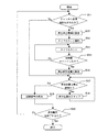
図10に、前述の図1に示した本実施例装置の動作に係るフローチャートを例示し、説明する。
このフローを実行させるプログラムは、例えばマイコン76に接続される一時記憶メモリ78に格納され、装置の制御動作を行う。
まず、S(ステップ)11において、リモコン95が操作されるとその操作情報はリモコンI/F79を介してマイコン76に供給され、そこでチャンネル変更操作が認識される。
【0110】
そして、S11においてチャンネル変更操作が認識されないときにはS17の動作に移る。また、チャンネルの変更操作が検出されたときには、S12においてチャンネル変更時点での検出信号がMPEG−2エンコーダに供給される。そこで、圧縮符号化のなされる映像信号には再生停止に係るフラグ信号が設定される。
【0111】
次に、S13においてマイコン76に内蔵されるタイマのカウントを開始する。そして、S14でのタイマのカウントは継続される。S15では、タイマのカウント数が所定のカウント数に達したかどうかが検出される。
【0112】
その所定数のカウントは、TVチューナ51からチャンネルが変更されて正常な映像信号が供給される時点までの期間に係るカウント数である。その数のカウントがなされたときにS16において、S12で設定された再生停止フラグの解除設定がなされる。
【0113】
そのフラグ情報の付される映像信号はハードディスク63に記録されて、再生される。その再生は、S17で再生停止フラグが検出されるときにはその再生場所をスキップし、再生停止フラグの設定されていない領域の記録信号がアクセスされて再生される。
【0114】
S19で、正常な映像信号が再生され、バッファメモリ71で時間軸伸長される。MPEG−2デコーダ72で復号化処理がなされて再生映像信号が得られる。その再生動作はS20において再生動作終了の操作がなされて一連の記録及び再生動作を終了する。
【0115】
以上、映像信号記録装置40に内蔵されるマイコン76を動作させるプログラムを基に実行される動作をフローチャートにより示し、その流れについて述べた。そして、そのプログラムは予め装置に組み入れられている場合、あるいは図示しないプロバイダの記憶装置に格納されているものがインターネットなどを介して装置に組み入れられる場合がある。そして、そのプログラムが用いられて実行される上記の動作は、ディジタル映像信号の供給される映像信号記録装置40aにおいても同様になされ、チャンネル切り替え時に生じる異常な映像信号を除いたキャッシュ録再がなされる。
【0116】
次に、キャッシュ記録されて再生される映像信号の遅延時間について述べる。その遅延時間は、記録及び再生のために映像信号の圧縮符号化、記録媒体への記録、再生、及び復号などの動作上必要な時間である。
【0117】
即ち、それらの動作は所定の時間を伴って行われるため、キャッシュ録再は遅延時間を伴って行われることになる。従って、例えば失敗の許されない記録の場合は多少の遅延時間よりは記録が確実に所定の品質でなされていることをリアルタイムでチェックしながら記録再生を行うこととなる。しかし、それほど厳重に行なう必要のない記録再生では、記録時には遅延時間の少ない信号を再生しつつ記録を行う方が望ましい。
【0118】
図11を用いて、記録済み信号やこれから記録を行なう信号に対するの3つの再生方法について示す。
同図において、符号a1〜a4で示される太い実線による信号の流れは、前記のハードディスクに記録した信号を再生するときの信号の流れである。
【0119】
そして、遅延時間の少ない再生方法としては、例えば点線でbとして示すようにMPEG−2エンコーダで圧縮符号化を行なった映像信号をMPEG−2デコーダ72に供給して復号化を行ない、その復号化された信号をモニタTV90に表示するようにして映像品質をモニタする方法がある。
【0120】
このような映像信号の圧縮符号化及び復号を行ないながら映像信号の記録を行う方法では、記録媒体に異常があるときにその検出を行うことはできないが、誤って記録信号の伝送レートを低く設定してしまったような場合で、圧縮符号化時に歪が生じてモニタされるため、その圧縮符号化による不具合を記録中に発見することができる。
【0121】
その圧縮符号化及び復号化を行なう場合においても遅延時間は生じており、さらに遅延時間の少ない映像信号のモニタを行なう必要がある場合もある。そのときには、点線でcとして示すように、A/D変換器52より供給される信号をOSD73に供給し、必要なチャンネル表示などのOSD機能と共に受信される映像信号をモニタTV90に表示する方法である。
【0122】
この場合は、受信される映像信号に遅延時間がほとんど生じないため、例えば供給される信号が図示しない外部端子より供給されるカメラ撮影映像信号をモニタTVによりモニタしながら、その映像信号にタイトル画を多重するといったような操作も適切に行なうことができる。
【0123】
そして、この遅延時間を伴わないモニタ表示によるTV放送の受信においても、チャンネルが変更されて得られる映像信号を即座に表示することができる。その方法は、レスポンスの良い受信チャンネル変更の操作、ないしは記録中の受信チャンネルが適性であるかどうかをスピーディにチェックすることができるなど好ましいものである。
【0124】
以上述べたようにして、モニタ表示すべき映像信号は、ディジタル信号に変換された直後の信号、圧縮符号化のなされた信号、媒体に記録する直前の信号、さらには媒体に記録した信号を再生した信号など、そのときに記録する映像信号の内容に応じて視聴者が希望する個所の信号を選択して表示出来るようにする。それにより、目的に合った映像信号のモニタリングを行なえ、好適である。
【0125】
このようにして、ランダムアクセス記録の出来る記録媒体を用いる映像信号記録装置における再生信号のモニタ方法には複数の方法があるが、その映像信号記録装置の構成にも複数の方法がある。即ち、映像信号記録装置40を、記録部50と媒体部60により構成される映像信号記録装置として、また再生部70を映像信号再生装置として構成する方法である。
【0126】
そして、それらの映像信号記録装置と映像信号再生装置は異なる場所に設置され、それらの離れた場所に設置される装置はホームネットワークなどにより結合して動作させることができる。
【0127】
そのときの映像信号記録装置はホームサーバーとされて家庭内に設置され、そのホームサーバーに映像信号再生装置がホームネットワークで接続され、その映像信号再生装置がモニタテレビの設置される部屋ごとに、複数のセットトップボックスとして設置されるものである。
【0128】
この場合、そのホームサーバーはビットストリーム送出装置として、セットトップボックスはビットストリーム受信端末として構成され、両者は高速無線LAN、あるいはホームLANなどにより結合され、双方向通信を行いながらハードディスクに記録される映像信号情報が各部屋からの操作命令により、目的とするビットストリームが使用者の操作するセットトップボックスを介して、視聴されるようになされる。
【0129】
このように、離れた場所に送信端末と受信端末としての記録装置と再生部を設置し、通信手段で結合して動作させる場合は、複数の送信端末と、複数の受信端末がネットワークを介して結合されて動作させるネットワーク形映像システムを構成することになる。
【0130】
さらに、媒体部に用いられる記録媒体はハードディスクを中心として述べたが、記録媒体は高速アクセスが可能な媒体、例えば光磁気ディスク、RAM形、又はRW形のDVD、そして半導体メモリ形記録媒体等の他の記録媒体を用いた装置にも適用できる。
【0131】
また、映像信号の符号化方式をMPEG−2方式を例として述べたが、圧縮符号化の方法はこれに限らず、俗にモーションJPEGと呼ばれるフレーム内符号化による方法、あるいはMPEG−4方式、MPEG−7方式、これから規格化の開始されるMPEG−21方式、その他フラクタルの圧縮手法を用いるものなどであってもよい。
【0135】
【発明の効果】
また、請求項1記載の発明によれば、受信チャンネルの設定が変更されたときに生じる正常でない映像信号の記録が開始される第1の記録位置と、映像信号が正常となったときの第2の記録位置情報とを基に、その第1と第2の記録位置の間の信号をスキップして再生するようにしているので、視聴中の番組を過去に遡って視聴することのできるキャッシュ再生機能を搭載し、過去にチャンネル切り替え操作を行なったときに生じた乱れた映像を再生することのない映像信号の記録再生方法を提供できる効果がある。
【0138】
また、請求項2記載の発明によれば、記録した信号を過去に遡って再生する際に、チャンネルの設定がなされて受信されたチャンネルの視聴時間が所定時間以上継続しない映像信号をスキップして再生するようにしているので、過去にチャンネル切り替え操作が行われた視聴時間の短い番組部分の再生を行なわない映像信号の記録再生方法を提供できる効果がある。
【0145】
また、請求項3記載の発明によれば、受信チャンネルの設定が変更されたときに生じる正常でない映像信号の記録が開始される第1の記録位置と、映像信号が正常となったときの第2の記録位置に係る情報を基に、それらの第1と第2の記録位置の間に記録された信号の読み出しを行わないようにしているので、視聴中の番組を過去に遡って視聴することのできるキャッシュ再生を、過去にチャンネル切り替え操作を行なったときに乱れた映像を再生することのない、映像信号記録再生装置の構成を提供できる効果がある。
【0148】
また、請求項4記載の発明によれば、受信チャンネルの設定が変更されたときに生じる正常でない映像信号の記録が開始される第1の記録位置と、正常な記録の行われる第2の記録位置情報を基に、それらの第1と第2の記録位置の間の信号をスキップして再生するようにしているので、視聴中の番組を過去に遡って視聴することのできるキャッシュ再生機能を有し、且つ過去にチャンネル切り替え操作を行なったときに生じる乱れた映像を再生することのない映像信号記録再生装置を制御して動作させるプログラムを提供できる効果がある。
【図面の簡単な説明】
【図1】本発明の実施例に係る映像信号記録再生装置の概略ブロック図である。
【図2】本発明の実施例に係る映像信号記録再生装置の概略ブロック図である。
【図3】本発明の実施例に係り媒体に記録される圧縮符号化信号の時間関係を示した図である。
【図4】本発明の実施例に係る受信チャンネル切り替え時に記録される圧縮符号化信号の時間関係を示した図である。
【図5】本発明の実施例に係る受信チャンネル切り替え時に記録する圧縮符号化信号の時間関係を示した図である。
【図6】本発明の実施例に係る映像信号記録再生装置における信号切り替え部のブロック図である。
【図7】本発明の実施例に係る映像信号記録再生装置のチャンネルスキップの時間関係を示した図である。
【図8】本発明の実施例に係る映像信号記録再生装置のキャッシュ録再時のチャンネル表示を例示した図である。
【図9】本発明の実施例に係る映像信号記録再生装置のキャッシュ予約録画に係る時間関係を例示した図である。
【図10】本発明の実施例に係る映像信号記録再生装置の動作をフローチャートにより例示した図である。
【図11】本発明の実施例に係る映像信号記録再生装置の再生に係る接続方法を例示した図である。
【符号の説明】
40、40a 映像信号記録再生装置
50、50a エンコーダ部
51 TVチューナ
51a BSチューナ
52 A/D変換器
53 MPEG−2エンコーダ
54 ストリームアナライザ
55 バッファメモリ
56 ミュート信号発生器
58 ミューティング回路
60 記録再生部
61 ハードディスク記録再生器
63 ハードディスク
65 書き込み読み出し制御器
70 デコーダ部
71 バッファメモリ
72 MPEG−2デコーダ
73 OSD
74 D/A変換器
76 マイコン
78 一時記憶メモリ
79 リモコンインタフェース
90 モニタTV
95 リモコン[0001]
BACKGROUND OF THE INVENTION
The present invention sets a receiving channel, obtains video and audio signals for TV broadcasting, records them on a recording medium such as a hard disk, and reads the video signals being recorded while simultaneously recording and reproducing the video signals. The present invention relates to a recording / reproducing method, a video signal recording / reproducing apparatus, and a video signal recording / reproducing program.
[0002]
[Prior art]
A video signal recording / reproducing apparatus using a randomly accessible information signal recording medium such as a hard disk as a recording medium can record a plurality of TV broadcast programs at the same time because of its advantage of a short access time for recording and reproduction. It has a convenient function that takes advantage of its advantages, such as simultaneously recording and playing back a video signal being broadcast.
[0003]
A video signal recording / playback apparatus having such a simultaneous recording / playback function is capable of viewing a video signal that has been started and recorded in the past, such as cache playback that can be viewed while continuously shifting the program from the present to the past. It has convenient functions such as chasing playback that can be played back by catching up with the video signal being recorded, and is expected to be introduced into the market with many VTRs used as conventional time shift machines. .
[0004]
In the conventional VTR, the recording signal is monitored by supplying the TV tuner signal built in the VTR directly to the monitor TV for viewing, and the monitor video can be monitored during recording. Even if there is any abnormality, such as how it is actually recorded on videotape and the quality of the recorded video is deteriorated or it is not recorded for some reason, it can be known at the time of recording Not.
[0005]
On the other hand, devices with simultaneous recording / playback function can record while playing back the video being recorded in real time, so you can know the troubles at the time of recording, and record with minimal recording errors. Can be performed.
[0006]
As described above, when there is a video that you want to see again during recording, or a video that you missed, you can view past video with a simple operation. This is a convenient function for PVR, and the development of a personal video recorder (PVR) equipped with such a function is in progress.
[0007]
[Problems to be solved by the invention]
By the way, when using a device having such a convenient function in a viewer, there is a usage method in which a plurality of programs are simultaneously viewed while frequently switching viewing channels, which is often performed in conventional television viewing. In this case, a plurality of programs are frequently switched and recorded on the hard disk recorder.
[0008]
The frequent switching of the channel is made according to the will of the viewer who is watching the program. In the case where a plurality of recorded programs are viewed at a later date, the program is divided into pieces that are not continuous. Discomfort for viewing.
[0009]
And, the discomfort is felt more uncomfortable when the programs with different categories are displayed in a miscellaneous manner than when the program is recorded with a part of the program missing. In addition to convenient functions such as cache playback and chasing playback, the hard disk recorder is premised on providing sufficient functions for use as a time shift machine used in a conventional VTR. There must be.
[0010]
Therefore, the present invention provides a video signal recording / reproducing apparatus having such a convenient function, even if the reception channel of the video signal being recorded is switched, the reception channel is switched. Video signal to achieve functions such as less disturbing recorded video signal, less discomfort, and allowing the operator to recognize that the cache is being played when the channel is switched during cache playback. The recording / reproducing method, the video signal recording / reproducing apparatus, and the video signal recording / reproducing program are provided.
[0011]
[Means for Solving the Problems]
In order to solve the above problems, the present invention provides the following 1) to 4 ).
That is,
[0012]
1 ) Set sequentially from the outside Receive Record the video signal of the receiving channel to the recording medium, Recorded The Video signal The video signal of the selectable receiving channel Regeneration Do At this time, the compression-coded video signal related to the set reception channel is time-axis compressed to record on a randomly accessible recording medium and to reproduce the recorded signal alternately. In a video signal recording / reproducing method for obtaining a monitor display signal by performing time axis extension and decoding,
A first step (79, 76) of outputting a reception channel change signal when the setting of the reception channel is changed;
A second step (76) for obtaining first position information relating to a recording position of the video signal obtained when the change signal is output to the medium;
A predetermined time from the reception channel change time When the reception channel change signal is detected during the period, the newly detected time point is set as the reception channel change time point, and the reception channel change signal is not detected during the predetermined time from the reception channel change time point. In the case of the reception channel change point detected immediately before A third step (76) for obtaining second position information relating to a recording position of the obtained video signal on the medium;
Playback of the video signal of the selectable receiving channel, Skip the recording part specified by the first position information and the second position information. Line A fourth step (65, 76);
A method of recording and reproducing a video signal, comprising:
2 ) Set sequentially from the outside Receive Record the video signal of the receiving channel to the recording medium, Recorded The Video signal The video signal of the selectable receiving channel Regeneration Do At this time, the compression-coded video signal related to the set reception channel is time-axis compressed to record on a randomly accessible recording medium and to reproduce the recorded signal alternately. In a video signal recording / reproducing method for obtaining a monitor display signal by performing time axis extension and decoding,
When the set reception channel is changed sequentially, the sequential change is made. Received plural Receive channel Of the program part of , The received time interval is less than the predetermined time interval Of the receiving channel A video signal recording / reproducing method characterized by skipping and reproducing a program portion.
3 ) Set sequentially from the outside Receive Record the video signal of the receiving channel to the recording medium, Recorded The Video signal The video signal of the selectable receiving channel Regeneration Do At this time, the compression-coded video signal related to the set reception channel is time-axis compressed to record on a randomly accessible recording medium and to reproduce the recorded signal alternately. In a video signal recording / reproducing apparatus that obtains a monitor display signal by performing time axis extension and decoding,
Channel change detection means (79, 76) for outputting a reception channel change signal when the setting of the reception channel is changed;
First position information relating to the recording position of the video signal obtained when the change signal is output to the medium is obtained, and a predetermined time from the time when the reception channel is changed When the reception channel change signal is detected during this period, the newly detected time point is set as the reception channel change time point, and the reception channel change signal is not detected during the predetermined time from the reception channel change time point. In the case of the change of the reception channel detected immediately before Position information acquisition means (76) for obtaining second position information relating to the recording position of the obtained video signal on the medium;
Playback of the video signal of the selectable receiving channel, Skip the recording portion specified by the first position information and the second position information. Line Read control means (65, 76);
A video signal recording / reproducing apparatus comprising:
4 ) Set sequentially from the outside Receive Record the video signal of the receiving channel to the recording medium, Recorded The Video signal The video signal of the selectable receiving channel Regeneration Do In this case, the compression-coded video signal related to the set reception channel is time-axis compressed to record on a randomly accessible recording medium and to reproduce the recorded signal alternately. A function to obtain a monitor display signal by performing time axis expansion and decoding Computer Executed Do A program for a video signal recording / reproducing apparatus,
A first step (S11) of outputting a reception channel change signal when the setting of the reception channel is changed;
A second step (S12) of obtaining first position information relating to a recording position of the video signal obtained at the time of outputting the change signal on the medium;
A predetermined time from the reception channel change time When the reception channel change signal is detected during this period, the newly detected time point is set as the reception channel change time point, and the reception channel change signal is not detected during the predetermined time from the reception channel change time point. In the case of the change of the reception channel detected immediately before A third step (S16) for obtaining second position information relating to a recording position of the obtained video signal on the medium;
Playback of the video signal of the selectable receiving channel, Skip the recording portion specified by the first position information and the second position information. Line The fourth step (S18),
And a video signal recording / reproducing program for controlling the apparatus.
[0013]
DETAILED DESCRIPTION OF THE INVENTION
Hereinafter, preferred embodiments of a video signal recording / reproducing method, a video signal recording / reproducing apparatus, and a video signal recording / reproducing program according to the present invention will be described. FIG. 1 shows a schematic block diagram of a video signal recording / reproducing apparatus adopting the video signal recording / reproducing method, and its configuration and operation will be outlined.
[0014]
In this figure, the video signal recording / reproducing
[0015]
The
[0016]
Next, the operation according to these configurations will be outlined.
First, an infrared signal modulated by the operation of the
[0017]
The
[0018]
In the MPEG-2
[0019]
The
[0020]
In the hard disk recording / reproducing
[0021]
In this way, the video signal received after channel selection and the accompanying audio signal (not shown) are made into a compression-coded video signal and audio signal, and these signals are divided for each sector size to be divided into the
[0022]
Next, the reproduction of the signal recorded on the
First, when the playback button of the
[0023]
From the
[0024]
In the hard disk recording / reproducing
[0025]
In the MPEG-2
[0026]
As described above, the analog terrestrial broadcast reception channel is set, and the video signal received is compressed and time-axis compressed and recorded on the hard disk. An outline of the configuration and operation of a hard disk recorder that reproduces a recorded signal, performs time axis expansion and decoding, and obtains a video signal for display has been described. Recording and reproduction at this time is performed by recording and reproducing the time-compressed signal as a time-division signal on a hard disk capable of high-speed random access. It can be done at the same time.
[0027]
In the case of analog terrestrial broadcasting, the video signal is transmitted after being subjected to analog FM modulation, so that it is compressed and recorded on the medium. In recording when broadcasting as a video signal, A / D conversion and MPEG-2 encoding signal processing can be omitted.
[0028]
FIG. 2 shows a configuration of a video signal recording / reproducing apparatus for receiving and recording and reproducing a digital broadcast.
In the figure, blocks having the same functions as those in the video signal recording / reproducing apparatus shown in FIG.
[0029]
First, in the video signal recording / reproducing
[0030]
In this case, the supplied video signal is supplied to the
[0031]
In the control related to the stop, the channel change operation information is detected by the
[0032]
The video signal supplied to the
[0033]
The recording and reproduction of the video signal broadcast by BS digital broadcasting has been described above. Broadcasting of signals encoded by the MPEG-2 system is performed by digital terrestrial broadcasting in addition to BS digital broadcasting. A video signal recording / reproducing apparatus that receives digital terrestrial broadcasting can be realized by the same configuration as shown in FIG.
[0034]
On the other hand, in recording and reproduction performed by receiving an analog CS (Communication Satellite) broadcast, an analog video signal supplied from an analog CS tuner is input to a video signal external input terminal (not shown) of the video signal recording / reproducing
[0035]
Further, in the case of a video signal encoded in MPEG-2 by a digital CS tuner, the encoded digital video signal obtained is sent to a muting
[0036]
The received channel change operation detection signal thus detected is supplied to the
[0037]
In the foregoing, the recording and reproducing operations performed by receiving analog broadcasting and digital broadcasting have been described. In the recording and reproduction operations performed on the hard disk, the digital video signal is time-axis compressed by the
[0038]
The signal divided and recorded for each sector size is reproduced, and the signals divided for each sector size are combined and supplied to the
[0039]
By the simultaneous recording / playback, so-called follow-up playback is performed in which a previously recorded program is played back while a program currently being recorded is recorded. When video and audio information is sequentially recorded in the bitstream recording area for a predetermined time and recorded to the end of the area, the oldest recording in the area is overwritten with new information and recorded. In addition, a cache recording / reproducing function capable of reproducing video / audio information for a predetermined time in the past can be realized.
[0040]
Through the cache recording / playback, the playback video immediately after recording is normally viewed as a real-time image, and a smooth playback video is obtained while time-shifting from the real-time video operated by the viewer to the video recorded in the past.
[0041]
FIG. 3 schematically shows a bit stream when the cache recording / playback is performed.
In this figure, the time relationship of the bit stream of the video signal recorded on the
[0042]
(1) shown on the left side from (1) shows the portion of the bitstream that can be reproduced retroactively, and (3) on the right side from (2) shows the area where the bitstream was recorded in the past. A new bit stream is recorded sequentially in the part.
[0043]
In the area (2) between (1) and (2), for example, a predetermined amount of bit stream is not temporarily stored in the
[0044]
In this way, the signal recorded on the
[0045]
Next, the connection of the video obtained when the reception channel is changed during reproduction in the live state will be described.
When the reception channel is changed for analog television broadcasting, the oscillation frequency of a local oscillator (not shown) of the
[0046]
On the other hand, in the case where the channel change is made for the reception of satellite television broadcasting, BS that is broadcast in order to ensure the frequency stability of the local oscillation output exceeding 10 GHz and compression-coded with MPEG-2. In the case of digital broadcast reception, normal compression-coded signals are not decoded until an I (Intra-coded) frame is decoded. In addition, for example, when receiving terrestrial digital broadcasts, it is necessary to change the channel, for example, more operation time is required for synchronization with OFDM (Orthogonal Frequency Division Multiplexing) broadcast waves using more than 1000 carriers. A predetermined time is required until a normal video signal is obtained after the operation.
[0047]
From the time when the channel change operation is performed until the normal video signal is obtained, the abnormal video signal can be encoded by the MPEG-2 encoder, recorded on the
[0048]
The abnormal video that is generated when the viewer changes the channel is less likely to give the viewer that the video is caused by the operation, but the abnormal video from the past operation is cached. Sudden display during playback gives an unpleasant impression to the viewer, and it is desirable not to display such video.
[0049]
FIG. 4 schematically shows the state of the video displayed when the channel is changed on the time axis.
In the figure, the reception channel A is received in the area (11), and the disordered video during the channel change is recorded in the area (12). An area (13) indicates a section in which the channel setting is changed to B and a normal channel B video signal is recorded.
[0050]
That is, {circle over (4)} is the current time point when the bit stream is recorded, and {circle over (3)} is the signal recorded in {circle over (4)} read from the hard disk, temporarily stored in the
[0051]
Next, an operation example is shown in which the encoded state of the MPEG-2
FIG. 5 schematically shows the temporal relationship between the operation to the encoder performed when the channel is changed and the video signal recorded on the hard disk.
[0052]
In the figure, when the setting of the receiving channel is A, the video signal that is compression-coded for channel A is recorded in the area (11). Then, when the operation of changing the receiving channel from A to B is performed at time point {circle over (3)}, the encoding operation of the MPEG-2 encoder is stopped based on the operation signal, and at time point {circle around (6)} after the stop. The reception channel changing operation is started so that the disordered video signal generated when the channel is changed is not encoded.
[0053]
Even if the encoding is stopped, if there is an encoded signal of channel A stored in the
[0054]
Meanwhile, the
[0055]
At the encoding start time {circle over (8)}, by obtaining the signal related to the completion of the tuning operation from the
[0056]
If the supplied video signal is a signal supplied from an external video signal input terminal (not shown), a signal related to the synchronization cannot be easily obtained. The millisecond is set as a predetermined time for synchronization, and after the channel switching operation, the encoding of the MPEG-2 encoder is started after the elapse of the predetermined time.
[0057]
Then, the recording is restarted from the time point 9 when the encoded signal related to the I frame of the compression-encoded video signal of the channel changed by the MPEG-2 encoder is supplied to the
[0058]
When the encoding is restarted after the operation of the MPEG-2 encoder is temporarily stopped in this way, the time stamp of the recorded compressed encoded signal (bit stream) becomes discontinuous. By recording information indicating that the time stamp is discontinuous together with the encoded signal, it is possible to reduce the disturbance of the reproduction sequence.
[0059]
However, depending on the type of the MPEG-2 decoder, the video may be frozen for a moment as the playback sequence is disturbed. Since the time when the program is frozen is when the program source is changed to another program source, there are few cases where viewing is not preferable.
[0060]
As described above, the video signal recorded on the
[0061]
Then, the processing of the distorted video signal caused by such channel change may be performed by a method in which the video and audio signals supplied to the encoder are used as mute signals while the encoding operation of the MPEG-2 encoder is continued. The method is effective for an MPEG-2 encoder in which the MPEG-2 encoder is not equipped with a pause function. The mute signal may be a single color signal, or a plurality of mute color signals can be used. Furthermore, a signal obtained by compressing and encoding a mute signal in advance may be stored in a memory, and the signal may be read and used during mute.
[0062]
FIG. 6 shows a configuration when a mute signal is generated by the mute signal generator.
In the configuration shown in the figure, a changeover switch controlled by a
[0063]
Then, the
[0064]
By such a mute process, it is possible to prevent a distorted video signal from being generated at the time of channel switching from occurring at the time of cache reproduction even when the encoding operation of the MPEG-2 encoder is continued.
[0065]
Here, when the MPEG-2 encoder has a function for generating a mute signal similar to the above, the MPEG-2
[0066]
In the above description, the mute process centered on the video signal has been described. However, the mute process for the audio signal is also necessary, and the process at that time is processed as a silence signal.
[0067]
In this way, an abnormal signal at the time of channel switching supplied to the MPEG-2 encoder can be supplied as a signal obtained by replacing the mute signal. An example in which the MPEG-2 encoder encodes an abnormal video signal but does not use the encoded distorted video signal as an output signal will be described.
[0068]
In other words, in this example, when the MPEG-2 encoder records the encoded compressed encoded signal on the
[0069]
The operation will be described with reference to FIG. First, the signal compressed and encoded by the MPEG-2
[0070]
Therefore, when an operation signal related to the change of the reception channel is supplied by the
[0071]
Naturally, the recording location of the flag for skipping is recorded in the header area of the compression-coded bitstream in addition to the management information recording area, and the flag information written in the header is referred to. However, the cache reproduction at that location may be stopped or skip reproduction may be performed. There is also a method of storing the flag in the
[0072]
A technique for skipping reproduction of a recorded commercial message (CM) portion can be applied to a technique for skipping reproduction of a signal recorded on a random-accessible recording medium. Is disclosed in Japanese Patent Application No. 2000-293739 entitled “Video Signal Recording Device, Video Signal Reproducing Device, and Video Signal Recording / Reproducing Device” (not disclosed at the time of filing this application).
[0073]
In the CM skip disclosed in this application, the received television signal is recorded as it is on a recording medium such as a hard disk. Then, when the recorded signal is detected as a CM signal, a flag is set in the management information area to identify that the portion is a CM signal, and the “CM section” is identified. At the time of reproduction, the CM part is skipped based on the flag information, or the CM part is reproduced at high speed.
[0074]
In the case of CM, there is a convenient aspect that the recorded contents of the CM section can be reproduced in a short time by high-speed playback, and the CM section can be used as a temporal pointer (mark) in the program. However, since there is no such convenience when switching channels, high-speed reproduction of that portion is not performed, and that portion is skipped.
[0075]
In addition, the displayed video may be instantaneously frozen along with the skip operation, but the freeze playback image generated when the channel is switched is a frozen image generated when the channel is switched, and the continuity of the program Since it is also a place where is interrupted, it does not become a viewing problem.
[0076]
In this way, the display of the distorted video generated at the time of channel switching is managed by the flag, and the cache reproduction of that portion is not performed. Then, since the video signal of the recording part identified by the flag is an unnecessary video signal, there is a method of not recording the video of the part or erasing it in the idle time after recording.
[0077]
As a method of not recording the unnecessary video signal portion, the portion of the compressed encoded signal portion that is considered to be a distorted video generated transiently by channel switching is not recorded. Then, management information “not recorded” is recorded in the management information related to the signal portion. Alternatively, all the signals may be recorded in advance, and the unnecessary video signal may be deleted based on the flag information when the recording is completed.
[0078]
By using these methods, it is possible to prevent the distorted video generated at the time of channel switching from being displayed. Next, a signal processing method when the channel switching is performed a plurality of times in succession will be described.
[0079]
The channel switching that is continuously performed a plurality of times, for example, the channel up such that the
[0080]
FIG. 7 schematically shows a state where such channel switching has been performed.
In FIG. 8, (a) shows the state of the setting channel supplied from the
[0081]
Then, for the short-time switching operation of multiple channels performed in this way, it was determined that the channel was not intended for viewing an intermediate channel, and the target viewing channel was switched through a plurality of continuous operations. It is determined that this is the case. For example, when switching is performed sequentially within one second, it is determined that the purpose is not viewing.
[0082]
In the case of the cache reproduction, it is possible to reproduce the program recorded before the channel is sequentially switched, but this cache reproduction has other problems.
[0083]
The problem is that, for example, if it is possible to play back a channel that was viewed only for a short time of about 10 seconds, the video of that channel is played back for a short time and the video of the next channel is played back. become. In the meantime, although the distorted video is not reproduced by the channel switching operation, the content of the reproduced program is not continuous, and may be uncomfortable for some viewers.
[0084]
Therefore, as described above, the video signal portion of the channel whose viewing time is less than the predetermined time, for example, within 10 seconds is not reproduced. That is, flag information similar to that described above is recorded in the management area for the recording signal within 10 seconds, and the compressed encoded signal in the area where the flag is recorded is not reproduced. Alternatively, the reproduction of the video signal of the channel that has been recorded in the past and has only been recorded for a short period of time is skipped by deleting the signal of that portion or the like.
[0085]
In the skip reproduction, in FIG. 7, (b) the recording portion of the ch6 and ch8 of the hard disk (HD) recording signal is set as a skip period, and (c) the signal of
[0086]
In this way, if the playback of a channel with a short viewing time is skipped, only the program that the viewer desires to watch can be played back, so the cache playback performed in this way is comfortable for the viewer. There are many cases that are said to be. Naturally, such an operation is controlled by the
[0087]
Further, in the case of the cache reproduction for the viewer, if the channel information and the source information during the cache reproduction are indicated, it becomes very convenient for the viewer.
[0088]
The channel information at the time of the cache reproduction is stored as management information, and the channel information is multiplexed and displayed on the video signal being reproduced by the
[0089]
The normal OSD function displays, for example, a channel that is switched when the viewing channel is switched, the display is stopped after a predetermined time, and only the switched video program is displayed.
[0090]
In the cache reproduction operation, when a channel video different from the channel video being reproduced is reproduced, the channel of the channel video different from the channel video at that time is displayed. Thereby, the viewer is made aware that a program of a different channel is being reproduced.
[0091]
In the cache playback, when the recorded video is a video recorded through the external input terminal or when the input source is unknown and the video without channel information is played back, the input source etc. An identification display indicating that it is unknown, for example, a symbol such as “**” is multiplexed and displayed on the video signal.
[0092]
The channel display of the cache reproduction made in this way is, for example, that the channel currently being received is 8 channels, 10
[0093]
FIG. 8 shows an example of a channel display screen at the time of cache reproduction.
In the same figure, when the video of the same channel as the recording is being played back in the cache, the
[0094]
In this way, by displaying the channel using a non-numeric identification symbol such as “**”, for example, a viewer who has forgotten that it is playing back to a different channel by cache recording / playback, It is possible to prevent erroneous operations such as misunderstanding that the channel has not been changed and performing an incorrect channel switching operation.
[0095]
Such misunderstanding that causes the viewer to perform an erroneous operation is when the cache reproduction is performed retroactively to a channel that was viewed in the past, which is different from the channel being recorded. When a channel switching operation is to be performed during such cache reproduction, it is necessary to confirm whether the channel operation is to be performed incorrectly or to be performed properly.
[0096]
Therefore, when a channel switching operation is performed while performing cache playback retroactively to a channel different from that during recording, the currently viewed video is changed to a live video and displayed. Thereby, the viewer is notified that the channel switching operation for the channel being recorded has been performed.
[0097]
Alternatively, it may be determined whether or not a channel change is necessary for a live video, and the channel change may be performed based on an operation performed by the viewer.
That is, the channel is changed after changing to the live state by the first channel change operation, or the currently recorded video is displayed by changing the live state by the first channel change operation, and the second channel change operation is performed. This is done either by changing to the channel operated for the first time.
[0098]
When the channel is changed by a single operation and the viewer recognizes that the channel is changed incorrectly, the channel is changed again to the original channel. In that case, a part of the video for cache reproduction is lost. However, it is not a big problem in practical use.
[0099]
In this way, when a channel change operation is performed at the time of cache reproduction at the time of the retroactive time, the channel set and received by one operation is received or recorded, or the live state is made by one operation, Whether to operate so as to receive the signal of the channel set by the second operation is appropriately selected according to the operability needs of the viewer.
[0100]
In this way, with the cache playback function that can record and play back multiple channels of video signals in one cache memory, when performing channel switching operations while playing back in the past, the playback status is played back immediately after recording. By setting the live state, it is possible to reduce channel switching operation errors. Further, when the cache playback is performed across different programs, the OSD function displays that the different programs are being played back.
[0101]
The OSD function that multiplexes and displays the program that is played back across the channel switching displays the channel information corresponding to the switching program at the time of channel switching operation, or displays a program that is different from the previous playback program. Reproduction is recognized by an identification display such as “**” that is not a number.
[0102]
As described above, by using a cache memory capable of storing a plurality of programs, the viewer can perform time-division viewing of program information to be broadcasted, and stores the contents of the most interesting program. In addition, effective viewing is performed for a plurality of broadcast programs, such as the program can be repeatedly played back at a desired playback speed.
[0103]
Next, the index search function will be described.
FIG. 9 illustrates the relationship between the recording time and the recording channel when the cache recording is performed in the cache memory in the same manner as the answering machine recording.
The cache recording in the figure is a case where 4ch is performed from 18:00, 18:30 to 6ch, and 19:00 to 10ch.
[0104]
When cache reservation is made in this way and cache recording is performed, pointer information indicating the recording start position is set at the recording start position of the channel, and the program can be accessed based on the pointer information. .
[0105]
For example, when playback of a program that has been reserved and recorded starts from 19:20, for example, the recorded content from 18:00 is first played back, and from 18:30 according to the viewer's preference. "Index search" is reproduced using the pointer for the recorded program.
[0106]
Such index search-like reproduction is performed by operating the remote control key several times rather than fast-forwarding the program recorded from 18:00 to the recorded program from 18:30 based on the time display. , The program recorded from 18:30 or 18:00 can be cued and played back, and the operability is very good.
[0107]
In the video signal recording apparatus in this example, for the compressed and encoded signal recorded on the hard disk, the reception channel information and information related to the recording address to the hard disk are recorded in the management area. Since playback is performed based on the management information, playback can be performed based on the received channel information stored in the management area, and in addition, the above-described index search function is provided. It can be made.
[0108]
The configuration and operation of the video signal recording / reproducing method and video signal recording / reproducing apparatus for receiving a broadcast signal and performing cache recording / reproducing have been described above. These operations are executed by a computer program stored in the
[0109]
FIG. 10 illustrates and describes a flowchart relating to the operation of the apparatus of the present embodiment shown in FIG.
A program for executing this flow is stored in, for example, a
First, in S (step) 11, when the
[0110]
When the channel change operation is not recognized in S11, the process proceeds to S17. When a channel change operation is detected, a detection signal at the time of channel change is supplied to the MPEG-2 encoder in S12. Therefore, a flag signal for stopping reproduction is set for the video signal to be compression-encoded.
[0111]
Next, a timer built in the
[0112]
The predetermined number of counts is a count number related to a period from the
[0113]
The video signal with the flag information is recorded on the
[0114]
In S 19, a normal video signal is reproduced and the time axis is expanded in the
[0115]
The operation executed based on the program for operating the
[0116]
Next, the delay time of the video signal that is cached and reproduced will be described. The delay time is a time required for operations such as compression encoding of a video signal, recording on a recording medium, reproduction, and decoding for recording and reproduction.
[0117]
That is, since these operations are performed with a predetermined time, cache recording / playback is performed with a delay time. Therefore, for example, in the case of recording where failure is not allowed, recording and reproduction are performed while checking in real time that recording is surely performed with a predetermined quality rather than some delay time. However, in recording / reproduction which does not need to be performed so strictly, it is desirable to perform recording while reproducing a signal having a small delay time during recording.
[0118]
With reference to FIG. 11, three reproduction methods for a recorded signal and a signal to be recorded will be described.
In the figure, a signal flow with thick solid lines indicated by reference numerals a1 to a4 is a signal flow when the signal recorded on the hard disk is reproduced.
[0119]
As a reproduction method with a short delay time, for example, a video signal compressed and encoded by an MPEG-2 encoder is supplied to the MPEG-2
[0120]
In such a method of recording a video signal while performing compression encoding and decoding of the video signal, the detection cannot be performed when there is an abnormality in the recording medium, but the transmission rate of the recording signal is erroneously set low. In such a case, since distortion is generated during compression encoding and monitoring is performed, it is possible to find a problem caused by the compression encoding during recording.
[0121]
Even when the compression encoding and decoding are performed, there is a delay time, and it may be necessary to monitor a video signal with a smaller delay time. At that time, as indicated by a dotted line c, a signal supplied from the A /
[0122]
In this case, since there is almost no delay time in the received video signal, for example, while monitoring the camera-captured video signal supplied from an external terminal (not shown) with the monitor TV, the title signal is added to the video signal. Operations such as multiplexing can be performed appropriately.
[0123]
Even in the case of receiving a TV broadcast by the monitor display without the delay time, the video signal obtained by changing the channel can be displayed immediately. This method is preferable because it is possible to change the receiving channel with good response or to quickly check whether or not the receiving channel being recorded is appropriate.
[0124]
As described above, the video signal to be displayed on the monitor reproduces a signal immediately after being converted to a digital signal, a signal that has been compression-encoded, a signal immediately before recording on the medium, and a signal recorded on the medium. The viewer can select and display a desired signal according to the contents of the video signal recorded at that time, such as the selected signal. Thereby, the video signal suitable for the purpose can be monitored, which is preferable.
[0125]
In this way, there are a plurality of methods for monitoring a reproduction signal in a video signal recording apparatus using a recording medium capable of random access recording, and there are also a plurality of methods in the configuration of the video signal recording apparatus. That is, the video
[0126]
The video signal recording device and the video signal reproducing device are installed in different places, and the devices installed in the remote places can be connected and operated by a home network or the like.
[0127]
The video signal recording device at that time is installed in the home as a home server, the video signal playback device is connected to the home server via a home network, and the video signal playback device is installed in each room where the monitor TV is installed. It is installed as multiple set-top boxes.
[0128]
In this case, the home server is configured as a bit stream transmission device, and the set top box is configured as a bit stream receiving terminal, and both are coupled by a high-speed wireless LAN or a home LAN and recorded on the hard disk while performing bidirectional communication. The video signal information is viewed through a set top box operated by the user in accordance with an operation command from each room.
[0129]
As described above, when a recording device and a reproduction unit as a transmission terminal and a reception terminal are installed at remote locations and combined and operated by communication means, a plurality of transmission terminals and a plurality of reception terminals are connected via a network. A network type video system to be combined and operated is configured.
[0130]
Further, although the recording medium used in the medium section has been described centering on a hard disk, the recording medium is a medium that can be accessed at high speed, such as a magneto-optical disk, a RAM type or RW type DVD, and a semiconductor memory type recording medium. The present invention can also be applied to apparatuses using other recording media.
[0131]
In addition, the encoding method of the video signal has been described by taking the MPEG-2 method as an example. However, the compression encoding method is not limited to this, and a method based on intra-frame encoding called motion JPEG, or MPEG-4 method, An MPEG-7 system, an MPEG-21 system that will start to be standardized from now on, or a technique using a fractal compression technique may be used.
[0135]
【The invention's effect】
[0138]
[0145]
[0148]
Claims 4 According to the described invention, based on the first recording position where the recording of the abnormal video signal that occurs when the setting of the reception channel is changed and the second recording position information where the normal recording is performed is performed. Since the signals between the first and second recording positions are skipped and played back, the program has a cache playback function that allows the program being watched to be viewed retroactively, and the past There is an effect that it is possible to provide a program for controlling and operating a video signal recording / reproducing apparatus that does not reproduce a distorted video generated when a channel switching operation is performed.
[Brief description of the drawings]
FIG. 1 is a schematic block diagram of a video signal recording / reproducing apparatus according to an embodiment of the present invention.
FIG. 2 is a schematic block diagram of a video signal recording / reproducing apparatus according to an embodiment of the present invention.
FIG. 3 is a diagram illustrating a time relationship of a compression-coded signal recorded on a medium according to an embodiment of the present invention.
FIG. 4 is a diagram illustrating a time relationship of a compression-coded signal recorded when a reception channel is switched according to an embodiment of the present invention.
FIG. 5 is a diagram illustrating a time relationship of a compression-coded signal recorded when a reception channel is switched according to an embodiment of the present invention.
FIG. 6 is a block diagram of a signal switching unit in the video signal recording / reproducing apparatus according to the embodiment of the present invention.
FIG. 7 is a diagram illustrating a channel skip time relationship of the video signal recording / reproducing apparatus according to the embodiment of the present invention.
FIG. 8 is a diagram illustrating channel display during cache recording / playback of the video signal recording / playback apparatus according to the embodiment of the present invention;
FIG. 9 is a diagram exemplifying a time relationship related to cache reservation recording of the video signal recording / reproducing apparatus according to the embodiment of the present invention;
FIG. 10 is a diagram illustrating an operation of the video signal recording / reproducing apparatus according to the embodiment of the present invention in a flowchart.
FIG. 11 is a diagram illustrating a connection method related to reproduction of a video signal recording / reproducing apparatus according to an embodiment of the present invention;
[Explanation of symbols]
40, 40a Video signal recording / reproducing apparatus
50, 50a Encoder unit
51 TV tuner
51a BS tuner
52 A / D converter
53 MPEG-2 Encoder
54 Stream Analyzer
55 Buffer memory
56 Mute signal generator
58 Muting circuit
60 Recording / playback unit
61 Hard disk recorder / player
63 Hard disk
65 Write / read controller
70 Decoder part
71 Buffer memory
72 MPEG-2 decoder
73 OSD
74 D / A converter
76 Microcomputer
78 Temporary memory
79 Remote control interface
90 Monitor TV
95 remote control
Claims (4)
前記受信チャンネルの設定が変更されたときに受信チャンネルの変更信号を出力する第1のステップと、
前記変更信号の出力時に得られた映像信号の媒体への記録位置に係る第1の位置情報を得る第2のステップと、
前記受信チャンネル変更時点から所定時間の間に前記受信チャンネルの変更信号が検出される場合には新たに検出された時点を受信チャンネル変更時点とし、前記受信チャンネル変更時点から前記所定時間の間に前記受信チャンネルの変更信号が検出されない場合には直前に検出された受信チャンネル変更時点で得られる映像信号の媒体への記録位置に係る第2の位置情報を得る第3のステップと、
前記選択可能な受信チャンネルの映像信号の再生を、前記第1の位置情報と前記第2の位置情報とで指定される記録部分をスキップして行う第4のステップと、
を有することを特徴とする映像信号の記録再生方法。 When a video signal of a reception channel that is sequentially set and received from the outside is recorded on a recording medium and a video signal of a selectable reception channel among the recorded video signals is reproduced, a compression code related to the set reception channel The recorded video signal is time-compressed and recorded on a randomly accessible recording medium and the recorded signal is played back alternately, and the playback signal is time-expanded and decoded. In a video signal recording / reproducing method for obtaining a display signal,
A first step of outputting a reception channel change signal when the setting of the reception channel is changed;
A second step of obtaining first position information relating to a recording position of the video signal obtained when the change signal is output on the medium;
When the reception channel change signal is detected within a predetermined time from the reception channel change time , the newly detected time is set as the reception channel change time, and the reception channel change time is between the reception channel change time and the predetermined time. A third step of obtaining second position information relating to a recording position of the video signal obtained at the time of the reception channel change detected immediately before when the reception channel change signal is not detected ;
A fourth step intends rows while skipping recording portion specified by the reproduction of the video signal of the selectable reception channels, said first position information and said second position information,
A method of recording and reproducing a video signal, comprising:
前記設定される受信チャンネルが順次変更された場合、前記順次変更されて受信される複数の受信チャンネルの番組部分のうち、受信された時間間隔が所定の時間間隔に満たない受信チャンネルの番組部分をスキップして再生することを特徴とする映像信号の記録再生方法。 When a video signal of a reception channel that is sequentially set and received from the outside is recorded on a recording medium and a video signal of a selectable reception channel among the recorded video signals is reproduced, a compression code related to the set reception channel The recorded video signal is time-compressed and recorded on a randomly accessible recording medium and the recorded signal is played back alternately, and the playback signal is time-expanded and decoded. In a video signal recording / reproducing method for obtaining a display signal,
If the receiving channel to be the set is sequentially changed, among the program portion of the plurality of receiving channels, wherein the received is sequentially changed, the program part of the received channel received time interval is less than a predetermined time interval A video signal recording / reproducing method characterized by skipping and reproducing.
前記受信チャンネルの設定が変更されたときに受信チャンネルの変更信号を出力するチャンネル変更検出手段と、
前記変更信号の出力時に得られた映像信号の媒体への記録位置に係る第1の位置情報を得ると共に、前記受信チャンネル変更時点から所定時間の間に前記受信チャンネルの変更信号が検出される場合には新たに検出された時点を受信チャンネル変更時点とし、前記受信チャンネル変更時点から前記所定時間の間に前記受信チャンネルの変更信号が検出されない場合には直前に検出された受信チャンネル変更時点で得られる映像信号の媒体への記録位置に係る第2の位置情報を得る位置情報取得手段と、
前記選択可能な受信チャンネルの映像信号の再生を、前記第1の位置情報と前記第2の位置情報とで指定される記録部分をスキップして行う読み出し制御手段と、
を具備して構成することを特徴とする映像信号記録再生装置。 When a video signal of a reception channel that is sequentially set and received from the outside is recorded on a recording medium and a video signal of a selectable reception channel among the recorded video signals is reproduced, a compression code related to the set reception channel The recorded video signal is time-compressed and recorded on a randomly accessible recording medium and the recorded signal is played back alternately, and the playback signal is time-expanded and decoded. In a video signal recording / reproducing apparatus for obtaining a display signal,
Channel change detection means for outputting a reception channel change signal when the setting of the reception channel is changed;
When the first position information relating to the recording position of the video signal obtained at the time of outputting the change signal on the medium is obtained, and the change signal of the reception channel is detected within a predetermined time from the reception channel change time point In this case, the newly detected time point is set as the reception channel change time point. Position information acquisition means for obtaining second position information relating to the recording position of the video signal to be recorded on the medium;
The reproduction of the video signal of the selectable reception channels, with the first skip to line earthenware pots read control means recording portion specified by the position information and the second position information,
A video signal recording / reproducing apparatus comprising:
前記受信チャンネルの設定が変更されたときに受信チャンネルの変更信号を出力する第1のステップと、
前記変更信号の出力時に得られた映像信号の媒体への記録位置に係る第1の位置情報を得る第2のステップと、
前記受信チャンネル変更時点から所定時間の間に前記受信チャンネルの変更信号が検出される場合には新たに検出された時点を受信チャンネル変更時点とし、前記受信チャンネル変更時点から前記所定時間の間に前記受信チャンネルの変更信号が検出されない場合には直前に検出された受信チャンネル変更時点で得られる映像信号の媒体への記録位置に係る第2の位置情報を得る第3のステップと、
前記選択可能な受信チャンネルの映像信号の再生を、前記第1の位置情報と前記第2の位置情報とで指定される記録部分をスキップして行う第4のステップと、
を少なくとも有して前記装置を制御することを特徴とする映像信号記録再生用プログラム。 When a video signal of a reception channel that is sequentially set and received from the outside is recorded on a recording medium and a video signal of a selectable reception channel among the recorded video signals is reproduced, a compression code related to the set reception channel The recorded video signal is time-compressed and recorded on a randomly accessible recording medium and the recorded signal is played back alternately, and the playback signal is time-expanded and decoded. A program for a video signal recording / reproducing apparatus that performs a function of obtaining a display signal by executing a computer ,
A first step of outputting a reception channel change signal when the setting of the reception channel is changed;
A second step of obtaining first position information relating to a recording position of the video signal obtained when the change signal is output on the medium;
When the reception channel change signal is detected within a predetermined time from the reception channel change time , the newly detected time is set as the reception channel change time, and the reception channel change time is between the reception channel change time and the predetermined time. A third step of obtaining second position information relating to a recording position of the video signal obtained at the time of the reception channel change detected immediately before when the reception channel change signal is not detected ;
A fourth step intends rows while skipping recording portion specified by the reproduction of the video signal of the selectable reception channels, said first position information and said second position information,
And a video signal recording / reproducing program for controlling the apparatus.
Priority Applications (4)
| Application Number | Priority Date | Filing Date | Title |
|---|---|---|---|
| JP2002145776A JP4003000B2 (en) | 2001-07-19 | 2002-05-21 | Video signal recording / reproducing method, video signal recording / reproducing apparatus, and video signal recording / reproducing program |
| CNB021409390A CN1249998C (en) | 2001-07-19 | 2002-07-10 | Recording and reproducing method, device and program of image signal |
| US10/193,877 US7283722B2 (en) | 2001-07-19 | 2002-07-12 | Apparatus and method for reproducing video signals as they are recorded |
| EP02255029A EP1280345B1 (en) | 2001-07-19 | 2002-07-17 | Apparatus, method and program for video signal recording/reproduction |
Applications Claiming Priority (3)
| Application Number | Priority Date | Filing Date | Title |
|---|---|---|---|
| JP2001-219421 | 2001-07-19 | ||
| JP2001219421 | 2001-07-19 | ||
| JP2002145776A JP4003000B2 (en) | 2001-07-19 | 2002-05-21 | Video signal recording / reproducing method, video signal recording / reproducing apparatus, and video signal recording / reproducing program |
Publications (2)
| Publication Number | Publication Date |
|---|---|
| JP2003101923A JP2003101923A (en) | 2003-04-04 |
| JP4003000B2 true JP4003000B2 (en) | 2007-11-07 |
Family
ID=26618996
Family Applications (1)
| Application Number | Title | Priority Date | Filing Date |
|---|---|---|---|
| JP2002145776A Expired - Lifetime JP4003000B2 (en) | 2001-07-19 | 2002-05-21 | Video signal recording / reproducing method, video signal recording / reproducing apparatus, and video signal recording / reproducing program |
Country Status (4)
| Country | Link |
|---|---|
| US (1) | US7283722B2 (en) |
| EP (1) | EP1280345B1 (en) |
| JP (1) | JP4003000B2 (en) |
| CN (1) | CN1249998C (en) |
Families Citing this family (29)
| Publication number | Priority date | Publication date | Assignee | Title |
|---|---|---|---|---|
| JP2003264780A (en) * | 2002-03-11 | 2003-09-19 | Orion Denki Kk | Recording and reproducing device |
| JP3917506B2 (en) * | 2002-11-28 | 2007-05-23 | 株式会社日立製作所 | Video signal recording and transmitting apparatus, monitoring system, and monitoring apparatus |
| US7352688B1 (en) | 2002-12-31 | 2008-04-01 | Cisco Technology, Inc. | High data rate wireless bridging |
| JP2004362723A (en) * | 2003-06-09 | 2004-12-24 | Funai Electric Co Ltd | Information reproducing apparatus |
| BRPI0412790A (en) * | 2003-07-21 | 2006-09-26 | Thomson Licensing | personal video recorder that records via channel change |
| KR100937418B1 (en) * | 2003-08-09 | 2010-01-18 | 엘지전자 주식회사 | PVR Apparatus with message recording function during user's absence and method for the same |
| JP2005204273A (en) * | 2003-12-15 | 2005-07-28 | D & M Holdings Inc | Av system, av device, and image signal outputting method |
| EP1706998A1 (en) * | 2004-01-08 | 2006-10-04 | Koninklijke Philips Electronics N.V. | Method and device for storing data |
| US20050278774A1 (en) * | 2004-05-17 | 2005-12-15 | Toshiba America Consumer Products, Llc | Method and system for dynamic integration of external devices with a video device |
| JP2006019888A (en) * | 2004-06-30 | 2006-01-19 | Toshiba Corp | Recorder and recording control method |
| FR2876238B1 (en) * | 2004-10-06 | 2007-01-05 | Canon Europa Nv Naamlooze Venn | METHOD AND DEVICE FOR MANAGING THE RECORDING OF A VIDEO AUDIO STREAM WITHIN A COMMUNICATION NETWORK, AND CORRESPONDING COMPUTER PROGRAM PRODUCT |
| EP1648181A1 (en) | 2004-10-12 | 2006-04-19 | Dialog Semiconductor GmbH | A multiple frame grabber |
| TWI293169B (en) * | 2004-10-15 | 2008-02-01 | Hon Hai Prec Ind Co Ltd | A display device with an intellectual skin |
| JP2006229510A (en) * | 2005-02-17 | 2006-08-31 | Sharp Corp | Digital satellite broadcasting system, transmitting station, and receiver |
| JP4681947B2 (en) * | 2005-05-27 | 2011-05-11 | キヤノン株式会社 | Digital television broadcast receiver, control method of digital television broadcast receiver, and control program thereof |
| JP4232768B2 (en) * | 2005-09-08 | 2009-03-04 | ソニー株式会社 | Recording apparatus, recording method, and program |
| KR20070048060A (en) * | 2005-11-03 | 2007-05-08 | 삼성전자주식회사 | Broadcasting signal recording/playing system, broadcasting signal recording/playing apparatus, broadcasting signal tuning apparatus |
| KR100765961B1 (en) * | 2005-11-28 | 2007-10-11 | 삼성전자주식회사 | Video processing apparatus and video processing method |
| KR101162209B1 (en) | 2006-01-06 | 2012-07-04 | 엘지전자 주식회사 | Broadcast receiver and method for changing broadcast channels therefor |
| US7929059B2 (en) * | 2006-02-10 | 2011-04-19 | Disney Enterprises, Inc. | Changing channels in a digital broadcast system |
| KR100897496B1 (en) * | 2007-02-20 | 2009-05-15 | 주식회사 휴맥스 | Digital broadcasting receiver for reserving broadcasting program and method thereof |
| US20080225940A1 (en) * | 2007-03-16 | 2008-09-18 | Chen Ma | Digital video apparatus and method thereof for video playing and recording |
| US8571384B2 (en) * | 2007-03-16 | 2013-10-29 | Realtek Semiconductor Corp. | Digital video recorder, digital video system, and video playback method thereof |
| US8090241B2 (en) * | 2007-05-15 | 2012-01-03 | Broadcom Corporation | System and method for simultaneous network recording and playback of digital television programs |
| KR20090005845A (en) * | 2007-07-10 | 2009-01-14 | 삼성전자주식회사 | Method for controlling playing of media signal and apparatus thereof |
| US20110142420A1 (en) * | 2009-01-23 | 2011-06-16 | Matthew Benjamin Singer | Computer device, method, and graphical user interface for automating the digital tranformation, enhancement, and editing of personal and professional videos |
| US8737815B2 (en) * | 2009-01-23 | 2014-05-27 | The Talk Market, Inc. | Computer device, method, and graphical user interface for automating the digital transformation, enhancement, and editing of personal and professional videos |
| US10121517B1 (en) | 2018-03-16 | 2018-11-06 | Videolicious, Inc. | Systems and methods for generating audio or video presentation heat maps |
| CN113766300A (en) * | 2021-09-23 | 2021-12-07 | 海信电子科技(深圳)有限公司 | Display device and program data caching method |
Family Cites Families (20)
| Publication number | Priority date | Publication date | Assignee | Title |
|---|---|---|---|---|
| JPS5613876A (en) | 1979-07-14 | 1981-02-10 | Hitachi Ltd | Channel selecting device |
| JPS62250556A (en) | 1986-04-23 | 1987-10-31 | Hitachi Ltd | Video tape recorder |
| JPH03191682A (en) | 1989-12-20 | 1991-08-21 | Toshiba Corp | Television receiver |
| EP0465110A3 (en) * | 1990-06-27 | 1993-08-11 | Matsushita Electric Industrial Co., Ltd. | Apparatus for record and playback of a digital signal |
| JP3326810B2 (en) | 1992-03-31 | 2002-09-24 | ソニー株式会社 | Television equipment |
| US5371551A (en) * | 1992-10-29 | 1994-12-06 | Logan; James | Time delayed digital video system using concurrent recording and playback |
| JP3371659B2 (en) | 1995-12-28 | 2003-01-27 | ソニー株式会社 | Recording device and control method |
| JPH09214872A (en) * | 1996-01-30 | 1997-08-15 | Sony Corp | Information signal processing unit and information signal processing method |
| TW329587B (en) | 1996-02-08 | 1998-04-11 | Matsushita Electric Ind Co Ltd | Television receiver, data recording method and data replaying method |
| JP3299547B2 (en) * | 1996-05-24 | 2002-07-08 | 株式会社日立製作所 | Partial discharge detector for gas insulated equipment |
| JPH1023377A (en) * | 1996-07-05 | 1998-01-23 | Toshiba Corp | Text data processor using television receiver |
| JPH10117323A (en) | 1996-10-09 | 1998-05-06 | Hitachi Ltd | Video recording device and video reproducing device |
| US6002443A (en) | 1996-11-01 | 1999-12-14 | Iggulden; Jerry | Method and apparatus for automatically identifying and selectively altering segments of a television broadcast signal in real-time |
| JPH10199142A (en) * | 1997-01-06 | 1998-07-31 | Sony Corp | Program recording device |
| JPH11103470A (en) | 1997-09-26 | 1999-04-13 | Toshiba Corp | Video changeover processing device |
| JPH11261906A (en) * | 1998-01-12 | 1999-09-24 | Sony Corp | Television broadcast receiver, television broadcast reception method and television broadcast method |
| JP3810569B2 (en) | 1998-11-17 | 2006-08-16 | ローランド株式会社 | Multitrack playback device |
| JP4253934B2 (en) | 1999-07-05 | 2009-04-15 | ソニー株式会社 | Signal processing apparatus and method |
| IL148018A0 (en) | 1999-08-09 | 2002-09-12 | British Sky Broadcasting Ltd | Improvements in receivers for television signals |
| JP3794257B2 (en) | 2000-09-27 | 2006-07-05 | 日本ビクター株式会社 | Video signal playback device |
-
2002
- 2002-05-21 JP JP2002145776A patent/JP4003000B2/en not_active Expired - Lifetime
- 2002-07-10 CN CNB021409390A patent/CN1249998C/en not_active Expired - Lifetime
- 2002-07-12 US US10/193,877 patent/US7283722B2/en active Active
- 2002-07-17 EP EP02255029A patent/EP1280345B1/en not_active Expired - Lifetime
Also Published As
| Publication number | Publication date |
|---|---|
| US20030016944A1 (en) | 2003-01-23 |
| EP1280345A3 (en) | 2005-04-20 |
| EP1280345A2 (en) | 2003-01-29 |
| US7283722B2 (en) | 2007-10-16 |
| CN1399267A (en) | 2003-02-26 |
| JP2003101923A (en) | 2003-04-04 |
| CN1249998C (en) | 2006-04-05 |
| EP1280345B1 (en) | 2011-08-24 |
Similar Documents
| Publication | Publication Date | Title |
|---|---|---|
| JP4003000B2 (en) | Video signal recording / reproducing method, video signal recording / reproducing apparatus, and video signal recording / reproducing program | |
| JP4723152B2 (en) | Receiving terminal device and control method of receiving terminal device | |
| KR100456441B1 (en) | Method and Apparatus for Reproducing Past Images for Use in a Medium of Storage | |
| US20040197078A1 (en) | Image recording and reproducing apparatus and method | |
| JP3794257B2 (en) | Video signal playback device | |
| JP2009151922A (en) | Recorder/reproducer | |
| JP3769412B2 (en) | Recording system | |
| US20060078298A1 (en) | Method and apparatus for facilitating program data acquisition | |
| JP4540701B2 (en) | Digital broadcast receiver and reserved recording method | |
| JP3125457B2 (en) | Broadcast reception recording / playback apparatus and broadcast reception recording / playback method | |
| JP3818110B2 (en) | Program recording and playback method | |
| JP2003134431A (en) | Recording method for broadcast program, broadcast program recording device, and program for broadcast program recording | |
| US8428438B2 (en) | Apparatus for viewing television with pause capability | |
| JP4656481B2 (en) | Recording / reproducing apparatus, receiving apparatus, control method, and control program | |
| JP2004072449A (en) | Method and device for reception and reproduction in two-picture tv | |
| JP3838023B2 (en) | Video signal recording / reproducing method and video signal recording / reproducing apparatus | |
| JP2002158956A (en) | Method for recording and reproducing video signal and device therefor | |
| KR100496008B1 (en) | Method for recording broadcasting program in personal video recorder | |
| JP2007036705A (en) | Video image storing/reproducing device | |
| JP3125783B2 (en) | Broadcast reception recording / playback apparatus and broadcast recording / playback method | |
| KR101082844B1 (en) | Method for displaying broadcasting program of pvr system | |
| KR100774195B1 (en) | An apparatus for replaying broadcasting and a method thereof | |
| JP2004310916A (en) | Data recording and reproducing device and control method for the same | |
| KR20070016840A (en) | Method for displaying broadcasting program of pvr system | |
| KR20040093777A (en) | Method for recording broadcasting program in personal video recorder |
Legal Events
| Date | Code | Title | Description |
|---|---|---|---|
| A621 | Written request for application examination |
Free format text: JAPANESE INTERMEDIATE CODE: A621 Effective date: 20040930 |
|
| A977 | Report on retrieval |
Free format text: JAPANESE INTERMEDIATE CODE: A971007 Effective date: 20070309 |
|
| A131 | Notification of reasons for refusal |
Free format text: JAPANESE INTERMEDIATE CODE: A131 Effective date: 20070327 |
|
| A521 | Request for written amendment filed |
Free format text: JAPANESE INTERMEDIATE CODE: A523 Effective date: 20070528 |
|
| TRDD | Decision of grant or rejection written | ||
| A01 | Written decision to grant a patent or to grant a registration (utility model) |
Free format text: JAPANESE INTERMEDIATE CODE: A01 Effective date: 20070720 |
|
| A61 | First payment of annual fees (during grant procedure) |
Free format text: JAPANESE INTERMEDIATE CODE: A61 Effective date: 20070802 |
|
| R151 | Written notification of patent or utility model registration |
Ref document number: 4003000 Country of ref document: JP Free format text: JAPANESE INTERMEDIATE CODE: R151 |
|
| FPAY | Renewal fee payment (event date is renewal date of database) |
Free format text: PAYMENT UNTIL: 20100831 Year of fee payment: 3 |
|
| FPAY | Renewal fee payment (event date is renewal date of database) |
Free format text: PAYMENT UNTIL: 20100831 Year of fee payment: 3 |
|
| FPAY | Renewal fee payment (event date is renewal date of database) |
Free format text: PAYMENT UNTIL: 20110831 Year of fee payment: 4 |
|
| FPAY | Renewal fee payment (event date is renewal date of database) |
Free format text: PAYMENT UNTIL: 20120831 Year of fee payment: 5 |
|
| FPAY | Renewal fee payment (event date is renewal date of database) |
Free format text: PAYMENT UNTIL: 20120831 Year of fee payment: 5 |
|
| S111 | Request for change of ownership or part of ownership |
Free format text: JAPANESE INTERMEDIATE CODE: R313111 |
|
| FPAY | Renewal fee payment (event date is renewal date of database) |
Free format text: PAYMENT UNTIL: 20120831 Year of fee payment: 5 |
|
| R350 | Written notification of registration of transfer |
Free format text: JAPANESE INTERMEDIATE CODE: R350 |
|
| FPAY | Renewal fee payment (event date is renewal date of database) |
Free format text: PAYMENT UNTIL: 20120831 Year of fee payment: 5 |
|
| FPAY | Renewal fee payment (event date is renewal date of database) |
Free format text: PAYMENT UNTIL: 20130831 Year of fee payment: 6 |
|
| EXPY | Cancellation because of completion of term |