JP4002835B2 - Spherical image projection system using image reflection radiation convex surface member - Google Patents
Spherical image projection system using image reflection radiation convex surface member Download PDFInfo
- Publication number
- JP4002835B2 JP4002835B2 JP2002564665A JP2002564665A JP4002835B2 JP 4002835 B2 JP4002835 B2 JP 4002835B2 JP 2002564665 A JP2002564665 A JP 2002564665A JP 2002564665 A JP2002564665 A JP 2002564665A JP 4002835 B2 JP4002835 B2 JP 4002835B2
- Authority
- JP
- Japan
- Prior art keywords
- image
- screen
- mirror
- display device
- video display
- Prior art date
- Legal status (The legal status is an assumption and is not a legal conclusion. Google has not performed a legal analysis and makes no representation as to the accuracy of the status listed.)
- Expired - Fee Related
Links
Images


Classifications
-
- G—PHYSICS
- G09—EDUCATION; CRYPTOGRAPHY; DISPLAY; ADVERTISING; SEALS
- G09F—DISPLAYING; ADVERTISING; SIGNS; LABELS OR NAME-PLATES; SEALS
- G09F19/00—Advertising or display means not otherwise provided for
- G09F19/12—Advertising or display means not otherwise provided for using special optical effects
- G09F19/18—Advertising or display means not otherwise provided for using special optical effects involving the use of optical projection means, e.g. projection of images on clouds
-
- G—PHYSICS
- G02—OPTICS
- G02B—OPTICAL ELEMENTS, SYSTEMS OR APPARATUS
- G02B13/00—Optical objectives specially designed for the purposes specified below
- G02B13/06—Panoramic objectives; So-called "sky lenses" including panoramic objectives having reflecting surfaces
-
- G—PHYSICS
- G03—PHOTOGRAPHY; CINEMATOGRAPHY; ANALOGOUS TECHNIQUES USING WAVES OTHER THAN OPTICAL WAVES; ELECTROGRAPHY; HOLOGRAPHY
- G03B—APPARATUS OR ARRANGEMENTS FOR TAKING PHOTOGRAPHS OR FOR PROJECTING OR VIEWING THEM; APPARATUS OR ARRANGEMENTS EMPLOYING ANALOGOUS TECHNIQUES USING WAVES OTHER THAN OPTICAL WAVES; ACCESSORIES THEREFOR
- G03B21/00—Projectors or projection-type viewers; Accessories therefor
Description
発明の背景
発明の技術分野
本発明は一般に広角投影表示システムに関し、特に球形スクリーンその他の三次元スクリーンのほぼ全部に亘って映像を表示する装置に関する。
Background of the Invention
TECHNICAL FIELD OF THE INVENTION The present invention relates generally to wide angle projection display systems, and more particularly to an apparatus for displaying an image over substantially the entire spherical screen or other three-dimensional screen.
関連発明の説明
後方投影システムは透過スクリーンの背面に映像を投影して該スクリーンの前面上にその映像を表示する。種々の先行技術投影システムは、球形、半球形、その他の三次元的な後方投影スクリーン上に映像を表示する。1952年4月8日にマテレーナ(Matelena)に付与された米国特許第2,592,444号は、球体の対向する両側に映像を投影すべく球体内部に取り付けた2個の対向レンズを有する投影機を備えた装置を記載している。この球体は、映像が球体の外側表面に現れるように半透明の物質で形成されている。ペンテス(Pentes)に付与された1969年4月1日付け米国特許第3,586,432号は、半透明球体内部に取り付けられた三台一組の投影機を使用するシステムを記載している。これらのシステムは両方とも、球形スクリーン全体の極めて制限された範囲のみに投影できるに過ぎず、また、球体内部に取り付けられた投影機へのアクセスが困難であるという問題を引き起こしている。
Description of Related Invention A rear projection system projects an image on the back of a transmissive screen and displays the image on the front of the screen. Various prior art projection systems display images on a spherical, hemispherical or other three-dimensional backprojection screen. U.S. Pat. No. 2,592,444, issued to Materena on April 8, 1952, is a projection having two opposing lenses mounted inside the sphere to project an image on opposite sides of the sphere. A device with a machine is described. The sphere is formed of a translucent material so that an image appears on the outer surface of the sphere. U.S. Pat. No. 3,586,432, issued April 1, 1969 to Pentes, describes a system that uses a set of three projectors mounted inside a translucent sphere. . Both of these systems can only project to a very limited area of the entire spherical screen, and cause problems that make it difficult to access a projector mounted inside the sphere.
映像を直接に半球形スクリーンに投影する魚眼レンズを有する投影機を使用することが知られているが、しかし、そのような単一の投影機では球形スクリーン上に映像を送ることができない。ニコラス(Nicolas)に付与された1989年8月22日付け米国特許第4,859,053号は半球部分に映像を生成するシステムを記載している。半球の外部に置かれた投影機が、半透明の半球の内側に、その半透明の半球とは反対側の一側部に設けた開口を通して、映像を投影する。このシステムは、投影機へのアクセスが容易であるが、しかし、それは映像を半球スクリーン上に作成するだけである。 It is known to use a projector with a fisheye lens that projects the image directly onto the hemispherical screen, but such a single projector cannot send the image onto the spherical screen. U.S. Pat. No. 4,859,053, Aug. 22, 1989, issued to Nicolas, describes a system for generating video in the hemisphere. A projector placed outside the hemisphere projects an image through an opening provided on one side of the semitransparent hemisphere opposite to the semitransparent hemisphere. This system is easy to access to the projector, but it only creates the image on a hemispheric screen.
米国特許第4,427,274号は球体外部に配置された二台の投影機を使用する前方投影システムを記載しているが、それは球体の両対向側面の開口を通して、対向する半球の内面上に映像を投影する。同様の原理を使用する後方投影システムは、球形をした後方投影スクリーン面のほとんど全部に亘って表示像を作成することができよう。しかし、そのようなシステムは、球体の対向端に外付けされた投影機を使用するが、それはディスプレイの外観を損ねる。美観上、球体の一端のみに外付けされた投影機を使用するシステムが好ましい。 U.S. Pat. No. 4,427,274 describes a front projection system that uses two projectors located outside the sphere, but through the openings on both opposing sides of the sphere, on the inner surface of the opposing hemisphere. Project an image on the screen. A rear projection system using similar principles could produce a display image over almost the entire spherical rear projection screen surface. However, such a system uses a projector externally attached to the opposite end of the sphere, which detracts from the appearance of the display. In view of aesthetics, a system that uses a projector attached only to one end of a sphere is preferable.
上記のシステムは、すべて、スクリーン面から外向きに投影された映像の一部が内部表面から内側に反射されて、内部球面の別の部分に投影されると「ゴースト映像」を発生する可能性がある。 All of the above systems can generate a “ghost image” when a portion of the image projected outward from the screen surface is reflected inward from the inner surface and projected to another part of the inner sphere. There is.
ベース上に載置させた球体のほぼ全部の外側表面に亘って表示像を作成できる後方投影システムであって、そのベース内にのみ取り付けられた投影設備を必要とし、かつ、ゴースト映像を抑制しうる後方投影システムが必要とされている。 A rear projection system capable of creating a display image over almost the entire outer surface of a sphere placed on a base, which requires a projection facility attached only within the base, and suppresses ghost images. What is needed is a rear projection system that can be used.
発明の要約
本発明に基づく投影システムは、三次元空間を実質的に取り囲む内面を有する前方投影用あるいは後方投影用のスクリーン上に表示像を作成する。本投影システムは、三次元空間内に配置した凸面鏡を使用して投影機が作成した映像を反射する。この凸面鏡はスクリーンの内面に亘って映像を放射する。スクリーンが半透明材料で形成されている場合、映像はスクリーンの外側表面に現れ、それが取り囲まれた空間の外部から見ることができる。スクリーンの内面が不透明である場合、スクリーンの内面上にできた映像を前記三次元空間の内部から見ることができる。投影機によって作成される映像に予め適切な歪みを与えておき、それがスクリーンに投影されたときに正確な映像となって現れるようにしてスクリーン及び放射鏡の幾何学形状によって引き起こされるいかなる歪みをも補償する。
SUMMARY OF THE INVENTION A projection system according to the present invention creates a display image on a forward or backward projection screen having an inner surface that substantially surrounds a three-dimensional space. The projection system reflects an image created by a projector using a convex mirror arranged in a three-dimensional space. The convex mirror emits an image over the inner surface of the screen. If the screen is made of a translucent material, the image will appear on the outer surface of the screen and can be viewed from outside the space in which it is enclosed. When the inner surface of the screen is opaque, an image formed on the inner surface of the screen can be viewed from the inside of the three-dimensional space. Any distortion caused by the geometry of the screen and the mirror so that the image created by the projector is pre-distorted appropriately and appears as an accurate image when projected onto the screen Also compensate.
本発明の一つの実施の形態では、投影機を内蔵したベース上に載置された球形の半透明スクリーンを使用するが、この投影機はスクリーンに設けた開口を通して映像を投影する。閉じた三次元空間内に取り付けられた凸面鏡が、後方投影スクリーンのほぼ全内面に亘って投影映像を反射することにより投影映像を放射し、それによって、球の外側表面のほぼ全部に亘り後方投影像を作成する。投影軸に沿って位置する比較的小さな二つのスクリーン領域だけがぼやける。球内面からの反射を吸収しゴースト映像を防止するために非反射遮蔽体を、球内に取り付けてもよい。 One embodiment of the present invention uses a spherical translucent screen placed on a base with a built-in projector, which projects an image through an opening in the screen. A convex mirror mounted in a closed three-dimensional space radiates the projected image by reflecting the projected image over almost the entire inner surface of the rear projection screen, thereby making the rear projection over almost the entire outer surface of the sphere Create an image. Only two relatively small screen areas located along the projection axis are blurred. A non-reflective shield may be installed in the sphere to absorb reflection from the inner surface of the sphere and prevent ghost images.
本発明の別の実施の形態では、ベース内に装着した二台の投影機を使用し、その各々がスクリーンによって取り囲まれた空間に別個の映像を投影する。その空間の中心付近に取り付けられた第一の鏡の下側の凸面は、第一の投影機からの映像を、スクリーン内面の下半分の面上に向かって反射する。ベースに対向して空間頂点付近に取り付けられた第二の鏡は、第二の投影機によって作成された映像を、空間の中心付近に取り付けられた上向きの第二の凸面反射体に向かって反射し、その反射体がその映像をスクリーン内面の上半分の面上に向かって反射する。この複式投影機表示システムは、単式投影機表示システムよりさらに精細で明るい表示映像を作成する。 In another embodiment of the present invention, two projectors mounted in a base are used, each projecting a separate image into a space surrounded by a screen. The lower convex surface of the first mirror attached near the center of the space reflects the image from the first projector toward the lower half of the screen inner surface. The second mirror mounted near the top of the space facing the base reflects the image created by the second projector toward the upward second convex reflector mounted near the center of the space. The reflector reflects the image toward the upper half of the screen inner surface. This dual projector display system creates a finer and brighter display image than the single projector display system.
本発明の他の実施の形態は一又はそれ以上の凸面鏡を使用して、一個又はそれ以上の投影機からの映像を半球形スクリーンの内面に亘って放射する。 Other embodiments of the present invention use one or more convex mirrors to radiate images from one or more projectors across the inner surface of the hemispherical screen.
それ故、本発明の目的は、三次元スクリーン、特に球形の後方投影スクリーンのほぼ全面に亘って表示像を作成するシステムを提供することである。 Therefore, an object of the present invention is to provide a system for creating a display image over substantially the entire surface of a three-dimensional screen, particularly a spherical rear projection screen.
本明細書の特許請求の範囲は、本発明の主題を特定し明確に権利を請求するものである。しかしながら、本技術分野の通常の技術者は、同様の部材には同じ参照符号を付した添付図面を考慮して明細書の残りの部分を読むことにより、本発明の更なる利点及びその目的と共に本発明の構成及び操作方法の両方を最も良く理解することができる。 The claims hereof identify and clearly claim the subject matter of the present invention. However, one of ordinary skill in the art, together with further advantages and objects of the present invention, will read the remainder of the specification in view of the accompanying drawings, in which like parts bear like reference numerals. Both the configuration and operating method of the present invention can be best understood.
発明の詳細な説明
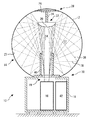
図1は、本発明に基づくシステム10の立断面図であり、このシステム10は、単一の投影機を使用して、好適には、実質的に球形の空間17を取り囲む中空球状の三次元スクリーン14の外側表面12に映像を作成するものである。スクリーン14はベース16の上に載置される。ベース16内に設けた投影機18が、スクリーン14の開口19を通して上向きに、スクリーン14に取り付けられた取付板26から下方へ延びる棒24に懸架された鏡22の下面20に向かって映像を投影する。投影機18及び開口19並びに鏡22は、スクリーン14の共通軸沿いに存在する。鏡22の凸状の下面20が投影された像を反射し、その像をスクリーン14のほぼ全内面27に放射する。スクリーン14は半透明であるので、スクリーンのうちで鏡22あるいはベース16によりぼかされる投影軸線沿いの領域28及び30を除くほぼ全部の外側表面12に、その映像が現れる。システム10の高さが十分にある場合には、スクリーンの隣に立つ人間は、上部領域28における映像の途切れに気づかない。凸面鏡22の鏡面は球形の幾何形状若しくは楕円形の幾何形状のいずれでもよい。凸状虚焦点面を有する投影機レンズに関連して使用される球面鏡、あるいは平面状虚焦点面を有する投影機に関連して使用される楕円面鏡は、適当な深度の焦点をもっており、像が現れるスクリーン14上のどこでも明瞭な表示像を与える。必要であれば、スクリーンと放射鏡の幾何学形状とに起因して生じるいかなる歪みをも補償すべく、投影機18によって作成された映像は予め適切に歪めておき、スクリーン14上に投影されたときに正確な映像が現れるようにすることができる。
DETAILED DESCRIPTION OF THE INVENTION FIG. 1 is an elevational cross-sectional view of a
図1は投影機18から出た投影光が鏡の下面20に至る光路34と、反射された光が鏡の下面20からスクリーン内面27に至る光路36とを例示している。スクリーンの内面27がわずかに反射する仕上げになっていると、スクリーンの内面27に当たった光のごく一部は反射され、半透明材料のスクリーンを通過して外に出ることはない。反射光のほとんどは光路38を通って黒い円筒状の光遮蔽体40に向かうが、この光遮蔽体40はベース16から鏡22向けて上に延出し、投影機18から出る光線を取り囲む。光遮蔽体40は、前記内面27から反射される光を吸収し、その光がスクリーン内面27の他の部分に達してゴースト映像を発生することを防ぐ。
FIG. 1 illustrates an optical path 34 where the projection light emitted from the
投影機18は、静止画や動画を作成するための、フィルム投影機又はディジタル投影機若しくは他のいかなる種類の投影機でもよい。図1に例示した発明の実施の形態では、やはりベース16内に搭載されたコンピュータ42によって提供されるビデオデータに基づいて映像を作成するためのディジタル投影機である。ベース16に設けたドア(図示せず)は、投影機18とコンピュータ42へのアクセスを容易にする。
The
図2及び図3は、それぞれ、図1に示す鏡22を取り付けるための別のシステムの平面図と立断面図である。図1に示すようにスクリーン14の内面27に取り付けられたプレート26から下方に延出する棒24に鏡22を懸架するよりも、図2及び図3に示す別の取り付けシステムは、光遮蔽体40から上方へ延びる中央の棒52を使用して鏡22を下から支持する。この支持棒52はそれ自体が、投影光の妨害を最小限にとどめるように整合された光遮蔽体40内に、薄いフィン53によって支持される。
2 and 3 are a plan view and an elevational sectional view, respectively, of another system for mounting the
図4は、ベース76上に載置された半透明の球形スクリーン70を有する投影システム60を示すが、これは多くの点で図1のシステム10に類似する。しかしながら、投影システム60は、ベース76内において一台の投影機ではなく二台の投影機62及び64を使用して、より明るい表示像を与える。ベース76から上に延出する中央の棒73に支持された鏡66の下側の凸面は、投影機62から来る光線を、主としてスクリーン70の下半球68の内面上に亘って放射する。スクリーン70の頂点内面に取り付けた第二の鏡72は、投影機64から来る光線を、上向きにされた第3の鏡67の凸面に向かって反射するように傾斜を有しており、この鏡67がその映像を主としてスクリーン70の上半球74の内面上に亘って放射する。投影機62及び鏡66,67,72は、スクリーン70によって取り囲まれた空間の垂直軸に沿って存在するが、一方、投影機64はその軸線からずれており、その光線を、該垂直軸と鏡72の位置で交差する光路に向かわせる。好適な実施の形態では、投影機62,64は、ベース76内に設置したコンピュータ78によって制御されるディジタル投影機である。しかし、投影機62及び64は、任意の種類の投影機でよい。
4 shows a
ゴースト映像が中央の鏡66,67に向けて反射し戻されるので、そのゴースト映像は図4に示す複式投影機方式の場合にはさほど問題にならない。したがって、このシステムの複式投影機方式は、光遮蔽体40に機能上類似した光遮蔽体を有しない。しかし、スクリーン70の内面から反射された光を遮るように適切な形状、配置、大きさにした光遮蔽体を設けてゴーストを低減することができることは明白であろう。
Since the ghost image is reflected back toward the
図5は、本発明の一つの実施の形態の略式立断面図であり、この実施の形態は、投影機90がスクリーンに近接したベース内に取り付けられるよりもむしろ球面スクリーン92から離隔して配置されていることを除いて、図1の単一投影システム10の光学系と全体的に類似する光学系を有する。スクリーン92によって取り囲まれた空間の内外いずれの側から映像を見るべきかに応じて、スクリーン92は半透明又は不透明にされる。
FIG. 5 is a schematic elevational view of one embodiment of the present invention that is spaced apart from the
図6は、本発明の一つの実施の形態の略式立断面図であり、この実施の形態は、投影機94が球形スクリーン96の外部に配置されるよりむしろその内部に配置されることを除いて、図1の単一投影システム10の光学系と全体として類似する光学系を有する。スクリーン96によって取り囲まれた空間の内外いずれの側から映像を見るべきかに応じて、スクリーン96は半透明又は不透明にされる。
FIG. 6 is a schematic elevational cross-sectional view of one embodiment of the present invention, except that the
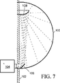
図7は、本発明の一つの実施の形態の略式立断面図であり、この実施の形態は壁102上に装着された半透明の半球形スクリーン100の外側表面に表示像を作成するものである。スクリーン100の背後で壁102に埋め込まれた投影機104が、スクリーン100内部の鏡106に向かって映像を投影する。鏡106は、壁102に装着された凸面鏡108上に向かって映像を反射し、この鏡108が透過スクリーン100の内面上に亘って映像を放射し、その結果当該映像がその外側表面に現れる。
FIG. 7 is a schematic elevational view of one embodiment of the present invention, which creates a display image on the outer surface of a translucent
図8は、本発明の別の実施の形態の略式立断面図であり、この実施の形態は壁112上に装着された半透明の半球形スクリーン110の外側表面上に表示像を作成するものである。スクリーン110の下端部の背後において壁112に埋め込まれた投影機114が、スクリーン100の内部の鏡116に向かって映像を投影する。鏡116は、壁112上に装着された凸面鏡118に向かって映像を反射し、この凸面鏡118がスクリーン110の内面のうちの下半分に亘って映像を放射する。スクリーン110上端部の背後において壁112に埋め込まれた別の投影機120が、鏡122に第二の映像を投影し、この鏡122がその映像を鏡118に向かって反射する。鏡118は、スクリーン110内面のうちの上半分に亘ってその第二の映像を放射する。凸面鏡118と組み合わせた図8の二台の投影機は、図7の単一投影機半球システムによって提供されるものよりももっと明るく、より精細な映像を半球形スクリーン110上に提供する。複式投影機の利点を結合して明るさと精細さを得るために、二台以上の投影機を単一の凸面鏡又は一対の凸面鏡へ向けて投影させることができることは明白であろう。
FIG. 8 is a schematic elevational view of another embodiment of the present invention that creates a display image on the outer surface of a translucent
一台又はそれ以上の投影機からの映像を反射して、半透明又は不透明のいずれでもよい球形若しくは半球形のスクリーンの内面のほぼ全体に亘りその映像を放射する凸面放射鏡を使用するシステムの好ましい実施例を図示し、説明してきた。この凸面反射体構成は、投影機(単数又は複数)がスクリーンの一端にのみ位置する場合でも、映像がスクリーン表面のほぼ全面をカバーすることを可能にする。 Of a system using a convex radiator that reflects an image from one or more projectors and emits the image over substantially the entire inner surface of a spherical or hemispherical screen that may be either translucent or opaque. The preferred embodiment has been illustrated and described. This convex reflector configuration allows the image to cover almost the entire screen surface, even when the projector or projectors are located only at one end of the screen.
上記は本発明の好適な実施の形態を説明してきたが、当該業界において通常の技量を有する技術者は、本発明から逸脱することなくより広範な点で上記好適な実施の形態に多くの改変を施すことができる。例えば、同様のシステムを使用して、円筒形や多面体などの他の形をした三次元スクリーンに投影像を作成することができる。したがって、添付の特許請求の範囲は、本発明の真の範囲及びその精神に属するすべての改変に及ぶものである。 Although the foregoing has described preferred embodiments of the invention, those skilled in the art will recognize that many modifications to the preferred embodiments may be made in a broader respect without departing from the invention. Can be applied. For example, a similar system can be used to create a projected image on a three-dimensional screen of other shapes such as a cylinder or polyhedron. Accordingly, the appended claims are intended to cover all modifications within the true scope and spirit of this invention.
Claims (18)
第一の映像を投影する第一の投影手段と、
前記三次元空間内に配設された第一の凸面を有する第一の鏡であって、前記第一の映像を反射し、更に、前記スクリーンの内側表面に亘って前記第一の映像を放射して、前記スクリーンの内側表面に亘って放射された前記第一の映像が前記スクリーンの外側表面に現れるようにしたものと、
前記スクリーンの内側表面で反射された光を吸収するために、前記三次元空間内に配置された光遮蔽体であって、前記第一の映像が前記第一の投影手段と第一の鏡の間においてとる光路の一部を取り囲むものを具備することを特徴とする映像表示装置。A screen having an outer surface and composed of a translucent material having an inner surface substantially surrounding a three-dimensional space;
First projecting means for projecting a first image;
A first mirror having a first convex surface disposed in the three-dimensional space, which reflects the first image and further radiates the first image across an inner surface of the screen; The first image emitted over the inner surface of the screen appears on the outer surface of the screen ;
A light shield disposed in the three-dimensional space for absorbing the light reflected by the inner surface of the screen, wherein the first image is formed by the first projection means and the first mirror; An image display device comprising a device surrounding a part of an optical path taken in between .
前記第一の投影手段が実質的に閉じた前記三次元空間の外側に存在し、
前記第一の投影手段が前記スクリーンの開口を通して前記第一の鏡の第一の凸面へ前記第一の映像を投影することを特徴とする前記請求項1に記載の映像表示装置。The screen has an opening;
The first projection means is outside the substantially closed three-dimensional space;
The image display apparatus according to claim 1, wherein the first projection unit projects the first image onto the first convex surface of the first mirror through the opening of the screen.
前記第一の投影手段及び第一の鏡が前記中心軸に沿って存在することを特徴とする前記請求項1乃至3のうちのいずれか1項に記載の映像表示装置。The screen is formed into a hollow sphere having a central axis;
4. The video display device according to claim 1, wherein the first projection unit and the first mirror exist along the central axis. 5.
該半球形の空間内に配設された第一の鏡と、A first mirror disposed in the hemispherical space;
第一の映像を前記第一の鏡に投影して、前記第一の鏡が前記第一の映像を反射するようにする第一の投影手段と、First projecting means for projecting a first image onto the first mirror so that the first mirror reflects the first image;
前記半球形の空間内に配設された第一の凸面を有する第二の鏡であって、前記第一の鏡によって反射された前記第一の映像を受けて前記第一の映像を反射し、更に、前記スクリーンの内側表面に亘って前記第一の映像を放射して、前記スクリーンの内側表面に亘って放射された前記第一の映像が前記スクリーンの外側表面に現れるようにしたものを具備することを特徴とする映像表示装置。A second mirror having a first convex surface disposed in the hemispherical space, receiving the first image reflected by the first mirror and reflecting the first image; And radiating the first image over the inner surface of the screen so that the first image radiated over the inner surface of the screen appears on the outer surface of the screen. A video display device comprising:
前記半球形の空間内に配設される第三の鏡であって、前記第二の投影手段によって投影された前記第二の映像を受けて、該第二の映像を反射するものと、 A third mirror disposed in the hemispherical space, receiving the second image projected by the second projection means, and reflecting the second image;
前記半球形の空間内に配設される、第二の凸面を有する第四の鏡であって、前記第三の鏡によって反射された第二の画像を受けて前記第二の映像を反射して前記スクリーンの内側表面上に前記第二の映像を放射するものを具備することを特徴とする前記請求項8又は9に記載の映像表示装置。A fourth mirror having a second convex surface disposed in the hemispherical space, receiving the second image reflected by the third mirror and reflecting the second image; The image display device according to claim 8, further comprising: a device that emits the second image on an inner surface of the screen.
第一の映像を投影する第一の投影手段と、
前記三次元空間内に配設された、第一の凸面を有する第一の鏡であって、前記第一の映像を反射して、前記スクリーンの内側表面に亘って前記第一の映像を放射するものと、
第二の映像を投影する第二の投影手段と、
前記三次元空間内に配設された、第二の凸面を有する第二の鏡と、
実質的に閉じた前記三次元空間内に取り付けられた第三の鏡であって、前記第二の映像を前記第二の鏡の前記第二の凸面上に反射するものと、を具備し、
前記第二の鏡が前記第二の映像を反射して、前記第二の映像を前記スクリーンの内側表面に放射するために配置されることを特徴とする映像表示装置。 A screen having an inner surface substantially surrounding the three-dimensional space;
First projecting means for projecting a first image;
A first mirror having a first convex surface disposed in the three-dimensional space, reflecting the first image and radiating the first image over an inner surface of the screen; What to do,
A second projection means for projecting a second image;
A second mirror having a second convex surface disposed in the three-dimensional space;
A third mirror mounted in the substantially closed three-dimensional space, the second mirror reflecting the second image on the second convex surface of the second mirror,
The video display device, wherein the second mirror is arranged to reflect the second video and to radiate the second video to an inner surface of the screen .
前記第一の鏡が前記第一の投影手段と第二の鏡の間に存在した状態で、前記第一の投影手段及び前記第一の鏡並びに前記第二の鏡が、前記3次元空間の中心軸に沿って存在し、With the first mirror existing between the first projection means and the second mirror, the first projection means, the first mirror, and the second mirror are in the three-dimensional space. Exists along the central axis,
該第二の投影手段が、前記中心軸に交差する光路に沿って前記第二の映像を投影することを特徴とする前記請求項12又は13に記載の映像表示装置。14. The image display apparatus according to claim 12, wherein the second projecting unit projects the second image along an optical path intersecting the central axis.
該半球形の空間内に配設された第一の鏡と、A first mirror disposed in the hemispherical space;
第一の映像を前記第一の鏡に投影して、前記第1の鏡が前記第一の映像を反射する第一の投影手段と、First projection means for projecting a first image onto the first mirror, and wherein the first mirror reflects the first image;
前記半球形の空間内に配設された、第一の凸面を有する第二の鏡であって、前記第一の鏡によって反射された前記第一の映像を受けて、前記第一の映像を反射して、前記スクリーンの内側表面に亘って前記第一の映像を放射するものと、A second mirror having a first convex surface disposed in the hemispherical space, receiving the first image reflected by the first mirror, Reflecting and radiating the first image across the inner surface of the screen;
第二の映像を投影するための第二の投影手段と、A second projection means for projecting a second image;
前記半球形空間内に配設された第三の鏡であって、前記第二の投影手段により投影された前記第二の映像を受けて、前記第二の映像を反射するものと、A third mirror disposed in the hemispherical space that receives the second image projected by the second projection means and reflects the second image;
前記半球形空間内に配設された、第二の凸面を有する第四の鏡であって、前記第三の鏡によって反射された前記第二の映像を受けて、該第二の映像を反射し、前記スクリーンの内側表面上に亘って前記第二の映像を放射するものを有することを特徴とする映像表示装置。A fourth mirror having a second convex surface disposed in the hemispherical space, receiving the second image reflected by the third mirror and reflecting the second image; And an image display device that emits the second image over the inner surface of the screen.
Applications Claiming Priority (2)
| Application Number | Priority Date | Filing Date | Title |
|---|---|---|---|
| US09/781,935 US6409351B1 (en) | 2001-02-12 | 2001-02-12 | Spherical image projection system using a convex reflecting image dispersing element |
| PCT/US2002/003259 WO2002065207A1 (en) | 2001-02-12 | 2002-01-31 | Spherical image projection system using a convex reflecting image dispersing element |
Related Child Applications (1)
| Application Number | Title | Priority Date | Filing Date |
|---|---|---|---|
| JP2007186201A Division JP2008020920A (en) | 2001-02-12 | 2007-07-17 | Spherical image projection system using convex reflecting image dispersing element |
Publications (3)
| Publication Number | Publication Date |
|---|---|
| JP2004530148A JP2004530148A (en) | 2004-09-30 |
| JP2004530148A5 JP2004530148A5 (en) | 2005-12-22 |
| JP4002835B2 true JP4002835B2 (en) | 2007-11-07 |
Family
ID=25124431
Family Applications (2)
| Application Number | Title | Priority Date | Filing Date |
|---|---|---|---|
| JP2002564665A Expired - Fee Related JP4002835B2 (en) | 2001-02-12 | 2002-01-31 | Spherical image projection system using image reflection radiation convex surface member |
| JP2007186201A Pending JP2008020920A (en) | 2001-02-12 | 2007-07-17 | Spherical image projection system using convex reflecting image dispersing element |
Family Applications After (1)
| Application Number | Title | Priority Date | Filing Date |
|---|---|---|---|
| JP2007186201A Pending JP2008020920A (en) | 2001-02-12 | 2007-07-17 | Spherical image projection system using convex reflecting image dispersing element |
Country Status (4)
| Country | Link |
|---|---|
| US (1) | US6409351B1 (en) |
| EP (1) | EP1368706A4 (en) |
| JP (2) | JP4002835B2 (en) |
| WO (1) | WO2002065207A1 (en) |
Families Citing this family (40)
| Publication number | Priority date | Publication date | Assignee | Title |
|---|---|---|---|---|
| US7021937B2 (en) * | 2000-04-14 | 2006-04-04 | Viretek | Race car simulator |
| DE10036570B4 (en) * | 2000-07-27 | 2004-07-15 | Robert Bosch Gmbh | display device |
| US6554434B2 (en) * | 2001-07-06 | 2003-04-29 | Sony Corporation | Interactive projection system |
| US20050174645A1 (en) * | 2002-04-23 | 2005-08-11 | Magna Donnelly Mirrors North America | Vehicle mirror having polymeric reflective film element and self-dimming element |
| EP1540965A1 (en) * | 2002-09-19 | 2005-06-15 | Elumens Corporation | Systems and methods for full hemispherical projection using multiple projectors that generate multiple arrays of image pixels that overlap along a single edge |
| US6865023B2 (en) * | 2002-10-29 | 2005-03-08 | Eugene Lee Shafer | System for collecting and displaying images to create a visual effect and methods of use |
| US7352340B2 (en) * | 2002-12-20 | 2008-04-01 | Global Imagination | Display system having a three-dimensional convex display surface |
| DE10316227B3 (en) * | 2003-04-09 | 2004-07-22 | Savage, Charles M., Dr. | Interactive visual presentation space for images, graphics, words and characters with display surfaces positioned above and below transparent floor surface |
| US7118228B2 (en) * | 2003-11-04 | 2006-10-10 | Hewlett-Packard Development Company, L.P. | Image display system |
| JP4583907B2 (en) * | 2004-12-17 | 2010-11-17 | 日本電信電話株式会社 | Video drawing apparatus and video drawing method |
| US7416308B2 (en) * | 2005-02-16 | 2008-08-26 | Mr. Christmas Inc. | Panoramic motion projector |
| US7766483B2 (en) | 2005-04-06 | 2010-08-03 | Suresh Balu | Optical projection system and methods for configuring the same |
| CN101360874B (en) * | 2005-07-29 | 2010-09-29 | 埃鲁麦那提有限责任公司 | Dual pressure inflatable structure and method |
| US8049960B1 (en) | 2006-02-13 | 2011-11-01 | Ligon Thomas R | Contrast rear projection screen and method for manufacturing the same |
| US7604354B1 (en) * | 2006-05-10 | 2009-10-20 | Ligon Thomas R | Three-dimensional projection apparatus using coaxial optical alignment |
| WO2007149333A2 (en) * | 2006-06-16 | 2007-12-27 | Alphacurve, Inc. | Curved screen display system and method |
| US7621647B1 (en) * | 2006-06-23 | 2009-11-24 | The Elumenati, Llc | Optical projection system and method of use |
| GB2442019B (en) * | 2006-09-21 | 2009-02-25 | Thales Holdings Uk Plc | Image display system and method |
| CA2632346A1 (en) | 2006-10-06 | 2008-04-10 | Lalley Brothers Scientific Llc | Three-dimensional internal back-projection system and method for using the same |
| US20080204666A1 (en) * | 2007-02-02 | 2008-08-28 | Robert Spearman | Image projection and capture systems |
| FR2919934B1 (en) * | 2007-08-09 | 2010-09-17 | Univ Clermont Auvergne | PANORAMIC PROJECTION DEVICE AND METHOD USED THEREIN |
| US8884883B2 (en) * | 2008-01-25 | 2014-11-11 | Microsoft Corporation | Projection of graphical objects on interactive irregular displays |
| US8016426B2 (en) * | 2008-02-27 | 2011-09-13 | 6115187 Canada Inc. | Method and device for projecting a panoramic image with a variable resolution |
| JP4409618B2 (en) * | 2008-06-04 | 2010-02-03 | 暁 吉井 | Full-field projection device and full-field image system |
| US8500284B2 (en) | 2008-07-10 | 2013-08-06 | Real View Imaging Ltd. | Broad viewing angle displays and user interfaces |
| US9218116B2 (en) * | 2008-07-25 | 2015-12-22 | Hrvoje Benko | Touch interaction with a curved display |
| US8646918B2 (en) | 2009-01-30 | 2014-02-11 | Old Dominion University Research Foundation | Projection system |
| US8210686B2 (en) * | 2009-01-30 | 2012-07-03 | Old Dominion University Research Foundation | Projection system |
| US8446367B2 (en) * | 2009-04-17 | 2013-05-21 | Microsoft Corporation | Camera-based multi-touch mouse |
| JP4819960B1 (en) * | 2010-08-24 | 2011-11-24 | 暁 吉井 | Full-field projection device and full-field image system |
| JP5134706B2 (en) * | 2011-05-16 | 2013-01-30 | 日本写真印刷株式会社 | Curved touch panel, manufacturing method thereof, and display device with curved touch panel |
| US8562145B2 (en) * | 2011-06-22 | 2013-10-22 | 3M Innovative Properties Company | Display system and method for projection onto non-planar surfaces |
| US20130033650A1 (en) * | 2011-08-02 | 2013-02-07 | 3M Innovative Properties Company | Display system and method for projection onto multiple surfaces |
| US20150062294A1 (en) * | 2013-08-27 | 2015-03-05 | Thomas S. Sibley | Holoscope: Digital Virtual Object Projector |
| WO2017047126A1 (en) * | 2015-09-15 | 2017-03-23 | シャープ株式会社 | Projection device |
| USD849819S1 (en) * | 2017-03-14 | 2019-05-28 | Umbo, Inc. | Smart projection system |
| CN111127998A (en) * | 2020-01-07 | 2020-05-08 | 北京小米移动软件有限公司 | Intelligent globe, control method of intelligent globe and storage medium |
| EP3995891A1 (en) | 2020-11-04 | 2022-05-11 | Christesen Matz | Device for internal projection |
| US20230338829A1 (en) * | 2022-04-21 | 2023-10-26 | Sony Interactive Entertainment Inc. | Single unit deformable controller |
| US20240069424A1 (en) * | 2022-08-23 | 2024-02-29 | Applied Physics, Inc. | Light sphere dome |
Family Cites Families (12)
| Publication number | Priority date | Publication date | Assignee | Title |
|---|---|---|---|---|
| US2510080A (en) * | 1946-03-18 | 1950-06-06 | Lawrence J Cuneo | Optical projection system |
| US2592444A (en) | 1950-04-12 | 1952-04-08 | John J Matelena | Inflatable aerial projection display device |
| US3586432A (en) | 1969-04-01 | 1971-06-22 | Pentes Design Inc | Self-contained image projecting apparatus and rear projection screen therefor |
| US4427274A (en) | 1981-04-15 | 1984-01-24 | Mcdonnell Douglas Corporation | Wide angle projection system |
| FR2588684B1 (en) | 1985-10-10 | 1988-01-08 | Nicolas Pierre | PROJECTION APPARATUS WITH SPHERICAL SCREEN MORE ESPECIALLY FOR ADVERTISING USES |
| DE19500693A1 (en) * | 1995-01-12 | 1996-07-18 | Bke Bildtechnik Inh Ernst Stec | Advertising or information display system |
| US6141034A (en) * | 1995-12-15 | 2000-10-31 | Immersive Media Co. | Immersive imaging method and apparatus |
| US6042238A (en) * | 1996-01-17 | 2000-03-28 | Seos Displays Limited | Image projection display system for use in large field-of-view presentation |
| US5762413A (en) * | 1996-01-29 | 1998-06-09 | Alternate Realities Corporation | Tiltable hemispherical optical projection systems and methods having constant angular separation of projected pixels |
| US5760826A (en) * | 1996-05-10 | 1998-06-02 | The Trustees Of Columbia University | Omnidirectional imaging apparatus |
| JP2916142B1 (en) * | 1998-08-10 | 1999-07-05 | 洋夫 岩田 | All-round spherical screen projector |
| US6286962B1 (en) * | 1998-12-23 | 2001-09-11 | Thomas Hennes, Inc. | Beamsplitter optical projection system |
-
2001
- 2001-02-12 US US09/781,935 patent/US6409351B1/en not_active Expired - Lifetime
-
2002
- 2002-01-31 WO PCT/US2002/003259 patent/WO2002065207A1/en active Application Filing
- 2002-01-31 JP JP2002564665A patent/JP4002835B2/en not_active Expired - Fee Related
- 2002-01-31 EP EP02703335A patent/EP1368706A4/en not_active Ceased
-
2007
- 2007-07-17 JP JP2007186201A patent/JP2008020920A/en active Pending
Also Published As
| Publication number | Publication date |
|---|---|
| JP2008020920A (en) | 2008-01-31 |
| EP1368706A4 (en) | 2007-04-25 |
| JP2004530148A (en) | 2004-09-30 |
| US6409351B1 (en) | 2002-06-25 |
| WO2002065207A1 (en) | 2002-08-22 |
| EP1368706A1 (en) | 2003-12-10 |
Similar Documents
| Publication | Publication Date | Title |
|---|---|---|
| JP4002835B2 (en) | Spherical image projection system using image reflection radiation convex surface member | |
| JP2004530148A5 (en) | ||
| US6327020B1 (en) | Full-surround spherical screen projection system and recording apparatus therefor | |
| US2304434A (en) | Projecting device | |
| JPH06347749A (en) | Low-profile type liquid crystal projector and application thereof | |
| JP2006317708A (en) | Airborne video projector | |
| US4294515A (en) | Virtual image display apparatus | |
| JP2008070694A (en) | Projection system | |
| RU2007108944A (en) | VISUAL DISPLAY DEVICE | |
| US4338006A (en) | Overhead projector | |
| JPH061295B2 (en) | Light projection device | |
| CA2107127C (en) | An apparatus for generating three-dimensional images | |
| US20010036025A1 (en) | Three dimensional real image system | |
| KR20130022968A (en) | Projector | |
| CN105607405B (en) | A kind of projection screen | |
| JP2009053644A (en) | Bag type presentation apparatus | |
| US7055960B2 (en) | Rear projection display device | |
| JP4999386B2 (en) | Vehicle with rear camera | |
| JP2013064876A (en) | Image display device | |
| JP7061260B2 (en) | Screen and projection system | |
| JP2004029849A5 (en) | ||
| JP2005208308A (en) | Stereoscopic projector | |
| JPH0438346Y2 (en) | ||
| CN110412822A (en) | Three-dimensional flat-panel display device | |
| JP2013061375A (en) | Image display device |
Legal Events
| Date | Code | Title | Description |
|---|---|---|---|
| A521 | Request for written amendment filed |
Free format text: JAPANESE INTERMEDIATE CODE: A523 Effective date: 20041224 |
|
| A621 | Written request for application examination |
Free format text: JAPANESE INTERMEDIATE CODE: A621 Effective date: 20041224 |
|
| RD04 | Notification of resignation of power of attorney |
Free format text: JAPANESE INTERMEDIATE CODE: A7424 Effective date: 20060712 |
|
| A977 | Report on retrieval |
Free format text: JAPANESE INTERMEDIATE CODE: A971007 Effective date: 20061213 |
|
| A131 | Notification of reasons for refusal |
Free format text: JAPANESE INTERMEDIATE CODE: A131 Effective date: 20061219 |
|
| A521 | Request for written amendment filed |
Free format text: JAPANESE INTERMEDIATE CODE: A523 Effective date: 20070319 |
|
| A131 | Notification of reasons for refusal |
Free format text: JAPANESE INTERMEDIATE CODE: A131 Effective date: 20070417 |
|
| A521 | Request for written amendment filed |
Free format text: JAPANESE INTERMEDIATE CODE: A523 Effective date: 20070717 |
|
| TRDD | Decision of grant or rejection written | ||
| A01 | Written decision to grant a patent or to grant a registration (utility model) |
Free format text: JAPANESE INTERMEDIATE CODE: A01 Effective date: 20070814 |
|
| A61 | First payment of annual fees (during grant procedure) |
Free format text: JAPANESE INTERMEDIATE CODE: A61 Effective date: 20070820 |
|
| FPAY | Renewal fee payment (event date is renewal date of database) |
Free format text: PAYMENT UNTIL: 20100824 Year of fee payment: 3 |
|
| R150 | Certificate of patent or registration of utility model |
Free format text: JAPANESE INTERMEDIATE CODE: R150 |
|
| FPAY | Renewal fee payment (event date is renewal date of database) |
Free format text: PAYMENT UNTIL: 20110824 Year of fee payment: 4 |
|
| FPAY | Renewal fee payment (event date is renewal date of database) |
Free format text: PAYMENT UNTIL: 20110824 Year of fee payment: 4 |
|
| FPAY | Renewal fee payment (event date is renewal date of database) |
Free format text: PAYMENT UNTIL: 20120824 Year of fee payment: 5 |
|
| LAPS | Cancellation because of no payment of annual fees |