JP4001876B2 - Lifeline attachment device for roof work - Google Patents
Lifeline attachment device for roof work Download PDFInfo
- Publication number
- JP4001876B2 JP4001876B2 JP2004116700A JP2004116700A JP4001876B2 JP 4001876 B2 JP4001876 B2 JP 4001876B2 JP 2004116700 A JP2004116700 A JP 2004116700A JP 2004116700 A JP2004116700 A JP 2004116700A JP 4001876 B2 JP4001876 B2 JP 4001876B2
- Authority
- JP
- Japan
- Prior art keywords
- roof
- eaves
- rod
- leg
- bar
- Prior art date
- Legal status (The legal status is an assumption and is not a legal conclusion. Google has not performed a legal analysis and makes no representation as to the accuracy of the status listed.)
- Expired - Lifetime
Links
- 239000000725 suspension Substances 0.000 claims description 48
- 230000007246 mechanism Effects 0.000 claims description 17
- 230000003014 reinforcing effect Effects 0.000 claims description 4
- 230000008878 coupling Effects 0.000 claims description 2
- 238000010168 coupling process Methods 0.000 claims description 2
- 238000005859 coupling reaction Methods 0.000 claims description 2
- 239000000463 material Substances 0.000 description 25
- 238000009434 installation Methods 0.000 description 16
- 229910052751 metal Inorganic materials 0.000 description 12
- 239000002184 metal Substances 0.000 description 12
- 230000000087 stabilizing effect Effects 0.000 description 11
- 238000003780 insertion Methods 0.000 description 9
- 230000037431 insertion Effects 0.000 description 9
- 241000234314 Zingiber Species 0.000 description 7
- 235000006886 Zingiber officinale Nutrition 0.000 description 7
- 235000008397 ginger Nutrition 0.000 description 7
- 238000000926 separation method Methods 0.000 description 7
- 230000002093 peripheral effect Effects 0.000 description 4
- 230000002265 prevention Effects 0.000 description 3
- 230000000007 visual effect Effects 0.000 description 3
- 229910000838 Al alloy Inorganic materials 0.000 description 2
- 206010048744 Fear of falling Diseases 0.000 description 2
- 229910000831 Steel Inorganic materials 0.000 description 2
- 235000009508 confectionery Nutrition 0.000 description 2
- 230000005484 gravity Effects 0.000 description 2
- 238000000034 method Methods 0.000 description 2
- 239000010959 steel Substances 0.000 description 2
- 239000013585 weight reducing agent Substances 0.000 description 2
- 125000002066 L-histidyl group Chemical group [H]N1C([H])=NC(C([H])([H])[C@](C(=O)[*])([H])N([H])[H])=C1[H] 0.000 description 1
- 230000009471 action Effects 0.000 description 1
- 229910052782 aluminium Inorganic materials 0.000 description 1
- XAGFODPZIPBFFR-UHFFFAOYSA-N aluminium Chemical compound [Al] XAGFODPZIPBFFR-UHFFFAOYSA-N 0.000 description 1
- 230000004323 axial length Effects 0.000 description 1
- 230000008901 benefit Effects 0.000 description 1
- 239000004566 building material Substances 0.000 description 1
- 238000010276 construction Methods 0.000 description 1
- 230000008602 contraction Effects 0.000 description 1
- 238000004132 cross linking Methods 0.000 description 1
- 230000007423 decrease Effects 0.000 description 1
- 238000006073 displacement reaction Methods 0.000 description 1
- 230000000694 effects Effects 0.000 description 1
- PCHJSUWPFVWCPO-UHFFFAOYSA-N gold Chemical compound [Au] PCHJSUWPFVWCPO-UHFFFAOYSA-N 0.000 description 1
- 239000010931 gold Substances 0.000 description 1
- 229910052737 gold Inorganic materials 0.000 description 1
- 238000004519 manufacturing process Methods 0.000 description 1
- 230000000149 penetrating effect Effects 0.000 description 1
- 230000035515 penetration Effects 0.000 description 1
- 230000007480 spreading Effects 0.000 description 1
- 238000003892 spreading Methods 0.000 description 1
- 239000010935 stainless steel Substances 0.000 description 1
- 229910001220 stainless steel Inorganic materials 0.000 description 1
- 238000003466 welding Methods 0.000 description 1
Images


Description
本発明は、傾斜した屋根上での作業を安全に行うことができる屋根作業用命綱取り付け装置に関する。 The present invention relates to a lifeline attaching device for roof work that can safely perform work on an inclined roof.
傾斜した屋根上での作業は作業者が落下する危険を伴うため、作業に際しては落下を防止するため装置を設置する必要がある。従来、落下を防止する装置としては、軒下の地面から足場を組み上げることが一般的に行われていた。また、かかる軒下足場に加えて、屋根面の上にも足場を設けて安全性を確保する場合もあった(例えば、特許文献1参照。)。 Since work on an inclined roof involves the danger of an operator falling, it is necessary to install a device in order to prevent the work from falling. Conventionally, as a device for preventing a fall, it has been generally performed to assemble a scaffold from the ground under the eaves. Further, in addition to the eaves scaffold, a scaffold may be provided on the roof surface to ensure safety (see, for example, Patent Document 1).
また、かかる足場の代わりに、屋根の棟に命綱取り付け用のアンカーを打ち込んだり、屋根上に張設されたロープに命綱を掛けたりして安全性を確保する場合もあった。(例えば、特許文献2参照。)。 In some cases, instead of such scaffolding, safety is secured by driving an anchor for attaching a lifeline into a roof ridge or hanging a lifeline on a rope stretched on the roof. (For example, refer to Patent Document 2).
しかしながら、地面から足場を組み立てる場合、その設置には膨大なコストと労力を必要とし、特に高層建築の場合にはそれが顕著である。また足場を組み立てるため工期も極めて長くなってしまう。また、地面から足場を組み立てると、高層階であっても足場を経由して建物内に侵入可能な状態となるため、防犯上問題がある他、建物内の窓等から外を見る際に足場が見える状態となるから建物の居住性、快適性を損なうことにもなる。また、屋根の上に足場を設ける場合、瓦やシングル等の屋根材を葺く場合などに当該足場が邪魔になって作業ができず、又は作業性が著しく低下する。一方、棟に固定したアンカーから下ろした命綱や、屋根上に張設されたロープによる安全装置では、コストは低いものの、安全性の確保が十分ではない。即ち、ロープや命綱が長くなるため、作業者は不安定な状態となり、作業性が極めて悪くなる。また長いロープに足を取られて転倒する可能性もあり、安全性の高いものとはならない。 However, when a scaffold is assembled from the ground, its installation requires enormous costs and labor, especially in the case of high-rise buildings. Moreover, since the scaffold is assembled, the construction period becomes extremely long. Also, when the scaffold is assembled from the ground, it can enter the building via the scaffold even if it is on a higher floor, so there is a problem in terms of crime prevention, as well as a scaffold when looking out from the window inside the building. Because it becomes visible, it will impair the comfort and comfort of the building. In addition, when a scaffold is provided on the roof, when the roof material such as a tile or a single is sown, the scaffold becomes in the way and the work cannot be performed, or the workability is remarkably reduced. On the other hand, a lifeline lowered from an anchor fixed to a building or a safety device using a rope stretched on a roof is low in cost, but safety is not sufficient. That is, since the rope and the lifeline become long, the worker becomes unstable and the workability becomes extremely poor. In addition, there is a possibility of falling over a long rope, so it is not safe.
本発明は、かかる状況に鑑みてなされたものであり、極めて安全性が高く、かつ低コストで、しかも容易に設置でき、さらに屋根作業が行いやすい屋根作業用命綱取り付け装置を提供することを目的とする。 The present invention has been made in view of such a situation, and an object of the present invention is to provide a lifeline attachment device for roofing work that is extremely safe, can be easily installed at a low cost, and is easy to perform roofing work. And
上記の目的を達成するため、本発明では、傾斜した屋根の棟部に略沿って固定されるアンカー部材と、
前記アンカー部材と連結し屋根の傾斜に沿って屋根の棟部から軒先にむかって設けられる複数本の梁棒と、
隣り合った梁棒相互間を架橋する複数本のつなぎ棒と、
屋根上面に載置され前記梁棒を支持する複数の脚体と、
を有し、
前記梁棒又はつなぎ棒に命綱を取り付ける命綱取り付け装置であって、
前記脚体は、他の脚体を屋根上面に載置した状態で個別的に屋根上面と離間しうる離間機構を有しており、且つ、前記梁棒は、その上側端部付近に長手方向に沿って複数のボルト穴を備えることにより、他部材との連結位置を調整可能としていることを特徴とする屋根作業用命綱取り付け装置としている。
In order to achieve the above object, in the present invention, an anchor member fixed substantially along a ridge portion of an inclined roof,
A plurality of beam bars connected to the anchor member and provided from the roof ridge to the eaves along the slope of the roof;
A plurality of connecting rods that bridge between adjacent beam bars;
A plurality of legs mounted on the roof top surface and supporting the beam bars;
Have
A lifeline attachment device for attaching a lifeline to the beam bar or connecting rod,
The leg is another leg and have a spacing mechanism that can separated from the individually roof top in a state placed on the top surface of the roof, and the Ryobo the longitudinal direction in the vicinity of its upper end by providing a plurality of bolt holes along, and an adjustable and to have roof work umbilical attachment device according to claim Rukoto the coupling position with the other member.
このような装置では、足場が無いため設置コストを大幅に低減できる。また屋根の棟部から軒先にむかって設けられた梁棒は、アンカー部材と連結されており、さらに脚体に支持されているので、屋根上で極めて安定的に固定される。さらに、隣り合った梁棒相互間はつなぎ棒により架橋されているので、梁棒とつなぎ棒により強固な構造体を形成し、高い安全性が確保される。また作業者は、梁棒又はつなぎ棒の任意の位置に命綱を取り付けることができるので、命綱を短くすることができ、更に身近な梁棒やつなぎ棒に掴まることもできる。よって、作業者は安定して作業することができ、安全性や作業性が向上する。さらに、脚体は離間機構を有するので、当該脚体が屋根作業の障害となる場合には、他の脚体により梁棒が支持された状態を保ちつつ障害となる脚体のみを個別的に屋根上面から離間させることができる。
また、前記梁棒は、その上側端部付近に長手方向に沿って複数のボルト穴を備えることにより、他部材との連結位置を調整可能としているので、梁棒の上側端部と他部材との連結位置を、ボルト穴の選択により適宜調整することができる。さらに、当該他部材との連結がボルト及びナットによりなされることとなるため、当該連結が極めて強固となる。
In such an apparatus, since there is no scaffold, installation cost can be significantly reduced. In addition, the beam bar provided from the roof ridge to the eaves is connected to the anchor member and is supported by the leg, so that it is fixed on the roof very stably. Further, since the adjacent beam bars are bridged by a connecting rod, a strong structure is formed by the beam rod and the connecting rod, and high safety is ensured. In addition, the operator can attach the lifeline to an arbitrary position of the beam bar or the connecting rod, so that the lifeline can be shortened and can also be grasped by a familiar beam bar or connection rod. Therefore, the worker can work stably and safety and workability are improved. Furthermore, since the leg body has a separation mechanism, when the leg body becomes an obstacle to the roof work, only the leg body that becomes the obstacle individually while maintaining the state where the beam bar is supported by the other leg body. It can be separated from the roof top surface.
In addition, the beam bar is provided with a plurality of bolt holes along the longitudinal direction in the vicinity of the upper end thereof, so that the connection position with the other member can be adjusted. These connection positions can be appropriately adjusted by selecting bolt holes. Furthermore, since the connection with the other member is made by a bolt and a nut, the connection becomes extremely strong.
また、本発明に係る他の屋根作業用命綱取り付け装置は、屋根の傾斜に沿って屋根の棟部から軒先にむかって設けられる複数本の梁棒と、
隣り合った梁棒相互間を架橋する複数本のつなぎ棒と、
屋根上面に載置され前記梁棒を支持する複数の脚体と、
を有し、
前記梁棒又はつなぎ棒に命綱を取り付ける命綱取り付け装置であって、
前記脚体は、他の脚体を屋根上面に載置した状態で個別的に屋根上面と離間しうる離間機構を有しており、
この装置は、前記棟部から2方向に傾斜する屋根両面に設けられ、且つ、当該棟部近傍においてこれら屋根両面にそれぞれ設けられた装置同士が互いに結合されており、さらに、
前記梁棒は、その上側端部付近に長手方向に沿って複数のボルト穴を備えることにより、他部材との連結位置を調整可能としていることを特徴とする。
In addition, the lifeline attachment device for other roof work according to the present invention, a plurality of beam bars provided from the roof ridge to the eaves along the slope of the roof,
A plurality of connecting rods that bridge between adjacent beam bars;
A plurality of legs mounted on the roof top surface and supporting the beam bars;
Have
A lifeline attachment device for attaching a lifeline to the beam bar or connecting rod,
The leg has have a spacing mechanism that can separated from the individually roof top in a state in which the other leg is placed on the top surface of the roof,
This device is provided on both sides of the roof inclined in two directions from the ridge, and the devices provided on both sides of the roof in the vicinity of the ridge are coupled to each other .
The beam bar is provided with a plurality of bolt holes along the longitudinal direction in the vicinity of the upper end portion thereof, so that the connection position with other members can be adjusted .
この場合、屋根両面に設けられた装置同士が互いに結合しているので、これら屋根両面の装置同士の釣り合いにより、アンカー部材がなくても装置を屋根上に確実に固定できる。
なおこの場合、屋根両面の装置が棟部を通る鉛直面に対して互いに対称である場合には、前記釣り合いが完全となるのでより好ましい。
In this case, since the devices provided on both sides of the roof are coupled to each other, the devices can be reliably fixed on the roof without an anchor member due to the balance between the devices on both sides of the roof.
In this case, it is more preferable that the devices on both sides of the roof are symmetrical to each other with respect to the vertical plane passing through the ridge because the balance becomes perfect.
さらに、前記梁棒には、屋根の軒先と略平行に設けられる柵体が固定されるとともに、この柵体と前記梁棒とのなす角度は変更可能であり、屋根の傾斜角度に応じて柵体を鉛直に固定しうる構成としてもよい。このようにすると、安定的に設置された梁棒上に柵体が固定されるので、柵体もまた安定的に固定されることとなり、作業者の高い安全性が確保される。また、柵体と梁棒との成す角度を変更できるので、様々な傾斜角度を有する屋根に対応できる。さらに、柵体を設けることにより、作業者に視覚的な安心感を与えるとともに、作業者の転落を防止する。 Further, a fence body provided substantially parallel to the eaves of the roof is fixed to the beam bar, and an angle formed by the fence body and the beam bar can be changed, and the fence is changed according to the inclination angle of the roof. It is good also as a structure which can fix a body vertically. If it does in this way, since a fence body is fixed on the beam bar stably installed, a fence body will also be stably fixed and a worker's high safety is secured. Moreover, since the angle which a fence body and a beam bar comprise can be changed, it can respond to the roof which has various inclination angles. Furthermore, providing the fence body gives the worker a visual sense of security and prevents the operator from falling.
さらに、軒先近傍において軒先と略平行に設けられた軒先吊棒と、この軒先吊棒に吊り下げられ、屋根の軒先から落下する物体を受け止める軒先養生籠とを有する構成としてもよい。このようにすると、軒先養生籠が軒先から落下する物体を受け止めるので、物体の落下を防止できる。軒先養生籠は、軒先吊棒に吊り下げるだけで設置できるので、軒先養生籠の設置が極めて容易となるとともに、軒先養生籠自体を極めて小型化且つ軽量化できる。また、軒先吊棒が軒先と略平行に設けられているので、この吊棒に軒先養生籠を吊り下げることにより、軒先養生籠を軒先に沿って設置することが容易となる。 Furthermore, it is good also as a structure which has the eaves edge suspension rod provided in the eaves vicinity and substantially parallel to the eaves edge, and the eaves edge curing rod which is suspended by this eaves edge suspension rod and receives the object which falls from the eaves edge of a roof. If it does in this way, since the eaves edge ginger receives the object which falls from an eaves edge, the fall of an object can be prevented. Since the eaves-end ginger can be installed simply by suspending it on the eaves-end suspension rod, the eaves-end ginger can be installed very easily, and the eaves-end ginger itself can be made extremely small and light. Moreover, since the eaves-end suspension rod is provided substantially parallel to the eaves end, it is easy to install the eaves-end cure cage along the eaves by suspending the eave-end cure cage on the suspension rod.
さらに、屋根の妻部近傍において妻部と略平行に設けられた妻部吊棒と、この妻部吊棒に吊り下げられ、屋根の妻側から落下する物体を受け止める妻部養生籠と、を有する構成としてもよい。このようにすると、妻部養生籠が妻側から落下する物体を受け止めるので、物体の落下を防止できる。妻部養生籠は、妻部吊棒に吊り下げるだけで設置できるので、妻部養生籠が極めて容易に設置できるとともに、妻部養生籠自体は極めて小型化且つ軽量化できる。また、妻部吊棒が妻部と略平行に設けられているので、この吊棒に妻部養生籠を吊り下げることにより、妻部養生籠を妻部に沿って設置することが容易となる。 In addition, a wife hanging rod provided substantially parallel to the wife in the vicinity of the wife of the roof, and a wife curing jar suspended from the wife hanging rod and receiving an object falling from the wife side of the roof, It is good also as a structure to have. In this way, the wife section curing jar receives the object falling from the wife side, so that the object can be prevented from falling. Since the Tsumabate Curb can be installed simply by suspending it on the Tegma suspension rod, the Tamabe Curb can be installed very easily, and the Tamabe Curb itself can be extremely small and light. Moreover, since the wife part hanging rod is provided substantially parallel to the wife part, it is easy to install the wife part curing cage along the wife part by suspending the wife part curing rod on the suspension bar. .
さらに、前記梁棒は、複数の梁棒ユニットを棒状に連結することにより構成されており、隣り合った梁棒相互間の、軒先と平行な方向における間隔は2500mm以下とされ、装置を構成する全ての部材は、その長さが2500mm以下である構成としてもよい。このようにすると、屋根作業用命綱取り付け装置を構成する全ての部材が2500mm以下であるので、汎用のエレベーターに全ての部材を積み込むことができ、部材の運搬や取り扱いが非常に容易となる。そして、梁棒を複数の梁棒ユニットで構成することにより、梁棒を2500mm以下の短い部材により構成できる。さらに、隣り合った梁棒相互間の、軒先と平行な方向における間隔を2500mm以下としたので、隣り合った梁棒相互間を架橋するつなぎ棒の長さを2500mm以下とすることが可能となる。また、隣り合う梁棒間の距離が極めて短いので、作業者と梁棒との距離が近くなり、安全性が高まる。 Further, the beam bar is configured by connecting a plurality of beam bar units in a bar shape, and the distance between the adjacent beam bars in the direction parallel to the eaves is set to 2500 mm or less to constitute the apparatus. All members may have a length of 2500 mm or less. If it does in this way, since all the members which comprise the lifeline attachment apparatus for roof work are 2500 mm or less, all the members can be loaded in a general purpose elevator, and conveyance and handling of a member will become very easy. And a beam bar can be comprised with a short member of 2500 mm or less by comprising a beam bar with a plurality of beam bar units. Furthermore, since the distance between the adjacent beam bars in the direction parallel to the eaves is set to 2500 mm or less, the length of the connecting rod that bridges the adjacent beam bars can be set to 2500 mm or less. . In addition, since the distance between adjacent beam bars is extremely short, the distance between the worker and the beam bar is reduced, and safety is improved.
前記脚体の前記離間機構は、前記脚体を前記梁棒に対して屋根下方向に回動可能に軸着する軸着機構と、この回動を防止する固定手段とを備えているのが好ましい。
この場合、脚体を屋根から離間させる際には、脚体を屋根下方向に回動させるだけでよいので、極めて簡便に離間させることができ作業性が大幅に向上する。また、脚体は梁棒に対して軸着されているので、脚体の長さは常に一定となり、装置の組立精度が高まる。そして、脚体を離間する必要のないときは固定手段により脚体の回動を完全に防止することができるので、装置の安定性が更に高まる。
The separation mechanism of the leg body includes a shaft attachment mechanism that pivotally attaches the leg body to the beam bar so as to be rotatable in a direction below the roof, and a fixing unit that prevents the rotation. preferable.
In this case, when the leg is separated from the roof, it is only necessary to rotate the leg in the downward direction of the roof, so that the leg can be separated very easily and the workability is greatly improved. Further, since the leg is pivotally attached to the beam bar, the length of the leg is always constant, and the assembly accuracy of the apparatus is increased. And when it is not necessary to separate the legs, the rotation of the legs can be completely prevented by the fixing means, so that the stability of the apparatus is further enhanced.
前記つなぎ棒は伸縮可能とされているとともに、このつなぎ棒の両端部には、前記梁棒の上方から当該梁棒を嵌め込むことができる嵌め込みジョイント部が設けられているのが好ましい。
この場合、つなぎ棒が伸縮自在とされているので、当該つなぎ棒により架橋される隣り合った梁棒相互間の間隔を、つなぎ棒の伸縮範囲において変化させることができる。そうすると、梁棒配置の自由度が高まり、その結果梁棒を支持する脚体の位置自由度も高まる。よって、屋根上面に局所的に凹凸等がある場合等、脚体を配置しにくい位置がある場合に、当該位置を避けるようにして脚体を配置することができる。また、つなぎ棒を収縮させることによりつなぎ棒が短くなって運搬し易くなる。さらに、つなぎ棒を伸ばすことにより梁棒の配置間隔を広げることができるので、必要に応じて梁棒の配置間隔を広くし、装置で使用される梁棒の数やその他の部材数を減らすことができる。
It is preferable that the connecting rod can be expanded and contracted, and that both ends of the connecting rod are provided with fitting joint portions into which the beam rod can be fitted from above the beam rod.
In this case, since the connecting rod can be expanded and contracted, the interval between the adjacent beam rods bridged by the connecting rod can be changed within the extending range of the connecting rod. If it does so, the freedom degree of arrangement | positioning of a beam bar will increase, As a result, the position freedom degree of the leg body which supports a beam bar will also increase. Therefore, when there is a position where it is difficult to place the leg, such as when there is unevenness locally on the roof top surface, the leg can be arranged so as to avoid the position. Further, by contracting the connecting rod, the connecting rod is shortened and is easily transported. Furthermore, since the arrangement interval of the beam rods can be expanded by extending the connecting rods, the arrangement interval of the beam rods can be increased as necessary to reduce the number of beam rods and other members used in the device. Can do.
屋根の前記軒先近傍または屋根の妻部近傍において、当該軒先または妻部を上下から挟み込んで屋根と固定されつつ前記梁棒を支持する補強部材が設けられているのが好ましい。この場合、装置の安定性が更に高まるとともに、上述したような軒先養生籠や妻部養生籠を設けた場合には、これら養生籠の安定性を高めることができる。 It is preferable that a reinforcing member for supporting the beam rod is provided in the vicinity of the eaves of the roof or in the vicinity of the end of the roof, with the eaves end or the end of the roof sandwiched from above and below and fixed to the roof. In this case, the stability of the apparatus is further increased, and when the eaves-end curing pad and the wife part curing pad as described above are provided, the stability of the curing pad can be increased.
本発明によれば、極めて安全性が高く、かつ低コストで、しかも容易に設置可能であり、さらに屋根作業がしやすい屋根作業用命綱取り付け装置を提供することができる。 According to the present invention, it is possible to provide a lifeline attachment device for roof work that is extremely safe, can be easily installed at low cost, and is easy to perform roof work.
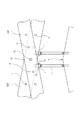
以下に、本発明を図面を参照しつつ説明する。図1は、本発明の第一実施形態に係る屋根作業用命綱取り付け装置が屋根に設置された状態を示す斜視図である。図1に示すように、切妻屋根のほぼ全面に亘って屋根作業用命綱取り付け装置が設置されている。この屋根作業用命綱取り付け装置は、傾斜した切妻屋根の棟部mに略沿って固定される複数のアンカー部材1と、アンカー部材1と連結し、屋根の棟部mから軒先sにむかって、屋根の傾斜に沿って棟部mと直角の方向に且つ互いに平行に設けられる複数本の梁棒2と、隣り合った梁棒2相互間を架橋する複数本のつなぎ棒3と、屋根上面に載置され梁棒2を支持する複数の脚体4と、を有する。梁棒2はC型チャンネル材または角パイプ材等から成り、つなぎ棒3はL字アングル材から成る。
The present invention will be described below with reference to the drawings. FIG. 1 is a perspective view showing a state in which a roof work lifeline attachment device according to a first embodiment of the present invention is installed on a roof. As shown in FIG. 1, a roof work lifeline attaching device is installed over almost the entire surface of the gable roof. This lifeline attachment device for roof work is connected to a plurality of
図1に示すように、梁棒2は屋根の棟部mと直角方向に設置される一方、隣り合った梁棒2間を架橋するつなぎ棒3は棟部mと平行な方向に設置されており、梁棒2とつなぎ棒3とで碁盤格子状の構造体を形成している。そして、この構造体は、梁棒2を支持する複数の脚体4により、屋根上面よりも上方の位置で固定されている。作業者は、作業位置に近い梁棒2又はつなぎ棒3に命綱を取り付けて安全を確保する。
As shown in FIG. 1, the
また、この屋根作業用命綱取り付け装置は、切妻屋根の棟部mを挟んだ2つの傾斜面のそれぞれにおいて同様の構成を備える装置とされている。そして、棟部mを挟んだ2つの傾斜面のそれぞれに設けた安全装置は、棟部mの上方に位置する梁棒2の棟連結部10において互いに連結されている。このようにすると、棟部mを挟んだ2つの傾斜面に設けられた装置相互間で重量的に釣り合い(バランス)がとれるので、装置をより一層安定的に設置できる。このように、装置が棟部mから2方向に傾斜する屋根両面に設けられ、且つ、棟部m近傍においてこれら屋根両面にそれぞれ設けられた装置同士が梁棒2等により連結されている場合には、前記釣り合いによりアンカー部材1が無くても装置が安定する。そして、本実施形態のように、屋根両面に亘って設けられた装置が棟部mを通る鉛直面に対して互いに対称である場合には、釣り合いが完全となるのでより好ましい。
Further, the roof work lifeline attaching apparatus is an apparatus having a similar configuration on each of two inclined surfaces sandwiching the ridge m of the gable roof. And the safety device provided in each of two inclined surfaces on both sides of the ridge part m is mutually connected in the
梁棒2の下部であって屋根の軒先s近傍には、梁棒2に固定される柵体5が軒先と略平行に設けられている。この柵体5は、枠体にメッキ金網が張られた構造のものであり、略鉛直方向に立設している。また、軒先sには、軒先から落下する物体を受け止める軒先養生籠6が設けられている。さらに、屋根の妻側端部即ちケラバの近傍には、屋根の妻側から落下する物体を受け止める妻部養生籠7が設けられている。
A
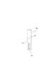
図2は、この屋根作業用命綱取り付け装置を屋根の妻側から見た側面図である。この図2では、分かりやすくするために妻部養生籠7の記載を省略している。梁棒2は、複数の梁棒ユニット2aを、梁棒ジョイント部11において棒状に連結することにより構成されている。脚体4は、屋根上面に載置されるとともに、梁棒2に沿って等間隔に設けられて梁棒2を支持している。一本の梁棒ユニット2a当たり一本の脚体4が設けられている。
FIG. 2 is a side view of the roof work lifeline mounting apparatus as viewed from the wife side of the roof. In FIG. 2, the illustration of the wife
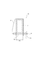
図3は、この屋根作業用命綱取り付け装置の棟部m付近の拡大断面図である。アンカー部材1は例えば直径16mm程度のボルトであり、屋根の棟部m付近に打ち込まれている。アンカー部材1の上部において梁棒2とアンカー部材1とが、くさび状の勾配座金15を介してナットnで締め付けられて互いに連結している。一本の梁棒2につき一本のアンカー部材1が連結している。
FIG. 3 is an enlarged cross-sectional view of the roof work lifeline mounting device in the vicinity of the ridge m. The
図4は、梁棒2を構成する梁棒ユニット2aの平面図であり、図5は、梁棒ユニット2a同士が連結する梁棒ジョイント部11の拡大平面図である。また、図6はつなぎ棒3の平面図であり、図7は梁棒2とつなぎ棒3との連結部分付近の拡大図である。図4(a)に示す梁棒ユニット2aは標準タイプの梁棒ユニット2aであるが、梁棒ユニット2aの一端には、板状のジョイント部材12が設けられている。なお、図4(b)は、梁棒ユニット2aのうち最も軒先に近い位置で用いられる軒先専用梁棒ユニット2a1であり、図4(c)は棟部専用梁棒ユニット2a3であるが、これらについては後述する。
FIG. 4 is a plan view of the
このジョイント部材12は、略長方形の板状部材であり、その半分が梁棒ユニット2aの一端に溶接やボルト等で固定されるとともに、残り半分は、梁棒ユニット2aの端部からその長手方向に沿って突出している。そして、図4(a)に示すように、この突出部分はジョイント用穴13を2つ有するとともに、梁棒ユニット2a本体の他端には、このジョイント用穴13に対応した本体ジョイント用穴14が2つ設けられている。そして、梁棒ユニット2a同士を連結する際には、一の梁棒ユニット2aの一端のジョイント部材12に設けられたジョイント用穴13と、他の梁棒ユニット2aの他端に設けられた本体ジョイント用穴14とを重ね合わせた上で、ボルトとナットにより両者を連結している。なお、ジョイント部材12は、全体が単一の板状であってもよく、あるいは部材の長手方向中央で折れ曲がる蝶番構造とされていてもよい。
The
図6に示すように、つなぎ棒3はL字アングル材から成り、且つその一の外面の両端付近にはボルト状のねじ山を有するボルト状突起3aが突設されている。一方、梁棒ユニット2aには、そのジョイント部材12寄りの位置に、ボルト状突起3aを挿入するための第一つなぎ受け孔2bが設けられている(図4及び図7参照)。さらに、図4及び図7に示すように、この梁棒ユニット2aにおいて、この第一つなぎ受け孔2bに隣接した位置には、短いL字アングル材であるL字アングル小片2cが溶接されており、このL字アングル小片2cには、ボルト状突起3aを挿入するための第二つなぎ受け孔2dが設けられている。そして、近接する2つのつなぎ受け孔である第一つなぎ受け孔2bと第二つなぎ受け孔2dとは、梁棒ユニット2aの長手方向と直角な方向に並列するとともに略同一平面上に位置している(図7参照)。
As shown in FIG. 6, the connecting
つなぎ棒3により隣り合った梁棒2間を架橋する構造は次の通りである。即ち、図7に示すように、つなぎ棒3が有する二つのボルト状突起3aのうち一方側のボルト状突起3aが、梁棒2の第一つなぎ受け孔2bに挿入され、且つ、これとは別のつなぎ棒3の他方側のボルト状突起3aが、同じ梁棒2に設けられ当該第一つなぎ受け孔2bと隣り合った第二つなぎ受け孔2dに挿入されている。そして、単一のつなぎ棒3の両端付近に設けられた二つのボルト状突起3aは、その一方側が一の梁棒2の第一つなぎ受け孔2bに挿入され、その他方側が、隣接する他の梁棒2の第二つなぎ受け孔2dに挿入されている。このつなぎ棒3による架橋が、棟部mと平行な方向に連続しているので、本実施形態に係る屋根作業用命綱取り付け装置では、図1に示すようにつなぎ棒3が連続した長い棒のように見え、梁棒2とつなぎ棒3とで碁盤格子状の構造体を構成している。
The structure in which the
ボルト状突起3aはボルト状のねじ山を有し、かつボルト状突起3aにはナット(図示省略)がねじ結合している。そして、梁棒2とつなぎ棒3とがこれらボルト状突起3aとナット(図示省略)によりねじ止めされている。このようにねじ止めすると、つなぎ棒3を梁棒2に確実に固定できるので好ましい。
The bolt-shaped
このように、屋根の上部から下部にかけて設けられた梁棒2は、その上部においてアンカー部材1と連結されており、さらに、一の梁棒ユニット2a当たり一本の脚体4で支持されているので、屋根上で極めて安定的に固定される。さらに、隣り合った梁棒2相互間はつなぎ棒3により架橋されているので、梁棒2とつなぎ棒3により強固な構造体を形成し、高い安全性が確保される。
Thus, the
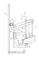
図8は、脚体4付近の側面図であり、図9は、脚体4の下部付近の側面図である。また、脚体4に関し、図7の下部には、脚体4の上部即ち脚体4と梁棒2との結合部分が記載されている。梁棒2には、梁棒ユニット2a一本当たり1カ所に脚取付用孔2eが設けられている(図4参照)。一方、脚体4の本体部4c(図7、図8参照)は角パイプ材より成るが、この本体部4cの上部には脚体プレート43が溶接されている(図7参照)。この脚体プレート43は、その一部が脚体4の本体部4cよりも上方に突出しており、且つ、角パイプ材の本体部4cの外周平面4面のうち対向する2面の上部に、当該平面と面接触させつつ溶接されている。その結果、溶接された2枚の脚体プレート43は、脚体4の本体部4cから突出した部分において、隙間を介して互いに対向する形となる。この隙間に梁棒2のC型チャンネル材を挟み込み、ボルトbで締結ことにより、脚体4が梁棒2に固定されている(図7参照)。
FIG. 8 is a side view of the vicinity of the
このボルトbを挿通すべく、脚体4の脚体プレート43には梁棒取付孔4aが設けられているが、これは上下方向(脚体4の長手方向)に長いルーズホールとされている(図8参照)。そして、ボルトbが脚体プレート43の梁棒取付孔4aと梁棒2の脚取付用孔2eとを貫通している。
In order to insert the bolt b, the
また、脚体4の最下部には、脚安定用部材4bが設けられている。脚安定用部材4bは、図8及び図9に示すように、上方から下方に向かって徐々に拡幅する2枚の台形プレート40と、これら2枚の台形プレート40の底辺相互間をつないで延在する底面プレート41と、この底面プレート41の外面に貼り付けられたゴムシート42から成る。そして、このゴムシート42が屋根上面と面接触している。2枚の台形プレート40は、角パイプより成る本体部4cの両面(棟と平行に対向する両面)の外側に、当該角パイプを挟んで対向して設けられ、これらをボルトbが貫通することにより、脚安定用部材4bは脚体4に固定されている。このボルトbを軸として、脚体4の本体部4cと脚安定用部材4bとは相対回転が可能であるため、脚体4の本体部4cに対する脚安定用部材4bの取付角度は可変である。よって、脚安定用部材4bの接地面であるゴムシート42が、屋根上面に沿うように角度調整することが可能となっている。この角度調節により、脚安定用部材4bの底面(即ちゴムシート42)を屋根上面と面接触させており、よって脚体4は屋根上面に安定的に載置されている。
A
前述のように、脚体4の梁棒取付孔4aはルーズホールとされている。即ち、梁棒取付孔4aの孔幅は、上下方向(脚体4の長手方向)に長くされており、この上下方向で固定位置が任意に調整できるようにされている。したがって、ボルトbの位置が梁棒取付孔4aの下側になるように脚体4を上方に移動させて、脚体4と屋根上面とを離間させることが可能となる。一の脚体4を上方に移動して浮かせた場合でも、他の脚体4が梁棒2を支持しているので、装置全体の安定性には影響がない。
As described above, the beam
このように、脚体4は、他の脚体4を屋根上面に載置した状態で個別的に屋根上面と離間しうる離間機構を有している。よって、屋根作業において脚体4が障害となる場合には、障害となる当該脚体4を屋根上面から離間させればよいので、屋根作業での作業性が極めて高くなる。例えば屋根材を葺く場合、脚体4を屋根上面から離間させることができなければその位置には屋根材を葺くことができず、作業が事実上不可能となる。しかし、この離間機構により、屋根の全面に屋根材を葺くことができる。したがってこの安全装置は、屋根葺き作業用として極めて好適に用いられる。
Thus, the
図10は、柵体5の正面図であり、図11は、柵体5と梁棒2との連結部分(図10の円内)を示す拡大正面図である。柵体5は、柵体ユニット5aの集合体であり、隣り合う梁棒2間に一の柵体ユニット5aが設けられ且つこれら柵体ユニット5aが軒先sと平行に並列することにより柵体5が形成されている。
FIG. 10 is a front view of the
柵体ユニット5aは、L字アングル材から成る枠体51と、この枠体51内に設けられたメッキ金網52とを有する。このように柵体ユニット5aは、いわゆる養生金網と似た構造のものであるが、枠体51の下辺両端に柵体脚部53を有する点で通常の養生金網と異なる。この柵体脚部53は、枠体51と一体構造を成しており、この柵体脚部53と梁棒2とが連結することにより、柵体ユニット5aは梁棒2に固定されている。図10に示すように、枠体51の下辺の両端付近の2カ所には、当該下辺の外側底面から下方に向かって延びる柵体脚部53が突設され、また図11に示すように、この柵体脚部53が断面コの字型でボルト穴を有する締付座金16を介して梁棒2であるC型チャンネル材とボルトにより固定されている。一の柵体脚部53に対して二つの締付座金16が柵体脚部53を挟み込むように設けられている。なお、梁棒2はC型チャンネル材であるので、その長方形断面の長辺側の一の面においては中央部分が欠落しているが、この欠落部分を補ってボルトbによる固定を可能とするために補助プレート17を介在させている(図11参照)。
The
図12は、柵体ユニット5aの柵体脚部53付近の側面図である。柵体脚部53は角パイプから成るが、かかる角パイプを構成する4面のうち、柵体5の面(メッキ金網52による面)と平行な方向に対向する2面において細長いスリット状の切り欠き54を有する(図12参照)。切り欠き54は、柵体脚部53の下端からその長手方向に沿って所定位置まで設けられている。図11に示すように、この切り欠き54の外側に前述の締付座金16を被せて、これらの部材と梁棒2のC型チャンネル材とを、貫通するボルトb及びナットnで締め込むことにより、柵体ユニット5aは梁棒2に固定されている。
FIG. 12 is a side view of the vicinity of the fence
なお、柵体ユニット5aを設置する前に、あらかじめ梁棒2に前記締付座金16、ボルトb及びナットnを取り付けた状態としておく。つまり、図4(b)に示すように、梁棒ユニット2aのうち軒先専用に用いられる軒先専用梁棒ユニット2a1には、その軒先側近傍に、締付座金16、ボルトb及びナットnから構成される柵体取付クランプ20があらかじめ取り付けられている。そして、柵体ユニット5aを設置する際には、柵体ユニット5aを柵体取付クランプ20の上から差し込むようにして切り欠き54にボルトbを挿通させた後にボルトbとナットnで締めて固定する。このように、柵体ユニット5aの柵体脚部53に切り欠き54を設けることにより、屋根上での柵体ユニット5aの取り付け作業が簡略化され、柵体ユニット5aの取り付けが極めて容易となる。
In addition, before installing the
柵体ユニット5aと梁棒2とは、ボルトbを締め付けることにより固定されているため、柵体ユニット5aと梁棒2とのなす角度は、ボルトbを軸として当該軸回りに角度調節が可能となり、屋根の傾斜角度に応じて柵体5を鉛直に固定することができる。また、この角度調節の際、柵体脚部53に対するボルトbの位置は多少上下に移動することがあるが、前述の切り欠き54によりボルトの貫通位置を上下方向で調整できるので、角度調節が円滑に行われる。
Since the
なお、柵体ユニット5aは軒先sに沿って複数並列しているが、図10及び図13に示すように、隣り合った柵体ユニット5a同士は、その枠体51の上面に設けられた止め金27により連結している。図13は、この止め金27付近を上方から見た平面図である。止め金27は略長方形の板材であるが、その長手方向一端寄りに回転穴27bを有し、その長手方向他端寄りには、当該長方形の長辺側から短辺と平行な向きに所定位置まで延びる切り欠き状のボルト横入れ部27aを有する。止め金27は、回転穴27bを挿通するボルトbにより回転自在に軸着されている。そして、一の柵体ユニット5aの一端側に回動自在に軸着された止め金27をボルトb回りに回転させて、隣接する他の柵体ユニット5aの他端側に取り付けられたボルトbをボルト横入れ部27a内に呼び込んではめ入れた後、各ボルトbを締めて固定する。このように柵体ユニット5a同士を連結する止め金27を設けることにより、柵体ユニット5aの固定がさらに強固となり安全性が更に高まる。
In addition, although the
以上に述べたように、柵体5は、安定的に設置された梁棒2上に固定されているので、柵体5も安定的に固定されることとなり、作業者の高い安全性が確保される。また、柵体5と梁棒2との成す角度を変更できるので、様々な傾斜角度を有する屋根に対応して柵体5を鉛直に立設して固定できる。さらに、柵体5を設けることにより、作業者に視覚的な安心感を与えるとともに、作業者の転落を防止する。また、柵体5の枠体51の上縁部は手摺として作業者が握ることができ、安全性が一層高まる。
As described above, since the
図14は、軒先s近傍に設置された軒先養生籠6の正面図であり、図15は、この軒先養生籠6が設置された軒先s近傍の拡大断面図である。図14及び図15に示すように、軒先養生籠6は、金属フレーム61と、この金属フレーム61内に張設された養生金網62と、金属フレーム61の上部から上方に延び且つ上端部でU字状に湾曲する吊り下げフック63とを有する。図14に示すように、吊り下げフック63は、一の軒先養生籠6について合計3つが設けられ、その設置位置は、軒先養生籠6の両端部分と中央部分である。軒先養生籠6が軒先sと平行に並列することにより、軒先s全体が軒先養生籠6で覆われている(図1参照)。
FIG. 14 is a front view of the eaves
図15に示すように、金属フレーム61は、上部に吊り下げフック63が固定されかつ下向きに延びる外フレーム61aと、外フレーム61aの最下端部から略水平方向に延びる底フレーム61bと、底フレーム61bの最内端部から上向きに延びる内フレーム61cよりなり、これらのフレーム内には養生金網62が設けられている。このように、断面3面構造の軒先養生籠6とすることにより、軒先sから落下する物体を確実に受け止めることができる。
As shown in FIG. 15, the
図15に示すように、軒先養生籠6と、軒先sに設けられた軒樋18との間には隙間kが設けられている。このような隙間kを確保すべく、軒先養生籠6の各部寸法や軒先吊棒19の位置が調整されている。かかる隙間kを設けているので、軒先養生籠6を設置した状態で、軒樋18を交換する作業や軒樋18を設置する作業を行うことができるとともに、当該軒樋18を設置又は交換する作業において軒先sから落下する物体を確実に受け止めることができる。
As shown in FIG. 15, a gap k is provided between the eaves-
軒先養生籠6は、梁棒2の下部相互間を軒先sに沿って架橋する丸パイプから成る軒先吊棒19に吊り下げられている(図15参照)。軒先吊棒19は、隣り合った梁棒2間を架橋するように設置され、軒先sに沿って複数の軒先吊棒19が略同一軸線上に縦列している。図4(b)に示すように、軒先専用梁棒ユニット2a1の軒先側端部上面には、断面コの字型の軒先吊棒受21が溶接固定されている。軒先吊棒受21の断面コの字は軒先と反対の方向即ち棟の方向に開口しているので(図15参照)、軒先吊棒受21は、屋根の傾斜(即ち梁棒2の傾斜)に沿って上向きに傾斜して開口することとなる。そして、軒先吊棒19の外径は、軒先吊棒受21の開口幅と略同一とされている。よって、軒先吊棒受21の開口側から軒先吊棒19を挿入することにより、軒先吊棒19が軒先吊棒受21によって確実に固定される。
The eaves-
図16(a)は、軒先吊棒19が軒先sと平行な方向に並列する状態を示す正面図である。この図に示すように、軒先吊棒19には、その両端付近に、軒先吊棒19の軸方向の滑りを防止するフランジ状の滑り止め鍔19aが設けられている。この滑り止め鍔19aを軒先吊棒19の両端よりもわずかに軸方向中央寄りの位置に設けることにより、滑り止め鍔19aから軒先吊棒19の両端までの範囲に棒受挿入部19bが確保されている。この棒受挿入部19bの軸方向長さは、軒先専用梁棒ユニット2a1のC型チャンネル材の断面の長方形における短辺の長さの略半分の長さとされている。よって、図16(a)に示すように、一つの軒先吊棒受21(図16(a)において破線で示す)に、隣り合う別個の軒先吊棒19の2つの棒受挿入部19bが挿入されている。さらに、滑り止め鍔19aにより軒先吊棒19の軸方向位置が位置決めされる。なお、図16(b)に示すように、滑り止め鍔19aは矩形の板状部材である。
FIG. 16A is a front view showing a state where the
以上のような構成とすることにより、軒先吊棒19の設置が極めて容易となり、且つ、確実に軒先吊棒19を梁棒2に固定することができる。即ち、軒先吊棒19を設置するには、軒先吊棒受21に棒受挿入部19bを挿入するだけでよいので、その設置作業は極めて簡便である。しかも、軒先吊棒受21に設けた軸方向滑り防止機構である滑り止め鍔19aにより、軒先吊棒19が軒先吊棒受21から外れることがない。また、軒先吊棒19は、屋根上に安定的に設置された梁棒2に設置しているため、軒先吊棒19自体も安定して設置される。その結果、この軒先吊棒19に吊り下げられる軒先養生籠6も安定的に設置されている。
By setting it as the above structures, installation of the
この軒先吊棒19に軒先養生籠6が吊り下げられている。即ち、図15に示すように、軒先養生籠6の吊り下げフック63を軒先吊棒19に掛けることにより、軒先養生籠6を軒先吊棒19に吊り下げている。吊り下げフック63は帯状の金属板材であり、軒先吊棒19と接する湾曲部の曲率半径は、軒先吊棒19の外径とほぼ等しくしている。しかも、吊り下げフック63は、単に金属棒や針金を曲げた様なフックではなく、所定幅を有する帯状の板状部材であって、吊り下げフック63の湾曲部内周面が形成する凹部に軒先吊棒19が当接している。したがって、吊り下げフック63は、遊びやガタツキが少ない状態で軒先吊棒19に吊り下げられている。また、吊り下げフック63の湾曲部から末端までに至る折り返し部63aの長さは、軒先吊棒19の直径よりも充分に(2倍程度以上に)長くされている。したがって、軒先養生籠6は多少の振動や衝撃を受けても軒先吊棒19から外れない。
An eaves-
また、軒先吊棒19は軒先sと略平行に設けられているので、軒先養生籠6に複数設けられた吊り下げフック63を軒先吊棒19に吊り下げるだけで、軒先養生籠6は軒先sに沿って設置されることとなる。また、軒先吊棒19は軒先sに沿って延在しており、この軒先吊棒19上において軒先養生籠6の吊り下げ位置(吊り下げフック63の設置位置)は特に限定されていない。したがって、軒先養生籠6は、吊り下げ位置の自由度が非常に高くなっている。よって、軒先養生籠6を軒先吊棒19に吊り下げる場合、軒先吊棒19と軒先養生籠6との相対的位置関係を正確に調整する必要が無い。また、軒先吊棒19上における吊り下げフック63の位置が特に限定されないため、吊り下げフック63の設置間隔や設置個数の設定自由度も高くなる。このように、軒先吊棒19を軒先sと略平行に設けることにより、軒先養生籠6を極めて容易に設置できる。
Further, since the
このように、軒先養生籠6は、軒先吊棒19に吊り下げるだけで設置できるので、その設置が極めて容易である。しかも、軒先養生籠6自体は極めて小型で且つ軽量とすることができる。よって、軒先養生籠6の取り扱いや搬送が極めて容易となる。また、軒先吊棒19は、安定的に固定された梁棒2に設置されているので、この軒先吊棒19及び当該吊棒19に吊り下げられた軒先養生籠6は安定的に設置され、且つ落下する恐れがない。
As described above, the eaves-
さらに、本実施形態では、屋根の妻側から落下する物体を受け止める妻部養生籠7を設けている。この妻部養生籠7の構造及び妻部養生籠7を固定する構造は、軒先養生籠6のそれと類似している。図17は、妻部tの近傍に設置された妻部養生籠7の正面図であり、図18は、この妻部養生籠7が設置された妻部t近傍の断面図である。
Furthermore, in this embodiment, the wife
妻部養生籠7自体の構造は、前述の軒先養生籠6と同様であるので説明を省略する。ただし、図17に示すように、軒先養生籠6と異なり、妻籠金属フレーム71の形状は長方形でなく平行四辺形となっており、屋根の妻部tに沿って設置するのに適した形状とされている。
Since the structure of the
図18に示すように、妻部養生籠7は、屋根の最も妻側に位置する梁棒2に妻部tと平行に設けられた妻部吊棒22に吊り下げられている。最も妻側に位置する梁棒2には、その妻側面から妻側に突設された妻側突起23が溶接されている。即ち、梁棒2を構成する梁棒ユニット2aのうち、最も妻側に位置する梁棒ユニット2aは、妻側突起23が溶接された妻部専用梁棒ユニット2a2とされている。この妻側突起23はL字アングル材であり、その一面には、妻側突起23の突出方向に向かって長いルーズホールとされた妻部吊棒挿通孔24が設けられており、この妻部吊棒挿通孔24に妻部吊棒22を挿通することによって妻部吊棒22が設置されている。そして、この妻部吊棒22に妻部養生籠7が吊り下げられている。妻部吊棒挿通孔24がルーズホールとされているので、屋根の妻部形状に対応させて妻部養生籠7の位置を調整することが可能となる。
As shown in FIG. 18, the wife
図19は、別々の妻部吊棒22同士が連結する連結部の拡大図である。図19に示すように、妻部吊棒22の一端には、当該妻部吊棒22の外径と略同一の内径を有する継ぎパイプ25が溶接固定されており、この継ぎパイプ25に別の妻部吊棒22の他端を差し込むことによって、複数の妻部吊棒22が連結している。このようにして複数本連結した妻部吊棒22が屋根の妻部tと平行に設けられている。なお、図示を省略するが、妻部吊棒22は、前述の軒先吊棒19と同様にフランジ状の滑り止め鍔を有しており、横滑りを防止している。この滑り止め鍔は、前述のつなぎ棒3の妻側末端部分と当接する位置に設けており、妻部吊棒22の軸方向の滑りを防止する。
FIG. 19 is an enlarged view of a connecting portion where separate
以上のような構成によれば、妻部養生籠7は、妻部吊棒22に吊り下げるだけで設置できるので、妻部養生籠7が極めて容易に設置できるとともに、妻部養生籠7自体を極めて小型化且つ軽量化できる。また、妻部吊棒22は、安定的に固定された梁棒に設置されているので、この妻部吊棒22及び当該吊棒22に吊り下げられた妻部養生籠7は安定的に設置され、また落下する恐れがない。
According to the configuration as described above, since the wife
また、妻部吊棒22が妻部tと略平行に設けられていることにより、前述の軒先吊棒19と同様の利点を有する。即ち、妻部養生籠7を妻部吊棒22に吊り下げるだけで、妻部養生籠7は妻部tに沿って設置されることとなる。また、妻部吊棒22は妻部tに沿って延在しており、この妻部吊棒22上において妻部養生籠7の吊り下げ位置は特に限定されていない。したがって、妻部養生籠7は、吊り下げ位置の自由度が非常に高くなっている。よって、妻部養生籠7を妻部吊棒22に吊り下げる場合、妻部吊棒22と妻部養生籠7との相対的位置関係を正確に調整する必要が無い。このように、妻部吊棒22を妻部tと略平行に設けることにより、妻部養生籠7を極めて容易に設置できる。
Further, since the end
図4(c)、図2及び図3に示すように、梁棒2の上側端部を構成し、最も上側に位置する棟部専用梁棒ユニット2a3は、その長手方向に沿って複数のボルト穴hを備えている。図3に示すように、本実施形態では、切妻屋根の一の面に設けられた梁棒2と、切妻屋根の他の面に設けられた梁棒2とが、棟連結部10において棟部連結ボルト26により連結している。このように、棟部から2方向に傾斜する両面に設けられた梁棒2同士を結合することにより両者がバランスし、装置の固定がより安定することは前述の通りであるが、棟部専用梁棒ユニット2a3はその長手方向に沿って複数のボルト穴hを有しており、この複数のボルト穴hにより、棟部連結ボルト26による連結位置を調整できる。隣り合う複数のボルト穴h間の間隔ht(図4(c)参照)は10cm程度以下としておけば位置調整が容易となる。このようにすると、屋根の大きさに対応して棟部専用梁棒ユニット2a3の長さを調整する必要が無くなる。しかも、ボルト穴hにボルトを挿通して連結するから、極めて強固かつ確実に連結することができる。したがって、梁棒2の固定がより一層強固となり、ひいては屋根作業用命綱取り付け装置全体が極めて安定的に固定される。なお、本実施形態では、複数のボルト穴hを棟部専用梁棒ユニット2a3同士の連結に利用したが、アンカー部材1との連結に利用してもよい。
As shown in FIG. 4C, FIG. 2 and FIG. 3, the ridge part exclusive beam bar unit 2a3 which constitutes the upper end portion of the
本実施形態に係る屋根作業用命綱取り付け装置は、装置全体としては屋根のほぼ全面を覆うことのできる大きさに組み立てられているが、装置を構成する全ての部材はその長さが2500mm以下とされ、更には2100mm以下とされている。即ち、梁棒2を構成する梁棒ユニット2aの長さLr(図4参照)は1500mm〜2090mmとされ、つなぎ棒3の長さLt(図6参照)は1990mmとされ、柵体5の長辺の長さLs(図10参照)は1980mmとされている。さらに、軒先養生籠6の長手方向長さLn(図14参照)は1930mmとされ、軒先吊棒19の長さLb(図16(a)参照)は1990mmとされている。更には、妻部養生籠7の長手方向長さLy(図17参照)は2000mmとされ、妻部吊棒22の長さ(図示しない)は2050mm(継ぎパイプ25を含む)とされている。その他の部材も2100mm以下とされている。
The lifeline attaching device for roof work according to the present embodiment is assembled in a size that can cover almost the entire surface of the roof as a whole device, but all members constituting the device have a length of 2500 mm or less. Furthermore, it is set to 2100 mm or less. That is, the length Lr (see FIG. 4) of the
ここで、汎用のエレベーターの内部高さは約2500mmであり、このエレベーターの内部の幅や奥行きは2500mmより小さい。よって、装置を構成する全ての部材の長さが2500mm以下であると、汎用のエレベーターに全ての部材を積み込むことができ、部材を屋根まで搬送することが極めて容易となる。さらには本実施形態のように2100mm以下であると、エレベーターへの積み込みがより一層円滑となり、屋根上での取り扱いも容易となるので好ましい。 Here, the internal height of the general-purpose elevator is about 2500 mm, and the internal width and depth of the elevator are smaller than 2500 mm. Therefore, when the length of all the members constituting the apparatus is 2500 mm or less, all the members can be loaded into a general-purpose elevator, and it becomes extremely easy to transport the members to the roof. Furthermore, it is preferable that it is 2100 mm or less as in the present embodiment, because loading into the elevator becomes even smoother and handling on the roof becomes easier.
ところで、つなぎ棒3の長さLtの長さを2500mm以下、更には2100mm以下とすることができたのは、隣り合った梁棒2相互間の、軒先と平行な方向における間隔Pr(図7参照)を2500mm以下、更には2100mm以下としたことによる。即ち、梁棒2の設置間隔Prを2500mm以下、更には2100mm以下としたので、隣り合う梁棒2相互間を架橋するつなぎ棒3の長さも短くできたのである。そして、梁棒2相互間をつなぎ棒3で架橋した結果、図1に示すような碁盤格子状の屋根作業用命綱取り付け装置としている。
Incidentally, the length Lt of the connecting
このように、本実施形態では、隣り合った梁棒2相互間の、軒先と平行な方向における間隔Prを2500mm以下とし、さらには2100mm以下としたので、隣り合った梁棒2相互間を架橋するつなぎ棒3の長さLtを2500mm以下、さらには2100mm以下とすることができた。また、隣り合うつなぎ棒3相互間の妻部tと平行な方向における間隔Pt(図2参照)も2500mm以下、更には2100mm以下とした。その結果、図1に示す碁盤格子状の屋根作業用命綱取り付け装置は、隣り合い且つ平行な2本の梁棒2と、隣り合い且つ平行な2本のつなぎ棒3とにより構成される矩形構造を単位とする集合体であって、この矩形単位の1辺が2500mm以下、更には2100mm以下とされている。よって、作業者は、屋根上のいずれの地点においても安全装置が身近に存在することとなる。したがって、命綱の長さが非常に短くなり、命綱が長い場合と比較して作業者の体勢が安定する他、命綱に足を取られる可能性が少なくため、作業性や安全性が向上する。また、作業者が作業中に体勢を崩した場合等でも、身近に存在する梁棒2又はつなぎ棒3に直ちに掴まることができるので、作業の安全性が極めて高くなる。
As described above, in this embodiment, the distance Pr between the
本発明において、各部材を構成する材質等は特に限定しない。ただし、建築資材として用いられる汎用の資材を用いるとコスト面で有利となり好ましい。また、各部材に求められる強度や剛性を考慮しつつ、軽量化にも配慮した材料とすることが好ましい。例えば、比較的高い強度と剛性が要求される梁棒2を構成する梁棒ユニット2aとしては、汎用のC型チャンネル材や角パイプ等を用いることができ、例えば、断面寸法が100mm×50mm×20mm程度で肉厚が2.3mm程度のリップ溝型鋼を使用しうる。また、特に軒先専用梁棒ユニット2a1は、柵体5や軒先養生籠6を取り付けるので、他の梁棒ユニット2aよりも剛性を高めるのが好ましく、例えば断面寸法は100mm×50mm×20mmで同一としつつ肉厚を3.2mm程度と厚めにした鋼を使用しうる。また、つなぎ棒3としては、例えば汎用のL字アングル材を使用することができ、例えば断面寸法が50mm×50mm程度で肉厚が5mm程度のものを使用しうる。
In the present invention, the material constituting each member is not particularly limited. However, it is preferable to use a general-purpose material used as a building material because it is advantageous in terms of cost. Moreover, it is preferable to use a material that considers weight reduction while considering strength and rigidity required for each member. For example, as the
一方、軒先養生籠6や妻部養生籠7は、梁棒2やつなぎ棒3ほど大きな強度や剛性を必要としないので、軽量化を重視した材料を用いることができる。例えば、軒先養生籠6の金属フレーム61や、妻部養生籠7の妻籠金属フレーム71は、アルミ又はアルミ合金を使用するのが好ましく、例えば断面寸法が20mm×20mm程度のアルミ合金製角パイプを使用することができる。また、吊り下げフック63には厚さ2mm、幅20mm程度のステンレス板を使用しうる。その他、梁棒2を支持するアンカー部材1としては、直径16mm程度のボルトを使用でき、また脚体4の本体部4cとしては断面寸法50mm×50mm程度で厚みが2.3mm程度の角パイプを使用することができる。
On the other hand, since the eaves-
脚体4の離間機構は、前記実施形態のような構成に限られない。例えば、蝶番等により脚体4を折りたたみ可能としてもよい。この場合、不必要に折りたたまれることを防止する安全機構を更に設けるのが好ましい。また、脚体4を折りたたみ可能とする場合、隣り合った脚体4間で折りたたまれる方向を互い違いにしておくのが好ましい。ここで、隣り合った脚体4とは、同一の梁棒2を支持し屋根の上下方向に隣り合った脚体4でも良く、屋根の水平方向において隣り合った脚体4でも良い。このように隣り合った脚体4間で折りたたまれる方向を互い違いにしておくことにより、全ての脚体4が一方向に倒れてしまうことが防止されるので安全性が高まる。このような折りたたみ式の脚体4とすると、脚体4を離間させる作業が比較的容易となる点においては好ましいが、脚体4の安定性や、脚体4による梁棒2の支持の確実性、さらには製造コストをも考慮すると、脚体4は折りたたみ構造ではなく、前述のようなルーズホールを有する構造とするのが好ましい。
The separation mechanism of the
前述の実施形態においては、図8に示すように、脚体4の梁棒取付孔4aをルーズホールとすることにより、脚体4を屋根上面と離間しうる構成としているが、これに加え、又はこれに替えて、脚安定用部材4bを取り付けるべく台形プレート40及び/又は脚体4の本体部4cに設けられたボルト穴hをルーズホールにすることにより、脚安定用部材4bを脚体4の本体部4cに対して上下しうる構成としてもよい。このようにすると、脚安定用部材4bの上下動のみで脚体4を屋根上面から離間できるので作業性が向上する。また、前述の折りたたみ機構を採用する際には、脚安定用部材4bを浮かせることで折りたたみ作業が円滑に行われる。
In the above-described embodiment, as shown in FIG. 8, the
脚体4の離間機構に関し、屋根上面と離間した脚体との間の隙間距離は4cm以上、さらには5cm以上とするのが好ましい。この程度の隙間が確保できれば、シングル等の屋根材を容易に葺くことができる。
With regard to the separation mechanism of the
梁棒2と屋根上面との間の隙間距離は特に問わないが、100mm以上が好ましく、150mm以上がより好ましく、200mm以上が特に好ましい。この隙間距離が小さすぎると梁棒2あるいはつなぎ棒3が屋根葺き作業等の作業において障害となる場合があるからである。一方、この隙間距離が大きすぎると、脚体4が長くなり装置が不安定となる傾向となるので、500mm以下が好ましく、さらには400mm以下が好ましく、特に300mm以下が好ましい。
The gap distance between the
本発明は、前記実施形態のような切妻屋根に限られず、片流れ屋根、のこぎり屋根、越し屋根、M型屋根、腰折れ屋根、方型屋根、寄せ棟屋根、入り母屋屋根、しころ風屋根、半切妻屋根、から破風屋根、乗越し屋根、等あらゆる形状の傾斜屋根に適用できる。ここで、例えば片流れ屋根の場合、図20に示すように、建造物の棟部mから鉛直下方に向かって延在する垂直壁面にボルト穴hを有するアンカー部材1を固定し、このボルト穴hと棟部専用梁棒ユニット2a3のボルト穴hとにボルトbを挿通して締結することにより、アンカー部材1に梁棒ユニット2aとを連結させることができる。また、寄せ棟屋根の場合には、例えば、二本の梁棒2を束ね合わせた部材を当該寄せ棟屋根の寄せ棟棟部に沿って固定し、かかる2本の梁棒2のそれぞれが、各傾斜面上に設置される梁棒2やつなぎ棒3などと連結する構成としてもよい。
The present invention is not limited to the gable roof as in the above-described embodiment, but is a single-flow roof, a saw roof, a crossover roof, an M-shaped roof, a folded back roof, a square roof, a side roof, a main roof, a roller roof, a half It can be applied to all types of sloped roofs such as gable roofs, to windbreak roofs, overpass roofs. Here, for example, in the case of a single-flow roof, as shown in FIG. 20, an
本発明の屋根作業用命綱取り付け装置で複数のユニット部材を用いる場合、基本的には同一のユニット部材を単位としてこれを複数用いることとなる。しかし、屋根の大きさにより調整が必要な場合には、別途調整用ユニット部材を用いることができる。例えば、建造物の軒先sの長さが、軒先養生籠6の長手方向長さLn(図14参照)の整数倍でないような場合には、このLnよりも長手方向長さが短い調整用軒先養生籠を別途設けることができる。この点は、妻部養生籠7など他の部材に関しても同様である。
When a plurality of unit members are used in the roof work lifeline attaching device of the present invention, basically, the same unit member is used as a unit. However, if adjustment is necessary depending on the size of the roof, a separate adjustment unit member can be used. For example, in the case where the length of the eaves s of the building is not an integral multiple of the longitudinal length Ln (see FIG. 14) of the
前述の実施形態では、柵体5は枠体51とメッキ金網52を有する構成としたが、かかる構成に限定されない。例えば、メッキ金網52の部分が格子等であっても良く、また枠体51のみでメッキ金網52が無いようなものでも良い。また、柵体5の高さh5(図10参照)は特に問わないが、前述のような視覚的効果や安全効果を充分なものとするためには、500mm以上が好ましく、更には700mm以上がより好ましく、900mm以上が特に好ましい。なお、この高さh5が大きすぎると柵体5が大きくなり取り扱いや搬送がしにくくなるので、1500mm以下が好ましく、1200mm以下がより好ましい。
In the above-described embodiment, the
図15に示すように、軒先養生籠6は、軒樋18との間に隙間kを有しうる大きさとするのが好ましい。ここで、軒樋18の幅18wは、比較的大型の軒樋18でも180mm程度である。また、軒樋18の高さ18hも同様に180mm程度である。このことを考慮すると、軒先養生籠6の吊り下げ側面の高さ6hは500mm〜900mm程度が好ましく、600mm〜800mmがさらに好ましい。軒先養生籠6の奥行き6wは300mm〜800mmが好ましく、400mm〜700mmが更に好ましく、400mm〜600mmが特に好ましい。これらの値が大きすぎると、軒先養生籠6が大きくなりすぎて搬送上不便となる。これらの値が小さいと隙間kを充分確保できず軒樋18の取り付けや交換の作業をしにくくなる場合がある。なおこの場合、軒先専用梁棒ユニット2a1が軒先sよりも外側にはみ出している長さL2は200mm〜500mm程度とすると隙間kを確保しやすくなるので好ましい。隙間kの幅としては、50mm以上、さらには100mm以上確保できれば作業しやすいので好ましい。隙間kの幅が大きすぎる場合は軒先養生籠6が大きくなりすぎることとなるので、隙間kの幅は300mm以下、更には200mm以下が好ましい。
As shown in FIG. 15, it is preferable that the eaves-
なお、柵体5は、前述の実施形態のように、梁棒2に固定されるのが好ましいが、図11に示すように、梁棒2に直接的に取り付けられている場合のみならず、梁棒2と柵体5との間に、梁棒2に固定された他の部材が介在していてもよい。例えば、つなぎ棒3が、そのボルト状突起3aとこれにねじ結合するナットにより梁棒2にねじ止めされており、このつなぎ棒3に柵体5が固定されている場合でも、結局は柵体5が梁棒2に固定されていることになるので、柵体5が安定的に設置できて好ましい。
In addition, it is preferable that the
また、軒先養生籠6や妻部養生籠7を吊り下げるための軒先吊棒19や妻部吊棒22は、前記の実施形態の如く梁棒2に設置されているのが好ましい。梁棒2はアンカー部材1と連結し且つ脚体4に支持されて安定的に設置されているので、この梁棒2に軒先吊棒19や妻部吊棒22を設置すると、軒先吊棒19や妻部吊棒22も安定的に設置できるからである。
Moreover, it is preferable that the eaves
梁棒2とアンカー部材1とを連結する場合、前述の実施形態のように梁棒2と直接連結している場合に限られず(図3参照)、他の部材を介して連結されていてもよい。例えば、梁棒2とボルト締め固定されたつなぎ棒3にアンカー部材1が連結していてもよい。なお、アンカー部材1は、実施形態の如く一本の梁棒2について一つ設けると、梁棒2の固定を強固にしつつアンカー部材1の数を最小限にして建造物の損傷を抑制しうる点で好ましい。また前述のように棟部mを挟んだ屋根両面に装置を設けてアンカー部材1を設けない場合には、アンカー部材1による建造物の損傷がない点で好ましい。
The connection between the
図21〜図26は、本発明の第二実施形態に係る屋根作業用命綱取り付け装置を示す。図1〜図19に示す第一実施形態と装置の基本構成は同一であるので、第一実施形態との主たる相違点について説明する。 FIG. 21 to FIG. 26 show a lifeline attaching device for roof work according to a second embodiment of the present invention. Since the basic configuration of the apparatus and the first embodiment shown in FIGS. 1 to 19 are the same, the main differences from the first embodiment will be described.
第二実施形態においては、脚体4を屋根上面から離間させる離間機構が前述の第一実施形態と異なる。図21は、脚体4付近の側面図であるが、本第二実施形態における脚体4は、梁棒2を左右方向から挟み込みつつ対向する長方形の2枚の側面板80(図21においては、このうち1枚の(図面手前側の)側面板80のみ表記される)と、これら対向する2枚の側面板80間の屋根下側長辺同士の間に延び2枚の側面板80を連結する下側連結板81(図21において断面で示す)と、同じく対向する2枚の側面板80間の屋根上側長辺同士の間に延び2枚の側面板80を連結する上側連結板82(図21において断面で示す)とを有する。一方、2枚の側面板80には、その略長手方向に並列する2つの穴である上側貫通孔83及び下側貫通孔84が設けられている。一方、梁棒2にもこれら貫通孔83,84と対応する位置に貫通孔が設けられており、脚体4が立設した状態では、貫通孔83,84はそれぞれ2枚の側面板80及びその間に介在する梁棒2を貫通する貫通孔を構成する。そして、脚体4は、2つの貫通孔83,84のうちの何れか一つの貫通孔(ここでは、下側貫通孔84)に挿通された軸部材(図示省略)により梁棒2に対して回動可能に軸着されている。したがって脚体4は、下側貫通孔84の孔軸まわりに回動する。
In the second embodiment, the separation mechanism for separating the
この回動軸たる下側貫通孔84の孔軸と屋根上面yとの距離は、屋根下方向にいくにしたがって大きくなり、逆に、屋根上方向にいくにしたがって小さくなる。よって脚体4は、屋根上方向には屋根が邪魔となって容易には回動できないが、図21に矢印で示す屋根下方向には容易に回動できる。したがって屋根作業の際には、脚体4を屋根上側から屋根下方向に押すだけで容易に脚体4が屋根上面yから離間し、屋根材を葺く等の作業を円滑に進めることができる。
The distance between the hole axis of the lower through-
また、脚体4を離間させないときには、脚体4を立設した状態で上側貫通孔83と梁棒2とを貫通する軸体(後述する折れピン等)を挿入して、脚体4の回動を防止する。このようにすることで装置の安定性が高まる。
ここで、図21の脚体4において断面で示す下側連結板81と上側連結板82とを比較すると、上側連結板82は側面板80の下方から梁棒2に近い位置まで延在しているのに対し、下側連結板81は側面板80の下方寄りの一部分にのみ設けられている。よって、下側連結板81の上方であって対向する側面板80相互間には開口部85があり、脚体4が屋根下方向に回動する際には、この開口部85に梁棒2が入り込むこととなり、脚体4の屋根下方向への回動が許容されている。
一方、脚体4の屋根上側には前記開口部85のような開口部がなく、脚体4が屋根上方向に回動しようとすると上側連結板82の上縁部が梁棒2に当接して当該回動が阻止される。このように、脚体4の回動を屋根下方向のみに規制する規制手段を設けた場合には、屋根下方向に作用する重力等の影響で脚体4が屋根上方向に倒れうるような事態が万一発生したとしても、当該屋根上方向への脚体4の回動を阻止するので、装置の安全性、安定性が更に高まる。
なお、屋根下方向とは、棟部mから軒先sへと向かう方向のことであり、屋根上方向とは、逆に軒先sから棟部mへと向かう方向のことである。また、左右方向とは、屋根上面yと平行で且つ屋根上下方向と垂直な方向のことである。
Further, when the
Here, comparing the lower connecting
On the other hand, there is no opening such as the
The roof downward direction is a direction from the ridge m to the eaves s, and the roof upper direction is a direction from the eaves s to the ridge m. The left-right direction is a direction parallel to the roof upper surface y and perpendicular to the roof vertical direction.
図22は、第二実施形態に係るつなぎ棒86である。
このつなぎ棒86は伸縮可能とされている。即ちこのつなぎ棒86は、比較的太い角パイプである太角パイプ87の中空内部に、この太角パイプ87よりも一回り細い角パイプである細角パイプ88が挿入された構造となっており、この細角パイプ88を太角パイプ87に対して相対移動させつつ抜き差しすることにより伸縮可能とされている。また、かかる太角パイプ87と細角パイプ88との相対移動を防止してつなぎ棒86を一定長さで固定するための固定ねじ89が設けられている。
また、このつなぎ棒86の両端部には、梁棒2の上方から当該梁棒2を嵌め込むことができる嵌め込みジョイント部90が設けられている。
FIG. 22 shows a connecting rod 86 according to the second embodiment.
The connecting rod 86 can be expanded and contracted. That is, the connecting rod 86 has a structure in which a narrow-
Further, at both ends of the connecting rod 86, fitting
図23は、この嵌め込みジョイント部90及びこれに挿入される折れピン91の拡大断面図である。この嵌め込みジョイント部90は、下方開放された略コの字型形状をなし、かつその隙間距離90Lは梁棒2の幅(左右方向幅)と略等しくされている。したがって、梁棒2の上方から嵌め込みジョイント部90を嵌め込むことができる。このようにすると、前述したつなぎ棒3のボルト状突起3aや梁棒2のL字アングル小片2cが不要となり部材が簡素となるとともに、梁棒2とつなぎ棒3との連結がより安定し、更に作業性が極めて高まる。かかる嵌め込みの後に、嵌め込みジョイント部90の下方部分に設けられた貫通孔90b(図21参照)に折れピン91を貫通させて、梁棒2が嵌め込みジョイント部90から外れないようにしている。また、梁棒2には、嵌め込みジョイント部90の位置ズレを防止すべく突起2fが設けられている(図21参照)。図21では、折れピン91の記載を省略している。
FIG. 23 is an enlarged cross-sectional view of the fitting
折れピン91は、図23に示すように、直線棒状の主要部91aと、この主要部91aに回動自在に軸着された折れ部91bとからなる。主要部91aと折れ部91bとを互いに回動させて、主要部91aと折れ部91bとを略同一軸上に配向させることにより、折れピン91全体を略直線棒状とすることができる。この状態で貫通孔90bに挿通する。主要部91aの長手方向長さは、貫通が要求される長さ(即ち上述の隙間距離90L)以上の長さとされている。更に、折れ部91bの回動中心軸は折れ部91bの長手方向中心位置に位置しておらず、長手方向に偏在した位置とされている。よって、主要部91aを略水平な状態としたとき、重力の作用で折れ部91b鉛直方向に垂れ下がり折れ曲がった状態となる。したがって、折れピン91を差し込んで放置しておくだけで折れ部91bは折れ曲がり、折れピン91の抜けが防止される。なお、折れピン91は嵌め込みジョイント部90本体と鎖92で繋がれており、折れピン91の散逸が防止されている。
As shown in FIG. 23, the
このようにつなぎ棒86は伸縮自在とされているので、隣り合った梁棒2相互間の間隔を、つなぎ棒86の伸縮範囲において変化させることができる。そうすると、梁棒2の位置の自由度が高まり、その結果梁棒2を支持する脚体4の位置自由度も高まる。よって、屋根上面yに局所的に凹凸がある場合など、脚体4を配置しにくい位置がある場合に、当該位置を避けるようにして脚体4を配置することができる。
As described above, since the connecting rod 86 can be expanded and contracted, the interval between the
また、つなぎ棒86を伸縮させることによりつなぎ棒86が短くなって運搬しやすくなる。さらに、つなぎ棒86の長手方向長さ(収縮時の長さ)を前述の好ましい長さ(2500mm以下、あるいは2100mm以下)としても、使用時にはつなぎ棒86を伸ばすことにより梁棒2同士の配置間隔をかかる好ましい長さよりも広くすることができる。
さらに、つなぎ棒86を伸ばすことにより梁棒2の配置間隔を広げて、装置における梁棒2及びそれに付随する各部材の使用個数を必要に応じて適宜少なくすることもできる。
Further, by extending and contracting the connecting rod 86, the connecting rod 86 is shortened and is easy to carry. Further, even if the length in the longitudinal direction of the connecting rod 86 (the length when contracted) is set to the above-mentioned preferable length (2500 mm or less, or 2100 mm or less), the arrangement interval between the
Furthermore, the arrangement | positioning space | interval of the
図24及び図25は、本実施形態のアンカー部材93の図であり、図24は屋根の棟部mの稜線延長方向から見た側面図であり、図25はその斜視図である。このアンカー部材93は、略鉛直方向に立設された4本の脚部93a,93b,93c,93dと、これら脚部93a〜93dを適宜連結する連結部94とを有する。このアンカー部材93は、棟部mをまたがるように設けられ、4本の脚部93a〜93dのうち2本の脚部93a,93bが同一の屋根平面内に設けられ、もう2本の脚部93c,93dは棟部mを挟んだ他の屋根平面内に設けられている。そして、全ての脚部93a,93b,93c,93dはカットアンカー96により屋根に固定されている。
24 and 25 are views of the
アンカー部材93はさらに、棟部mの稜線と略平行な方向に延び、同一の屋根平面内に立設された2本の脚部(即ち、脚部93aと脚部93b、及び、脚部93cと脚部93d)のそれぞれを連結するとともに後述の梁棒保持体97が取り付けられたスライド棒95を備えている。このスライド棒95のそれぞれには、スライド棒95をレールとして当該スライド棒95上をスライド可能で且つ梁棒2を保持することのできる梁棒保持体97を設けている。この梁棒保持体97は、必要に応じて一のスライド棒95上に複数設けることができる。なお、図25では梁棒保持体97の記載を省略している。
The
図24に示すように、梁棒保持体97は、スライド棒95が挿通されるスライド部97aと、仮想線で示す梁棒2が挿通されつつ保持される保持部97bとを有する。
スライド部97aは、スライド棒95に沿った方向に軸が配向した角パイプであり、一方、保持部97bは、梁棒2に略沿った方向に軸が配向し且つ梁棒2を挿通可能な太さを有する角パイプである。スライド部97aにより、スライド棒95をレールとして梁棒保持体97がスライドする。このスライドにより、梁棒保持体97の位置を梁棒2の位置に対応させることができる。そして、スライド防止用ボルトbsを締め込むことにより梁棒保持体97の位置を固定できる。
一方、保持部97bには、梁棒2が挿通されつつ、保持用ボルトbhを締め込むことにより梁棒保持体97が梁棒2を保持する。
As shown in FIG. 24, the beam
The
On the other hand, the
このような構成では、アンカー部材93は4本の脚部で立設されているので、極めて安定的に設置される。そしてこのアンカー部材93に梁棒2が保持されているので、このアンカー部材93により屋根作業用命綱取り付け装置全体が安定する。しかもこのアンカー部材93は、棟部mを跨ぐようにして且つ棟部mに対して対称に設置されているので、その安定性はさらに高まっている。また、このアンカー部材93に水平板を更に設置する等により、資材置き台として活用することもできる。
In such a configuration, the
図26は、軒先s近傍の側面図である。この軒先sには、軒先sを上下から挟み込んで屋根と固定されつつ梁棒2を支持する補強部材としての締付けジャッキ98が設けられている。
この締付けジャッキ98は、上下方向に延びる棒体内部にねじ穴98bが貫通してなる上部軸体98aと、このねじ穴98bと螺合するネジ棒98nと、このネジ棒98nの上端部に取り付けられたハンドル98hと、このネジ棒98nの下端部に取り付けられ屋根の上側から軒先sを挟み込む上側挟持部98dと、を有する。さらにこの締付けジャッキ98は、上部軸体98aの下部から屋根の軒先sを回り込むようにして軒先sの下側に至る略コの字状の迂回部98cと、この迂回部98cの端部であってねじ穴98bの軸線の略延長線上に位置し軒先sの下側から軒先sを挟み込む下側挟持部98eと、を有している。
FIG. 26 is a side view of the vicinity of the eaves s. The eaves s is provided with a
The
締付けジャッキ98と梁棒2とは、上部軸体98aにおいて図示しないボルト等により連結されている。さらに、迂回部98cから上方に延びる連結部98fと梁棒2とが図示しないボルト等により連結されている。
上側挟持部98dと下側挟持部98eとの対向距離を近づけるようにハンドル98hを回すことにより、軒先sを挟み込んで屋根に締付けジャッキ98を固定することができる。そして、この締付けジャッキ98と梁棒2とが連結されているので、梁棒2が屋根に対してより安定的に設置されることとなる。また、軒先sに前述した軒先養生籠6や柵体5を設ける場合には、締付けジャッキ98により軒先s付近において梁棒2が安定するため、軒先s付近で梁棒2に固定された柵体5や軒先養生籠6が安定する。また、同様の構造の締付けジャッキを妻部t近傍に設けると、梁棒2が安定的に支持されるとともに、妻部養生籠7が安定するので好ましい。
なお、図26に示すように、この第二実施形態では、第一実施形態において別体であった柵体5と軒先養生籠6とを一体化した養生籠兼用柵体99を設けて、部材点数の削減を図っている。この養生籠兼用柵体99の固定手法は、その内周面の断面が矩形の軒先吊棒受21に、当該矩形とほぼ同形状の外周断面形状を有し且つ養生籠兼用柵体99と一体的に結合する軒先吊棒19を嵌め込む手法が採られている。このようにすると軒先吊棒19の軸まわりの回転が防止され、養生籠兼用柵体99の姿勢が安定する。
The
By turning the
In addition, as shown in FIG. 26, in this 2nd embodiment, the
本発明の屋根作業用命綱取り付け装置では、足場が不要であるため、設置コストが極めて低くなると共に、設置工期が短く、極めて簡便に設置できる。高層ビルや高層マンションにおいても傾斜屋根が多く見られるが、このような高層建築において軒下の地面から足場を組み上げると、その設置コストは膨大となり、設置工期も極めて長くなる。本発明では、このような足場が不要であるため、設置コストを大幅に低減できる。 The roof work lifeline attachment device of the present invention does not require a scaffold, so the installation cost is extremely low, the installation period is short, and the installation can be performed very simply. Many high-rise buildings and high-rise condominiums also have inclined roofs. However, in such a high-rise building, if a scaffold is assembled from the ground under the eaves, the installation cost becomes enormous and the installation period is extremely long. In this invention, since such a scaffold is unnecessary, installation cost can be reduced significantly.
1 アンカー部材
2 梁棒
2a 梁棒ユニット
3 つなぎ棒
4 脚体
5 柵体
6 軒先養生籠
7 妻部養生籠
19 軒先吊棒
22 妻部吊棒
m 棟部
s 軒先
t 妻部
Pr 隣り合った梁棒相互間の、軒先と平行な方向における間隔
90 嵌め込みジョイント部
98 締付けジャッキ(補強部材)
DESCRIPTION OF
Claims (9)
前記アンカー部材と連結し屋根の傾斜に沿って屋根の棟部から軒先にむかって設けられる複数本の梁棒と、
隣り合った梁棒相互間を架橋する複数本のつなぎ棒と、
屋根上面に載置され前記梁棒を支持する複数の脚体と、
を有し、
前記梁棒又はつなぎ棒に命綱を取り付ける命綱取り付け装置であって、
前記脚体は、他の脚体を屋根上面に載置した状態で個別的に屋根上面と離間しうる離間機構を有しており、且つ、前記梁棒は、その上側端部付近に長手方向に沿って複数のボルト穴を備えることにより、他部材との連結位置を調整可能としていることを特徴とする屋根作業用命綱取り付け装置。 An anchor member fixed substantially along the ridge of the inclined roof;
A plurality of beam bars connected to the anchor member and provided from the roof ridge to the eaves along the slope of the roof;
A plurality of connecting rods that bridge between adjacent beam bars;
A plurality of legs mounted on the roof top surface and supporting the beam bars;
Have
A lifeline attachment device for attaching a lifeline to the beam bar or connecting rod,
The leg is another leg and have a spacing mechanism that can separated from the individually roof top in a state placed on the top surface of the roof, and the Ryobo the longitudinal direction in the vicinity of its upper end more by providing the bolt holes, adjustable and to have roof work umbilical attachment device according to claim Rukoto the coupling position with the other member along.
隣り合った梁棒相互間を架橋する複数本のつなぎ棒と、
屋根上面に載置され前記梁棒を支持する複数の脚体と、
を有し、
前記梁棒又はつなぎ棒に命綱を取り付ける命綱取り付け装置であって、
前記脚体は、他の脚体を屋根上面に載置した状態で個別的に屋根上面と離間しうる離間機構を有しており、
この装置は、前記棟部から2方向に傾斜する屋根両面に設けられ、且つ、当該棟部近傍においてこれら屋根両面にそれぞれ設けられた装置同士が互いに結合されており、さらに、
前記梁棒は、その上側端部付近に長手方向に沿って複数のボルト穴を備えることにより、他部材との連結位置を調整可能としていることを特徴とする屋根作業用命綱取り付け装置。 A plurality of beam bars provided from the roof ridge to the eaves along the roof slope,
A plurality of connecting rods that bridge between adjacent beam bars;
A plurality of legs mounted on the roof top surface and supporting the beam bars;
Have
A lifeline attachment device for attaching a lifeline to the beam bar or connecting rod,
The leg has have a spacing mechanism that can separated from the individually roof top in a state in which the other leg is placed on the top surface of the roof,
This device is provided on both sides of the roof inclined in two directions from the ridge, and the devices provided on both sides of the roof in the vicinity of the ridge are coupled to each other .
The lifeline mounting apparatus for roof work , wherein the beam bar is provided with a plurality of bolt holes along the longitudinal direction in the vicinity of the upper end portion thereof, so that the connection position with other members can be adjusted .
この軒先吊棒に吊り下げられ、屋根の軒先から落下する物体を受け止める軒先養生籠とを有することを特徴とする請求項1乃至3のいずれかに記載の屋根作業用命綱取り付け装置。 An eaves hanging rod provided substantially parallel to the eaves near the eaves
The lifeline attachment device for roof work according to any one of claims 1 to 3, further comprising an eaves-end curing cage that receives an object that is suspended from the eaves-end suspension rod and falls from the eaves end of the roof.
この妻部吊棒に吊り下げられ、屋根の妻側から落下する物体を受け止める妻部養生籠と、を有することを特徴とする請求項1乃至4のいずれかに記載の屋根作業用命綱取り付け装置。 A wife hanging rod provided substantially parallel to the wife in the vicinity of the wife of the roof;
A roof work lifeline attaching device according to any one of claims 1 to 4, further comprising: a wife part curing rod that is suspended by the wife part hanging rod and receives an object falling from the wife side of the roof. .
隣り合った梁棒相互間の、軒先と平行な方向における間隔は2500mm以下とされ、
装置を構成する全ての部材は、その長さが2500mm以下であることを特徴とする請求項1乃至5のいずれかに記載の屋根作業用命綱取り付け装置。 The beam bar is configured by connecting a plurality of beam bar units in a bar shape,
The spacing between adjacent beam bars in the direction parallel to the eaves is 2500 mm or less,
The lifeline attaching device for roof work according to any one of claims 1 to 5 , wherein all members constituting the device have a length of 2500 mm or less.
前記脚体を前記梁棒に対して屋根下方向に回動可能に軸着する軸着機構と、
この回動を防止する固定手段と
を備えていることを特徴とする請求項1乃至6のいずれかに記載の屋根作業用命綱取り付け装置。 The spacing mechanism of the leg is
A shaft attachment mechanism for attaching the leg to the beam bar so as to be pivotable in a direction below the roof;
The roof work lifeline attaching device according to any one of claims 1 to 6 , further comprising a fixing means for preventing the rotation.
Priority Applications (1)
| Application Number | Priority Date | Filing Date | Title |
|---|---|---|---|
| JP2004116700A JP4001876B2 (en) | 2003-06-12 | 2004-04-12 | Lifeline attachment device for roof work |
Applications Claiming Priority (2)
| Application Number | Priority Date | Filing Date | Title |
|---|---|---|---|
| JP2003168024 | 2003-06-12 | ||
| JP2004116700A JP4001876B2 (en) | 2003-06-12 | 2004-04-12 | Lifeline attachment device for roof work |
Related Child Applications (1)
| Application Number | Title | Priority Date | Filing Date |
|---|---|---|---|
| JP2007143185A Division JP4762952B2 (en) | 2003-06-12 | 2007-05-30 | Lifeline attachment device for roof work |
Publications (2)
| Publication Number | Publication Date |
|---|---|
| JP2005023780A JP2005023780A (en) | 2005-01-27 |
| JP4001876B2 true JP4001876B2 (en) | 2007-10-31 |
Family
ID=34197019
Family Applications (1)
| Application Number | Title | Priority Date | Filing Date |
|---|---|---|---|
| JP2004116700A Expired - Lifetime JP4001876B2 (en) | 2003-06-12 | 2004-04-12 | Lifeline attachment device for roof work |
Country Status (1)
| Country | Link |
|---|---|
| JP (1) | JP4001876B2 (en) |
Families Citing this family (3)
| Publication number | Priority date | Publication date | Assignee | Title |
|---|---|---|---|---|
| JP4491361B2 (en) * | 2005-02-01 | 2010-06-30 | セフトグリーンエンジニアリング株式会社 | Fall protection device for roof construction |
| JP5320516B1 (en) * | 2013-04-05 | 2013-10-23 | 株式会社パスポート | Solar panel installation device |
| JP2016023486A (en) * | 2014-07-22 | 2016-02-08 | 新日本リース株式会社 | Fall prevention structure for roof |
-
2004
- 2004-04-12 JP JP2004116700A patent/JP4001876B2/en not_active Expired - Lifetime
Also Published As
| Publication number | Publication date |
|---|---|
| JP2005023780A (en) | 2005-01-27 |
Similar Documents
| Publication | Publication Date | Title |
|---|---|---|
| US7806232B2 (en) | Roof perimeter cable guard system | |
| US9528285B2 (en) | Safety barrier netting system with rigid panel net supports and stopper mechanisms | |
| US6609343B1 (en) | Open-web-joist load-support system | |
| CA2554647A1 (en) | Suspended storage shelf | |
| US7028990B2 (en) | Temporary rooftop and stairway safety rail system | |
| US8186479B2 (en) | Roof scaffolding system | |
| US6840350B2 (en) | Adjustable scaffold and walkboard ladder holder | |
| US20080277549A1 (en) | Beam Flange Clamp | |
| US5664391A (en) | Roof anchor and hanging scaffold system | |
| US20030217890A1 (en) | Standing seam roof bracket | |
| US11072897B1 (en) | Platform and the hanging thereof from a bridge main cable | |
| WO1998026141A1 (en) | Pivot bracket | |
| WO1994028268A1 (en) | Anchoring device for use on a roof | |
| JP4001876B2 (en) | Lifeline attachment device for roof work | |
| US20060016638A1 (en) | Temporary scaffolding system | |
| CN210396066U (en) | Self-locking cantilever beam, bearing device and operation platform | |
| JP4762952B2 (en) | Lifeline attachment device for roof work | |
| US11484735B2 (en) | Fall protection cable system for roofing installation on steel buildings and method of use and installation thereof | |
| EP1160395B1 (en) | Assembly of guard rails | |
| JP6984864B2 (en) | Master rope support and its installation method | |
| US20130284078A1 (en) | Suspension of a storage framework from a beam | |
| JP3215626U (en) | Protective rope locking device | |
| KR0131396Y1 (en) | Safety net for persons during the construction of buildings | |
| JP2019027196A (en) | Staircase opening handrail and temporary scaffold incorporating the same | |
| US10569110B2 (en) | Outrigger-equipped roof-mounted fall-arrest safety device |
Legal Events
| Date | Code | Title | Description |
|---|---|---|---|
| A621 | Written request for application examination |
Free format text: JAPANESE INTERMEDIATE CODE: A621 Effective date: 20050701 |
|
| A711 | Notification of change in applicant |
Free format text: JAPANESE INTERMEDIATE CODE: A711 Effective date: 20060202 |
|
| A521 | Request for written amendment filed |
Free format text: JAPANESE INTERMEDIATE CODE: A821 Effective date: 20060202 |
|
| A977 | Report on retrieval |
Free format text: JAPANESE INTERMEDIATE CODE: A971007 Effective date: 20070404 |
|
| A131 | Notification of reasons for refusal |
Free format text: JAPANESE INTERMEDIATE CODE: A131 Effective date: 20070410 |
|
| A521 | Request for written amendment filed |
Free format text: JAPANESE INTERMEDIATE CODE: A523 Effective date: 20070529 |
|
| TRDD | Decision of grant or rejection written | ||
| A01 | Written decision to grant a patent or to grant a registration (utility model) |
Free format text: JAPANESE INTERMEDIATE CODE: A01 Effective date: 20070724 |
|
| A61 | First payment of annual fees (during grant procedure) |
Free format text: JAPANESE INTERMEDIATE CODE: A61 Effective date: 20070815 |
|
| FPAY | Renewal fee payment (event date is renewal date of database) |
Free format text: PAYMENT UNTIL: 20100824 Year of fee payment: 3 |
|
| R150 | Certificate of patent or registration of utility model |
Ref document number: 4001876 Country of ref document: JP Free format text: JAPANESE INTERMEDIATE CODE: R150 Free format text: JAPANESE INTERMEDIATE CODE: R150 |
|
| FPAY | Renewal fee payment (event date is renewal date of database) |
Free format text: PAYMENT UNTIL: 20110824 Year of fee payment: 4 |
|
| R250 | Receipt of annual fees |
Free format text: JAPANESE INTERMEDIATE CODE: R250 |
|
| FPAY | Renewal fee payment (event date is renewal date of database) |
Free format text: PAYMENT UNTIL: 20110824 Year of fee payment: 4 |
|
| FPAY | Renewal fee payment (event date is renewal date of database) |
Free format text: PAYMENT UNTIL: 20120824 Year of fee payment: 5 |
|
| R250 | Receipt of annual fees |
Free format text: JAPANESE INTERMEDIATE CODE: R250 |
|
| FPAY | Renewal fee payment (event date is renewal date of database) |
Free format text: PAYMENT UNTIL: 20130824 Year of fee payment: 6 |
|
| R250 | Receipt of annual fees |
Free format text: JAPANESE INTERMEDIATE CODE: R250 |
|
| R250 | Receipt of annual fees |
Free format text: JAPANESE INTERMEDIATE CODE: R250 |
|
| R250 | Receipt of annual fees |
Free format text: JAPANESE INTERMEDIATE CODE: R250 |
|
| R250 | Receipt of annual fees |
Free format text: JAPANESE INTERMEDIATE CODE: R250 |
|
| R250 | Receipt of annual fees |
Free format text: JAPANESE INTERMEDIATE CODE: R250 |
|
| R250 | Receipt of annual fees |
Free format text: JAPANESE INTERMEDIATE CODE: R250 |
|
| R250 | Receipt of annual fees |
Free format text: JAPANESE INTERMEDIATE CODE: R250 |
|
| R250 | Receipt of annual fees |
Free format text: JAPANESE INTERMEDIATE CODE: R250 |
|
| R250 | Receipt of annual fees |
Free format text: JAPANESE INTERMEDIATE CODE: R250 |
|
| R250 | Receipt of annual fees |
Free format text: JAPANESE INTERMEDIATE CODE: R250 |
|
| R250 | Receipt of annual fees |
Free format text: JAPANESE INTERMEDIATE CODE: R250 |
|
| R250 | Receipt of annual fees |
Free format text: JAPANESE INTERMEDIATE CODE: R250 |