JP3998020B2 - Hose clamp and hose connection - Google Patents
Hose clamp and hose connection Download PDFInfo
- Publication number
- JP3998020B2 JP3998020B2 JP2005034282A JP2005034282A JP3998020B2 JP 3998020 B2 JP3998020 B2 JP 3998020B2 JP 2005034282 A JP2005034282 A JP 2005034282A JP 2005034282 A JP2005034282 A JP 2005034282A JP 3998020 B2 JP3998020 B2 JP 3998020B2
- Authority
- JP
- Japan
- Prior art keywords
- hose
- ring
- clamp
- protrusion
- protrusions
- Prior art date
- Legal status (The legal status is an assumption and is not a legal conclusion. Google has not performed a legal analysis and makes no representation as to the accuracy of the status listed.)
- Expired - Fee Related
Links
Images


Classifications
-
- F—MECHANICAL ENGINEERING; LIGHTING; HEATING; WEAPONS; BLASTING
- F16—ENGINEERING ELEMENTS AND UNITS; GENERAL MEASURES FOR PRODUCING AND MAINTAINING EFFECTIVE FUNCTIONING OF MACHINES OR INSTALLATIONS; THERMAL INSULATION IN GENERAL
- F16L—PIPES; JOINTS OR FITTINGS FOR PIPES; SUPPORTS FOR PIPES, CABLES OR PROTECTIVE TUBING; MEANS FOR THERMAL INSULATION IN GENERAL
- F16L33/00—Arrangements for connecting hoses to rigid members; Rigid hose connectors, i.e. single members engaging both hoses
- F16L33/02—Hose-clips
- F16L33/08—Hose-clips in which a worm coacts with a part of the hose-encircling member that is toothed like a worm-wheel
-
- F—MECHANICAL ENGINEERING; LIGHTING; HEATING; WEAPONS; BLASTING
- F16—ENGINEERING ELEMENTS AND UNITS; GENERAL MEASURES FOR PRODUCING AND MAINTAINING EFFECTIVE FUNCTIONING OF MACHINES OR INSTALLATIONS; THERMAL INSULATION IN GENERAL
- F16L—PIPES; JOINTS OR FITTINGS FOR PIPES; SUPPORTS FOR PIPES, CABLES OR PROTECTIVE TUBING; MEANS FOR THERMAL INSULATION IN GENERAL
- F16L33/00—Arrangements for connecting hoses to rigid members; Rigid hose connectors, i.e. single members engaging both hoses
- F16L33/02—Hose-clips
- F16L33/04—Hose-clips tightened by tangentially-arranged threaded pin and nut
-
- Y—GENERAL TAGGING OF NEW TECHNOLOGICAL DEVELOPMENTS; GENERAL TAGGING OF CROSS-SECTIONAL TECHNOLOGIES SPANNING OVER SEVERAL SECTIONS OF THE IPC; TECHNICAL SUBJECTS COVERED BY FORMER USPC CROSS-REFERENCE ART COLLECTIONS [XRACs] AND DIGESTS
- Y10—TECHNICAL SUBJECTS COVERED BY FORMER USPC
- Y10T—TECHNICAL SUBJECTS COVERED BY FORMER US CLASSIFICATION
- Y10T24/00—Buckles, buttons, clasps, etc.
- Y10T24/14—Bale and package ties, hose clamps
- Y10T24/1412—Bale and package ties, hose clamps with tighteners
- Y10T24/1441—Tangential screw
- Y10T24/1443—Adjustable girth
- Y10T24/1445—Step adjustment
- Y10T24/1447—Plural separable parts
Description
本発明は、ホースクランプとホースとの接続に関し、ホースクランプのクランプストラップは、ホースに接続され、且つホースクランプのストラップのエッジとかみ合う半径方向のフック形の突起の間に固着されている。そのような接続は、ホースの端にホースクランプを予め組み立てておくために提供される。 The present invention relates to a connection between a hose clamp and a hose, wherein the hose clamp clamp strap is secured between a radial hook-shaped projection connected to the hose and engaging the edge of the hose clamp strap. Such a connection is provided for pre-assembling a hose clamp at the end of the hose.
この種の既知の接続(独国特許出願 195 01 615 A1)において、2つのフック形の突起は、ホースの円周ビーズ上に形成され、互いに向かい合って位置している。ホース、ビーズ及び突起の一体型構成のために、各ホースの直径と各ホースの長さには、別々の溶接ツールを供給することが必要である。これは、複雑で且つ値段が高い。 In this type of known connection (German patent application 195 01 615 A1), two hook-shaped protrusions are formed on the circumferential bead of the hose and are located facing each other. Due to the integrated construction of the hose, beads and protrusions, it is necessary to supply separate welding tools for each hose diameter and each hose length. This is complicated and expensive.
同じく既知のもの(米国特許番号2,433,602)は、半円の断面及び外側に円周溝を持つゴム製のリングを製造することであり、そのゴムリングをホースの端に固定させるために、弾性のあるC形リングが円周溝の中に挿入される。このゴムリングは、ホースの壁の厚さよりも非常に薄い。従って、ばねリングを用いてホースをパイプソケットに固定させるべく、ホースと共にリングは、パイプソケットの固定リブへかなりの力だけで、パイプソケット上に押し出すことができる。温度変化や、ばねリング及び内部圧力によって生じる圧力下でのふるまいは、さらに、ホース、ゴムリング及びばねリング全体のふるまいに強い影響を及ぼす。ばねリングは、圧力や熱加重によって引き起こされる、ゴムリングやホースのあらゆる厚さの変化を補償できるというわけではない。 Also known (US Pat. No. 2,433,602) is to produce a rubber ring with a semicircular cross section and a circumferential groove on the outside, to fix the rubber ring to the end of the hose. In addition, an elastic C-shaped ring is inserted into the circumferential groove. This rubber ring is much thinner than the wall thickness of the hose. Thus, in order to secure the hose to the pipe socket using the spring ring, the ring together with the hose can be pushed onto the pipe socket with a considerable force on the fixing rib of the pipe socket. The behavior under pressure caused by temperature changes and the spring ring and internal pressure further has a strong influence on the behavior of the hose, rubber ring and the entire spring ring. The spring ring cannot compensate for any thickness changes in the rubber ring or hose caused by pressure or thermal loading.
本発明の目的は、簡単な方法で製造でき、ホースの厚さ変化には本質的に影響を受けない、前述の種類の接続を提供することである。 The object of the present invention is to provide a connection of the aforementioned kind that can be produced in a simple manner and is essentially unaffected by changes in the thickness of the hose.
本発明によれば、この目的は、クランプストラップの下のホースを弾性プリテンションで囲み、且つホースから取り外し可能な、弾力のある(ゴムのような弾性;弾性ゴム)リングのエッジ上に突起が形成され、該突起の間に位置する軸領域におけるリングの厚さが、ホースの壁の厚さの5%から9%であることにより達成される。 In accordance with the present invention, this object is achieved by having a protrusion on the edge of a resilient (rubber-like elastic; elastic rubber) ring that surrounds the hose under the clamp strap with elastic pretension and is removable from the hose. The thickness of the ring in the axial region formed and located between the projections is achieved by between 5% and 9% of the wall thickness of the hose.
そのような構成で、ホースと弾性ゴムリングは別々に製造できる。長さは異なるが、直径と壁の厚さが同じであるホースには、1つの溶接ツールが必要なだけであり、それにより相対的に長いホースが製造できる。そのようなホースは、どんな所望の長さのホースにもカットできる。そのようなホース(また、多少異なる直径のホース)に、同じ弾性ゴムリングを用いることができ、1つの溶接ツールが製造に必要なだけである。弾性ゴムリングは、ホースの壁の厚さに比べて相対的に薄いので、ホース及びリングの全体のふるまいにはほとんど影響を与えない。さらに、ホース上に容易に取り付けることができ、ホース及び予め組み立てられた、締め付けていないホースクランプと共に、パイプソケットに該ソケットの固定リブで押し出すことができる。 With such a configuration, the hose and the elastic rubber ring can be manufactured separately. For hoses of different lengths but the same diameter and wall thickness, only one welding tool is required, thereby producing a relatively long hose. Such a hose can be cut into any desired length of hose. The same elastic rubber ring can be used for such hoses (and somewhat different diameter hoses) and only one welding tool is required for manufacturing. The elastic rubber ring is relatively thin compared to the wall thickness of the hose and therefore has little effect on the overall behavior of the hose and ring. In addition, it can be easily mounted on the hose and can be pushed into the pipe socket with the fixing ribs of the socket, together with the hose and pre-assembled, untightened hose clamps.
好ましくは、ホースクランプは、クランプストラップを締め付けるための閉止を有し、該閉止の前及び後ろで、2つの対向するフック形の突起がそれぞれリングのエッジ上に形成され、クランプストラップのエッジとかみ合う。これら2つの突起対は、ホースクランプの締め付けの前及び間の閉止の運動又は変位を防ぐ。 Preferably, the hose clamp has a closure for tightening the clamp strap, and before and after the closure, two opposing hook-shaped protrusions are formed on the edge of the ring respectively and engage the edge of the clamp strap . These two protrusion pairs prevent closing movement or displacement before and during tightening of the hose clamp.
さらに、2つの更なる対向するフック形の突起(第3の突起対)が、リングのエッジの1つ上にそれぞれ形成でき、クランプストラップのエッジとかみ合う。前記2つの更なる突起(第3の突起対)の中心は、閉止の前及び後ろに位置する2つの突起対の間の中心から、両方の円周方向へ、90°以上の角度スペースで間隔が開いている。この更なる突起対は、締め付けの間の閉止が軸方向に手で保持されていて、且つ、そうすることによって又はねじまわしによって、ホースクランプの軸方向に装填されるとき、締め付けの間のクランプストラップの位置が傾斜してしまうのを防ぐ。例えば、ねじまわしによって偶然傾斜してかみ合わされた閉止のクランプねじを締め付けるときに、ねじまわしにより軸方向成分が傾斜してしまう。 In addition, two further opposing hook-shaped protrusions (third protrusion pair) can each be formed on one of the edges of the ring and engage the edge of the clamp strap. The center of the two further projections (third projection pair) is spaced from the center between the two projection pairs located before and behind the closure by an angular space of 90 ° or more in both circumferential directions. Is open. This additional projection pair is clamped during clamping when the closure during clamping is held axially by hand and when loaded in the axial direction of the hose clamp by doing so or by turning the screw. Prevent the strap from tilting. For example, when a closed clamp screw that is inclined and engaged by screw turning is tightened, the axial component is inclined by screw turning.
また、ホースクランプの1つの円周方向の角度スペースは、140°から170°の間である。他方の円周方向では、角度スペースは190°から220°の範囲内である。この範囲は、ホースクランプと弾性ゴムリングとの間のばねの配置のための十分なスペースを提供し、熱や圧力によって生じるホースの壁の厚さの変化を補償する。そのようなばねは、例えば、独国特許41 27 017 C1で開示されている。 Also, one circumferential angular space of the hose clamp is between 140 ° and 170 °. In the other circumferential direction, the angular space is in the range of 190 ° to 220 °. This range provides sufficient space for the placement of the spring between the hose clamp and the elastic rubber ring to compensate for changes in hose wall thickness caused by heat and pressure. Such a spring is disclosed, for example, in German Patent 41 27 017 C1.
好ましくは、さらに、リングは、各エッジ上に、突起の間で円周方向に延びるビーズを有する。ビーズの半径方向外側の断面は、リングの反対の軸方向の外側にかつ半径方向外側に増加する。そのようなビーズを形成するのには少ない量の材料でよい。そのビーズはホースクランプによって加圧されず、従ってホースクランプの締め付け圧力とは実質上関係なく形を維持する。同時に、フック形の突起に加え、弾性ゴムリング上のホースクランプの軸方向の変位を防ぐ。 Preferably, the ring further has a bead extending circumferentially between the protrusions on each edge. The radially outer cross-section of the bead increases on the opposite axial outer side of the ring and radially outward. A small amount of material may be used to form such beads. The bead is not pressurized by the hose clamp and therefore remains in shape substantially independent of the clamping pressure of the hose clamp. At the same time, in addition to the hook-shaped protrusion, it prevents axial displacement of the hose clamp on the elastic rubber ring.
さらに、ビーズの半径方向内側の断面は、リングの反対の軸方向の外側にかつ半径方向内側に増加することができる。リングに対して半径方向内側に突出しているビーズのこれらの部分は、ホースクランプの締め付けに影響を及ぼし、それは、各突起対の2つのフック形の突起が互いに対して傾斜しているからであり、よってクランプストラップがますます堅くかみ合わされる。 Further, the radially inner cross-section of the beads can increase on the opposite axial outer side of the ring and radially inward. These portions of the beads protruding radially inward with respect to the ring affect the tightening of the hose clamp, since the two hook-shaped protrusions of each protrusion pair are inclined with respect to each other. Therefore, the clamp strap is engaged more and more tightly.
また、突起は、クランプストラップのエッジと突出部でかみ合い、該突出部の、向かい合う突起の対向する突出部に対する断面は、半径方向外側の位置から半径方向内側の位置の方向に増加する。従って、これら突出部はリングの円周に向かって内側に下がる傾斜を有し、この傾斜した構成により、クランプストラップの突起の間への挿入が容易になる。 Further, the protrusion engages with the edge of the clamp strap at the protrusion, and the cross section of the protrusion with respect to the opposite protrusion of the opposite protrusion increases from the radially outer position to the radially inner position. Accordingly, these protrusions have an incline that descends inward toward the circumference of the ring, and this inclined configuration facilitates insertion between the clamp strap protrusions.
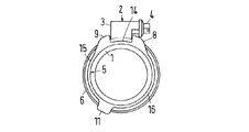
図1から図4で描かれている、ホース1とホースクランプとの接続において、ホース1は、その短い端部分のみが描かれ、ホースクランプは、ウォーム駆動クランプの形で描かれ、ハウジング3及びクランプねじ4からなるホースクランプの閉止2は、概略的に描かれるのみである。この接続は、弾性ゴムリング5を備える。リング5は、図5から図8に詳細に描かれており、取り外し可能な形で、ホース1を弾性プリテンションで囲んでいる。
In the connection between the
ホース1はゴムからなり、オプションとして更に、織布層を有する。しかし、可撓性及び弾性の熱可塑性材料で構成されてもよい。リング5もまた、ゴム又はプラスチックの材料で構成されてもよい。
The
ホースクランプのクランプストラップ6は、クランプねじ4のねじ山とかみ合うように、外側に、リブ形のねじ山部分(図示なし)を備え、クランプねじ4の端は、閉止2内で重なり合う。クランプストラップ6は、半径方向のほぼフック形の突起7−12の間に固定される。突起7−12はリング5のエッジ上に形成される。リング5は、クランプストラップ6の下に、取り外し可能な形で弾性プリテンションでホース1に締め付けられる。リング5の一方の側の突起7、10、12と、他方の側の突起8、9、11との間に位置する軸領域13(図5から図8)におけるリング5の厚さDは、(装填されていない状態の)ホース1の壁の厚さの約5%から9%である。図の実施例では、厚さは約6%から8%で、つまり、厚さDは約0.3mmから0.4mmで、ホース1の壁の厚さは約5mmである。
The
ホースクランプの閉止2の前及び後ろに、2つのフック形の突起7、8及び9、10の2対がリング5上に形成され、それぞれリング5のエッジ上に互いに向かい合うように位置する。これらフック形の突起7−10は、クランプストラップ6のエッジとかみ合う。さらに、3対目の2つのさらなるフック形の突起11及び12が、それぞれリング5のエッジ上に互いに向かい合うように形成される。この突起11、12もまた、それぞれクランプストラップ6のエッジの1つとかみ合う。突起11、12の中心は、閉止2の前及び後ろに配置された突起の組7、8と9、10との間の中心に対し、ホースクランプの両方の円周方向に90°以上の角度スペースβを有する(図5)。ホースクランプの1つの円周方向において、第3の突起対11、12の中心への角度スペースは、140°から170°の間であり、図の実施例では、約155°である(図5)。
Before and after the
弾性ゴムリング5は、突起10−12の間の円周方向のエッジに円周ビーズ14−19を備え、該ビーズの半径方向外側の断面は、反対の軸方向の外側にかつ半径方向外側に増加する。さらに、ビーズ14−19の半径方向内側の断面は、リング5の反対の軸方向の外側に半径方向内側に増加する。
The
さらに、突起7−12は、クランプストラップのエッジとかみ合う突出部20を有し、該突出部20は向かい合う突起7−12に対する方向に、半径方向外側から内側に向かって増加する断面を有する。
Further, the protrusion 7-12 has a
ホース1とリング5の、取り外し可能な構成によって、ホースとリングが別々に製造できるという利点を有する。長さは異なるが、直径と壁の厚さが同じであるホースには、1つの溶接ツールのみが必要なだけである。始めに、相対的に長いホース1が作られ、異なる長さのホース部分がそこからカットされる。すべてのホースに対して、同じ弾性ゴムリング5が使用できる。従って、リングに対して1つの溶接ツールのみが必要なだけである。リング5は、ホースの壁の厚さと比べて相対的に薄いので、ホース1及びリング5の全体のふるまいにはごくわずかに影響を与えるのみであるだけでなく、ホース上に容易に配置することもでき、ホース及び予め組み立てられた締め付けていないホースクランプと共に、パイプソケットの上にソケットの固定リブで押し出すこともできる。
The removable configuration of the
2つの突起対7、8及び9、10は、ホースクランプの締め付けの前及び間の、閉止2の変位を防ぐ。
The two
さらなる突起対11、12は、締め付けのための閉止が、軸方向に手で保持されていて、且つ、そうすることによって又はねじまわしによってホースクランプの軸方向に装填されるとき、その締め付けの間にクランプストラップ6の位置が傾斜してしまうのを防ぐ。傾斜は、例えばクランプねじがねじまわしによって偶然傾斜してかみ合い、そのねじまわしによってクランプねじ4を締め付けるときの、閉止のクランプねじ4に作用する圧力の軸方向の成分によってである。
The further pair of
一方の、最初の2つの突起対7、8及び9、10の中心と、他方の第3の突起対11、12との間の角度スペースβは、第3の突起対11、12が最初の2つの突起対に完全に正反対には配列されないように選択され、突起対7、8と突起対11、12との間の時計回りの方向に配列された、リング5の円周領域のホースクランプとリング5との間のばねの配列のための十分なスペースを提供し、熱や圧力によって生じるホース1の壁の厚さの変化を補償する。そのようなばねは、例えば、独国特許4 127 017 C1で開示されている。突起7−12の間の、リング5の外側及び内側のエッジ上のほぼ三角形の断面の形のビーズ14−19は、少ない材料しか必要としない。これらは直接ホースクランプによって加圧されず、従ってホースクランプの締め付け圧力とは関係なく形を維持する。同時に、これらビーズは、フック形の突起7−12に加え、リング5上のホースクランプの軸方向の変位を防ぐ。
On the other hand, the angular space β between the center of the first two
リング5に対して内側に突出しているビーズ14−19の部分は、ホースクランプの締め付けに影響を及ぼし、それは、図3及び図4で示されているように、各突起対の2つのフック形の突起が互いに対して傾斜しているからであり、よってクランプストラップ6にますます堅くかみ合うことができる。
The portion of the beads 14-19 projecting inwardly with respect to the
突起7−12の突出部20は、リングの円周に向かって内側に傾斜した突出リッジを有し、この傾斜した配置によって突起7−12の間のクランプストラップ6の挿入が容易になる。
The
リング5は、原則として、他のホースクランプ、例えばばねバンドクランプや、クランプあご及びクランプねじを備えたホースクランプを予め組み立てておくことにも適している。
The
本発明の原理を図解するために、本発明の特定の実施例が示され、詳細に記述されているが、本発明はそのような原理から逸脱することなく、他の方法でも実施され得ることが理解されるであろう。 While specific embodiments of the invention have been shown and described in detail to illustrate the principles of the invention, the invention may be practiced in other ways without departing from such principles. Will be understood.
1 ホース
2 閉止
3 ハウジング
4 クランプねじ
5 弾性ゴムリング
6 クランプストラップ
7、8、9、10、11、12 突起
13 軸領域
14、15、16、17、18、19 円周ビーズ
20 突出部
D 厚さ
DESCRIPTION OF
Claims (7)
取り外し可能な形で、弾性プリテンションで前記ホース(1)を囲むように構成された弾性ゴムリング(5)を備え、
前記リング(5)は、前記ホースクランプのクランプストラップ(6)の下に位置し、
前記リング(5)は、半径方向フック形の第1の突起(7−10)を備え、該第1の突起(7−10)は、前記クランプストラップ(6)のエッジとかみ合うことによって、前記第1の突起(7−10)の間の前記ホースクランプの前記クランプストラップ(6)を固着するように構成され、
前記第1の突起(7−10)は、前記リング(5)のエッジ上に形成され、
前記第1の突起(7−10)の間の軸方向に位置する領域の前記リング(5)の厚さ(D)は、前記ホース(1)の壁の厚さの5%から9%であることを特徴とする接続。 A connection between the hose clamp and the hose (1),
An elastic rubber ring (5) configured to surround the hose (1) with elastic pretension in a removable form;
The ring (5) is located under the clamp strap (6) of the hose clamp;
Said ring (5) comprises a radial hook-shaped first protrusion (7-10), said first protrusion (7-10) engaging said edge of said clamp strap (6), said Configured to secure the clamp strap (6) of the hose clamp between first protrusions (7-10);
The first protrusion (7-10) is formed on an edge of the ring (5);
The thickness (D) of the ring (5) in the axially located region between the first protrusions (7-10) is between 5% and 9% of the wall thickness of the hose (1). A connection characterized by being.
前記リング(5)の円周方向から見ると、前記第1の突起(7−10)のうちの2つは、第1の突起対(7、8)として前記閉止(2)の前に互いに向かい合って位置し、且つ、前記第1の突起(7−10)のうちの2つは、第2の突起対(9、10)として前記閉止(2)の後ろに互いに向かい合って位置することを特徴とする請求項1に記載の接続。 The hose clamp has a closure (2) for tightening the clamp strap (6);
When viewed from the circumferential direction of the ring (5), two of the first protrusions (7-10) are mutually connected as a first protrusion pair (7, 8) before the closing (2). And two of the first protrusions (7-10) are located opposite each other behind the closure (2) as a second protrusion pair (9, 10). The connection according to claim 1, characterized in that:
前記第2の突起(11、12)の中心は、前記第1突起対と第2突起対(7、8;9、10)との間の中心から、前記ホースクランプの第1及び第2の円周方向へ90°以上の角度スペースで間隔が開いていることを特徴とする請求項2に記載の接続。 The ring (5) has a second two hook-shaped protrusions (11, 12) located on the edges of the ring (5), facing each other, and the second protrusion (11, 12). Meshes with the edge of the clamp strap (6),
The center of the second protrusion (11, 12) is from the center between the first protrusion pair and the second protrusion pair (7, 8; 9, 10), and the first and second of the hose clamp. 3. Connection according to claim 2, characterized in that the gap is open at an angular space of 90 [deg.] Or more in the circumferential direction.
The first and second protrusions (7-12) have a protrusion (20) that engages with an edge of the clamp strap (6), and the protrusion (20) is the first and second protrusions. 7. The method according to claim 1, further comprising: a cross section that increases in a direction from a radially outer position to a radially inner position in a direction relative to one of (7-12). Connection.
Applications Claiming Priority (1)
| Application Number | Priority Date | Filing Date | Title |
|---|---|---|---|
| DE102004006658A DE102004006658B3 (en) | 2004-02-11 | 2004-02-11 | Connecting clip for hose has projections on edges of rubber-elastic ring below clip band, releasable under elastic pre-stressing |
Publications (2)
| Publication Number | Publication Date |
|---|---|
| JP2005226835A JP2005226835A (en) | 2005-08-25 |
| JP3998020B2 true JP3998020B2 (en) | 2007-10-24 |
Family
ID=33560437
Family Applications (1)
| Application Number | Title | Priority Date | Filing Date |
|---|---|---|---|
| JP2005034282A Expired - Fee Related JP3998020B2 (en) | 2004-02-11 | 2005-02-10 | Hose clamp and hose connection |
Country Status (6)
| Country | Link |
|---|---|
| US (1) | US7093328B2 (en) |
| EP (1) | EP1564471B1 (en) |
| JP (1) | JP3998020B2 (en) |
| CA (1) | CA2496397C (en) |
| DE (2) | DE102004006658B3 (en) |
| ES (1) | ES2275243T3 (en) |
Families Citing this family (9)
| Publication number | Priority date | Publication date | Assignee | Title |
|---|---|---|---|---|
| US7895565B1 (en) | 2006-03-15 | 2011-02-22 | Jp Morgan Chase Bank, N.A. | Integrated system and method for validating the functionality and performance of software applications |
| DE102006048336B4 (en) | 2006-10-12 | 2013-07-04 | Norma Germany Gmbh | hose clamp |
| DE102006048344B4 (en) | 2006-10-12 | 2009-10-08 | Norma Germany Gmbh | hose clamp |
| JP4851959B2 (en) * | 2007-02-20 | 2012-01-11 | 東海ゴム工業株式会社 | Hose clamp holding structure |
| JP5348641B1 (en) * | 2012-07-25 | 2013-11-20 | 株式会社トヨックス | Band set for pipe connection and attachment for tightening band |
| US8757133B2 (en) * | 2012-08-27 | 2014-06-24 | Cummins Intellectual Property, Inc. | Gaseous fuel and intake air mixer for internal combustion engine |
| DE102012020224A1 (en) * | 2012-10-16 | 2014-04-17 | Mann + Hummel Gmbh | Hose-side link assembly of tube connector of hose for supplying fluid e.g. fuel to internal combustion engine of motor car, engages lateral protruding portion of lock of hose clamp with gap based on longitudinal axis of hose end |
| US9944415B2 (en) * | 2016-02-20 | 2018-04-17 | Hui Lin | Filling container |
| CN112431978A (en) * | 2020-12-16 | 2021-03-02 | 李佳佳 | Hose connecting device for air feeder and using method thereof |
Family Cites Families (9)
| Publication number | Priority date | Publication date | Assignee | Title |
|---|---|---|---|---|
| US1694664A (en) * | 1927-09-02 | 1928-12-11 | William H Logan | Hose clamp |
| US2283179A (en) * | 1940-08-14 | 1942-05-19 | Adelbert P Buckingham | Soil pipe hub clamp |
| US2433602A (en) * | 1947-03-26 | 1947-12-30 | Flex O Tube Company | Reusable type hose coupling |
| US3694869A (en) * | 1970-05-22 | 1972-10-03 | Norio Matsura | Tube fastener |
| DE4127017C1 (en) * | 1990-02-22 | 1992-04-23 | Rasmussen Gmbh, 6457 Maintal, De | Hose clip with clamping strip and radial spring - which is integrally formed with clamping strip lug |
| DE19501615A1 (en) * | 1995-01-20 | 1996-08-08 | Porsche Ag | Elastic tube element with end side retainer for clamping band |
| DE19533553C2 (en) | 1995-09-11 | 1998-01-29 | Rasmussen Gmbh | Device for clamping a hose end section pushed onto a pipe end section |
| GB2326920A (en) * | 1997-07-01 | 1999-01-06 | Rasmussen Gmbh | Clamp for clamping a hose on a pipe portion |
| EP1208322B1 (en) * | 2000-06-27 | 2004-07-21 | Phoenix AG | Tube arrangement |
-
2004
- 2004-02-11 DE DE102004006658A patent/DE102004006658B3/en not_active Expired - Fee Related
-
2005
- 2005-01-26 US US11/043,383 patent/US7093328B2/en not_active Expired - Fee Related
- 2005-01-26 ES ES05001577T patent/ES2275243T3/en active Active
- 2005-01-26 EP EP05001577A patent/EP1564471B1/en not_active Expired - Fee Related
- 2005-01-26 DE DE502005000269T patent/DE502005000269D1/en active Active
- 2005-02-09 CA CA002496397A patent/CA2496397C/en not_active Expired - Fee Related
- 2005-02-10 JP JP2005034282A patent/JP3998020B2/en not_active Expired - Fee Related
Also Published As
| Publication number | Publication date |
|---|---|
| EP1564471A3 (en) | 2006-02-15 |
| CA2496397C (en) | 2008-04-29 |
| EP1564471A2 (en) | 2005-08-17 |
| DE102004006658B3 (en) | 2005-02-03 |
| CA2496397A1 (en) | 2005-08-11 |
| DE502005000269D1 (en) | 2007-02-15 |
| US7093328B2 (en) | 2006-08-22 |
| JP2005226835A (en) | 2005-08-25 |
| EP1564471B1 (en) | 2007-01-03 |
| ES2275243T3 (en) | 2007-06-01 |
| US20050172460A1 (en) | 2005-08-11 |
Similar Documents
| Publication | Publication Date | Title |
|---|---|---|
| JP3998020B2 (en) | Hose clamp and hose connection | |
| US7909369B2 (en) | Coupling for joining two pipes | |
| EP0999397B1 (en) | Tubular element with sealing means and a method for manufacturing the tubular element | |
| JP2008531952A (en) | Pipe clamp assembly with V-ring insert | |
| JP2007182993A (en) | Coupling assembly with pipe sockets of fluid retaining components to be joined | |
| JP2001295974A (en) | Pipe joint | |
| JP2008232435A (en) | Seal for sensor packed small | |
| JP2007024237A (en) | Elastic construction of hose clamp | |
| JP2007032839A (en) | Clump with attachment element | |
| JP5833414B2 (en) | Electrofused joint, joining method using the same, and joint structure between electrofused joint and synthetic resin pipe | |
| JP3945469B2 (en) | Hose clamp and hose connection to pre-position hose clamp | |
| JP2008514873A (en) | Clamp ring for securing the gas generator cartridge | |
| JP2006300286A (en) | Joint structure of pipe end portion | |
| JP4063274B2 (en) | Hose coupling | |
| JP2007247855A (en) | Tube fitting | |
| JP2001177964A (en) | Device for joining buried pipe to connection, and junction structure using this | |
| JP2007107618A (en) | Pipe fitting and its protective cap | |
| JPH0491A (en) | Hose connection structure | |
| JP2001254883A (en) | Joint for corrugate pipe | |
| JP2010106966A (en) | Hose clamp | |
| JP3834756B2 (en) | Pipe fitting | |
| JP5781378B2 (en) | Protective structure of inner core in joint | |
| JP6369118B2 (en) | Branch joint | |
| JP2003003506A (en) | Structure of connection between ribbed pipe and manhole, and diameter-enlarged band | |
| JP2006057798A (en) | Hose fastener |
Legal Events
| Date | Code | Title | Description |
|---|---|---|---|
| TRDD | Decision of grant or rejection written | ||
| A01 | Written decision to grant a patent or to grant a registration (utility model) |
Free format text: JAPANESE INTERMEDIATE CODE: A01 Effective date: 20070717 |
|
| A61 | First payment of annual fees (during grant procedure) |
Free format text: JAPANESE INTERMEDIATE CODE: A61 Effective date: 20070730 |
|
| R150 | Certificate of patent or registration of utility model |
Free format text: JAPANESE INTERMEDIATE CODE: R150 |
|
| FPAY | Renewal fee payment (event date is renewal date of database) |
Free format text: PAYMENT UNTIL: 20100817 Year of fee payment: 3 |
|
| FPAY | Renewal fee payment (event date is renewal date of database) |
Free format text: PAYMENT UNTIL: 20100817 Year of fee payment: 3 |
|
| FPAY | Renewal fee payment (event date is renewal date of database) |
Free format text: PAYMENT UNTIL: 20100817 Year of fee payment: 3 |
|
| R154 | Certificate of patent or utility model (reissue) |
Free format text: JAPANESE INTERMEDIATE CODE: R154 |
|
| LAPS | Cancellation because of no payment of annual fees |