JP3994012B2 - Specimen measuring apparatus and method using network - Google Patents
Specimen measuring apparatus and method using network Download PDFInfo
- Publication number
- JP3994012B2 JP3994012B2 JP2002000745A JP2002000745A JP3994012B2 JP 3994012 B2 JP3994012 B2 JP 3994012B2 JP 2002000745 A JP2002000745 A JP 2002000745A JP 2002000745 A JP2002000745 A JP 2002000745A JP 3994012 B2 JP3994012 B2 JP 3994012B2
- Authority
- JP
- Japan
- Prior art keywords
- measurement
- unit
- input
- data
- output unit
- Prior art date
- Legal status (The legal status is an assumption and is not a legal conclusion. Google has not performed a legal analysis and makes no representation as to the accuracy of the status listed.)
- Expired - Lifetime
Links
Images


Description
【0001】
【発明の属する技術分野】
本発明は、ネットワークによる検体(サンプル)測定装置およびその方法に関し、さらに詳しくは、例えば血液を採取した場所で血液サンプルの測定を行い、その測定データをデータ処理装置に送信して血液の分析を行う血液分析装置のようなネットワークによる検体測定装置およびその方法に関する。
【0002】
【従来の技術】
従来のこの種の血液分析装置の一例を図3に示す。この図において、31は測定装置、32はCRTディスプレイ装置を備えたデータ処理装置、33はページプリンタ、34はカラーグラフィックプリンタ、35は空圧源部、36はサンプラ部、37はデータプリンタである。
【0003】
測定装置31は血液サンプルの測定、制御を行う。すなわち、測定装置31は、入力部、出力部として、パネルキーボードLCD画面31aを備えており、動作命令の入力を受け付け、動作制御内容や測定結果を表示する。データ処理装置32は測定装置31より得られた測定データの処理を行う。ページプリンタ33は測定情報や測定結果のリストを印字する。カラーグラフィックプリンタ34は粒度分布図、スキャッタグラムなどの測定結果や画面のハードコピーを印字する。空圧源部35は測定装置31で使用する陽圧、バキューム圧を供給する。サンプラ部36は血液サンプルを自動的に測定装置31へ供給する。データプリンタ37は測定データを検査伝票形式の用紙に印字する。
【0004】
図4は図3で示した血液分析装置の内部構成を示すブロック図である。
測定装置31は、入力部311、出力部312、動作制御部313、動作機構部314、測定部315、A/D変換部316、測定データ計算部317、測定装置側入出力部318から構成されている。入力部311及び出力部312はパネルキーボードLCD画面31aに対応している。
【0005】
データ処理装置32は、マイクロプロセッサ,ROM,RAM,I/Oポートからなるパーソナルコンピュータを用いて作製され、入力部321、出力部322、処理装置側入出力部323、測定データ処理部324から構成されている。
【0006】
測定装置31とデータ処理装置32は、離れて配置され、測定装置31からデータ処理装置32に測定データを送信することが可能な構成となっている。すなわち、測定装置31側の入出力部318とデータ処理装置32側の入出力部323とは、ともに汎用インターフェイスであるTCP/IP(Transmission control protocol//internet protocol:トランスミッション コントロール プロトコル/インターネット プロトコル)で構成されており、光ケーブルあるいは同軸ケーブルを用いたLAN38で接続されている。
【0007】
測定装置31の各構成要素について説明すれば、入力部311からは、使用者により、検体測定の動作命令が入力され、入力された動作命令は動作制御部313に送られる。出力部312は、動作制御部313で行う動作制御の内容を表示する。
【0008】
動作制御部313は、入力部311から入力された動作命令に従って、動作制御データを生成し、その動作制御データを動作機構部314に送る。
動作機構部314は、動作制御部313から与えられた動作制御データに従って血液の測定動作を行う。
【0009】
測定部315は、この測定動作で血液サンプルの測定を行って、その測定した生のデータをA/D変換部316に送る。
A/D変換部316は、測定部315で得られたアナログデータをデジタルデータに変換し、測定データ計算部317に送る。
【0010】
測定データ計算部317は、A/D変換部316から受けた生データの計算を行い、その計算結果を測定装置側入出力部318に送る。具体的には、例えば、血液サンプルを抵抗式測定原理にて測定して血球数をカウントし、血球数を算出して、その算出結果を測定装置側入出力部318に送る。
測定装置側入出力部318は、測定データ計算部317から受けた測定データの計算結果をデータ処理装置32側に送信する。
【0011】
次に、データ処理装置32の各構成要素について説明すれば、入力部321は、測定データ処理部324における処理の指示入力を行う。
出力部322は、上述のCRTディスプレイ装置、ページプリンタ33、およびカラーグラフィックプリンタ34で構成され、測定データ処理部324で処理された処理結果のデータを出力する。
【0012】
処理装置側入出力部323は、測定装置31の入出力部318から受けた測定データの計算結果を測定データ処理部324に送る。
測定データ処理部324は、測定データ計算部317から送られてきた計算結果を表示用、印字用のデータに処理し、その処理結果を出力部322に送る。また、測定データ処理部324は、測定データ計算部317から送られてきた計算結果をデータ処理装置32のハードディスクに格納する。
【0013】
このように、従来のネットワークによる検体測定装置では、血液を採取した場所で血液サンプルの測定を行い、その測定データを離れた場所にあるデータ処理装置に送信して、血液の分析を行うようにしていた。
【0014】
【発明が解決しようとする課題】
しかしながら、このような従来のネットワークによる検体測定装置では、測定装置31側で検体測定の動作命令を入力するようにしていたので、測定装置31側に操作に習熟した人員を配置する必要があり、この点に関する改良が望まれていた。
【0015】
この発明は、このような事情を考慮してなされたもので、測定装置とデータ処理装置とで構成された検体測定装置において、データ処理装置の側から測定装置に対して、検体測定の動作命令を入力できるようにすることを目的とするものである。
【0016】
【課題を解決するための手段】
本発明は、検体測定の動作命令に従って検体の測定動作を行う動作機構部、動作機構部の動作で検体の測定を行って測定データを得る測定部、および測定部で得られた測定データをネットワークに送信する入出力部からなる測定装置と、測定装置からネットワークを介して測定データを得る入出力部、入出力部から測定データを受け取って測定データの演算を行い、スキャッタグラムまたは粒度分布図を作成する測定データ演算部、および測定データ演算部で得られた演算結果としてスキャッタグラムまたは粒度分布図を出力する出力部からなるデータ処理装置を備え、検体測定の動作命令を入力する入力部が、データ処理装置に設けられ、この入力部で入力された動作命令が、データ処理装置の入出力部と測定装置の入出力部を介して、測定装置の動作機構部に送られることを特徴とするネットワークによる検体測定装置である。
【0017】
本発明によれば、データ処理装置の側から測定装置に対して、検体測定の動作命令を入力することができるので、測定装置側に操作に習熟した人員を配置する必要がなくなり、人員の有効配置を図ることができる。
【0018】
【発明の実施の形態】
本発明において、動作機構部としては、検体測定の動作命令に従って測定動作を行うことができるものであればよく、当該分野で公知の各種の動作機構部を適用することができる。例えば、本発明を血液分析装置に適用した場合であれば、サンプル容器が保持されたサンプルラックをサンプル採取位置まで順次移動させ、サンプル採取位置に到達したサンプルラックからサンプル容器を抜き取り、サンプル容器を撹拌した後、サンプル容器から血液サンプルを採取して、その血液サンプルをノズル内に通過させる等の動作を行うことができるものを適用することができる。
【0019】
この動作機構部は、測定動作が正常に行われているのか否かを検出するセンサを有し、このセンサの検出内容が、測定装置の入出力部とデータ処理装置の入出力部を介して、データ処理装置の出力部から出力されるように構成しておくことが望ましい。このセンサとしては、例えば、サンプルラックが正常に移送されているのか否か、また、サンプル容器の撹拌機構が正常に動作しているのか否か等を検出するセンサが挙げられる。
【0020】
このように構成しておけば、動作機構部の測定動作が正常に行われているのか否かをデータ処理装置側で確認することができるので、測定装置側でトラブルが発生した場合でも、測定装置側のトラブルの内容をデータ処理装置側で判断して、その対応をデータ処理装置側から測定装置側へ指示することができる。
【0021】
測定部としては、動作機構部の動作で検体の測定を行って測定データを得ることができるものであればよく、当該分野で公知の各種の測定部を適用することができる。例えば、上記と同様に本発明を血液分析装置に適用した場合であれば、ノズル内を通過する血液サンプルを抵抗式測定原理で測定する、あるいはフローセルを通過する血液サンプルの光学特性を測定する等の測定を行うことができるものを適用することができる。
【0022】
測定装置側の入出力部およびデータ処理装置側の入出力部としては、ともに、例えば専用回線や構内LAN、あるいはインターネットのようなネットワークを介してデータの送受信ができるものであればよく、例えば、汎用インターフェイスであるTCP/IPなどを適用することができる。
【0023】
測定データ演算部としては、入出力部から測定データを受け取って測定データの演算を行うことができるものであればよく、当該分野で公知の各種の測定データ演算部を適用することができる。この測定データ演算部は、測定データ計算部と測定データ処理部から構成されていることが望ましい。測定データ計算部としては、例えば、上記と同様に本発明を血液分析装置に適用した場合であれば、血液サンプルを抵抗式測定原理にて測定して血球数をカウントし、粒度分布図を作成したり、血液サンプルの光学特性からスキャッタグラムなどを作成して血球情報を算出する等の測定データの計算を行うことができるものを適用することができる。また、測定データ処理部としては、血球数のデータや粒度分布やスキャッタグラムなどを表示用、印字用のデータに処理し、その処理結果を出力部に送ったり、その処理結果をデータ処理装置のハードディスクに格納したりする等の測定データの処理を行うことができるものを適用することができる。
【0024】
出力部としては、測定データ演算部で得られた演算結果を出力することができるものであればよく、各種の表示装置や、測定情報や測定結果のリスト、粒度分布図、スキャッタグラムなどの測定結果や、画面のハードコピー等の印刷が可能な各種のプリンタを適用することができる。
【0025】
本発明においては、検体測定の動作命令を入力する入力部が、データ処理部側に設けられ、この入力部で入力された動作命令が、データ処理装置の入出力部と測定装置の入出力部を介して、測定装置の動作機構部に送られる構成である。
【0026】
この入力部は、検体測定の動作命令を入力することができるものであればよく、キーボード、あるいはマウスやタッチペンのような各種のポインティングデバイスを適用することができる。
【0027】
本発明においては、一台のデータ処理装置に複数台の測定装置を接続するようにしてもよい。この場合、入力部から入力する動作命令がどの測定装置に対するものなのか、また測定装置から送出される測定データがどの測定装置からのものなのかが分かるように、測定装置とデータ処理装置を構成しておく。例えば、各測定装置にアドレスを付与しておき、そのアドレスとともにデータの送受信を行うようにする。
【0028】
測定装置は、例えば、病院、臨床検査場、保険所などの血液サンプルを直接入手することが可能な現場に配置することができる。一方、データ処理装置は、公共または民間のデータ処理センター、病院のコンピュータ室などの事務処理センターに配置することができる。ただし、配置場所はこれらに限定されるものではなく、両装置を同じ部屋に配置してもよい。
【0029】
以下、図面に示す実施の形態に基づいて本発明を詳述する。なお、本発明はこれによって限定されるものではなく、各種の変形が可能である。
【0030】
図1は本発明の検体測定装置の一実施形態の全体を示す説明図である。本実施形態では、本発明を血液分析装置に適用した例を示している。
この血液分析装置は、測定装置1、CRTディスプレイ装置を備えたデータ処理装置2、ページプリンタ3、カラーグラフィックプリンタ4、空圧源部5、サンプラ部6、データプリンタ7で構成されている。
【0031】
測定装置1は血液サンプルの測定を行う。データ処理装置2は測定装置1より得られた測定データの処理を行う。ページプリンタ3は測定情報や測定結果のリストを印字する。カラーグラフィックプリンタ4は粒度分布図、スキャッタグラムなどの測定結果や画面のハードコピーを印字する。空圧源部5は測定装置1で使用する陽圧、バキューム圧を供給する。サンプラ部6は血液サンプルを自動的に測定装置1へ供給する。データプリンタ7は測定データを検査伝票形式の用紙に印字する。
【0032】
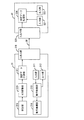
図2は図1で示した血液分析装置の内部構成を示すブロック図である。
測定装置1は、動作機構部11、測定部12、A/D変換部13、測定装置側入出力部14から構成されている。
【0033】
データ処理装置2は、マイクロプロセッサ,ROM,RAM,I/Oポートからなるパーソナルコンピュータを用いて作製され、入力部21、出力部22、動作制御部23、処理装置側入出力部24、測定データ計算部25、測定データ処理部26から構成されている。
【0034】
測定装置1とデータ処理装置2は、離して配置することができ、双方でデータのやり取りが可能な構成となっている。すなわち、測定装置1側の入出力部14とデータ処理装置2側の入出力部24とは、ともに汎用インターフェイスであるTCP/IPで構成されており、光ケーブルあるいは同軸ケーブルを用いたLAN8で接続され、相互にデータの送受信が可能となっている。
【0035】
測定装置1は、病院の検査室に配置され、データ処理装置2は、病院のコンピュータ室に配置される。
【0036】
まず、測定装置1の各構成要素について説明する。
動作機構部11は、測定装置側入出力部14を介して与えられた動作制御データに従って血液の測定動作を行う。具体的には、例えば、サンプル容器が保持されたサンプルラックをサンプル採取位置まで順次移動させ、サンプル採取位置に到達したサンプルラックからサンプル容器を抜き取り、サンプル容器を撹拌した後、サンプル容器から血液サンプルを採取して、その血液サンプルをノズル内に通過させる等の動作を行う。
【0037】
この動作機構部11は、測定動作が正常に行われているのか否かを検出するセンサを有している。このセンサは、具体的には、例えば、サンプルラックが正常に移送されているのか否か、また、サンプル容器の撹拌機構が正常に動作しているのか否か等を検出するセンサである。そして、このセンサの検出内容は、測定装置側入出力部14と処理装置側入出力部24を介して、データ処理装置2の動作制御部23に送られる。
【0038】
測定部12は、血液サンプルの測定を行って、その測定した生のデータをA/D変換部13に送る。この測定した生のデータはアナログデータである。具体的には、例えば、ノズル内を通過する血液サンプルを抵抗式測定原理にて測定し、その測定データをA/D変換部13に送る。
A/D変換部13は、測定部12で得られたアナログデータをデジタルデータに変換し、測定装置側入出力部14に送る。
【0039】
測定装置側入出力部14は、A/D変換部13から受けたデジタルデータを処理装置2側に送信する。また、データ処理装置2から受信した動作制御データを動作機構部11に送る。この動作制御データはデジタルデータである。さらに、測定装置側入出力部14は、動作機構部11に設けられたセンサの検出内容を処理装置2側に送信する。
【0040】
次に、データ処理装置2の各構成要素について説明する。入力部21からは、使用者により、検体測定の動作命令が入力され、入力された動作命令は動作制御部23に送られる。入力部21からの動作命令の入力は、CRTディスプレイ装置のアイコンを指示することで行う。
【0041】
出力部22は、上述のCRTディスプレイ装置、ページプリンタ3、カラーグラフィックプリンタ4、およびデータプリンタ7で構成され、動作制御部23で行う動作制御の内容や、測定データ処理部26で処理された処理結果のデータを出力する。また、動作制御部23から送られてきた、測定装置1の動作機構部11に設けられたセンサの検出内容を出力する。
【0042】
具体的には、上述したように、ページプリンタ3で測定情報や測定結果のリストを印字し、カラーグラフィックプリンタ4で粒度分布図、スキャッタグラムなどの測定結果や画面のハードコピーを印字し、データプリンタ7で測定データを検査伝票形式の用紙に印字する。また、測定装置1の動作機構部11に設けられたセンサの検出内容をCRTディスプレイ装置に表示する。
【0043】
動作制御部23は、入力部21から入力された動作命令に従って、動作制御データを生成し、その動作制御データを処理装置側入出力部24に送る。また、動作制御部23は、測定装置1の動作機構部11に設けられたセンサの検出内容を受信し、この検出内容を出力部22に送る。
【0044】
処理装置側入出力部24は、動作制御部23から受けた動作制御データを、測定装置1の測定装置側入出力部14に送信する。また、測定装置側入出力部14を介して送信された測定データを測定データ計算部25に送り、さらに、測定装置1の動作機構部11に設けられたセンサの検出内容を動作制御部23に送る。
【0045】
測定データ計算部25は、測定装置1側の入出力部14から受けた生データの計算を行い、その計算結果を測定データ処理部26に送る。具体的には、例えば、血液サンプルの抵抗式測定値から血球数をカウントし、血球数を算出して、粒度分布やスキャッタグラムなどを作成し、測定データ処理部26に送る。この測定データ計算部25は、データ処理装置2の外部に設けたものであってもよい。例えば、サーバ等の別のパーソナルコンピュータ上に設けられた測定データ計算部25aであってもよい。
【0046】
測定データ処理部26は、測定データ計算部25から送られた計算結果を表示用、印字用のデータに処理し、その処理結果を出力部22に送る。具体的には、例えば、測定データ計算部25で作成した粒度分布やスキャッタグラムなどを表示用、印字用データに処理して、CRTディスプレイ装置、ページプリンタ3、カラーグラフィックプリンタ4、およびデータプリンタ7などの出力部22に送る。また、測定データ処理部26は、測定データ計算部25から送られてきた計算結果をデータ処理装置2のハードディスクに格納する。
【0047】
全体の動作は以下のようになっている。
まず、データ処理装置2側の入力部21から動作命令が入力されると、その動作命令は、動作制御部23に送られて動作制御データが生成され、その動作制御データは、処理装置側入出力部24と測定装置側入出力部14を介して、動作機構部11に送られ、適切な測定動作が行われる。また、動作機構部11に設けられたセンサの検出結果が出力部22に出力されて、測定動作が正常に行われているのか否かがモニタされる。
【0048】
そして、測定動作に応じて、測定部12によって測定データが得られ、得られた測定データは、A/D変換部13によってデジタルデータ変換され、その測定データは、測定装置側入出力部14と処理装置側入出力部24を介して、測定データ計算部25に送られる。測定データ計算部25では、測定データの計算を行って、そのデータを測定データ処理部26に送る。測定データ処理部26は、測定データの処理を行い、その処理結果を出力部22に送り、出力部22はその処理結果を出力する。また、測定データ処理部26は、測定データ計算部25から送られてきた計算結果をデータ処理装置2のハードディスクに格納する。
【0049】
このような構成であれば、例えば、測定装置1を病院、臨床検査場、保険所などの血液サンプルを直接入手することが可能な現場に配置し、データ処理装置2を公共または民間のデータ処理センター、病院のコンピュータ室などの事務処理センターに配置しておき、病院、臨床検査場、保険所などの現場で血液サンプルを測定装置にセットすれば、データ処理装置2側で動作命令を入力して、測定装置の測定動作を行わせることができるので、現場で動作命令の入力操作を行うことなく、血液サンプルを測定することができる。また、測定装置1の動作機構部11のセンサによって、動作機構部11の測定動作が正常に行われているのか否かをデータ処理装置2側で確認することができるので、測定装置1側でトラブルが発生した場合でも、測定装置側1のトラブルの内容をデータ処理装置2側で判断して、その対応をデータ処理装置2側から測定装置1側へ指示することができる。これにより、測定装置を操作するための人員の有効利用や、測定装置の操作や保守作業に習熟するための時間および労力の削減を図ることができる。
【0050】
【発明の効果】
本発明によれば、測定装置とデータ処理装置とで構成された検体測定装置において、データ処理装置の側から測定装置に対して、検体測定の動作命令を入力することができるので、測定装置とデータ処理装置とが離れて配置されていても、測定装置側で動作命令の入力操作を行うことなく、例えば血液サンプルのような検体を測定することができる。これにより、測定装置を操作するための人員の有効利用や、測定装置の操作に習熟するための時間および労力の削減を図ることができる。
【図面の簡単な説明】
【図1】本発明の検体測定装置の一実施形態の全体を示す説明図である。
【図2】図1で示した血液分析装置の内部構成を示すブロック図である。
【図3】従来の血液分析装置の構成を示す説明図である。
【図4】従来の血液分析装置の内部構成を示すブロック図である。
【符号の説明】
1 測定装置
2 データ処理装置
3 ページプリンタ
4 カラーグラフィックプリンタ
5 空圧源部
6 サンプラ部
7 データプリンタ
8 LAN
11 動作機構部
12 測定部
13 A/D変換部
14 測定装置側入出力部
21 入力部
22 出力部
23 動作制御部
24 処理装置側入出力部
25 測定データ計算部
25a 外部に設けた測定データ計算部
26 測定データ処理部[0001]
BACKGROUND OF THE INVENTION
The present invention relates to a specimen (sample) measuring apparatus and method using a network. More specifically, for example, a blood sample is measured at a place where blood is collected, and the measurement data is transmitted to a data processing apparatus to analyze the blood. BACKGROUND OF THE
[0002]
[Prior art]
An example of a conventional blood analyzer of this type is shown in FIG. In this figure, 31 is a measuring device, 32 is a data processing device provided with a CRT display device, 33 is a page printer, 34 is a color graphic printer, 35 is a pneumatic source unit, 36 is a sampler unit, and 37 is a data printer. .
[0003]
The
[0004]
4 is a block diagram showing the internal configuration of the blood analyzer shown in FIG.
The
[0005]
The
[0006]
The
[0007]
Explaining each component of the
[0008]
The
The
[0009]
The
The A /
[0010]
The measurement
The measurement device side input /
[0011]
Next, the components of the
The
[0012]
The processing device side input /
The measurement
[0013]
As described above, in a conventional sample measuring apparatus using a network, a blood sample is measured at a place where blood is collected, and the measurement data is transmitted to a data processing apparatus at a remote place to analyze the blood. It was.
[0014]
[Problems to be solved by the invention]
However, in such a conventional sample measurement device using a network, since the measurement command is input on the
[0015]
The present invention has been made in consideration of such circumstances, and in a sample measuring device constituted by a measuring device and a data processing device, an operation command for sample measurement from the data processing device side to the measuring device. Is intended to be able to input.
[0016]
[Means for Solving the Problems]
The present invention relates to an operation mechanism unit that performs a sample measurement operation in accordance with an operation command for sample measurement, a measurement unit that performs measurement of the sample by the operation of the operation mechanism unit, and obtains measurement data, and the measurement data obtained by the measurement unit to the network a measuring device comprising a output unit for transmitting the input and output portion for obtaining measurement data from the measuring device via a network, you have row calculation of measurement data receiving measurement data from the input-output unit, scattergram or a particle size distribution diagram A data processing device comprising a measurement data calculation unit for generating a scattergram and an output unit for outputting a scattergram or a particle size distribution diagram as a calculation result obtained by the measurement data calculation unit, and an input unit for inputting an operation command for sample measurement Provided in the data processing device, and an operation command input at the input unit is measured via the input / output unit of the data processing device and the input / output unit of the measurement device. An analyte measuring device according to the network, characterized in that it is sent to the operating mechanism of the device.
[0017]
According to the present invention, since an operation command for sample measurement can be input from the data processing device side to the measurement device, it is not necessary to arrange personnel who are familiar with the operation on the measurement device side. Arrangement can be achieved.
[0018]
DETAILED DESCRIPTION OF THE INVENTION
In the present invention, any operation mechanism unit may be used as long as it can perform a measurement operation in accordance with a sample measurement operation command, and various operation mechanism units known in the art can be applied. For example, if the present invention is applied to a blood analyzer, the sample rack holding the sample container is sequentially moved to the sample collection position, the sample container is extracted from the sample rack that has reached the sample collection position, and the sample container is removed. After stirring, a blood sample can be collected from a sample container, and a device that can perform an operation such as passing the blood sample through a nozzle can be applied.
[0019]
This operation mechanism unit has a sensor for detecting whether or not the measurement operation is normally performed, and the detection content of this sensor is transmitted via the input / output unit of the measurement device and the input / output unit of the data processing device. It is desirable to configure so that the data is output from the output unit of the data processing apparatus. Examples of the sensor include a sensor that detects whether or not the sample rack is normally transferred, whether or not the stirring mechanism of the sample container is operating normally, and the like.
[0020]
If configured in this way, it is possible to check on the data processing device side whether or not the measurement operation of the operation mechanism section is normally performed, so even if a trouble occurs on the measurement device side, measurement can be performed. The content of the trouble on the apparatus side can be judged on the data processing apparatus side, and the response can be instructed from the data processing apparatus side to the measuring apparatus side.
[0021]
Any measuring unit may be used as long as the measurement data can be obtained by measuring the sample by the operation of the operation mechanism unit, and various measuring units known in the art can be applied. For example, if the present invention is applied to a blood analyzer as described above, the blood sample passing through the nozzle is measured by the resistance measurement principle, or the optical characteristics of the blood sample passing through the flow cell are measured. It is possible to apply one that can measure the above.
[0022]
As the input / output unit on the measuring device side and the input / output unit on the data processing device side, both can be used as long as they can transmit and receive data via a network such as a dedicated line, a local LAN, or the Internet, for example, A general-purpose interface such as TCP / IP can be applied.
[0023]
Any measurement data calculation unit may be used as long as it can receive measurement data from the input / output unit and calculate measurement data, and various measurement data calculation units known in the art can be applied. The measurement data calculation unit is preferably composed of a measurement data calculation unit and a measurement data processing unit. As the measurement data calculator, for example, if the present invention is applied to a blood analyzer as described above, a blood sample is measured by the resistance measurement principle, the number of blood cells is counted, and a particle size distribution diagram is created. In addition, it is possible to apply one capable of calculating measurement data such as creating a scattergram from the optical characteristics of a blood sample and calculating blood cell information. The measurement data processing unit processes blood cell count data, particle size distribution, scattergram, etc. into display and print data, and sends the processing results to the output unit. A device capable of processing measurement data such as being stored in a hard disk can be applied.
[0024]
The output unit only needs to be able to output the calculation results obtained by the measurement data calculation unit. Various display devices, measurement information and measurement result lists, particle size distribution diagrams, scattergrams, and other measurements are available. Various printers capable of printing the results and hard copy of the screen can be applied.
[0025]
In the present invention, an input unit for inputting a sample measurement operation command is provided on the data processing unit side, and the operation command input by the input unit is input to the input / output unit of the data processing device and the input / output unit of the measurement device. Is sent to the operation mechanism of the measuring device.
[0026]
The input unit may be any unit that can input an operation command for sample measurement, and various pointing devices such as a keyboard or a mouse or a touch pen can be applied.
[0027]
In the present invention, a plurality of measuring devices may be connected to one data processing device. In this case, the measurement device and the data processing device are configured so that it is possible to know which measurement device the operation command input from the input unit is for, and from which measurement device the measurement data sent from the measurement device is. Keep it. For example, an address is assigned to each measuring apparatus, and data is transmitted / received together with the address.
[0028]
The measuring device can be placed at a site where a blood sample can be obtained directly, such as a hospital, clinical laboratory, or insurance. On the other hand, the data processing apparatus can be arranged in a business processing center such as a public or private data processing center or a computer room of a hospital. However, the arrangement location is not limited to these, and both apparatuses may be arranged in the same room.
[0029]
Hereinafter, the present invention will be described in detail based on embodiments shown in the drawings. In addition, this invention is not limited by this, A various deformation | transformation is possible.
[0030]
FIG. 1 is an explanatory diagram showing the entirety of an embodiment of a sample measuring apparatus of the present invention. In this embodiment, an example in which the present invention is applied to a blood analyzer is shown.
This blood analyzer comprises a
[0031]
The measuring
[0032]
FIG. 2 is a block diagram showing an internal configuration of the blood analyzer shown in FIG.
The measuring
[0033]
The
[0034]
The measuring
[0035]
The measuring
[0036]
First, each component of the measuring
The
[0037]
The
[0038]
The
The A /
[0039]
The measurement device side input /
[0040]
Next, each component of the
[0041]
The
[0042]
Specifically, as described above, the page printer 3 prints a list of measurement information and measurement results, and the color
[0043]
The
[0044]
The processing device side input /
[0045]
The measurement
[0046]
The measurement
[0047]
The overall operation is as follows.
First, when an operation command is input from the
[0048]
Then, according to the measurement operation, measurement data is obtained by the
[0049]
With such a configuration, for example, the measuring
[0050]
【The invention's effect】
According to the present invention, in the sample measuring device constituted by the measuring device and the data processing device, an operation command for sample measurement can be input to the measuring device from the data processing device side. Even if the data processing apparatus is arranged apart from the data processing apparatus, it is possible to measure a specimen such as a blood sample without performing an operation command input operation on the measurement apparatus side. Thereby, it is possible to effectively use personnel for operating the measuring apparatus and reduce time and labor for becoming familiar with the operation of the measuring apparatus.
[Brief description of the drawings]
FIG. 1 is an explanatory diagram showing the entirety of an embodiment of a sample measuring apparatus of the present invention.
2 is a block diagram showing an internal configuration of the blood analyzer shown in FIG. 1. FIG.
FIG. 3 is an explanatory view showing a configuration of a conventional blood analyzer.
FIG. 4 is a block diagram showing an internal configuration of a conventional blood analyzer.
[Explanation of symbols]
1
DESCRIPTION OF
Claims (9)
測定装置からネットワークを介して測定データを得る入出力部、入出力部から測定データを受け取って測定データの演算を行い、スキャッタグラムまたは粒度分布図を作成する測定データ演算部、および測定データ演算部で得られた演算結果としてスキャッタグラムまたは粒度分布図を出力する出力部からなるデータ処理装置を備え、
検体測定の動作命令を入力する入力部が、データ処理装置に設けられ、この入力部で入力された動作命令が、データ処理装置の入出力部と測定装置の入出力部を介して、測定装置の動作機構部に送られることを特徴とするネットワークによる検体測定装置。An operation mechanism unit that performs a sample measurement operation according to a sample measurement operation command, a measurement unit that performs measurement of the sample by the operation of the operation mechanism unit, and obtains measurement data, and an input that transmits the measurement data obtained by the measurement unit to the network A measuring device comprising an output unit;
Output unit for obtaining measurement data from the measuring device via a network, have row calculation of measurement data receiving measurement data from the input-output unit, measuring data calculating unit that creates a scattergram or a particle size distribution diagram, and the measurement data operation A data processing device comprising an output unit that outputs a scattergram or a particle size distribution diagram as a calculation result obtained in the unit,
An input unit for inputting an operation command for sample measurement is provided in the data processing device, and the operation command input at the input unit is passed through the input / output unit of the data processing device and the input / output unit of the measurement device. A specimen measurement apparatus using a network, wherein the specimen measurement apparatus is sent to an operation mechanism section of the network.
測定装置からネットワークを介して測定データを得る入出力部、入出力部から測定データを受け取って測定データの演算を行い、スキャッタグラムまたは粒度分布図を作成する測定データ演算部、および測定データ演算部で得られた演算結果としてスキャッタグラムまたは粒度分布図を出力する出力部からなるデータ処理装置を備え、
測定装置の動作機構部が、測定動作が正常に行われているのか否かを検出するセンサを有し、このセンサの検出内容が、測定装置の入出力部とデータ処理装置の入出力部を介して、データ処置装置の出力部から出力されることを特徴とするネットワークによる検体測定装置。An operation mechanism unit that performs a sample measurement operation according to a sample measurement operation command, a measurement unit that performs measurement of the sample by the operation of the operation mechanism unit, and obtains measurement data, and an input that transmits the measurement data obtained by the measurement unit to the network A measuring device comprising an output unit;
Output unit for obtaining measurement data from the measuring device via a network, have row calculation of measurement data receiving measurement data from the input-output unit, measuring data calculating unit that creates a scattergram or a particle size distribution diagram, and the measurement data operation A data processing device comprising an output unit that outputs a scattergram or a particle size distribution diagram as a calculation result obtained in the unit,
The operation mechanism part of the measuring device has a sensor that detects whether or not the measuring operation is normally performed. Through the output unit of the data processing device, the sample measuring device using a network.
データ処理装置の入出力部がネットワークを介して、測定装置の入出力部に動作命令を送信するステップ、
測定装置の動作機構部が入出力部を介して受信した動作命令に従って検体の測定動作を行うステップ、
動作機構部の測定動作によって測定装置の測定部が測定データを得るステップ、
測定装置の入出力部が測定データを、ネットワークを介してデータ処理装置の入出力部に送信するステップ、
データ処理装置の測定データ演算部が入出力部を介して受信した測定データの演算を行い、スキャッタグラムまたは粒度分布図を作成するステップ、および
測定データの演算結果としてスキャッタグラムまたは粒度分布図がデータ処理装置の出力部に出力されるステップ、からなるネットワークによる検体測定方法。A step of inputting a sample measurement operation command from an input unit of the data processing device;
A step in which the input / output unit of the data processing device transmits an operation command to the input / output unit of the measurement device via the network;
A step of measuring the sample according to the operation command received by the operation mechanism unit of the measurement apparatus via the input / output unit;
The measurement unit of the measurement device obtains measurement data by the measurement operation of the operation mechanism unit;
A step in which the input / output unit of the measurement device transmits the measurement data to the input / output unit of the data processing device via the network;
Measuring data calculating unit of the data processing device have line calculation of measurement data received via the input-output unit, a step for creating a scattergram or a particle size distribution diagram, and scattergram or a particle size distribution diagram as a calculation result of the measurement data A sample measurement method using a network comprising steps output to an output unit of a data processing device.
Priority Applications (1)
| Application Number | Priority Date | Filing Date | Title |
|---|---|---|---|
| JP2002000745A JP3994012B2 (en) | 2002-01-07 | 2002-01-07 | Specimen measuring apparatus and method using network |
Applications Claiming Priority (1)
| Application Number | Priority Date | Filing Date | Title |
|---|---|---|---|
| JP2002000745A JP3994012B2 (en) | 2002-01-07 | 2002-01-07 | Specimen measuring apparatus and method using network |
Publications (3)
| Publication Number | Publication Date |
|---|---|
| JP2003202346A JP2003202346A (en) | 2003-07-18 |
| JP2003202346A5 JP2003202346A5 (en) | 2005-08-04 |
| JP3994012B2 true JP3994012B2 (en) | 2007-10-17 |
Family
ID=27641043
Family Applications (1)
| Application Number | Title | Priority Date | Filing Date |
|---|---|---|---|
| JP2002000745A Expired - Lifetime JP3994012B2 (en) | 2002-01-07 | 2002-01-07 | Specimen measuring apparatus and method using network |
Country Status (1)
| Country | Link |
|---|---|
| JP (1) | JP3994012B2 (en) |
Families Citing this family (4)
| Publication number | Priority date | Publication date | Assignee | Title |
|---|---|---|---|---|
| JP4659497B2 (en) | 2005-03-29 | 2011-03-30 | シスメックス株式会社 | Setting method for measuring apparatus, analysis system, data processing apparatus, and application program |
| JP4807769B2 (en) | 2005-03-30 | 2011-11-02 | シスメックス株式会社 | Analysis system, data processing apparatus, and application program |
| JP5976589B2 (en) * | 2013-03-29 | 2016-08-23 | シスメックス株式会社 | Sample analysis method and sample analysis system |
| EP3714460A4 (en) * | 2017-11-20 | 2021-01-20 | Siemens Healthcare Diagnostics, Inc. | User interface for managing a multiple diagnostic engine environment |
-
2002
- 2002-01-07 JP JP2002000745A patent/JP3994012B2/en not_active Expired - Lifetime
Also Published As
| Publication number | Publication date |
|---|---|
| JP2003202346A (en) | 2003-07-18 |
Similar Documents
| Publication | Publication Date | Title |
|---|---|---|
| US9063101B2 (en) | Centralized monitoring system, analyzing system and centralized monitoring method | |
| US6689055B1 (en) | Method and apparatus for acquisition and analysis of non-imaging data collected during ultrasound exam | |
| US20090198539A1 (en) | Onscreen takeoff incorporating typical areas system, method and computer product | |
| WO2010022047A2 (en) | Normalized decimal equivalent systems and methods | |
| JP3994012B2 (en) | Specimen measuring apparatus and method using network | |
| CN107610268A (en) | A kind of station inspection management method | |
| JP2019138711A (en) | Inspection order processor, computer program therefor, and inspection system | |
| CN114388127A (en) | Information management system for mobile medical vehicle | |
| EP2764371B1 (en) | Maintenance arrangement for an analysis device | |
| JPH11122276A (en) | Scientific analysis device with electronic mail function | |
| JP2005091327A (en) | Color management system and its color management method | |
| JP2009250656A (en) | Automatic analysis system | |
| JP2002200077A (en) | Method and system for gaining and analyzing data other than imaging collected during ultrasonic inspection | |
| JP2015082179A (en) | Analyzer information system, analyzer, and user terminal | |
| JP2005267373A (en) | Specimen testing result combination method and server, and specimen testing result combination program | |
| JP2007292516A5 (en) | ||
| KR200346526Y1 (en) | Monitoring system of healh status using urine analyser | |
| JPH0313473A (en) | Maintenance device for building facility | |
| CN110827996A (en) | Medical auxiliary system based on artificial intelligence and use method thereof | |
| JPH08235248A (en) | Labor management system | |
| WO2023176532A1 (en) | Testing support device | |
| JP4044414B2 (en) | Ultrasound medical system | |
| JP5120231B2 (en) | Image display device | |
| JP2000311146A (en) | Fluorescent x-ray analyzing device | |
| CN206832776U (en) | A kind of air quality Rapid identification instrument |
Legal Events
| Date | Code | Title | Description |
|---|---|---|---|
| A521 | Request for written amendment filed |
Free format text: JAPANESE INTERMEDIATE CODE: A523 Effective date: 20050107 |
|
| A621 | Written request for application examination |
Free format text: JAPANESE INTERMEDIATE CODE: A621 Effective date: 20050107 |
|
| A977 | Report on retrieval |
Free format text: JAPANESE INTERMEDIATE CODE: A971007 Effective date: 20050715 |
|
| A131 | Notification of reasons for refusal |
Free format text: JAPANESE INTERMEDIATE CODE: A131 Effective date: 20060912 |
|
| A521 | Request for written amendment filed |
Free format text: JAPANESE INTERMEDIATE CODE: A523 Effective date: 20061108 |
|
| A02 | Decision of refusal |
Free format text: JAPANESE INTERMEDIATE CODE: A02 Effective date: 20070313 |
|
| A521 | Request for written amendment filed |
Free format text: JAPANESE INTERMEDIATE CODE: A523 Effective date: 20070510 |
|
| A911 | Transfer to examiner for re-examination before appeal (zenchi) |
Free format text: JAPANESE INTERMEDIATE CODE: A911 Effective date: 20070629 |
|
| TRDD | Decision of grant or rejection written | ||
| A01 | Written decision to grant a patent or to grant a registration (utility model) |
Free format text: JAPANESE INTERMEDIATE CODE: A01 Effective date: 20070724 |
|
| A61 | First payment of annual fees (during grant procedure) |
Free format text: JAPANESE INTERMEDIATE CODE: A61 Effective date: 20070730 |
|
| R150 | Certificate of patent or registration of utility model |
Ref document number: 3994012 Country of ref document: JP Free format text: JAPANESE INTERMEDIATE CODE: R150 Free format text: JAPANESE INTERMEDIATE CODE: R150 |
|
| FPAY | Renewal fee payment (event date is renewal date of database) |
Free format text: PAYMENT UNTIL: 20100803 Year of fee payment: 3 |
|
| FPAY | Renewal fee payment (event date is renewal date of database) |
Free format text: PAYMENT UNTIL: 20130803 Year of fee payment: 6 |
|
| R250 | Receipt of annual fees |
Free format text: JAPANESE INTERMEDIATE CODE: R250 |
|
| R250 | Receipt of annual fees |
Free format text: JAPANESE INTERMEDIATE CODE: R250 |
|
| R250 | Receipt of annual fees |
Free format text: JAPANESE INTERMEDIATE CODE: R250 |
|
| R250 | Receipt of annual fees |
Free format text: JAPANESE INTERMEDIATE CODE: R250 |
|
| EXPY | Cancellation because of completion of term |