JP3993857B2 - Pressure sensor - Google Patents
Pressure sensor Download PDFInfo
- Publication number
- JP3993857B2 JP3993857B2 JP2004032996A JP2004032996A JP3993857B2 JP 3993857 B2 JP3993857 B2 JP 3993857B2 JP 2004032996 A JP2004032996 A JP 2004032996A JP 2004032996 A JP2004032996 A JP 2004032996A JP 3993857 B2 JP3993857 B2 JP 3993857B2
- Authority
- JP
- Japan
- Prior art keywords
- thermal expansion
- piezoelectric sensor
- pressure
- sensor
- pressure sensor
- Prior art date
- Legal status (The legal status is an assumption and is not a legal conclusion. Google has not performed a legal analysis and makes no representation as to the accuracy of the status listed.)
- Expired - Lifetime
Links
- 238000005259 measurement Methods 0.000 claims description 9
- 230000036316 preload Effects 0.000 claims description 9
- 239000013078 crystal Substances 0.000 claims description 5
- 230000000694 effects Effects 0.000 claims description 4
- 238000010030 laminating Methods 0.000 claims description 2
- 230000002265 prevention Effects 0.000 claims 1
- 239000000463 material Substances 0.000 description 13
- 238000002485 combustion reaction Methods 0.000 description 10
- 229910001220 stainless steel Inorganic materials 0.000 description 10
- 239000010935 stainless steel Substances 0.000 description 10
- 238000001514 detection method Methods 0.000 description 6
- 238000003466 welding Methods 0.000 description 4
- 230000002093 peripheral effect Effects 0.000 description 3
- PNEYBMLMFCGWSK-UHFFFAOYSA-N Alumina Chemical compound [O-2].[O-2].[O-2].[Al+3].[Al+3] PNEYBMLMFCGWSK-UHFFFAOYSA-N 0.000 description 2
- 238000009413 insulation Methods 0.000 description 2
- 238000000034 method Methods 0.000 description 2
- 239000007767 bonding agent Substances 0.000 description 1
- 230000007423 decrease Effects 0.000 description 1
- 229910000154 gallium phosphate Inorganic materials 0.000 description 1
- LWFNJDOYCSNXDO-UHFFFAOYSA-K gallium;phosphate Chemical compound [Ga+3].[O-]P([O-])([O-])=O LWFNJDOYCSNXDO-UHFFFAOYSA-K 0.000 description 1
- 230000001771 impaired effect Effects 0.000 description 1
- GQYHUHYESMUTHG-UHFFFAOYSA-N lithium niobate Chemical compound [Li+].[O-][Nb](=O)=O GQYHUHYESMUTHG-UHFFFAOYSA-N 0.000 description 1
- 239000010453 quartz Substances 0.000 description 1
- 230000000717 retained effect Effects 0.000 description 1
- VYPSYNLAJGMNEJ-UHFFFAOYSA-N silicon dioxide Inorganic materials O=[Si]=O VYPSYNLAJGMNEJ-UHFFFAOYSA-N 0.000 description 1
Images


Description
本発明は圧力センサに関し、より詳細には内燃機関のシリンダ内のような高温、高圧環境下において好適に使用することができる圧力センサに関する。 The present invention relates to a pressure sensor, and more particularly to a pressure sensor that can be suitably used in a high temperature and high pressure environment such as in a cylinder of an internal combustion engine.
内燃機関のシリンダ内のような高温、高圧環境下における圧力を検知するセンサとして、圧電素子を圧力検知部に使用した圧力センサが知られている。圧電素子は、高温で連続使用が可能であり、高速応答特性を備えていることから、高温、高圧環境下での圧力検知に好適に使用することが可能である。圧力検知用として使用する圧電素子としては、従来、水晶、リン酸ガリウム、ニオブ酸リチウム、ランガサイト等が知られている(特許文献1、特許文献2参照)。
As a sensor for detecting pressure in a high temperature and high pressure environment such as in a cylinder of an internal combustion engine, a pressure sensor using a piezoelectric element as a pressure detection unit is known. The piezoelectric element can be used continuously at a high temperature and has a high-speed response characteristic, so that it can be suitably used for pressure detection under a high temperature and high pressure environment. Conventionally, quartz, gallium phosphate, lithium niobate, langasite, and the like are known as piezoelectric elements used for pressure detection (see
図2に示す圧力センサは、円筒体状に形成した本体10の前端部にダイアフラム20を封着し、本体10の前端部側に形成されているヘッド部15の内部に圧電センサ22を配置したものであり、ダイアフラム20に作用した圧力によって圧電センサ22に生じた電荷信号をリードピン40およびレセプタクル42を介して検知器により検知するように構成されている。例示した圧力センサは横軸効果を利用する圧電素子を使用したもので、この圧電素子を複数枚積層して圧電センサ22としている。
In the pressure sensor shown in FIG. 2, a
圧力の検知部に圧電素子を使用する圧力センサでは圧電素子を一定の圧力で加圧した状態で使用する。図2に示す圧力センサでは、圧電センサ22を挟んで前部電極24と後部電極26とを配置し、第1のインナーボディ32と第2のインナーボディ34とによって絶縁リング28を介して後部電極26を押圧することにより圧電センサ22に所定の圧力が作用するようにしている。前部電極24はダイアフラム20と一体に形成されており、ダイアフラム20は本体10の前端部に溶接して取り付けられている。
圧力検知部に圧電素子を使用した圧力センサでは、上述したように、圧力センサを組み立てる際に圧電センサ22に所定の圧力が作用するように調節して組み立てる。圧電センサ22に予圧を作用させた状態に組み立てることにより、圧電センサ22から確実に出力信号を取り出すことが可能となる。
しかしながら、実際に圧力センサをエンジン等に取り付けて被測定体の圧力を測定すると、圧力センサが加熱されて高温になった場合に、圧力センサからの出力信号の0点位置が基準位置から変動してしまうという問題が生じた。
As described above, the pressure sensor using a piezoelectric element for the pressure detection unit is assembled by adjusting so that a predetermined pressure acts on the
However, when the pressure sensor is actually attached to an engine or the like and the pressure of the object to be measured is measured, when the pressure sensor is heated to a high temperature, the zero point position of the output signal from the pressure sensor fluctuates from the reference position. A problem arises.
このように、圧力センサの出力信号の0点位置が変動すると、圧力センサからの出力信号が被測定体の正確な圧力値を反映したものとならなくなり、圧力センサによる測定データの信頼性が損なわれる結果となる。
そこで、本発明はこれらの課題を解決すべくなされたものであり、その目的とするところは、エンジン内の圧力を検知する場合のように、使用時に圧力センサが高温に加熱されるような条件となる場合であっても、圧力センサからの出力信号の0点位置が変動することを抑え、これによって安定した信頼性の高い圧力検知を可能にする圧力センサを提供するにある。
As described above, when the zero point position of the output signal of the pressure sensor fluctuates, the output signal from the pressure sensor does not reflect the accurate pressure value of the object to be measured, and the reliability of the measurement data by the pressure sensor is impaired. Result.
Accordingly, the present invention has been made to solve these problems, and the object of the present invention is to provide a condition in which the pressure sensor is heated to a high temperature during use, as in the case of detecting the pressure in the engine. Even in this case, it is possible to provide a pressure sensor that suppresses fluctuations in the position of the zero point of the output signal from the pressure sensor, thereby enabling stable and highly reliable pressure detection.
上記目的を達成するため、本発明は次の構成を備える。
すなわち、圧電センサを内蔵した外部筐体と、該外部筐体内に配置され、圧電センサに被測定体からの圧力を伝達する、前記圧電センサを含む内部構造体とを備えた圧力センサにおいて、前記内部構造体が、圧電センサを挟んで配置された前部電極と後部電極とを備え、前記圧電センサの熱膨張係数が前記外部筐体の熱膨張係数よりも小さく、前記後部電極の熱膨張係数が前記外部筐体の熱膨張係よりも大きく設定され、前記外部筐体と前記内部構造体との熱膨張量がマッチングされて、前記圧電センサに作用する予圧力の変動を防止したことを特徴とする。
In order to achieve the above object, the present invention comprises the following arrangement.
That is, in a pressure sensor comprising: an external housing incorporating a piezoelectric sensor; and an internal structure including the piezoelectric sensor that is disposed in the external housing and transmits pressure from a measurement object to the piezoelectric sensor. The internal structure includes a front electrode and a rear electrode arranged with a piezoelectric sensor interposed therebetween, and the thermal expansion coefficient of the piezoelectric sensor is smaller than the thermal expansion coefficient of the outer casing, and the thermal expansion coefficient of the rear electrode There the set larger than the thermal expansion coefficient of the outer housing, that the amount of thermal expansion between the inner structure and the outer housing is matched, to prevent fluctuations in the preload force acting on the piezoelectric sensor Features .
また、圧電センサを内蔵した外部筐体と、該外部筐体内に配置され、圧電センサに被測定体からの圧力を伝達する、前記圧電センサを含む内部構造体とを備えた圧力センサにおいて、前記内部構造体が圧電センサを挟んで配置された前部電極および後部電極と、該後部電極の後部に配置され、絶縁リングを介して前記圧電センサに予圧を加えた状態で前記外部筐体に固定された第1のインナーボディとを備え、前記圧電センサと前記絶縁リングの熱膨張係数が前記外部筐体の熱膨張係数よりも小さく、前記後部電極と前記第1のインナーボディの熱膨張係数が前記外部筐体の熱膨張係数よりも大きく設定されて、前記外部筐体と前記内部構造体との熱膨張量がマッチングされていることを特徴とする。
また、前記外部筐体の前端部に、ダイアフラムが前記前部電極と一体に形成されて封着され、前記圧電センサが前記ダイアフラムの後部に設けられた前部電極と前記後部電極とに挟まれて配置されていることを特徴とする。
また、前記圧電センサは横軸効果を利用したランガサイト結晶からなる圧電素子を複数枚積層して形成されていることを特徴とする。
In addition, in the pressure sensor comprising: an external housing incorporating a piezoelectric sensor; and an internal structure including the piezoelectric sensor that is disposed in the external housing and transmits pressure from the measurement target to the piezoelectric sensor. A front electrode and a rear electrode arranged with a piezoelectric sensor sandwiched between the inner structure and a rear part of the rear electrode, and fixed to the outer casing with a preload applied to the piezoelectric sensor via an insulating ring A thermal expansion coefficient of the piezoelectric sensor and the insulating ring is smaller than a thermal expansion coefficient of the outer casing, and a thermal expansion coefficient of the rear electrode and the first inner body is The coefficient of thermal expansion of the external casing is set to be larger than that of the external casing, and the thermal expansion amounts of the external casing and the internal structure are matched.
In addition, a diaphragm is formed integrally with the front electrode at the front end of the outer casing and sealed, and the piezoelectric sensor is sandwiched between the front electrode and the rear electrode provided at the rear of the diaphragm. It is characterized by being arranged.
The piezoelectric sensor may be formed by laminating a plurality of piezoelectric elements made of a langasite crystal using a horizontal axis effect.
本発明に係る圧力センサは、外部筐体と内部構造体の熱膨張量をマッチングさせた構成としたことにより、被測定体の温度が上昇して圧力センサ自体の温度が室温から上昇したような場合でも、圧電センサに作用する圧力が組み立て時に設定した予圧力から変動することを防止することができ、被測定体の圧力を正確に検知することを可能として、安定した信頼性の高い圧力センサとして提供することが可能となる。 The pressure sensor according to the present invention has a configuration in which the thermal expansion amounts of the external housing and the internal structure are matched, so that the temperature of the measured object rises and the temperature of the pressure sensor itself rises from room temperature. Even in this case, it is possible to prevent the pressure acting on the piezoelectric sensor from fluctuating from the pre-pressure set at the time of assembly, making it possible to accurately detect the pressure of the measured object, and a stable and reliable pressure sensor. It becomes possible to provide as.
以下、本発明の好適な実施の形態について詳細に説明する。
図1は、本発明に係る圧力センサの一実施形態の構成を示す断面図である。図は、圧電素子が内蔵されている圧力センサのヘッド部15の構成を拡大して示す。ヘッド部15の構成は前述した図2に示す圧力センサにおける構成と同様であり、圧電センサ22を挟んで前部電極24と後部電極26とが配置され、絶縁リング28、後部電極26を介して第1のインナーボディ32によって圧電センサ22に所定の予圧が加えられている。
Hereinafter, preferred embodiments of the present invention will be described in detail.
FIG. 1 is a cross-sectional view showing a configuration of an embodiment of a pressure sensor according to the present invention. The figure shows an enlarged configuration of the
図2に示すように、第1のインナーボディ32は絶縁リング28の後面に当接し、第2のインナーボディ34は第1のインナーボディ32の後面に当接する。第2のインナーボディ34の外周面にはねじが設けられ、第2のインナーボディ34は本体10の内周面に設けたねじと螺合する。圧電センサ22に作用させる予圧は、組み立て時に第2のインナーボディ34の軸線方向の位置を調節することによって適宜設定することができる。予圧を調節した後、第1のインナーボディ32と本体10との間をレーザ溶接し、第1のインナーボディ32を本体10に固設することによって圧電センサ22に所定の圧力が作用した状態で保持される。36がレーザ溶接部である。
As shown in FIG. 2, the first
図2に示した形態の従来の圧力センサにおいては、本体10、ダイアフラム20、後部電極26および第1のインナーボディ32には、いずれも同一材質のステンレス材が使用されている。また、圧電センサ22にはランガサイト結晶からなる圧電素子が使用され、絶縁リング28にはアルミナセラミックが使用されている。
In the conventional pressure sensor shown in FIG. 2, the
圧力センサをたとえばエンジンに取り付けてエンジン内の圧力を検知するといった際には、ダイアフラム20をエンジンルーム内に向け、圧力センサをエンジン本体に固定して使用する。図1で、11は本体10のヘッド部15の外周面に設けたねじ部であり、本実施形態の圧力センサは、被検知体にこのヘッド部15をねじ込んで固定するように形成されている。
したがって、実際にエンジン内の圧力を検知するといった場合は、ダイアフラム20およびヘッド部15はもちろんのこと、ヘッド部15に内蔵されている圧電センサ22、後部電極26、絶縁リング28、第1のインナーボディ32等は加熱されて高温になる。
For example, when the pressure sensor is attached to the engine to detect the pressure in the engine, the
Therefore, when the pressure in the engine is actually detected, not only the
図6は従来の圧力センサを用いて自動車用エンジンの燃焼圧力を測定したデータを示すものである。図のように、圧力センサからの出力信号は、エンジンルーム内で繰り返して燃焼が生じていることに対応してスパイク状の出力信号が繰り返しあらわれることを示す。また、同時に図6は、エンジンの燃焼開始から時間が経過するとともに、0点位置が徐々に下方にドリフト移動することを示す。 FIG. 6 shows data obtained by measuring the combustion pressure of an automobile engine using a conventional pressure sensor. As shown in the figure, the output signal from the pressure sensor indicates that a spike-like output signal appears repeatedly in response to repeated combustion in the engine room. At the same time, FIG. 6 shows that the zero point position gradually drifts downward as time elapses from the start of combustion of the engine.
本発明者らは、圧力センサの出力信号の0点位置がこのように変動する原因を調査したところ、この0点位置が変動する原因が、圧力センサの外部筐体である本体10と、ヘッド部15に内蔵されている圧電センサ22、前部電極24、後部電極26等の内部構造体の熱膨張係数が相違していることにあることを見いだした。
すなわち、圧力センサを組み立てた室温時と、圧力センサが高温に加熱された時とでは、外部筐体と内部構造体の熱膨張量が異なり、この熱膨張量の差によって圧電センサ22に作用する圧力(予圧力)が変動し、圧力センサの出力信号の0点位置が変動する結果になることがわかった。
The present inventors investigated the cause of the fluctuation of the 0-point position of the output signal of the pressure sensor in this way. The cause of the fluctuation of the 0-point position is that the
That is, the amount of thermal expansion between the external housing and the internal structure is different at room temperature when the pressure sensor is assembled and when the pressure sensor is heated to a high temperature, and acts on the
なお、内部構造体とは、筒状に形成された外部筐体の内部に配置された部材で、外部筐体との関係で熱膨張量を考慮する対象となる部材あるいは部材の一部分をいう。図1に示す本実施形態で外部筐体との関係で熱膨張量を比較検討する対象となる内部構造体は、本体10と第1のインナーボディとをレーザ溶接したレーザ溶接部36から本体10の前方部分に配されている部材(図のLの範囲)、すなわち、ダイアフラム20と一体に形成された前部電極24、圧電センサ22、後部電極26、絶縁リング28、第1のインナーボディ32の一部ということになる。
The internal structure is a member arranged inside a cylindrical outer casing, and refers to a member or a part of a member that takes into account the amount of thermal expansion in relation to the outer casing. In the present embodiment shown in FIG. 1, the internal structure for which the thermal expansion amount is compared and examined in relation to the external housing is from the laser welded
従来の圧力センサにおいて、本体10、ダイアフラム20、後部電極26、第1のインナーボディ32を形成しているステンレス材(SUS#630)の熱膨張係数は11×10-6(/℃)であり、ランガサイト結晶からなる圧電センサ22の熱膨張係数は5〜6×10-6(/℃)である。また、絶縁リング28を構成するアルミナセラミックの熱膨張係数は7〜8×10-6(/℃)である。これらの熱膨張係数を比較してみると、圧電センサ22の熱膨張係数が他のステンレス材からなる部材の熱膨張係数よりもかなり小さいことがわかる。
In the conventional pressure sensor, the thermal expansion coefficient of the stainless steel (SUS # 630) forming the
図1に示す圧力センサの場合は、その構造上、本体10からなる外部筐体と、ヘッド部15に内蔵されている内部構造体の熱膨張量は別個に計算して求めることができる。
すなわち、図1に示す範囲Lについて、本体10の熱膨張量と、ヘッド部15に内蔵されている内部構造体の熱膨張量とを比較することによって、温度とともに外部筐体と内部構造体の熱膨張量がどのように変化するかを計算して求めることができる。
In the case of the pressure sensor shown in FIG. 1, due to its structure, the amount of thermal expansion of the external housing composed of the
That is, in the range L shown in FIG. 1, by comparing the thermal expansion amount of the
図4は、外部筐体の膨張量と内部構造体の膨張量を計算によって求めた結果を示す。なお、この計算では、、本体10、ダイアフラム20、後部電極26、第1のインナーボディ32が同一のステンレス材(SUS#630)からなるとし、圧電センサ22の熱膨張係数を6×10⁻⁶(/℃)、絶縁リング28の熱膨張係数を7×10-6(/℃)として求めた。熱膨張量はヘッド部15の長さ、圧電センサ22の厚さ(長さ)、後部電極26の厚さ(長さ)等によって変動する。図示例は図1に示す設計値に基づく。
図4は、外部筐体の熱膨張係数と内部構造体の熱膨張係数が相違していると、温度とともに熱膨張量の差が徐々に大きくあらわれるようになることを示している。
FIG. 4 shows the results of calculating the expansion amount of the external housing and the expansion amount of the internal structure. In this calculation, it is assumed that the
FIG. 4 shows that when the thermal expansion coefficient of the outer casing and the thermal expansion coefficient of the internal structure are different, the difference in thermal expansion amount gradually increases with temperature.
このように、外部筐体の熱膨張係数と内部構造体の熱膨張係数とが相違していると、温度とともに熱膨張量の差が大きくなり、結果として圧電センサ22に作用する圧力(予圧力)が変動する(本実施形態では圧電センサ22に作用する圧力が小さくなるように作用する)。その結果として図6に示すように、圧力センサの温度が上昇していくと徐々に圧力センサの出力信号の0点位置がドリフト移動するものと考えられる。
Thus, if the thermal expansion coefficient of the external housing and the thermal expansion coefficient of the internal structure are different, the difference in thermal expansion amount with the temperature increases, resulting in the pressure acting on the piezoelectric sensor 22 (pre-pressure). ) Fluctuates (in this embodiment, the pressure acting on the
本実施形態の圧力センサは、圧力センサが高温になった場合でもこのような外部筐体と内部構造体との熱膨張量の差が生じないように、内部構造体の材質を選択したことを特徴とする。すなわち、内部構造体を構成する圧電センサ22はステンレス材からなる外部筐体とくらべて熱膨張係数が小さく、温度上昇した際における熱膨張量が外部筐体にくらべて小さいから、この圧電センサの熱膨張量を内部構造体を構成している他の部材の熱膨張量によって補い、これによって内部構造体全体としての熱膨張量と外部筐体の熱膨張量をマッチングさせるようにする。
The pressure sensor of the present embodiment is that the material of the internal structure is selected so that the difference in thermal expansion between the external housing and the internal structure does not occur even when the pressure sensor becomes high temperature. Features. That is, the
本実施形態では、実際にはダイアフラム20については本体10と同一のステンレス材を使用して、後部電極26と第1のインナーボディ32とに別の材質のステンレス材を使用した。具体的には、外部筐体を構成するステンレス材(熱膨張係数11×10-6(/℃))に対して、これよりも熱膨張係数の大きなステンレス材(SUS#303または#304)熱膨張係数17×10-6(/℃)を後部電極26と第1のインナーボディ32とに使用した。
In the present embodiment, the same stainless material as that of the
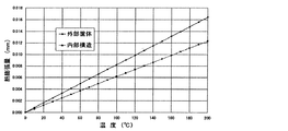
図3は、後部電極26と第1のインナーボディ32にこの別の材質のステンレス材を使用した場合に、外部筐体と内部構造体の熱膨張量が温度とともにどのように変化するかを計算して求めた結果を示す。圧電センサ22および後部電極26等の内部構造体の形状および配置は図1に示したものと同一である。
図3に示したグラフは、後部電極26と第1のインナーボディ32として上記の材料を使用した場合には、外部筐体と内部構造体との熱膨張量がマッチングし、温度が上昇しても熱膨張量の差が生じないことを示している。
FIG. 3 shows how the amount of thermal expansion of the outer casing and the inner structure changes with temperature when the other electrode stainless steel is used for the
The graph shown in FIG. 3 shows that when the above materials are used as the
図5は外部筐体と内部構造体との熱膨張量をマッチングさせた圧力センサを自動車用エンジンに取り付けて、図6に示す従来の圧力センサを使用した場合と同一の条件で燃焼圧を測定した結果を示す。図5においても、従来の圧力センサを用いた場合と同様に、エンジンの燃焼とともにスパイク状の出力信号が繰り返しあらわれている。この図5に示す測定データにおいて特徴的な点は、測定データの0点位置の変動がほとんどないことである。0点位置の変動については、図6に示す従来の圧力センサを用いた測定データと比較すると明りょうである。 FIG. 5 shows a case where a pressure sensor in which the thermal expansion amounts of the outer casing and the internal structure are matched is attached to an automobile engine, and the combustion pressure is measured under the same conditions as when the conventional pressure sensor shown in FIG. 6 is used. The results are shown. Also in FIG. 5, as in the case of using the conventional pressure sensor, spike-like output signals appear repeatedly with the combustion of the engine. A characteristic point in the measurement data shown in FIG. 5 is that there is almost no variation of the zero point position of the measurement data. The fluctuation of the zero point position is clear when compared with the measurement data using the conventional pressure sensor shown in FIG.
図6では、燃焼開始時から徐々に0点位置が下がっていく傾向がみられる。これはエンジンが燃焼開始するとともに圧力センサ自体の温度が徐々に上がっていき、外部筐体と内部構造体との熱膨張量の差が徐々に大きくなっていくことに対応している。一方、図5に示す本実施形態の圧力センサの測定データでは燃焼開始時からの時間経過とともに0点位置が変動する量はわずかである。これは外部筐体と内部構造体との熱膨張量がマッチングされていることによる。
図5、6を比較してわかるように、本実施形態の圧力センサによれば、0点位置の変動量を小さく抑えることによって、被測定体の圧力値を正確に測定することが可能になり、安定した信頼性の高い圧力センサとして使用することが可能となる。
In FIG. 6, there is a tendency that the 0 point position gradually decreases from the start of combustion. This corresponds to the fact that the temperature of the pressure sensor itself gradually increases with the start of combustion of the engine, and the difference in thermal expansion between the external housing and the internal structure gradually increases. On the other hand, in the measurement data of the pressure sensor of the present embodiment shown in FIG. 5, the amount by which the zero point position varies with the passage of time from the start of combustion is small. This is because the thermal expansion amounts of the outer casing and the inner structure are matched.
As can be seen by comparing FIGS. 5 and 6, according to the pressure sensor of the present embodiment, it is possible to accurately measure the pressure value of the object to be measured by suppressing the fluctuation amount of the zero point position to be small. Therefore, it can be used as a stable and reliable pressure sensor.
なお、上記実施形態においては、内部構造体のうち後部電極26と第1のインナーボディ32の材質を外部筐体である本体10の材質と異なる材質としたが、外部筐体と内部構造体との熱膨張量をマッチングさせる方法は、上記の方法に限られるものではない。たとえば、内部構造体を構成する他の部材の材質を変えるようにすることもできる。また、熱膨張量は各部材の物理的寸法にも関連するから、部材の大きさ(厚さ、長さ)を設計変更することによって調節することもできる。
In the above embodiment, the material of the
また、内部構造体の材質を変えるかわりに、外部筐体である本体10の材質を変えることによってマッチングを図ることも可能である。外部筐体と内部構造体との熱膨張量差は相対的なものであるから、外部筐体と内部構造体の一方あるいは双方についてその熱膨張量を比較検討して設計することができるからである。また、上述した実施形態のようにステンレス材であっても熱膨張係数が異なる材料を使用するといったように、同一材からなる材料であっても熱膨張係数が異なる材料を組み合わせて外部筐体と内部構造体との熱膨張量をマッチングさせるように調節することも可能である。
Further, instead of changing the material of the internal structure, it is possible to achieve matching by changing the material of the
本発明は上記実施形態において説明した構成に係る圧力センサに限ることなく、外部筐体内に圧電センサを備えた内部構造体を備え、圧電センサから信号を取り出すように構成されている圧力センサについては共通に適用することができる。この場合、圧力センサは圧電センサに対して常に一定の圧力を作用させる構造となっている製品に限るものではない。導電性接合剤等を使用して圧電センサに予圧を作用させることなく確実に電荷信号を取り出すことができる構造を備えた圧力センサについても同様に適用することができる。また、上記実施形態においてはランガサイト結晶からなる横軸効果を利用した圧電素子を用いて圧電センサ22としているが、他の圧電素子を使用した圧力センサについても同様に適用することができる。また、他の圧電素子を使用して上記実施形態とは異なる形態に構成した圧力センサについても同様に適用することができる。
The present invention is not limited to the pressure sensor according to the configuration described in the above embodiment, and the pressure sensor is configured to include an internal structure including a piezoelectric sensor in an external housing and extract a signal from the piezoelectric sensor. Can be applied in common. In this case, the pressure sensor is not limited to a product having a structure in which a constant pressure is always applied to the piezoelectric sensor. The present invention can be similarly applied to a pressure sensor having a structure that can reliably extract a charge signal without applying a preload to the piezoelectric sensor using a conductive bonding agent or the like. Moreover, in the said embodiment, although it is set as the
10 本体
15 ヘッド部
20 ダイアフラム
22 圧電センサ
24 前部電極
26 後部電極
28 絶縁リング
30 絶縁スリーブ
32 第1のインナーボディ
34 第2のインナーボディ
36 レーザ溶接部
40 リードピン
DESCRIPTION OF
Claims (4)
前記内部構造体が、圧電センサを挟んで配置された前部電極と後部電極とを備え、
前記圧電センサの熱膨張係数が前記外部筐体の熱膨張係数よりも小さく、前記後部電極
の熱膨張係数が前記外部筐体の熱膨張係よりも大きく設定され、前記外部筐体と前記内部構造体との熱膨張量がマッチングされて、前記圧電センサに作用する予圧力の変動を防止したことを特徴とする圧力センサ。 In a pressure sensor comprising: an external housing incorporating a piezoelectric sensor; and an internal structure including the piezoelectric sensor, which is disposed in the external housing and transmits pressure from a measurement object to the piezoelectric sensor.
The internal structure includes a front electrode and a rear electrode arranged with a piezoelectric sensor interposed therebetween,
A thermal expansion coefficient of the piezoelectric sensor is smaller than a thermal expansion coefficient of the outer casing;
The thermal expansion coefficient of the external housing is set to be larger than that of the external housing , and the amount of thermal expansion between the external housing and the internal structure is matched, so that the fluctuation of the pre-pressure acting on the piezoelectric sensor is reduced. A pressure sensor characterized by prevention.
前記内部構造体が圧電センサを挟んで配置された前部電極および後部電極と、該後部電極の後部に配置され、絶縁リングを介して前記圧電センサに予圧を加えた状態で前記外部筐体に固定された第1のインナーボディとを備え、
前記圧電センサと前記絶縁リングの熱膨張係数が前記外部筐体の熱膨張係数よりも小さく、前記後部電極と前記第1のインナーボディの熱膨張係数が前記外部筐体の熱膨張係数よりも大きく設定されて、前記外部筐体と前記内部構造体との熱膨張量がマッチングされて、前記圧電センサに作用する予圧力の変動を防止したことを特徴とする圧カセンサ。 In a pressure sensor comprising: an external housing incorporating a piezoelectric sensor; and an internal structure including the piezoelectric sensor, which is disposed in the external housing and transmits pressure from a measurement object to the piezoelectric sensor.
A front electrode and a rear electrode disposed with the internal structure sandwiching the piezoelectric sensor, and a rear portion of the rear electrode, and a preload is applied to the piezoelectric sensor via an insulating ring. A fixed first inner body,
The thermal expansion coefficient of the piezoelectric sensor and the insulating ring is smaller than the thermal expansion coefficient of the outer casing, and the thermal expansion coefficient of the rear electrode and the first inner body is larger than the thermal expansion coefficient of the outer casing. is set, the external housing and the thermal expansion amount of the internal structure is matched, pressure Kasensa characterized in that to prevent fluctuations in the preload force acting on the piezoelectric sensor.
前記圧電センサが前記ダイアフラムの後部に設けられた前部電極と前記後部電極とに挟まれて配置されていることを特徴とする請求項1または2記載の圧力センサ。 A diaphragm is formed integrally with the front electrode and sealed at the front end of the outer casing,
The pressure sensor according to claim 1 or 2, wherein the piezoelectric sensor is disposed between a front electrode and a rear electrode provided at a rear portion of the diaphragm .
Priority Applications (1)
| Application Number | Priority Date | Filing Date | Title |
|---|---|---|---|
| JP2004032996A JP3993857B2 (en) | 2004-02-10 | 2004-02-10 | Pressure sensor |
Applications Claiming Priority (1)
| Application Number | Priority Date | Filing Date | Title |
|---|---|---|---|
| JP2004032996A JP3993857B2 (en) | 2004-02-10 | 2004-02-10 | Pressure sensor |
Publications (3)
| Publication Number | Publication Date |
|---|---|
| JP2005227001A JP2005227001A (en) | 2005-08-25 |
| JP2005227001A5 JP2005227001A5 (en) | 2007-03-15 |
| JP3993857B2 true JP3993857B2 (en) | 2007-10-17 |
Family
ID=35001843
Family Applications (1)
| Application Number | Title | Priority Date | Filing Date |
|---|---|---|---|
| JP2004032996A Expired - Lifetime JP3993857B2 (en) | 2004-02-10 | 2004-02-10 | Pressure sensor |
Country Status (1)
| Country | Link |
|---|---|
| JP (1) | JP3993857B2 (en) |
Cited By (3)
| Publication number | Priority date | Publication date | Assignee | Title |
|---|---|---|---|---|
| JP2013205307A (en) * | 2012-03-29 | 2013-10-07 | Citizen Finetech Miyota Co Ltd | Pressure detector and internal combustion engine with the same |
| JP2014048181A (en) * | 2012-08-31 | 2014-03-17 | Citizen Finetech Miyota Co Ltd | Combustion pressure sensor |
| JP2014048045A (en) * | 2012-08-29 | 2014-03-17 | Citizen Finetech Miyota Co Ltd | Combustion pressure sensor |
Families Citing this family (4)
| Publication number | Priority date | Publication date | Assignee | Title |
|---|---|---|---|---|
| EP1842072B1 (en) * | 2005-01-26 | 2010-04-28 | Kistler Holding AG | Ground insulated piezoelectric sensor for the measurement of acceleration or pressure |
| DE102006008351A1 (en) | 2006-02-21 | 2007-08-23 | Robert Bosch Gmbh | Pressure measuring device for arrangement in chamber of internal combustion engine, has housing and ends of sensor cage are connected to force transmission unit and fixing unit |
| JP5161121B2 (en) * | 2008-03-28 | 2013-03-13 | 日本特殊陶業株式会社 | Glow plug |
| CN102288355B (en) * | 2011-07-16 | 2013-05-22 | 中北大学 | High-temperature pressure sensor |
-
2004
- 2004-02-10 JP JP2004032996A patent/JP3993857B2/en not_active Expired - Lifetime
Cited By (3)
| Publication number | Priority date | Publication date | Assignee | Title |
|---|---|---|---|---|
| JP2013205307A (en) * | 2012-03-29 | 2013-10-07 | Citizen Finetech Miyota Co Ltd | Pressure detector and internal combustion engine with the same |
| JP2014048045A (en) * | 2012-08-29 | 2014-03-17 | Citizen Finetech Miyota Co Ltd | Combustion pressure sensor |
| JP2014048181A (en) * | 2012-08-31 | 2014-03-17 | Citizen Finetech Miyota Co Ltd | Combustion pressure sensor |
Also Published As
| Publication number | Publication date |
|---|---|
| JP2005227001A (en) | 2005-08-25 |
Similar Documents
| Publication | Publication Date | Title |
|---|---|---|
| JP5748257B2 (en) | High-temperature pressure sensor element for measuring the internal pressure of the engine, its manufacturing method, and engine parts | |
| US9291512B2 (en) | Sensor for measuring pressure and/or force | |
| RU2504720C2 (en) | Ignition plug with pressure measurement version | |
| JP2010008416A (en) | Piezoresistive pressure measuring plug for combustion engine | |
| JP2006084468A (en) | Pressure measuring glow plug | |
| JP3993857B2 (en) | Pressure sensor | |
| JP2016205842A (en) | Pressure sensor | |
| KR0184012B1 (en) | Pressure sensor for determination of the pressure in the combustion space of an internal-combustion engine | |
| EP2060891A1 (en) | Infrared sensor comprising a Golay cell | |
| US8281665B2 (en) | Pressure sensor assembly | |
| JP5184052B2 (en) | Combustion pressure sensor | |
| JP6231984B2 (en) | Combustion pressure sensor | |
| EP3994437B1 (en) | Dual pressure sensor | |
| EP3690405B1 (en) | Sensor for measuring a first physical quantity, the measurement of which is influenced by a second physical quantity | |
| JP3873040B2 (en) | Pressure sensor | |
| WO2014010246A1 (en) | Combustion sensor | |
| JP2732433B2 (en) | Pressure sensor | |
| JP2004264037A (en) | Pressure sensor | |
| JP2005227001A5 (en) | ||
| JP2007198618A (en) | Glow plug with combustion pressure sensor | |
| US9618414B2 (en) | Device for determining a pressure and method for manufacturing the same | |
| JP2007198169A (en) | Combustion pressure sensor and internal combustion engine with sensor | |
| JP2009150325A (en) | Combustion pressure sensor | |
| JP3427667B2 (en) | Pressure sensor | |
| US10996120B1 (en) | Pressure sensor |
Legal Events
| Date | Code | Title | Description |
|---|---|---|---|
| A521 | Written amendment |
Free format text: JAPANESE INTERMEDIATE CODE: A523 Effective date: 20070126 |
|
| A621 | Written request for application examination |
Free format text: JAPANESE INTERMEDIATE CODE: A621 Effective date: 20070126 |
|
| A871 | Explanation of circumstances concerning accelerated examination |
Free format text: JAPANESE INTERMEDIATE CODE: A871 Effective date: 20070330 |
|
| A131 | Notification of reasons for refusal |
Free format text: JAPANESE INTERMEDIATE CODE: A131 Effective date: 20070508 |
|
| A521 | Written amendment |
Free format text: JAPANESE INTERMEDIATE CODE: A523 Effective date: 20070524 |
|
| TRDD | Decision of grant or rejection written | ||
| A01 | Written decision to grant a patent or to grant a registration (utility model) |
Free format text: JAPANESE INTERMEDIATE CODE: A01 Effective date: 20070626 |
|
| A975 | Report on accelerated examination |
Free format text: JAPANESE INTERMEDIATE CODE: A971005 Effective date: 20070406 |
|
| A61 | First payment of annual fees (during grant procedure) |
Free format text: JAPANESE INTERMEDIATE CODE: A61 Effective date: 20070727 |
|
| R150 | Certificate of patent or registration of utility model |
Ref document number: 3993857 Country of ref document: JP Free format text: JAPANESE INTERMEDIATE CODE: R150 Free format text: JAPANESE INTERMEDIATE CODE: R150 |
|
| FPAY | Renewal fee payment (event date is renewal date of database) |
Free format text: PAYMENT UNTIL: 20100803 Year of fee payment: 3 |
|
| FPAY | Renewal fee payment (event date is renewal date of database) |
Free format text: PAYMENT UNTIL: 20100803 Year of fee payment: 3 |
|
| S111 | Request for change of ownership or part of ownership |
Free format text: JAPANESE INTERMEDIATE CODE: R313111 |
|
| FPAY | Renewal fee payment (event date is renewal date of database) |
Free format text: PAYMENT UNTIL: 20100803 Year of fee payment: 3 |
|
| S111 | Request for change of ownership or part of ownership |
Free format text: JAPANESE INTERMEDIATE CODE: R313111 |
|
| FPAY | Renewal fee payment (event date is renewal date of database) |
Free format text: PAYMENT UNTIL: 20100803 Year of fee payment: 3 |
|
| R360 | Written notification for declining of transfer of rights |
Free format text: JAPANESE INTERMEDIATE CODE: R360 |
|
| FPAY | Renewal fee payment (event date is renewal date of database) |
Free format text: PAYMENT UNTIL: 20100803 Year of fee payment: 3 |
|
| R370 | Written measure of declining of transfer procedure |
Free format text: JAPANESE INTERMEDIATE CODE: R370 |
|
| FPAY | Renewal fee payment (event date is renewal date of database) |
Free format text: PAYMENT UNTIL: 20100803 Year of fee payment: 3 |
|
| R350 | Written notification of registration of transfer |
Free format text: JAPANESE INTERMEDIATE CODE: R350 |
|
| FPAY | Renewal fee payment (event date is renewal date of database) |
Free format text: PAYMENT UNTIL: 20100803 Year of fee payment: 3 |
|
| FPAY | Renewal fee payment (event date is renewal date of database) |
Free format text: PAYMENT UNTIL: 20110803 Year of fee payment: 4 |
|
| R250 | Receipt of annual fees |
Free format text: JAPANESE INTERMEDIATE CODE: R250 |
|
| FPAY | Renewal fee payment (event date is renewal date of database) |
Free format text: PAYMENT UNTIL: 20110803 Year of fee payment: 4 |
|
| FPAY | Renewal fee payment (event date is renewal date of database) |
Free format text: PAYMENT UNTIL: 20120803 Year of fee payment: 5 |
|
| R250 | Receipt of annual fees |
Free format text: JAPANESE INTERMEDIATE CODE: R250 |
|
| FPAY | Renewal fee payment (event date is renewal date of database) |
Free format text: PAYMENT UNTIL: 20120803 Year of fee payment: 5 |
|
| FPAY | Renewal fee payment (event date is renewal date of database) |
Free format text: PAYMENT UNTIL: 20130803 Year of fee payment: 6 |
|
| R250 | Receipt of annual fees |
Free format text: JAPANESE INTERMEDIATE CODE: R250 |
|
| R250 | Receipt of annual fees |
Free format text: JAPANESE INTERMEDIATE CODE: R250 |
|
| R250 | Receipt of annual fees |
Free format text: JAPANESE INTERMEDIATE CODE: R250 |
|
| R250 | Receipt of annual fees |
Free format text: JAPANESE INTERMEDIATE CODE: R250 |
|
| S531 | Written request for registration of change of domicile |
Free format text: JAPANESE INTERMEDIATE CODE: R313531 |
|
| S533 | Written request for registration of change of name |
Free format text: JAPANESE INTERMEDIATE CODE: R313533 |
|
| R350 | Written notification of registration of transfer |
Free format text: JAPANESE INTERMEDIATE CODE: R350 |
|
| R250 | Receipt of annual fees |
Free format text: JAPANESE INTERMEDIATE CODE: R250 |
|
| R250 | Receipt of annual fees |
Free format text: JAPANESE INTERMEDIATE CODE: R250 |
|
| R250 | Receipt of annual fees |
Free format text: JAPANESE INTERMEDIATE CODE: R250 |
|
| R250 | Receipt of annual fees |
Free format text: JAPANESE INTERMEDIATE CODE: R250 |
|
| R250 | Receipt of annual fees |
Free format text: JAPANESE INTERMEDIATE CODE: R250 |
|
| R250 | Receipt of annual fees |
Free format text: JAPANESE INTERMEDIATE CODE: R250 |
|
| R250 | Receipt of annual fees |
Free format text: JAPANESE INTERMEDIATE CODE: R250 |