JP3993824B2 - Low current consumption tire pressure monitoring system - Google Patents
Low current consumption tire pressure monitoring system Download PDFInfo
- Publication number
- JP3993824B2 JP3993824B2 JP2002537572A JP2002537572A JP3993824B2 JP 3993824 B2 JP3993824 B2 JP 3993824B2 JP 2002537572 A JP2002537572 A JP 2002537572A JP 2002537572 A JP2002537572 A JP 2002537572A JP 3993824 B2 JP3993824 B2 JP 3993824B2
- Authority
- JP
- Japan
- Prior art keywords
- mode
- pressure
- detector
- monitoring system
- vehicle
- Prior art date
- Legal status (The legal status is an assumption and is not a legal conclusion. Google has not performed a legal analysis and makes no representation as to the accuracy of the status listed.)
- Expired - Fee Related
Links
Images


Classifications
-
- B—PERFORMING OPERATIONS; TRANSPORTING
- B60—VEHICLES IN GENERAL
- B60C—VEHICLE TYRES; TYRE INFLATION; TYRE CHANGING; CONNECTING VALVES TO INFLATABLE ELASTIC BODIES IN GENERAL; DEVICES OR ARRANGEMENTS RELATED TO TYRES
- B60C23/00—Devices for measuring, signalling, controlling, or distributing tyre pressure or temperature, specially adapted for mounting on vehicles; Arrangement of tyre inflating devices on vehicles, e.g. of pumps or of tanks; Tyre cooling arrangements
- B60C23/02—Signalling devices actuated by tyre pressure
- B60C23/04—Signalling devices actuated by tyre pressure mounted on the wheel or tyre
- B60C23/0408—Signalling devices actuated by tyre pressure mounted on the wheel or tyre transmitting the signals by non-mechanical means from the wheel or tyre to a vehicle body mounted receiver
- B60C23/0422—Signalling devices actuated by tyre pressure mounted on the wheel or tyre transmitting the signals by non-mechanical means from the wheel or tyre to a vehicle body mounted receiver characterised by the type of signal transmission means
- B60C23/0433—Radio signals
- B60C23/0447—Wheel or tyre mounted circuits
- B60C23/0454—Means for changing operation mode, e.g. sleep mode, factory mode or energy save mode
-
- B—PERFORMING OPERATIONS; TRANSPORTING
- B60—VEHICLES IN GENERAL
- B60C—VEHICLE TYRES; TYRE INFLATION; TYRE CHANGING; CONNECTING VALVES TO INFLATABLE ELASTIC BODIES IN GENERAL; DEVICES OR ARRANGEMENTS RELATED TO TYRES
- B60C23/00—Devices for measuring, signalling, controlling, or distributing tyre pressure or temperature, specially adapted for mounting on vehicles; Arrangement of tyre inflating devices on vehicles, e.g. of pumps or of tanks; Tyre cooling arrangements
- B60C23/02—Signalling devices actuated by tyre pressure
- B60C23/04—Signalling devices actuated by tyre pressure mounted on the wheel or tyre
- B60C23/0408—Signalling devices actuated by tyre pressure mounted on the wheel or tyre transmitting the signals by non-mechanical means from the wheel or tyre to a vehicle body mounted receiver
- B60C23/0474—Measurement control, e.g. setting measurement rate or calibrating of sensors; Further processing of measured values, e.g. filtering, compensating or slope monitoring
- B60C23/0477—Evaluating waveform of pressure readings
Abstract
Description
【0001】
(技術分野)
本発明は、低電流消費のタイヤ圧力モニタリングシステムに関する。
【0002】
(背景技術)
自動車およびタイヤの製造業者は、安全性、快適性および利便性に対する現代の道路ユーザの常時増大する要望に注意を払うことを熱心に試みている。この現象は、例えばエアバッグ、ABSブレーキ、ESP装置等のように、つい数年前には事実上存在しなかった種々の形式の装置の当たり前の性質からも明白である。最近では、タイヤ圧力測定および/またはモニタリング装置を入手できるようになった。車両のタイヤの膨張度合いを、簡単に、信頼性をもって定期的に運転者に知らせることにより、安全性、燃費、タイヤの稼動寿命等を改善できる。このようなシステムは、一般に、それ自体は既知の形式の少なくとも1つの圧力センサを有している。
【0003】
かくして、所与の時点でタイヤの圧力を測定できる或る形式(例えば容量形または抵抗形)の圧力センサは知られている。一般にこのようなセンサは、測定を行ないかつ収集した情報を伝送するための電気的供給を必要とする。ホイールに電池を設けることも知られている。圧力測定を頻繁にまたは連続的に行なうこと(このことは、例えばタイヤのパンクの検出を望む場合には不可避である)を望む場合には、電池を容易に交換できなくてはならない。なぜならば、センサは電池に大きい負荷を課し、電池が早急に放電されてしまうからである。したがって、簡単、迅速かつ安価な態様で交換できなくてはならない。
このような状況では、最も苛酷な環境に耐えなくてはならない電池の接点のため、定常的に信頼性の問題に遭遇する。接点は劣化するため、電気エネルギの供給が途切れまたは不安定になり、或いは完全に遮断されてしまう危険がある。
【0004】
この種の状況を改善するため、交換不可能な電池が使用されており、この電池は例えば溶接により最終的な態様で電気回路内に組込まれている。これにより、一層信頼できるエネルギ供給が達成される。他方で、電池の稼動寿命が短くなり過ぎることを防止したい場合には、圧力モニタリングシステムへの電力の連続的供給を回避して、電池の利用できるエネルギの過度に急速な消費を回避することが強く望まれる。従って、センサを連続的に作動させるのではなく、真に必要とするときにのみ作動できるようにする種々の手段が研究されている。かくして、車両が停止しているときは、連続測定を行なう意味はない。この問題の既知の1つの解決法は、車両が停止しているときはセンサを遮断する遠心スイッチを使用することである。例えばばね押圧ボールのような遠心スイッチは、車両の状況(車両が移動しているか、停止しているか)を検出するのに現在使用されている。例えば、約3〜5km/hの速度での数秒間に亘る走行は、センサの再付勢を可能にする。しかしながら、この形式のスイッチには幾つかの制限がある。実際に、遠心スイッチは高価であり、耐久性が低く、非常に正確であるとはいえない。このため、通常の測定モードが再開される前に200〜300m以上走行することがしばしば必要になる。このような場合、運転者が、一旦駐車場に入れ再び公道を走行するときは、圧力不足またはパンクの場合でも警告を受ける蓋然性がある。この種の状況を防止することが強く望まれていることは明白である。
【0005】
(発明の開示)
本発明の目的は、上記問題を改善することにある。上記目的を達成するため、本発明によれば、
タイヤの周囲圧力と流体連通している圧力測定センサと、
車両が始動されたときに発生されるノイズを検出できるノイズ検出器と、
管理モジュールとを有し、該管理モジュールは、一方では圧力センサによりかつ他方ではノイズ検出器により供給されるデータを受けて、車両が停止しているときには圧力センサが「エコノミー」モードで作動し、車両が移動しているときは圧力センサが「通常」モードで作動するように前記データを処理することを特徴とするタイヤ圧力モニタリングシステムが提供される。
【0006】
ここで、「ノイズ」とは、音響振動を意味する。ノイズ検出器により、上記遠心スイッチをなくすことができる。例えば、10〜100Hz以上の周波数のみを保有できるようにするため、システムに高域通過フィルタを設けることが好ましい。
このノイズ検出器は圧電形検出器が好ましい。
【0007】
これは、これ自体が試行錯誤されかつ試験された信頼性のある正確な技術であり、例えば100ms以下の非常に短い応答時間が得られる。また、圧電形センサの主要な特徴の1つは、該圧電形センサが、電力の供給なくして作動できることである。より詳しくは、圧電形材料からなる膜の変形により、微小電流が発生されることである。この電流は次に、信号を読取り、処理しまたは分析する回路に使用される。電子モジュールのみが電力の供給を必要とするが、非常に小さい電力で済む。従って、長寿命電池が得られる。
【0008】
ノイズ検出器は、圧力変化検出器でもあることが有利である。
例えばブローアウト検出器として機能するか、圧力測定センサの反復速度を制御する、圧力変化の検出に関連する機能に加え、圧電形の圧力変化センサは、走行モードへの変換を高精度で容易に検出するマイクロホンとして機能する。この場合には、あらゆる異常性の検出を非常に迅速に行なうことができ、運転者は、そのことを、駐車場を出る充分前に、実際には走行モードに入る前にも知らされる。なぜならば、エンジンの始動でさえも圧電形検出器により検出されるため、運転者車両が移動する前でも対応できるからである。本発明の有利な一実施形態によれば、圧電形検出器の電力消費は実質的にゼロであり、これにより、電池のエネルギが節約される。
【0009】
有利な一例では、ノイズ検出器は、該検出器が関連するホイールの角度変位により発生されるノイズに感応する。
他の有利な例では、ノイズ検出器は、車両のエンジンにより発生されるノイズに感応する。
【0010】
「エコノミー」モードは、圧力センサにより行なわれる測定間の時間間隔が「通常」モードより実質的に長いモードであることが好ましい。
「エコノミー」モードでは、タイヤ圧力を測定する周波数を低下させることができる。この場合、モニタリングシステムには、2、3、5、30、60、120分毎等の時間間隔のみに電力が供給される。走行が再開されると、「通常」測定モードが再び選択される。
【0011】
本発明の有利な一実施形態によれば、作動モードが「エコノミー」モードから「通常」モードに変化するときに、「加速」測定モードで作動する遷移時間が付与され、「加速」測定モードでは、圧力センサにより行なわれる測定間の時間間隔が「通常」モードより実質的に短い。
【0012】
本発明のタイヤ圧力モニタリングシステムは、センサおよび検出器が有利に配置されているホイールから、車両の非回転部分にデータを伝送でき、この伝送手段には、1つ以上のアンテナを設けるのが好ましい。
伝送手段はトランスポンダ形に構成でき、実際には無線エミッタ/受信器形に構成できる。
【0013】
装置が応答するために望まれる時間間隔は、例えば、時間が0秒に近い時間間隔のような非常に短い時間に一致する。この時間が短いほど、装置は安全性の向上に寄与できる。
【0014】
管理モジュールにより伝送される信号は、電気または無線形式であるのが有利である。
例えば、圧力変化検出器はケーシングを有し、該ケーシングには、互いに実質的に絶縁されかつ圧電形の変形可能膜により分離された2つのチャンバが設けられ、第一チャンバは基準圧力を受け、第二チャンバはモニタリングを行なうことを望む媒体の環境と流体連通でき、前記膜は前記環境の圧力変化の作用を受けて変形でき、この変形により電気信号を発生でき、該電気信号の強度は変形の度合いに関係している。
【0015】
基準チャンバの基準圧力は実質的に一定であり、モニタリングされる環境の圧力変化時には変化しない。これにより、両チャンバ間の圧力差が変化でき、この変化により圧電形信号が発生される。
【0016】
有利なことは、膜が、圧力変化のレベルおよび/または速度に関係する変形の大きさおよび/または速度に応答できることである。
また、有利なことは基準圧力が真空に一致することである。
【0017】
センサは、モニタリングが行なわれる媒体の環境がタイヤキャビティ内の圧力に一致する態様で配置するのが有利である。例えば、センサは前記キャビティ内に直接配置できる。一方、例えばパイプを使用して、環境を、ホイール内に配置されたセンサに向けることができる。
【0018】
本発明による装置はホイールに取付けるのが有利である。この場合には、信号がホイールから車両に確実に導かれるように、データを伝送するための少なくとも1つの手段を車両の非回転部分に設けるのが有利である。車両は少なくとも1つのデータ受信手段を呈する。
本発明はまた、上記ノイズ検出器を備えたタイヤを提供する。
本発明はまた、上記ノイズ検出器を備えたリムを提供する。
【0019】
(発明を実施するための最良の形態)
本発明の他の特徴および長所は、添付図面を参照して述べる本発明によるブローアウト検出装置についての以下の非制限的説明を読むことにより明らかになるであろう。
【0020】
図4には、本発明によるタイヤの圧力をモニタリングするシステム1の機能図が示されている。モニタリングシステム1は、後述のように、圧力センサ7および圧力変化センサ2を有する。センサ2と電気的および機械的に協働する管理モジュール3が設けられている。電池4は、モジュール3およびセンサ7に電力を供給でき、センサ2に供給することも任意である。しかしながら、本発明による幾つかの有利な形式のセンサ2はいかなる電力の供給も必要とせず、従って電池4に関する節約が可能である。データを車両のホイールから車両に伝送できるようにするために、伝送モジュール5を設けるのが好ましくかつ有利である。伝送モジュール5は、例えばエミッタ(好ましくはHFエミッタ)、トランスポンダ等で構成できる。任意であるが、アンテナ6を設けることにより図4の装置が完成される。
【0021】
この装置は、ホイール、すなわちリムまたはタイヤのいずれかに取付けるためのものである。装置はまた、例えばタイヤの壁に成形されたようなこれらの要素一方または他方に組込むこともできる。この理由から、圧力変化検出器2は電力供給を必要としないものを使用するのが好ましく、これにより、電池4が、タイヤ、ホイールまたは車両の寿命にできる限り一致する寿命を呈するようにすることができる。この場合には、電池4は、例えば溶接により装置1内に組込むことができる。この態様により、交換可能な電池に特有の接点の問題が回避される。
【0022】
図1には、特に有利な形式の圧電形の圧力変化検出器2が示されている。この検出器2はケーシング25を有し、該ケーシング25には圧電形の膜23により互いに分離されかつ実質的に絶縁された2つのチャンバ21、22が設けられている。開口24は、検出器の第一チャンバ21と、モニタリングを望む媒体すなわち環境との間の流体連通の確立を可能にする。チャンバ22は基準圧力を受けるか、無圧すなわち真空であってもよい。電気出力28は、膜23の任意の変形の間に発生される弱い電流信号の伝送を可能にする。
【0023】
チャンバ22が真空であるならば、膜23は一般に凹状を呈する。すなわち、膜23は真空によりチャンバ22に向かって押される。オリフィス24から生じるあらゆる付加圧力は膜23の変形に寄与し、膜23は、例えば参照番号26で示すような安定位置を占めるであろう。制御チャンバ21内のあらゆる圧力降下により必然的に膜23が新しく変形し、これにより、膜23は元の(実質的に平らな)形状すなわちプロファイル27になろうとする傾向を有する。膜23の曲率が変化すると、変形の大きさおよび/または速度に関係して弱い電流が発生する。かくして、オリフィス21を介してチャンバ21に連結されたタイヤのブローアウトにより、必然的に、チャンバ21内に大きくて急激な圧力降下が生じる。第一安定プロファイルから第二安定プロファイルへの膜23の変形により、電気出力28により電流が発生される。この電流は、その後、管理モジュール3に入力されかつ適当に処理される。
【0024】
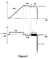
図2には、本発明による圧力変化検出器2により発生される信号の例を示す。この図面は、検出器2が呈する物理的現象と検出器の対応する信号との関係を示すものである。例えば膨張モードAでは、圧力が変化すなわち増大する。これにより信号が発生され、この信号は、例えば正でかつ一定であり、かつ僅かな連続的かつ規則的な圧力変化に関連している。
【0025】
符号B、Dで示す一定圧力では信号は全く発生されない。なぜならば、膜は固定された状態を維持し、プロファイルが変化しないからである。
符号Cで示す圧力降下の場合には、例えば負で一定の信号が、僅かで一定かつ規則的な圧力降下に関連して発生する。
符号Fで示す部分ではタイヤが破裂し、従って非常に大きくかつ急激な圧力損失を受け、短時間の「スパイク」の形態の信号が発生される。なぜならば、センサの膜が非常に短時間(時間とは、実質的な第一安定プロファイルから他の実質的な安定プロファイルに至るのに要する時間である)に大きく変形されるからである。
符号Eで示す部分では、圧力が安定しており、車両は移動を続けている。センサは、その感度に基いて走行ノイズをピックアップし、この場合には、ノイズ検出器すなわちセンサまたはマイクロフォンとして機能する。圧力変化検出器および走行ノイズ検出器としてのこの二重機能は、図3に示すように特に有利である。
【0026】
図3には、本発明による圧力モニタリングシステムを使用したタイヤモニタリング方法の作動図が示されている。通常機能モードでは、圧力センサ7による測定は、所与の時間間隔で反復して行なわれる。
【0027】
電池の稼動寿命をできる限り最大に延長するには、一般に、車両が停止(特に長時間停止)する場合のように、もはやタイヤを連続的にモニタリングする必要がなくなったときはできる限り早く、反復数を所与の時間減少させることが望まれる。この目的のため、ノイズ検出器2が、車両の音挙動、好ましくは1つ以上のタイヤの音挙動を連続的にモニタリングする。一般に、車両が停止しているときは、音レベルは消滅し、すなわち実質的にゼロになる。ノイズ検出器はこの状況を検出できる。次に、管理モジュール3は「エコノミー」モードを開始し、このモードでは、遂行される測定間の時間間隔が通常モードより実質的に長くなる。この作動形式は、特に、電池を節約することができる。ノイズ検出器がエンジンの作動ノイズを検出するように較正されている場合には、走行する前に必ず通常モードへの切換えが行なわれる。かくして、異常圧力に付随するいかなる問題も、車両が路上に出る前に検出される。検出器が、単にホイールの走行を検出するように較正されている場合には、このホイールの走行は、最初の角度変位が行なわれるやいなや検出され、従って、車両が路上に出て高速走行を開始する前に、あらゆる圧力問題を発見できる。
【0028】
作動モードが「エコノミー」モードから「通常」モードに切換えられるとき、「加速」測定モードで作動する短い遷移時間を付与するのが有利であり、これにより、1つ以上のタイヤの圧力のあらゆる異常性を非常に迅速に、すなわち事実上瞬間的に検出することが可能になる。
【図面の簡単な説明】
【図1】 本発明による圧力変化センサを示す概略断面図である。
【図2】 車両のタイヤに生じ易い或る形式の圧力変化に関連する信号の例を示すグラフである。
【図3】 本発明によるモニタリングシステムを備えたタイヤをモニタリングするためのフローチャートである。
【図4】 圧力センサおよび圧力変化検出器を備えた車両のタイヤの圧力測定および/またはモニタリングシステムの機能を示す図面である。[0001]
(Technical field)
The present invention relates to a tire pressure monitoring system with low current consumption.
[0002]
(Background technology)
Automobile and tire manufacturers are eager to pay attention to the ever-increasing demands of modern road users for safety, comfort and convenience. This phenomenon is also evident from the natural nature of various types of devices that did not exist virtually a few years ago, such as airbags, ABS brakes, ESP devices, and the like. Recently, tire pressure measurement and / or monitoring devices have become available. By simply informing the driver of the degree of expansion of the tires of the vehicle on a regular basis with reliability, safety, fuel efficiency, tire service life, etc. can be improved. Such systems generally have at least one pressure sensor of a type known per se.
[0003]
Thus, certain types of pressure sensors (eg, capacitive or resistive) that can measure tire pressure at a given time are known. In general, such sensors require an electrical supply to make measurements and transmit the collected information. It is also known to provide batteries on the wheels. If it is desired to make pressure measurements frequently or continuously (which is unavoidable if, for example, tire puncture detection is desired), the batteries must be easily replaceable. This is because the sensor imposes a large load on the battery and the battery is discharged quickly. Therefore, it must be replaceable in a simple, quick and inexpensive manner.
In such situations, reliability problems are constantly encountered due to battery contacts that must withstand the harshest environments. Since the contacts deteriorate, there is a risk that the supply of electrical energy is interrupted, becomes unstable, or is completely cut off.
[0004]
In order to improve this kind of situation, a non-replaceable battery is used, which is integrated into the electrical circuit in a final manner, for example by welding. Thereby, a more reliable energy supply is achieved. On the other hand, if you want to prevent the battery's operating life from becoming too short, you can avoid the continuous supply of power to the pressure monitoring system and avoid excessively rapid consumption of the battery's available energy. Strongly desired. Therefore, various means have been studied that allow the sensor to be activated only when it is really needed, rather than continuously. Thus, there is no point in making continuous measurements when the vehicle is stopped. One known solution to this problem is to use a centrifugal switch that shuts off the sensor when the vehicle is stationary. Centrifugal switches, such as spring-loaded balls, are currently used to detect vehicle conditions (whether the vehicle is moving or stopped). For example, running for several seconds at a speed of about 3-5 km / h allows the sensor to be re-energized. However, this type of switch has some limitations. In fact, centrifugal switches are expensive, have low durability and are not very accurate. For this reason, it is often necessary to travel 200 to 300 m or more before the normal measurement mode is resumed. In such a case, when the driver once enters the parking lot and travels on the public road again, there is a possibility that a warning is received even in the case of insufficient pressure or puncture. Clearly it is highly desirable to prevent this kind of situation.
[0005]
(Disclosure of the Invention)
An object of the present invention is to improve the above problems. In order to achieve the above object, according to the present invention,
A pressure measuring sensor in fluid communication with the ambient pressure of the tire;
A noise detector that can detect noise generated when the vehicle is started;
A management module, which receives data supplied on the one hand by a pressure sensor and on the other hand by a noise detector, so that the pressure sensor operates in "economy" mode when the vehicle is stationary, A tire pressure monitoring system is provided that processes the data such that the pressure sensor operates in a “normal” mode when the vehicle is moving.
[0006]
Here, “noise” means acoustic vibration. The centrifugal switch can be eliminated by the noise detector. For example, it is preferable to provide a high-pass filter in the system so that only a frequency of 10 to 100 Hz or higher can be retained.
This noise detector is preferably a piezoelectric detector.
[0007]
This is a reliable and accurate technique that has been trial-and-errored and tested in itself, resulting in very short response times of, for example, 100 ms or less. One of the main characteristics of the piezoelectric sensor is that the piezoelectric sensor can be operated without supplying power. More specifically, a minute current is generated by deformation of a film made of a piezoelectric material. This current is then used in a circuit that reads, processes or analyzes the signal. Only the electronic module needs power supply, but very little power is required. Therefore, a long-life battery is obtained.
[0008]
The noise detector is advantageously also a pressure change detector.
In addition to functions related to pressure change detection, for example functioning as a blowout detector or controlling the repetitive speed of the pressure measurement sensor, the piezoelectric pressure change sensor makes it easy to convert to driving mode with high accuracy Functions as a microphone to detect. In this case, any abnormalities can be detected very quickly, and the driver is informed well before leaving the parking lot and actually before entering the driving mode. This is because even the start of the engine is detected by the piezoelectric detector, and can be handled even before the driver's vehicle moves. According to an advantageous embodiment of the invention, the power consumption of the piezoelectric detector is substantially zero, which saves battery energy.
[0009]
In one advantageous example, the noise detector is sensitive to noise generated by the angular displacement of the wheel with which the detector is associated.
In another advantageous example, the noise detector is sensitive to noise generated by the vehicle engine.
[0010]
The “economy” mode is preferably a mode in which the time interval between measurements performed by the pressure sensor is substantially longer than the “normal” mode.
In the “economy” mode, the frequency at which tire pressure is measured can be reduced. In this case, power is supplied to the monitoring system only at time intervals such as every 2, 3, 5, 30, 60, 120 minutes. When travel is resumed, the “normal” measurement mode is selected again.
[0011]
According to an advantageous embodiment of the invention, when the operating mode changes from the “economy” mode to the “normal” mode, a transition time is provided to operate in the “accelerated” measurement mode, The time interval between measurements made by the pressure sensor is substantially shorter than in the “normal” mode.
[0012]
The tire pressure monitoring system of the present invention is capable of transmitting data to a non-rotating part of a vehicle from a wheel in which sensors and detectors are advantageously arranged, and this transmission means is preferably provided with one or more antennas. .
The transmission means can be configured as a transponder, and in practice can be configured as a wireless emitter / receiver.
[0013]
The time interval desired for the device to respond corresponds to a very short time, for example a time interval close to 0 seconds. The shorter this time, the more the device can contribute to safety.
[0014]
The signal transmitted by the management module is advantageously in electrical or wireless form.
For example, the pressure change detector has a casing that is provided with two chambers that are substantially insulated from each other and separated by a piezoelectric deformable membrane, the first chamber receives a reference pressure, The second chamber can be in fluid communication with the environment of the medium desired to be monitored, the membrane can be deformed under the effect of pressure changes in the environment, and the deformation can generate an electrical signal, the strength of the electrical signal being deformed. Is related to the degree.
[0015]
The reference pressure in the reference chamber is substantially constant and does not change when the pressure of the monitored environment changes. Thereby, the pressure difference between both chambers can be changed, and this change generates a piezoelectric signal.
[0016]
Advantageously, the membrane can respond to the magnitude and / or rate of deformation related to the level and / or rate of pressure change.
It is also advantageous that the reference pressure matches the vacuum.
[0017]
The sensor is advantageously arranged in such a way that the environment of the medium in which the monitoring takes place corresponds to the pressure in the tire cavity. For example, the sensor can be placed directly in the cavity. On the other hand, the environment can be directed to sensors located in the wheel, for example using pipes.
[0018]
The device according to the invention is advantageously mounted on a wheel. In this case, it is advantageous to provide at least one means for transmitting data in the non-rotating part of the vehicle in order to ensure that the signal is guided from the wheel to the vehicle. The vehicle presents at least one data receiving means.
The present invention also provides a tire including the noise detector.
The present invention also provides a rim equipped with the noise detector.
[0019]
(Best Mode for Carrying Out the Invention)
Other features and advantages of the present invention will become apparent upon reading the following non-limiting description of a blowout detection device according to the present invention described with reference to the accompanying drawings.
[0020]
FIG. 4 shows a functional diagram of a system 1 for monitoring tire pressure according to the present invention. The monitoring system 1 includes a
[0021]
This device is for mounting on a wheel, either a rim or a tire. The device can also be incorporated into one or the other of these elements, such as molded into a tire wall. For this reason, it is preferable to use a
[0022]
FIG. 1 shows a particularly advantageous type of piezoelectric
[0023]
If the
[0024]
FIG. 2 shows an example of a signal generated by the
[0025]
No signal is generated at the constant pressure indicated by the symbols B and D. This is because the membrane remains fixed and the profile does not change.
In the case of the pressure drop indicated by the symbol C, for example, a negative and constant signal is generated in connection with a slight, constant and regular pressure drop.
In the part indicated by the symbol F, the tire ruptures and therefore receives a very large and abrupt pressure loss, generating a signal in the form of a short “spike”. This is because the sensor membrane is greatly deformed in a very short time (time is the time required to reach from one substantial first stability profile to another substantial stability profile).
In the portion indicated by the symbol E, the pressure is stable and the vehicle continues to move. The sensor picks up driving noise based on its sensitivity and in this case functions as a noise detector or sensor or microphone. This dual function as a pressure change detector and a running noise detector is particularly advantageous as shown in FIG.
[0026]
FIG. 3 shows an operational diagram of a tire monitoring method using a pressure monitoring system according to the present invention. In the normal function mode, the measurement by the
[0027]
To extend the battery life to the maximum possible, it is generally repetitive as soon as possible when tires no longer need to be continuously monitored, such as when the vehicle stops (especially when it stops for a long time). It is desirable to reduce the number for a given time. For this purpose, the
[0028]
When the operating mode is switched from “economy” mode to “normal” mode, it is advantageous to provide a short transition time to operate in the “acceleration” measurement mode, thereby causing any abnormalities in the pressure of one or more tires. It becomes possible to detect sex very quickly, ie virtually instantaneously.
[Brief description of the drawings]
FIG. 1 is a schematic cross-sectional view showing a pressure change sensor according to the present invention.
FIG. 2 is a graph illustrating an example of a signal associated with some form of pressure change that is likely to occur in a vehicle tire.
FIG. 3 is a flowchart for monitoring a tire equipped with a monitoring system according to the present invention.
FIG. 4 is a diagram illustrating the function of a vehicle tire pressure measurement and / or monitoring system including a pressure sensor and a pressure change detector.
Claims (6)
車両が始動されたときに発生されるノイズを検出できるノイズ検出器と、
管理モジュールとを有し、該管理モジュールは、一方では圧力センサによりかつ他方ではノイズ検出器により供給されるデータを受けて、車両が停止しているときには圧力センサが「エコノミー」モードで作動し、車両が移動しているときは圧力センサが「通常」モードで作動するように前記データを処理し、
前記ノイズ検出器は圧力変化検出器であることを特徴とするタイヤ圧力モニタリングシステム。A pressure measuring sensor in fluid communication with the ambient pressure of the tire;
A noise detector that can detect noise generated when the vehicle is started;
A management module, which receives data supplied on the one hand by a pressure sensor and on the other hand by a noise detector, so that the pressure sensor operates in "economy" mode when the vehicle is stationary, Processing the data so that the pressure sensor operates in "normal" mode when the vehicle is moving,
The tire pressure monitoring system, wherein the noise detector is a pressure change detector.
Applications Claiming Priority (2)
| Application Number | Priority Date | Filing Date | Title |
|---|---|---|---|
| FR0013773A FR2815710A1 (en) | 2000-10-23 | 2000-10-23 | System for surveying motor vehicle tire pressure has both pressure and noise sensors operating in conjunction with a controller so that operating mode can be switched between economy and normal mode dependent on noise level |
| PCT/EP2001/012166 WO2002034553A1 (en) | 2000-10-23 | 2001-10-22 | Low-power consumption system for monitoring pressure in a tyre |
Publications (2)
| Publication Number | Publication Date |
|---|---|
| JP2004512216A JP2004512216A (en) | 2004-04-22 |
| JP3993824B2 true JP3993824B2 (en) | 2007-10-17 |
Family
ID=8855786
Family Applications (1)
| Application Number | Title | Priority Date | Filing Date |
|---|---|---|---|
| JP2002537572A Expired - Fee Related JP3993824B2 (en) | 2000-10-23 | 2001-10-22 | Low current consumption tire pressure monitoring system |
Country Status (11)
| Country | Link |
|---|---|
| US (1) | US6880394B2 (en) |
| EP (1) | EP1330372B1 (en) |
| JP (1) | JP3993824B2 (en) |
| KR (1) | KR20030036939A (en) |
| CN (1) | CN1257065C (en) |
| AT (1) | ATE274421T1 (en) |
| AU (1) | AU2002221712A1 (en) |
| CA (1) | CA2426361A1 (en) |
| DE (1) | DE60105187T2 (en) |
| FR (1) | FR2815710A1 (en) |
| WO (1) | WO2002034553A1 (en) |
Families Citing this family (27)
| Publication number | Priority date | Publication date | Assignee | Title |
|---|---|---|---|---|
| US8266465B2 (en) | 2000-07-26 | 2012-09-11 | Bridgestone Americas Tire Operation, LLC | System for conserving battery life in a battery operated device |
| US7161476B2 (en) | 2000-07-26 | 2007-01-09 | Bridgestone Firestone North American Tire, Llc | Electronic tire management system |
| US6892568B2 (en) * | 2003-02-03 | 2005-05-17 | Honda Giken Kogyo Kabushiki Kaisha | Noise detection system and method |
| JP3946109B2 (en) * | 2002-08-28 | 2007-07-18 | 横浜ゴム株式会社 | Tire pressure monitoring device and pneumatic tire equipped with the device |
| GB0222680D0 (en) * | 2002-10-01 | 2002-11-06 | Haswell Moulding Technologies | Power generation |
| GB0321104D0 (en) * | 2003-09-10 | 2003-10-08 | Schrader Electronics Ltd | Method and apparatus for detecting wheel motion in a tyre pressure monitoring system |
| FR2863205B1 (en) * | 2003-12-08 | 2006-02-17 | Michelin Soc Tech | PNEUMATIC INFLATION METHOD, DEVICE AND MACHINE FOR IMPLEMENTING THE METHOD |
| US7497114B2 (en) | 2004-04-29 | 2009-03-03 | Nxp B.V. | Tag used for monitoring the tire pressure |
| JP2006069413A (en) * | 2004-09-03 | 2006-03-16 | Denso Corp | Tire air pressure detecting device |
| JP2006329772A (en) * | 2005-05-25 | 2006-12-07 | Shinko Electric Ind Co Ltd | Power generator and tire air pressure alarm system provided with same |
| FR2905190B1 (en) * | 2006-08-25 | 2008-10-10 | Siemens Vdo Automotive Sas | METHOD AND DEVICE FOR IDENTIFYING WHEELS MOUNTED ON A MOTOR VEHICLE |
| FR2905189B1 (en) * | 2006-08-25 | 2010-04-16 | Siemens Vdo Automotive | METHOD AND DEVICE FOR LOCATING THE LONGITUDINAL POSITION OF WHEELS OF A VEHICLE |
| US7498931B2 (en) * | 2006-08-28 | 2009-03-03 | Lear Corporation | Tire pressure monitoring system |
| US7741964B2 (en) * | 2007-05-31 | 2010-06-22 | Schrader Electronics Ltd. | Tire pressure detector having reduced power consumption mechanism |
| KR100863101B1 (en) * | 2007-08-14 | 2008-10-13 | 현대자동차주식회사 | Method for alarming external noise signal in tpms system |
| FR2924982B1 (en) * | 2007-12-14 | 2009-12-25 | Siemens Vdo Automotive | METHOD FOR LOCATING THE LONGITUDINAL POSITION OF WHEELS OF A VEHICLE |
| CN101492000B (en) * | 2008-01-22 | 2010-12-08 | 苏州驶安特汽车电子有限公司 | Tire pressure real-time monitoring method using tire pressure monitoring system |
| DE102008021466A1 (en) * | 2008-04-29 | 2009-11-12 | Beru Ag | Method, system and system components for wireless tire pressure monitoring |
| US8072321B2 (en) * | 2008-10-29 | 2011-12-06 | Schrader Electronics. Ltd. | Tire pressure sensing devices, systems and methods employing an acoustic amplifier |
| WO2012091719A1 (en) * | 2010-12-30 | 2012-07-05 | Michelin Recherche Et Technique, S.A. | Piezoelectric based system and method for determining tire load |
| FR3045498B1 (en) * | 2015-12-18 | 2017-12-22 | Continental Automotive France | METHOD FOR ADAPTING THE STRATEGY FOR ACQUIRING RADIATION ACCELERATION MEASUREMENTS OF WHEELS OF A VEHICLE |
| DE102016211047B3 (en) * | 2016-06-21 | 2017-10-19 | Continental Automotive Gmbh | Electronic wheel unit for a vehicle wheel |
| CN106143010B (en) * | 2016-08-31 | 2017-11-24 | 李曙光 | A kind of motion state of automobile without acceleration transducer monitors integrated circuit |
| WO2019127505A1 (en) * | 2017-12-29 | 2019-07-04 | 深圳配天智能技术研究院有限公司 | Tyre and vehicle |
| DE102018103121A1 (en) * | 2018-02-13 | 2019-08-14 | Inventus Engineering Gmbh | Vehicle component and method |
| CN108556570B (en) * | 2018-04-23 | 2020-07-10 | 重庆长安汽车股份有限公司 | Tyre prick nail discriminating device and method |
| CN112606636A (en) * | 2021-02-01 | 2021-04-06 | 桂林电子科技大学 | Passive monitoring system of automobile tire |
Family Cites Families (3)
| Publication number | Priority date | Publication date | Assignee | Title |
|---|---|---|---|---|
| DE19917360A1 (en) * | 1999-04-16 | 2000-10-19 | Tomalla Jutta | Tire damage detection system for cars uses acoustic sensors in the wheel rims |
| US6580364B1 (en) * | 2000-07-06 | 2003-06-17 | Trw Inc. | Apparatus and method for tracking an abnormal tire condition |
| US20030136192A1 (en) * | 2002-01-23 | 2003-07-24 | Jia-Heng Tu | System and method for detecting noises and sounds in wheels, tires and bearings of a vehicle |
-
2000
- 2000-10-23 FR FR0013773A patent/FR2815710A1/en active Pending
-
2001
- 2001-10-22 WO PCT/EP2001/012166 patent/WO2002034553A1/en active IP Right Grant
- 2001-10-22 CN CNB018193684A patent/CN1257065C/en not_active Expired - Fee Related
- 2001-10-22 DE DE60105187T patent/DE60105187T2/en not_active Expired - Lifetime
- 2001-10-22 EP EP01988659A patent/EP1330372B1/en not_active Expired - Lifetime
- 2001-10-22 JP JP2002537572A patent/JP3993824B2/en not_active Expired - Fee Related
- 2001-10-22 CA CA002426361A patent/CA2426361A1/en not_active Abandoned
- 2001-10-22 AU AU2002221712A patent/AU2002221712A1/en not_active Abandoned
- 2001-10-22 AT AT01988659T patent/ATE274421T1/en not_active IP Right Cessation
- 2001-10-22 KR KR10-2003-7005543A patent/KR20030036939A/en not_active Application Discontinuation
-
2003
- 2003-04-17 US US10/417,575 patent/US6880394B2/en not_active Expired - Lifetime
Also Published As
| Publication number | Publication date |
|---|---|
| DE60105187D1 (en) | 2004-09-30 |
| JP2004512216A (en) | 2004-04-22 |
| CN1257065C (en) | 2006-05-24 |
| CA2426361A1 (en) | 2002-05-02 |
| CN1476389A (en) | 2004-02-18 |
| ATE274421T1 (en) | 2004-09-15 |
| US6880394B2 (en) | 2005-04-19 |
| DE60105187T2 (en) | 2005-09-01 |
| KR20030036939A (en) | 2003-05-09 |
| EP1330372B1 (en) | 2004-08-25 |
| FR2815710A1 (en) | 2002-04-26 |
| WO2002034553A1 (en) | 2002-05-02 |
| AU2002221712A1 (en) | 2002-05-06 |
| WO2002034553A8 (en) | 2003-05-22 |
| EP1330372A1 (en) | 2003-07-30 |
| US20030233872A1 (en) | 2003-12-25 |
Similar Documents
| Publication | Publication Date | Title |
|---|---|---|
| JP3993824B2 (en) | Low current consumption tire pressure monitoring system | |
| JP4104976B2 (en) | Tire pressure measurement and inflation / deflation control system | |
| JP4310528B2 (en) | How to operate devices that monitor and transmit wirelessly changes in tire pressure | |
| JP4050610B2 (en) | Tire blowout detector | |
| US6993962B1 (en) | Electronic wireless tire pressure monitoring apparatus | |
| JP4351703B2 (en) | Method and apparatus for controlling the operation of wheel electronics assigned to a vehicle wheel | |
| JP2008037115A (en) | Transmitter, and tire air pressure detection device provided with the same | |
| JPH07507513A (en) | Air pressure monitoring device for pneumatic tires for vehicles | |
| US11198336B2 (en) | Transmission and receiving arrangement for a tire pressure detection device | |
| US20020075146A1 (en) | Transmitter and transmitting method of tire condition monitoring apparatus | |
| JP2018009974A (en) | Tire-mounted sensor and road surface state estimation device including the same | |
| JP2017167048A (en) | Hydroplaning determination apparatus | |
| JP2015217712A (en) | Tire inflation pressure detector | |
| JP4127206B2 (en) | Tire and wheel information processing device | |
| JP5066984B2 (en) | Wheel mounting position determination device | |
| JP2004291797A (en) | Tire air pressure detection device | |
| JP2001264202A (en) | Tire inflation pressure sensor | |
| JP2007237827A (en) | Tire air pressure monitoring device | |
| JP2008300228A (en) | Pressure detection device, and tire air pressure detection system using it | |
| JPH07230587A (en) | Alarm device for drop of tire air pressure |
Legal Events
| Date | Code | Title | Description |
|---|---|---|---|
| A621 | Written request for application examination |
Free format text: JAPANESE INTERMEDIATE CODE: A621 Effective date: 20040909 |
|
| A131 | Notification of reasons for refusal |
Free format text: JAPANESE INTERMEDIATE CODE: A131 Effective date: 20061218 |
|
| A601 | Written request for extension of time |
Free format text: JAPANESE INTERMEDIATE CODE: A601 Effective date: 20070319 |
|
| A602 | Written permission of extension of time |
Free format text: JAPANESE INTERMEDIATE CODE: A602 Effective date: 20070329 |
|
| A521 | Request for written amendment filed |
Free format text: JAPANESE INTERMEDIATE CODE: A523 Effective date: 20070615 |
|
| TRDD | Decision of grant or rejection written | ||
| A01 | Written decision to grant a patent or to grant a registration (utility model) |
Free format text: JAPANESE INTERMEDIATE CODE: A01 Effective date: 20070723 |
|
| A61 | First payment of annual fees (during grant procedure) |
Free format text: JAPANESE INTERMEDIATE CODE: A61 Effective date: 20070727 |
|
| R150 | Certificate of patent or registration of utility model |
Ref document number: 3993824 Country of ref document: JP Free format text: JAPANESE INTERMEDIATE CODE: R150 Free format text: JAPANESE INTERMEDIATE CODE: R150 |
|
| FPAY | Renewal fee payment (event date is renewal date of database) |
Free format text: PAYMENT UNTIL: 20100803 Year of fee payment: 3 |
|
| FPAY | Renewal fee payment (event date is renewal date of database) |
Free format text: PAYMENT UNTIL: 20110803 Year of fee payment: 4 |
|
| R250 | Receipt of annual fees |
Free format text: JAPANESE INTERMEDIATE CODE: R250 |
|
| FPAY | Renewal fee payment (event date is renewal date of database) |
Free format text: PAYMENT UNTIL: 20110803 Year of fee payment: 4 |
|
| FPAY | Renewal fee payment (event date is renewal date of database) |
Free format text: PAYMENT UNTIL: 20120803 Year of fee payment: 5 |
|
| R250 | Receipt of annual fees |
Free format text: JAPANESE INTERMEDIATE CODE: R250 |
|
| FPAY | Renewal fee payment (event date is renewal date of database) |
Free format text: PAYMENT UNTIL: 20120803 Year of fee payment: 5 |
|
| FPAY | Renewal fee payment (event date is renewal date of database) |
Free format text: PAYMENT UNTIL: 20130803 Year of fee payment: 6 |
|
| R250 | Receipt of annual fees |
Free format text: JAPANESE INTERMEDIATE CODE: R250 |
|
| R250 | Receipt of annual fees |
Free format text: JAPANESE INTERMEDIATE CODE: R250 |
|
| R250 | Receipt of annual fees |
Free format text: JAPANESE INTERMEDIATE CODE: R250 |
|
| R250 | Receipt of annual fees |
Free format text: JAPANESE INTERMEDIATE CODE: R250 |
|
| R250 | Receipt of annual fees |
Free format text: JAPANESE INTERMEDIATE CODE: R250 |
|
| R250 | Receipt of annual fees |
Free format text: JAPANESE INTERMEDIATE CODE: R250 |
|
| R250 | Receipt of annual fees |
Free format text: JAPANESE INTERMEDIATE CODE: R250 |
|
| LAPS | Cancellation because of no payment of annual fees |