JP3991663B2 - Engine valve gear - Google Patents
Engine valve gear Download PDFInfo
- Publication number
- JP3991663B2 JP3991663B2 JP2001360832A JP2001360832A JP3991663B2 JP 3991663 B2 JP3991663 B2 JP 3991663B2 JP 2001360832 A JP2001360832 A JP 2001360832A JP 2001360832 A JP2001360832 A JP 2001360832A JP 3991663 B2 JP3991663 B2 JP 3991663B2
- Authority
- JP
- Japan
- Prior art keywords
- shaft
- rocker
- cam
- speed
- shaft portion
- Prior art date
- Legal status (The legal status is an assumption and is not a legal conclusion. Google has not performed a legal analysis and makes no representation as to the accuracy of the status listed.)
- Expired - Fee Related
Links
Images
Landscapes
- Valve-Gear Or Valve Arrangements (AREA)
- Valve Device For Special Equipments (AREA)
Description
【0001】
【発明の属する技術分野】
本発明は、複数のカムのプロフィールに応じロッカシャフトを介し燃焼室のバルブを開閉駆動するエンジンの動弁装置、特に、ロッカシャフトの軸部に対し、カムのプロフィールに従ってロッカシャフト中心に揺動可能なロッカを外嵌し、ロッカと軸部とを切換えピンを介して係合離脱するエンジンの動弁装置に関する。
【0002】
【従来の技術】
エンジンはその燃焼室の吸排気弁はこれら吸排気弁をロッカアームを介して駆動する吸排気カムのプロフィールによりその開閉パターンが変化する。
そこで、吸排気バルブの少なくとも一方を低速カム或いは高速カムにより選択的に切り換え駆動させることにより運転域の変化に適した開閉タイミングで吸排気弁を駆動してエンジンの出力向上を図ったり、あるいは、適時に一部気筒への吸気供給を停止させ、出力低減や低燃費化を図る休筒運転を行うことが出来るエンジンの可変動弁機構が知られている。
【0003】
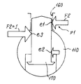
ここで使用される吸排気弁可変機構は、例えば、図9、図10に示すように、シリンダヘッドの軸受け部に両端を枢支されたロッカシャフト100を備え、ロッカシャフト100の軸部110の一部よりロッカアーム120を延出形成する。ロッカアーム120の揺動端は吸気バルブ140を開閉駆動可能に形成される。軸部110には高、低アーム(高速アームのみ示した)130がボス部131を介して枢支される。これらアーム130は高低カム(高速カムのみ示した)190により揺動可能に形成される。軸部110には半径方向に貫通孔150が形成され、そこにボス部131の係止穴160に係合可能な切換えピン170がばね180で退却付勢された状態で嵌挿される。貫通孔150には図示しない油圧制御回路からの制御油圧が供給可能である。
【0004】
このため、図示しない油圧制御回路が低圧時には切換えピン170がばね180で退却位置H1に達し、この場合、高速アーム130は空作動し、図示しない低速アーム側の挙動に応じて駆動可能である。図示しない油圧制御回路が高圧時には切換えピン170がばね180の弾性力に抗して係止穴160に係合して係止位置H2に達し、この場合、高速アーム130を介し高速カムによりロッカアーム120が揺動し、吸気バルブ140を開閉駆動することとなる。
【0005】
なお、特開平6−317128号公報には図10に示したと同様の可変動弁機構が開示される。ここでは一対の吸気バルブを同時駆動するT型ロッカアームとロッカシャフトを一体化し、ロッカシャフトの両側の軸部に高速用ロッカアームと低速用ロッカアームを枢支し、軸部に嵌着されたピストンを選択的に突出し作動させて、軸部と高速用ロッカアームを選択的に連結し、吸気バルブを高速カム、あるいは、低速カムで駆動可能とした構成が開示され、特に、各ピストン取付け位置とローラ位置を180度ずらせて取付けることで、バルブ駆動時の圧縮、引張応力のバランスを調整して、破壊強度を高めている。
【0006】
【発明が解決しようとする課題】
ところで、ロッカシャフトの軸部にロッカアームを連結する場合、例えば、図9に示すように、切換えピン170はロッカアームのボス部の係止穴160に係止される。この状態で高速アーム130が高速カム190の操作力F1を受けると、その回転力は切換えピン170より軸部110を経て、ロッカアーム120に伝わり、その揺動端の揺動により吸気バルブ140が開閉駆動する。
この場合、切換えピン170とボス部の係止穴160との当接部位p1には大きな回転操作力が作用し、十分な強度を要求される。
【0007】
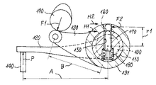
ここで、ロッカアーム120のレバー長A、高速アーム130のレバー長B、切換えピン170とボス部の係止穴160との当接部位のレバー長をr1とし、高速アーム130の操作力F1、バルブ反力P、切換えピン170とボス部の係止穴160との当接部位の係止穴反力をF2とする。
この際、図9に示すように、切換えピン170はバルブ反力Pに応じた係止穴反力F2(係止穴160との当接部位e1)と、軸受け反力f(軸受け中心位置e2)と、それらに対する反力F2+f(軸部110との当接部e3)とを受けた状態で揺動する。このため、これらe1,e2,e3の各当接部に加わる力により切換えピン170と相手接触部が弾性変形し、これにより高速カム190の揺動と、高速アーム130に切換えピン170を介して連結されるロッカアーム120の揺動とにずれが生じてしまう。すなわち、吸気バルブ140の開閉タイミングやリフト量が高速カム190のプロフィールからずれてしまうこととなり、設計どおりのエンジン性能を引き出すことができない。
【0008】
しかも、係止穴160での反力F2(=P×A/r1)は、ロッカアーム120のレバー長Aやバルブ反力Pが一定とした場合、係止穴160当接部位のレバー長r1が小さいほど大きくなり、切換えピン170とその相手接触部の弾性変形量をさらに増大させてしまう。
さらには、係止穴160当接部位のレバー長r1が小さいほど、すなわちロッカアーム120のレバー長Aと係合穴160当接部位のレバー長r1とのてこ比(A/r1)が大きいほど、切換えピン170の相手接触部の弾性変形によるロッカアーム120揺動端のずれ量が大きくなり、さらに大きなエンジン性能の低下を招いてしまうおそれがある。
【0009】
本発明の目的は、動弁機構で用いる切換えピンとその相手接触部の弾性変形を小さくして、設計カムどおりにバルブが開閉駆動でき、エンジン出力低下を防止できるエンジンの動弁装置を提供することにある。
【0010】
【課題を解決するための手段】
上述の目的を達成するため、請求項1の発明は、第1カムと第2カムを有しエンジンのシリンダヘッド上に枢支されたカムシャフトと、前記エンジンの燃焼室を開閉するバルブと、前記シリンダヘッド上に両端部が枢支され、同両端部の間の軸部より前記バルブを駆動するアームを延出させたロッカシャフトと、前記軸部にボス部が外嵌すると共に上記第1カムと第2カムの少なくとも一方のカムのプロフィールに従って前記軸部の軸部中心線を中心に揺動可能なロッカと、前記軸部に突出し可能に嵌着され前記ボス部に形成された係止穴に嵌合することで軸部とボス部を一体的に前記ロッカシャフトの両端部の端部中心線を中心に揺動可能とする切換えピンとを具備し、前記ロッカシャフトの両端部の揺動中心線に対して前記軸部の揺動中心線が切換えピンの突出し方向側に所定量ずれていることを特徴とする。
このように、ロッカシャフトの両端部の揺動中心線と軸部の揺動中心線が一致する場合と比較して、ロッカシャフトの両端部の端部中心線に対して前記軸部の軸部中心線が切換えピンの突出し方向側に所定量ずれていることで、切換えピンとボス部の穴の内壁との当接点と端部中心線との間隔が比較的大きくなり、バルブ駆動反力が加わる際の切換えピンとボス部の係止穴の内壁との当接点での反力が比較的小さくなり、切換えピンとその相手接触部の弾性変形が抑制されることにより吸気バルブの開閉タイミングやリフト量のずれが抑制され、特に、高回転域でも設計カムどおりにバルブが開閉駆動でき、エンジン出力低下を防止できる。
【0011】
請求項2の発明は、請求項1記載のエンジンの動弁装置において、前記ロッカは、前記第1カムのプロフィールに従って前記軸部中心線を中心に揺動可能な第1ロッカと、前記第2カムのプロフィールに従って前記軸部中心線を中心に揺動可能な第2ロッカとを備え、前記ボス部は、前記第1、第2ロッカに形成され前記ロッカシャフトの軸部にそれぞれ外嵌する第1、第2ボス部とを備え、前記軸部に突出し可能に嵌着され前記第1、第2ボス部に形成された第1、第2係止穴に嵌合することで軸部と前記第1、第2ボス部を選択的に一体化して揺動可能とする第1、第2切換えピンとを具備したことを特徴とする。
このように、前記ロッカシャフトの軸部が第1、第2ボス部を外嵌し、その第1、第2係止穴に軸部の第1、第2切換えピンが選択的に嵌合することができ、切換えピンとその接触部の弾性変形を抑制した上で、選択的に第1、第2カムのプロフィールに従ってバルブを駆動するので、運転域等に応じてバルブ開閉パターンを最適なパターンに切換えでき、エンジン出力向上を図れる。
【0012】
【発明の実施の形態】
図1には本発明のエンジンの動弁装置1を示し、図7にはそのエンジンの動弁装置を装備した直列4気筒、DOHC式のエンジン2を示した。
このエンジン2のシリンダヘッド3には各気筒に連通可能な図示しない吸気路及び排気路がそれぞれ形成され、各流路は一対の吸気弁4(図4参照)及び図示しない一対の排気弁によって開閉され、各吸排気弁は可変動弁機構によって駆動される。図7に示すように、シリンダヘッド3には、吸排カムシャフト5、6と、単一の排気ロッカシャフト7と、各気筒毎に分離して設けられた4つの吸気ロッカシャフト8−1から8−4とを装着する。
【0013】
吸排カムシャフト5、6は一端にタイミングギア9、10を一体的に取り付けられ、この両タイミングギアはタイミングベルト11を介して図示しないクランクシャフト側に連結され、これによりエンジン回転の1/2の回転数で両カムシャフト5、6を回転するように構成されている。
吸排カムシャフト5、6は共に一対の高低速カム12、13を各気筒対向部に配備するように形成される。
【0014】
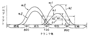
吸気カムシャフト5の第1気筒との対向部に配備される低速カム13と高速カム12は各プロフィルが異なるように形成される。図8に示すように、低速カム13のプロフィルnはリフトh1、開弁期間t1が比較的小さく、高速カム12のプロフィルmはリフトh2、開弁期間t2が比較的大きくなるように設定され、これにより、高回転高負荷側運転域での流動抵抗を抑え、充填効率を上げて出力向上を図り、低回転低負荷側運転域での気流の流動性を高めて燃焼性を改善するようにしている。なお、図示しない排気側の低速カム13と高速カム12の各プロフィルも同様の特性を確保できるように低速カム13と高速カム12の各プロフィル2、m2が設定されている。その他の気筒に対向する各カムも同様に形成される。
【0015】
第1、第4気筒の吸気弁4及び図示しない排気弁は同様の可変動弁機構M1で開閉され、第2、第3気筒の吸気弁4及び図示しない排気弁は同様の可変動弁機構M2で開閉される。
第1気筒の可変動弁機構M1の要部は、図1乃至図4に示すように、高、低ロッカ14、15のボス部21、22とこれが外嵌するロッカシャフト8−1の軸部20との間にその要部が装備される。
【0016】
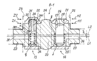
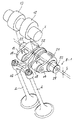
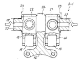
ここで、図1〜図3に示すように、吸気ロッカシャフト8−1はその両端部が小径軸支部23を形成され、その間に比較的大径の軸部20を形成され、軸部20の中央に支点端部24を膨出状に一体形成され、その支点端部24より半径方向に延出するT型アーム部16を一体形成している。T型アーム部16はその揺動端が二又状に形成され、ここが一対の吸気弁4を押圧可能に形成される。
吸気ロッカシャフト8−1は、図3に示すように、軸部20の左右に低、高速ロッカ15、14の各ボス部22、21を枢支する。
【0017】
ここで軸部20の右側には高速ロッカ14のボス部21が外嵌され、その軸部20には半径方向に貫通孔27が形成され、同孔は軸部20の端部中心線L1に沿って形成された高速油路36に連通する。なお、この高速油路36はシリンダヘッド3側の後述の高速側配給路30に連通する。貫通孔27には摺動可能に切換えピン26が嵌着される。切換えピン26はその一端に係止部gを形成され、貫通孔27は段部jを形成され、係止部gと段部j間に圧縮ばね28を配備する。なお、ボス部21には切換えピン26を嵌挿可能な係止孔29が形成される。このため貫通孔27に高圧油が供給されていないと、圧縮ばね28の弾性力で切換えピン26が退却位置H1に保持され、貫通孔27に高圧油が供給されると、圧縮ばね28の弾性力に抗して切換えピン26が突出し作動し、ボス部21の係止孔29に嵌挿され、係止位置H2に達し、軸部20と高速ロッカ14を一体化できる。
【0018】
一方、軸部20の左側には低速ロッカ15のボス部22が外嵌され、その軸部20には半径方向に貫通孔31が形成され、同孔は軸部20の端部中心線L1に沿って形成された低速油路32に連通する。なお、この低速油路32はシリンダヘッド3側の後述の低速側配給路33に連通する。貫通孔31には摺動可能に切換えピン34が嵌着される。切換えピン34はその一端にばね受け座kを形成され、ばね受けkに一端が当接する圧縮ばね34の他端がばね受けqを介してボス部22の内周壁に摺動可能に当接する。なお、ボス部22には切換えピン34を嵌挿可能な係止孔35が形成される。この係止孔35には切換えピン34内の油路341を通して低速油路32及び連通路321が連通している。
【0019】
このため低速油路32、油路341、係止孔35に油圧が供給されていないと切換えピン34は圧縮ばね34の弾性力で係止孔35に嵌挿され、係止位置Z2に保持され軸部20と低速ロッカ15を一体化できる。係止孔35に高圧油が供給されると、圧縮ばね34の弾性力に抗して切換えピン34が退却位置Z1に作動し、軸部20と低速ロッカ15を分離する。
【0020】
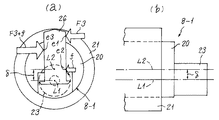
ところで、吸気ロッカシャフト8−1の小径軸支部23はシリンダヘッドの低壁より上方に突出し形成された図示しないカムジャーナルのロッカシャフト枢支部25(図3参照)に枢支される。この小径軸支部23の端部中心線L1に対して軸部20の軸部中心線L2は後述の切換えピン26の突出し方向である、図3で上方に対し、ずれ量δだけずれている。
図1乃至図3に示すように、小径軸支部23の端部中心線L1に対し、吸気ロッカシャフト8−1の軸部20及び低、高速ロッカ15、14の各ボス部22、21は揺動可能な状態にある。
なお、このような第1気筒の可変動弁機構M1と同様に第4気筒の可変動弁機構M1も構成される。
【0021】
更に、第2気筒の可変動弁機構M2と第3気筒の可変動弁機構M2は同様に構成され、ここでは第2気筒の可変動弁機構M2を説明する。
第2気筒の可変動弁機構M2の要部は、第1気筒の可変動弁機構M1の要部と同一部材を多く含み、重複部材には同一符号を付し、重複説明を略す。
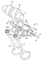
図6に示すように、第2気筒の可変動弁機構M2は高ロッカ14のボス部21とこれが外嵌する吸気ロッカシャフト8−2の軸部20との間にその要部が装備される。
【0022】
吸気ロッカシャフト8−2はその両端部が小径軸支部23を形成され、その間に比較的大径の軸部20を形成され、軸部20の中央に支点端部24を膨出状に一体形成され、その支点端部24より半径方向に延出するT型アーム部16aを一体形成している。T型アーム部16aはその揺動端が二又状に形成され、ここが第2気筒の一対の吸気弁4を押圧可能に形成される。
吸気ロッカシャフト8−2は軸部20の右に高速ロッカ14のボス部21を外嵌され、図1、図3で説明したと同様に軸部20には切換えピン26を嵌挿する貫通孔27が形成され、同孔はシリンダヘッド3側の高速側配給路30aに連通し、同様に切換えピン26が退却位置H1と係止位置H2に切り換わり、軸部20と高速ロッカ14を一体化できる。
【0023】
一方、T型アーム部16aはその揺動端近傍にローラ19aを枢支する。ローラ19aは低速カム13に当接する。
このためT型アーム部16aは、吸気ロッカシャフト8−2の軸部20に高速ロッカ14のボス部21が切換えピン26で結合されない限り、常時、低速カム13により駆動可能であり、高速ロッカ14のボス部21が切換えピン26で軸部20側のT型アーム部16aに結合されると、高速カム12でT型アーム部16aが駆動される。
【0024】
このような第2気筒の可変動弁機構M2の要部を備えた第2気筒の吸気ロッカシャフト8−2も、第1気筒の吸気ロッカシャフト8−1と同様に小径軸支部23の端部中心線L1に対して軸部20の軸部中心線L2が切換えピン26の突出し方向である、図6で上方に対し、ずれ量δだけずれている。
なお、このような第2気筒の可変動弁機構M2と同様に第3気筒の可変動弁機構M2も構成される。
【0025】
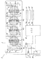
第1、4気筒の吸気ロッカシャフト8−1同じく第2、3気筒の吸気ロッカシャフト8−2の各高速油路36はシリンダヘッド3側の高速側配給路30、第1電磁弁37を介し油圧ポンプ38に連結される。更に、第1、4気筒の吸気ロッカシャフト8−1の低速油路32はシリンダヘッド3側の低速側配給路33、第2電磁弁39を介し油圧ポンプ38に連結される。
第1、第2電磁弁38、39は3方弁であり、オン時に各高速油路36、低速油路32に圧油を供給し、オフ時に各高速油路36、低速油路32側をドレーン側に接続する。なお、第1、第2電磁弁38、39はエンジンコントロールユニット(ECU)40に接続される。
【0026】
エンジンコントロールユニット40は、エンジン回転数Neをエンジン回転数センサ41より、スロットル開度θsをスロットル開度センサ42より、水温wtを水温センサ43よりそれぞれ取込み、駆動信号を第1、第2電磁弁38、39に出力するように機能する。
エンジンコントロールユニット40は、低速カム13によって駆動する低速モードか高速カム12によって駆動する高速モードかを検出し、設定された作動モードに現作動モードを切換え制御すると共に、図示しない燃料系を設定された作動モードに応じた燃料系制御を行うこととなる。
【0027】
エンジン運転域が低速モードと判断されると、第2電磁弁39をオンして低速側配給路33に高圧油を供給し、第1、第4気筒の低速ロッカ15を駆動させ、第1電磁弁38をオフとして、第1乃至第4気筒の高速ロッカ14を空作動させる。この際、暖気後にある場合には第1、第4気筒にのみ燃料供給し、第2、第3気筒を休筒させる。
【0028】
エンジン運転域が高速モードと判断されると第2電磁弁39をオフして第1、第4気筒の低速ロッカ15を空作動させ、第1電磁弁38をオンして高速側配給路30、30aに高圧油を供給し、第1乃至第4気筒の高速ロッカ14を駆動させる。これにより第1乃至第4気筒を高出力運転できる。
このようなエンジン運転中において、第1乃至第4気筒の各ロッカシャフト8−1〜8−4において、それらの軸部20に対し低、高速ロッカ15、14の各ボス部22、21が枢支し、適時に各切換えピン26、34が各ボス部22、21側の係止孔29、35に係合離脱する。
【0029】
この場合において、例えば、吸気ロッカシャフト8−1側はその小径軸支部23がロッカシャフト枢支部25(図3参照)に枢支された状態で揺動する。この際、ここでは小径軸支部23の端部中心線L1に対して軸部20の軸部中心線L2が切換えピン26の突出し方向にずれ量δだけずれている。
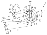
このため、図1に示すように、T型アーム部16のレバー長A、高速ロッカ14のレバー長B、切換えピン26とボス部の係止穴29との当接部位の係止孔レバー長をr2とした場合、係止孔レバー長をr2が比較的大きくなっている。即ち、従来例の図10に示した場合と比較して、ずれ量δだけ係止孔レバー長r2が大きくなる。この結果、図1に示すように、T型アーム部16のレバー長Aやバルブ反力Pが一定とした場合、係止穴29当接部位のレバー長r2が比較的大きくなり、係止穴29での係止穴反力F3(=P×A/r2)は小さくなる。
【0030】
更に、図2に示すように、切換えピン26はバルブ反力Pに応じた係止穴反力F3(係止穴29との当接部位e1)と、軸受け反力f(軸受け中心位置e2)と、それらに対する反力F3+f(軸部20との当接部e3)とを受けた状態で揺動するが、ここでは、係止孔レバー長をr2が比較的大きくなっていることより、係止穴反力F3が比較的小さくなり、e1,e2,e3の各当接部に加わる力による切換えピン26とその相手接触部の弾性変形が抑制され、これにより吸気バルブの開閉タイミングやリフト量のずれを抑制することができる。
【0031】
このように、ここでのエンジンの動弁装置では、切換えピン26が受ける係止穴反力F3が比較的小さくなることで切換えピン26とその相手接触部の変形を抑え、高回転域でも設計カムどおりにバルブ4が開閉駆動でき、エンジン出力低下を防止できる。
このような切換えピン26が受ける係止穴反力F3の低減作用は、吸気ロッカシャフト8−1の低速ピン34でも同様に作用し、その他の吸気ロッカシャフト8−2〜8−4の各ピンでも同様に作用し、それぞれ同様の効果が得られ、エンジン出力向上を図ることができる。
【0032】
【発明の効果】
以上のように、本発明は、ロッカシャフトの両端部の揺動中心線と軸部の揺動中心線が一致する場合と比較して、ロッカシャフトの両端部の端部中心線に対して前記軸部の軸部中心線が切換えピンの突出し方向側に所定量ずれていることで、切換えピンとボス部の穴の内壁との当接点と端部中心線との間隔が比較的大きくなり、バルブ駆動反力が加わる際の切換えピンとボス部の係止穴の内壁との当接点での反力が比較的小さくなり、切換えピンとその相手接触部の変形、すなわち、バルブの開閉タイミングやリフト量のカムプロフィールからのずれが抑制され、特に、高回転域でも設計カムどおりにバルブが開閉駆動でき、エンジン出力低下を防止できる。
【0033】
更に、ロッカシャフトの軸部が第1、第2ボス部を外嵌し、その第1、第2係止穴に軸部の第1、第2切換えピンが選択的に嵌合するとした場合にも、切換えピンの切換え作動時の摩擦抵抗を低減して切換え作動をスムーズにした上で、選択的に第1、第2カムのプロフィールに従ってバルブを駆動するので、運転域等に応じてバルブ開閉パターンを最適なパターンに切換えでき、エンジン出力向上を図れる。
【図面の簡単な説明】
【図1】本発明の一実施形態としてのエンジンの動弁装置の機能説明図である。
【図2】図1のエンジンの動弁装置の機能説明図で、(a)は切換えピンの摺動抵抗説明図、(b)は軸部のずれ量説明図である。
【図3】図1のエンジンの動弁装置の第1気筒でのロッカシャフトの断面図である。
【図4】図1の第1気筒での可変動弁装置の要部斜視図である。
【図5】図1の可変動弁装置の要部平面切欠断面図である。
【図6】図1の第2気筒での可変動弁装置の要部斜視図である。
【図7】図1の可変動弁装置の適用されたエンジンの要部概略構成図である。
【図8】図1の可変動弁装置のカムプロフィルを説明する図である。
【図9】従来のエンジンの動弁装置で用いる切換えピンの摺動抵抗説明図である。
【図10】従来のエンジンの動弁装置の機能説明図である。
【符号の説明】
4 吸気バルブ
5 吸気カムシャフト
8−1〜8−4 吸気ロッカシャフト
12 高速カム(第1カム)
13 低速カム(第2カム)
14 高速ロッカ(第1ロッカ)
15 低速ロッカ(第2ロッカ)
16 T型アーム部
20 軸部
21,22 ボス部
26,34 切換えピン
29,35 係止穴
C 燃焼室
L1 端部中心線(揺動中心線)
L2 軸部中心線(揺動中心線)
δ ずれ量[0001]
BACKGROUND OF THE INVENTION
INDUSTRIAL APPLICABILITY The present invention relates to a valve gear for an engine that opens and closes a valve of a combustion chamber via a rocker shaft according to a plurality of cam profiles, and in particular, can swing around the rocker shaft according to the cam profile with respect to the shaft portion of the rocker shaft The present invention relates to an engine valve operating apparatus that externally fits a rocker and engages and disengages the rocker and a shaft portion via a switching pin.
[0002]
[Prior art]
The opening / closing pattern of the intake / exhaust valve in the combustion chamber of the engine varies depending on the profile of the intake / exhaust cam that drives the intake / exhaust valves through the rocker arm.
Therefore, by selectively switching and driving at least one of the intake / exhaust valves with a low speed cam or a high speed cam, the intake / exhaust valve is driven at an opening / closing timing suitable for a change in the operation range, or the engine output is improved, or 2. Description of the Related Art There is known a variable valve mechanism for an engine that can stop the intake air supply to some cylinders in a timely manner and perform a cylinder resting operation for reducing output and reducing fuel consumption.
[0003]
The variable intake / exhaust valve mechanism used here includes, for example, a
[0004]
Therefore, when the hydraulic control circuit (not shown) is at a low pressure, the switching
[0005]
JP-A-6-317128 discloses a variable valve mechanism similar to that shown in FIG. Here, a T-type rocker arm that simultaneously drives a pair of intake valves and a rocker shaft are integrated, a high-speed rocker arm and a low-speed rocker arm are pivotally supported on both sides of the rocker shaft, and a piston fitted to the shaft is selected. In which the shaft portion and the high-speed rocker arm are selectively connected, and the intake valve can be driven by a high-speed cam or a low-speed cam. By mounting with a 180-degree offset, the balance between compression and tensile stress when the valve is driven is adjusted to increase the breaking strength.
[0006]
[Problems to be solved by the invention]
By the way, when connecting the rocker arm to the shaft portion of the rocker shaft, for example, as shown in FIG. 9, the switching
In this case, a large rotational operation force acts on the contact portion p1 between the switching
[0007]
Here, the lever length A of the rocker arm 120, the lever length B of the high-
At this time, as shown in FIG. 9, the
[0008]
Moreover, the reaction force F2 (= P × A / r1) at the
Furthermore, the smaller the lever length r1 of the
[0009]
SUMMARY OF THE INVENTION An object of the present invention is to provide an engine valve operating apparatus that can reduce the elastic deformation of a switching pin used in a valve operating mechanism and its mating contact portion so that the valve can be opened / closed according to a design cam and the engine output can be prevented from decreasing. It is in.
[0010]
[Means for Solving the Problems]
In order to achieve the above object, the invention of claim 1 includes a camshaft having a first cam and a second cam and pivotally supported on a cylinder head of an engine, a valve for opening and closing a combustion chamber of the engine, Both ends are pivotally supported on the cylinder head, a rocker shaft that extends an arm for driving the valve from a shaft between the both ends , and a boss is externally fitted to the shaft and the first A rocker that can swing around the shaft center line of the shaft portion according to the profile of at least one of the cam and the second cam, and a latch that is fitted to the shaft portion so as to protrude and is formed on the boss portion A switching pin that allows the shaft portion and the boss portion to swing integrally about the end center line of both end portions of the rocker shaft by fitting into the hole, and swinging the both end portions of the rocker shaft While the shaft is swinging with respect to the center line Line, characterized in that it shifted by a predetermined amount in the projecting direction of the switchover pin.
Thus, compared to the case where the rocking center line of both ends of the rocker shaft and the rocking center line of the shaft part coincide with each other, the shaft part of the shaft part with respect to the end center line of both ends of the rocker shaft Since the center line is displaced by a predetermined amount in the protruding direction side of the switching pin, the distance between the contact point between the switching pin and the inner wall of the hole of the boss portion and the end center line becomes relatively large, and a valve driving reaction force is applied. The reaction force at the contact point between the switching pin and the inner wall of the locking hole of the boss portion becomes relatively small, and the elastic deformation of the switching pin and its mating contact portion is suppressed, so that the opening / closing timing and lift amount of the intake valve are controlled. Deviation is suppressed, and in particular, the valve can be driven to open and close according to the design cam even in the high rotation range, and the engine output can be prevented from decreasing.
[0011]
According to a second aspect of the present invention, in the valve gear for an engine according to the first aspect, the rocker includes a first rocker that can swing around a shaft center line according to a profile of the first cam, and the second rocker. A second rocker swingable about the shaft centerline according to a cam profile, and the boss portion is formed on the first and second rockers and is fitted on the shaft portion of the rocker shaft. 1 and a second boss portion, and is fitted to the first and second locking holes formed in the first and second boss portions so as to be protruded from the shaft portion, and the shaft portion and the second boss portion. The first and second boss portions are selectively integrated, and the first and second switching pins that can be swung are provided.
As described above, the shaft portion of the rocker shaft externally fits the first and second boss portions, and the first and second switching pins of the shaft portion are selectively fitted into the first and second locking holes. The valve can be selectively driven according to the profiles of the first and second cams while suppressing the elastic deformation of the switching pin and its contact portion, so that the valve opening / closing pattern can be optimized according to the operating range. It can be switched and engine output can be improved.
[0012]
DETAILED DESCRIPTION OF THE INVENTION
FIG. 1 shows a valve operating apparatus 1 for an engine according to the present invention, and FIG. 7 shows an inline 4-
The
[0013]
The intake and
The intake /
[0014]
The low-speed cam 13 and the high-
[0015]
The
As shown in FIGS. 1 to 4, the main part of the variable valve mechanism M1 for the first cylinder includes the
[0016]
Here, as shown in FIGS. 1 to 3, the intake rocker shaft 8-1 is formed with a small-diameter
As shown in FIG. 3, the intake rocker shaft 8-1 pivotally supports the
[0017]
Here, the
[0018]
On the other hand, the
[0019]
For this reason, if hydraulic pressure is not supplied to the low-
[0020]
By the way, the small-diameter
As shown in FIGS. 1 to 3, the
The fourth cylinder variable valve mechanism M1 is configured in the same manner as the first cylinder variable valve mechanism M1.
[0021]
Further, the variable valve mechanism M2 for the second cylinder and the variable valve mechanism M2 for the third cylinder are configured in the same manner. Here, the variable valve mechanism M2 for the second cylinder will be described.
The main part of the variable valve mechanism M2 of the second cylinder includes many of the same members as the main parts of the variable valve mechanism M1 of the first cylinder.
As shown in FIG. 6, the variable valve mechanism M2 for the second cylinder is equipped with a main portion between the
[0022]
Both ends of the intake rocker shaft 8-2 are formed with a small-diameter
The intake rocker shaft 8-2 has the
[0023]
On the other hand, the T-shaped arm portion 16a pivotally supports a roller 19a in the vicinity of its swing end. The roller 19 a contacts the low speed cam 13.
Therefore, the T-shaped arm portion 16a can always be driven by the low-speed cam 13 unless the
[0024]
The intake cylinder shaft 8-2 of the second cylinder provided with the main part of the variable valve mechanism M2 of the second cylinder is also the end of the small-diameter
The third cylinder variable valve mechanism M2 is configured in the same manner as the second cylinder variable valve mechanism M2.
[0025]
The high-
The first and
[0026]
The
The
[0027]
When it is determined that the engine operating range is in the low speed mode, the second
[0028]
When it is determined that the engine operating range is the high speed mode, the second
During such engine operation, the
[0029]
In this case, for example, the intake rocker shaft 8-1 side swings in a state where the small-diameter
Therefore, as shown in FIG. 1, the lever length A of the T-shaped
[0030]
Further, as shown in FIG. 2, the switching
[0031]
In this way, in the valve gear of the engine here, the locking hole reaction force F3 received by the switching
Such a reduction action of the locking hole reaction force F3 received by the switching
[0032]
【The invention's effect】
As described above, the present invention relates to the end center lines of both ends of the rocker shaft as compared with the case where the swing center lines of both ends of the rocker shaft coincide with the swing center lines of the shaft portion. Since the shaft center line of the shaft portion is shifted by a predetermined amount in the protruding direction side of the switching pin, the distance between the contact point between the switching pin and the inner wall of the hole of the boss portion and the end center line becomes relatively large, and the valve driving reaction force at the contact point with the inner wall of the engaging hole of the switchover pin and the boss portion when the reaction force is applied is relatively small, the switching pin and the deformation of the mating contact portions, i.e., opening and closing timing and lift of the valve The amount of deviation from the cam profile is suppressed, and in particular, the valve can be driven to open and close according to the design cam even in a high rotation range, and a reduction in engine output can be prevented.
[0033]
Further, when the shaft portion of the rocker shaft is fitted over the first and second boss portions, and the first and second switching pins of the shaft portion are selectively fitted into the first and second locking holes. However, the frictional resistance during the switching operation of the switching pin is reduced to make the switching operation smooth, and the valve is selectively driven according to the profiles of the first and second cams. The pattern can be switched to an optimal pattern, and engine output can be improved.
[Brief description of the drawings]
FIG. 1 is a functional explanatory diagram of an engine valve operating apparatus according to an embodiment of the present invention.
2A and 2B are explanatory diagrams of functions of the valve operating apparatus of the engine of FIG. 1, in which FIG. 2A is an explanatory diagram of sliding resistance of a switching pin, and FIG. 2B is an explanatory diagram of a shift amount of a shaft portion;
3 is a cross-sectional view of a rocker shaft in a first cylinder of the valve operating apparatus for the engine of FIG. 1. FIG.
4 is a perspective view of a main part of the variable valve operating apparatus in the first cylinder of FIG. 1. FIG.
5 is a plan cut-away sectional view of a main part of the variable valve operating apparatus of FIG. 1. FIG.
6 is a perspective view of a main part of the variable valve operating apparatus in the second cylinder of FIG. 1. FIG.
7 is a schematic configuration diagram of a main part of an engine to which the variable valve operating device of FIG. 1 is applied. FIG.
FIG. 8 is a diagram for explaining a cam profile of the variable valve operating apparatus of FIG. 1;
FIG. 9 is an explanatory view of a sliding resistance of a switching pin used in a conventional valve gear for an engine.
FIG. 10 is a functional explanatory diagram of a conventional valve gear for an engine.
[Explanation of symbols]
4
13 Low speed cam (second cam)
14 High-speed rocker (1st rocker)
15 Low speed rocker (second rocker)
16 T-shaped
L2 Shaft center line (oscillation center line)
δ Deviation amount
Claims (2)
前記エンジンの燃焼室を開閉するバルブと、
前記シリンダヘッド上に両端部が枢支され、同両端部の間の軸部より前記バルブを駆動するアームを延出させたロッカシャフトと、
前記軸部にボス部が外嵌すると共に上記第1カムと第2カムの少なくとも一方のカムのプロフィールに従って前記軸部の軸部中心線を中心に揺動可能なロッカと、
前記軸部に突出し可能に嵌着され前記ボス部に形成された係止穴に嵌合することで軸部とボス部を一体的に前記ロッカシャフトの両端部の端部中心線を中心に揺動可能とする切換えピンとを具備し、
前記ロッカシャフトの両端部の端部中心線に対して前記軸部の軸部中心線が切換えピンの突出し方向側に所定量ずれていることを特徴とするエンジンの動弁装置。A camshaft having a first cam and a second cam and pivotally supported on an engine cylinder head;
A valve for opening and closing the combustion chamber of the engine;
A rocker shaft in which both ends are pivotally supported on the cylinder head and an arm for driving the valve is extended from a shaft portion between the both ends .
A rocker having a boss portion fitted on the shaft portion and capable of swinging about a shaft center line of the shaft portion according to a profile of at least one of the first cam and the second cam ;
The shaft portion and the boss portion are integrally rocked around the center line of the end portions of the rocker shaft by fitting the shaft portion and the boss portion into a locking hole formed so as to protrude from the shaft portion and formed in the boss portion. A switching pin that is movable,
A valve operating apparatus for an engine, wherein a shaft center line of the shaft portion is deviated by a predetermined amount toward a protruding direction of the switching pin with respect to an end center line of both ends of the rocker shaft.
前記ロッカは、前記第1カムのプロフィールに従って前記軸部中心線を中心に揺動可能な第1ロッカと、前記第2カムのプロフィールに従って前記軸部中心線を中心に揺動可能な第2ロッカとを備え、
前記ボス部は、前記第1、第2ロッカに形成され前記ロッカシャフトの軸部にそれぞれ外嵌する第1、第2ボス部とを備え、
前記軸部に突出し可能に嵌着され前記第1、第2ボス部に形成された第1、第2係止穴に嵌合することで軸部と前記第1、第2ボス部を選択的に一体化して揺動可能とする第1、第2切換えピンとを具備したことを特徴とするエンジンの動弁装置。The valve gear for an engine according to claim 1,
The rocker includes a first rocker that can swing around the shaft centerline according to the profile of the first cam, and a second rocker that can swing around the shaft centerline according to the profile of the second cam. And
The boss portion includes first and second boss portions formed on the first and second rockers and externally fitted to shaft portions of the rocker shafts, respectively .
The shaft portion and the first and second boss portions are selectively fitted by fitting into first and second locking holes formed in the first and second boss portions so as to be protruded from the shaft portion. And a first switching pin that is swingable in an integrated manner.
Priority Applications (1)
| Application Number | Priority Date | Filing Date | Title |
|---|---|---|---|
| JP2001360832A JP3991663B2 (en) | 2001-11-27 | 2001-11-27 | Engine valve gear |
Applications Claiming Priority (1)
| Application Number | Priority Date | Filing Date | Title |
|---|---|---|---|
| JP2001360832A JP3991663B2 (en) | 2001-11-27 | 2001-11-27 | Engine valve gear |
Publications (2)
| Publication Number | Publication Date |
|---|---|
| JP2003161126A JP2003161126A (en) | 2003-06-06 |
| JP3991663B2 true JP3991663B2 (en) | 2007-10-17 |
Family
ID=19171585
Family Applications (1)
| Application Number | Title | Priority Date | Filing Date |
|---|---|---|---|
| JP2001360832A Expired - Fee Related JP3991663B2 (en) | 2001-11-27 | 2001-11-27 | Engine valve gear |
Country Status (1)
| Country | Link |
|---|---|
| JP (1) | JP3991663B2 (en) |
Families Citing this family (2)
| Publication number | Priority date | Publication date | Assignee | Title |
|---|---|---|---|---|
| DE10347329A1 (en) * | 2003-10-11 | 2005-05-04 | Ina Schaeffler Kg | Operating lever for a combustion engine valve drive has coupled inner and outer levers and can be changed for different lift actions for at least one gas exchange valve |
| DE102017114575A1 (en) * | 2017-06-29 | 2019-01-03 | Man Truck & Bus Ag | Variable valve train |
-
2001
- 2001-11-27 JP JP2001360832A patent/JP3991663B2/en not_active Expired - Fee Related
Also Published As
| Publication number | Publication date |
|---|---|
| JP2003161126A (en) | 2003-06-06 |
Similar Documents
| Publication | Publication Date | Title |
|---|---|---|
| JP3946426B2 (en) | Variable valve operating device for internal combustion engine | |
| US7565887B2 (en) | Valve actuation device of internal combustion engine | |
| JPS62203913A (en) | Tappet valve device for automobile engine | |
| JP4297189B2 (en) | Variable valve operating apparatus and valve opening adjustment method | |
| JPH10317928A (en) | Engine Valve Actuator | |
| KR100642713B1 (en) | Moving valve device for internal combustion engine | |
| JP4143842B2 (en) | Valve train with internal cylinder mechanism for internal combustion engine | |
| JP2010270701A (en) | Control device for internal combustion engine | |
| JP3991663B2 (en) | Engine valve gear | |
| JPWO2007037177A1 (en) | Variable valve gear | |
| JP3876087B2 (en) | Variable valve operating device for internal combustion engine | |
| US7162983B1 (en) | Valve actuator assembly for variable displacement of an engine valve | |
| JP4094767B2 (en) | Variable valve operating device for internal combustion engine | |
| JP4935344B2 (en) | Variable valve operating apparatus for internal combustion engine, and control apparatus for internal combustion engine provided with variable valve operating apparatus | |
| JP4474058B2 (en) | Variable valve operating device for internal combustion engine | |
| KR20060070444A (en) | Copper valve device of internal combustion engine | |
| JP6001388B2 (en) | Variable valve operating device for internal combustion engine | |
| JP4106556B2 (en) | Valve operating device for internal combustion engine | |
| JP4661647B2 (en) | Control device for variable valve mechanism | |
| JP4196193B2 (en) | Valve train with internal cylinder mechanism for internal combustion engine | |
| JP4481294B2 (en) | Variable valve opening characteristics internal combustion engine | |
| KR101438600B1 (en) | Cylinder deactivation apparatus | |
| JP4632636B2 (en) | Variable valve operating device for internal combustion engine | |
| JP2599698B2 (en) | Valve train for internal combustion engine | |
| JPS63167008A (en) | Internal combustion engine valve train |
Legal Events
| Date | Code | Title | Description |
|---|---|---|---|
| A621 | Written request for application examination |
Free format text: JAPANESE INTERMEDIATE CODE: A621 Effective date: 20040416 |
|
| A977 | Report on retrieval |
Free format text: JAPANESE INTERMEDIATE CODE: A971007 Effective date: 20070201 |
|
| A131 | Notification of reasons for refusal |
Free format text: JAPANESE INTERMEDIATE CODE: A131 Effective date: 20070206 |
|
| A521 | Written amendment |
Free format text: JAPANESE INTERMEDIATE CODE: A523 Effective date: 20070406 |
|
| TRDD | Decision of grant or rejection written | ||
| A01 | Written decision to grant a patent or to grant a registration (utility model) |
Free format text: JAPANESE INTERMEDIATE CODE: A01 Effective date: 20070703 |
|
| A61 | First payment of annual fees (during grant procedure) |
Free format text: JAPANESE INTERMEDIATE CODE: A61 Effective date: 20070716 |
|
| FPAY | Renewal fee payment (event date is renewal date of database) |
Free format text: PAYMENT UNTIL: 20100803 Year of fee payment: 3 |
|
| FPAY | Renewal fee payment (event date is renewal date of database) |
Free format text: PAYMENT UNTIL: 20110803 Year of fee payment: 4 |
|
| FPAY | Renewal fee payment (event date is renewal date of database) |
Free format text: PAYMENT UNTIL: 20120803 Year of fee payment: 5 |
|
| FPAY | Renewal fee payment (event date is renewal date of database) |
Free format text: PAYMENT UNTIL: 20130803 Year of fee payment: 6 |
|
| LAPS | Cancellation because of no payment of annual fees |