JP3989552B2 - Method for manufacturing a three-dimensional article - Google Patents
Method for manufacturing a three-dimensional article Download PDFInfo
- Publication number
- JP3989552B2 JP3989552B2 JP52866697A JP52866697A JP3989552B2 JP 3989552 B2 JP3989552 B2 JP 3989552B2 JP 52866697 A JP52866697 A JP 52866697A JP 52866697 A JP52866697 A JP 52866697A JP 3989552 B2 JP3989552 B2 JP 3989552B2
- Authority
- JP
- Japan
- Prior art keywords
- powder
- article
- particles
- selective laser
- laser sintering
- Prior art date
- Legal status (The legal status is an assumption and is not a legal conclusion. Google has not performed a legal analysis and makes no representation as to the accuracy of the status listed.)
- Expired - Fee Related
Links
Images


Classifications
-
- C—CHEMISTRY; METALLURGY
- C08—ORGANIC MACROMOLECULAR COMPOUNDS; THEIR PREPARATION OR CHEMICAL WORKING-UP; COMPOSITIONS BASED THEREON
- C08J—WORKING-UP; GENERAL PROCESSES OF COMPOUNDING; AFTER-TREATMENT NOT COVERED BY SUBCLASSES C08B, C08C, C08F, C08G or C08H
- C08J3/00—Processes of treating or compounding macromolecular substances
- C08J3/12—Powdering or granulating
- C08J3/122—Pulverisation by spraying
-
- B—PERFORMING OPERATIONS; TRANSPORTING
- B29—WORKING OF PLASTICS; WORKING OF SUBSTANCES IN A PLASTIC STATE IN GENERAL
- B29C—SHAPING OR JOINING OF PLASTICS; SHAPING OF MATERIAL IN A PLASTIC STATE, NOT OTHERWISE PROVIDED FOR; AFTER-TREATMENT OF THE SHAPED PRODUCTS, e.g. REPAIRING
- B29C64/00—Additive manufacturing, i.e. manufacturing of three-dimensional [3D] objects by additive deposition, additive agglomeration or additive layering, e.g. by 3D printing, stereolithography or selective laser sintering
- B29C64/10—Processes of additive manufacturing
- B29C64/141—Processes of additive manufacturing using only solid materials
- B29C64/153—Processes of additive manufacturing using only solid materials using layers of powder being selectively joined, e.g. by selective laser sintering or melting
-
- B—PERFORMING OPERATIONS; TRANSPORTING
- B29—WORKING OF PLASTICS; WORKING OF SUBSTANCES IN A PLASTIC STATE IN GENERAL
- B29C—SHAPING OR JOINING OF PLASTICS; SHAPING OF MATERIAL IN A PLASTIC STATE, NOT OTHERWISE PROVIDED FOR; AFTER-TREATMENT OF THE SHAPED PRODUCTS, e.g. REPAIRING
- B29C67/00—Shaping techniques not covered by groups B29C39/00 - B29C65/00, B29C70/00 or B29C73/00
-
- B—PERFORMING OPERATIONS; TRANSPORTING
- B33—ADDITIVE MANUFACTURING TECHNOLOGY
- B33Y—ADDITIVE MANUFACTURING, i.e. MANUFACTURING OF THREE-DIMENSIONAL [3D] OBJECTS BY ADDITIVE DEPOSITION, ADDITIVE AGGLOMERATION OR ADDITIVE LAYERING, e.g. BY 3D PRINTING, STEREOLITHOGRAPHY OR SELECTIVE LASER SINTERING
- B33Y10/00—Processes of additive manufacturing
-
- B—PERFORMING OPERATIONS; TRANSPORTING
- B33—ADDITIVE MANUFACTURING TECHNOLOGY
- B33Y—ADDITIVE MANUFACTURING, i.e. MANUFACTURING OF THREE-DIMENSIONAL [3D] OBJECTS BY ADDITIVE DEPOSITION, ADDITIVE AGGLOMERATION OR ADDITIVE LAYERING, e.g. BY 3D PRINTING, STEREOLITHOGRAPHY OR SELECTIVE LASER SINTERING
- B33Y40/00—Auxiliary operations or equipment, e.g. for material handling
- B33Y40/10—Pre-treatment
-
- B—PERFORMING OPERATIONS; TRANSPORTING
- B33—ADDITIVE MANUFACTURING TECHNOLOGY
- B33Y—ADDITIVE MANUFACTURING, i.e. MANUFACTURING OF THREE-DIMENSIONAL [3D] OBJECTS BY ADDITIVE DEPOSITION, ADDITIVE AGGLOMERATION OR ADDITIVE LAYERING, e.g. BY 3D PRINTING, STEREOLITHOGRAPHY OR SELECTIVE LASER SINTERING
- B33Y40/00—Auxiliary operations or equipment, e.g. for material handling
- B33Y40/20—Post-treatment, e.g. curing, coating or polishing
-
- B—PERFORMING OPERATIONS; TRANSPORTING
- B33—ADDITIVE MANUFACTURING TECHNOLOGY
- B33Y—ADDITIVE MANUFACTURING, i.e. MANUFACTURING OF THREE-DIMENSIONAL [3D] OBJECTS BY ADDITIVE DEPOSITION, ADDITIVE AGGLOMERATION OR ADDITIVE LAYERING, e.g. BY 3D PRINTING, STEREOLITHOGRAPHY OR SELECTIVE LASER SINTERING
- B33Y70/00—Materials specially adapted for additive manufacturing
-
- C—CHEMISTRY; METALLURGY
- C08—ORGANIC MACROMOLECULAR COMPOUNDS; THEIR PREPARATION OR CHEMICAL WORKING-UP; COMPOSITIONS BASED THEREON
- C08J—WORKING-UP; GENERAL PROCESSES OF COMPOUNDING; AFTER-TREATMENT NOT COVERED BY SUBCLASSES C08B, C08C, C08F, C08G or C08H
- C08J2325/00—Characterised by the use of homopolymers or copolymers of compounds having one or more unsaturated aliphatic radicals, each having only one carbon-to-carbon double bond, and at least one being terminated by an aromatic carbocyclic ring; Derivatives of such polymers
- C08J2325/02—Homopolymers or copolymers of hydrocarbons
- C08J2325/04—Homopolymers or copolymers of styrene
-
- C—CHEMISTRY; METALLURGY
- C08—ORGANIC MACROMOLECULAR COMPOUNDS; THEIR PREPARATION OR CHEMICAL WORKING-UP; COMPOSITIONS BASED THEREON
- C08J—WORKING-UP; GENERAL PROCESSES OF COMPOUNDING; AFTER-TREATMENT NOT COVERED BY SUBCLASSES C08B, C08C, C08F, C08G or C08H
- C08J2333/00—Characterised by the use of homopolymers or copolymers of compounds having one or more unsaturated aliphatic radicals, each having only one carbon-to-carbon double bond, and only one being terminated by only one carboxyl radical, or of salts, anhydrides, esters, amides, imides, or nitriles thereof; Derivatives of such polymers
- C08J2333/04—Characterised by the use of homopolymers or copolymers of compounds having one or more unsaturated aliphatic radicals, each having only one carbon-to-carbon double bond, and only one being terminated by only one carboxyl radical, or of salts, anhydrides, esters, amides, imides, or nitriles thereof; Derivatives of such polymers esters
- C08J2333/06—Characterised by the use of homopolymers or copolymers of compounds having one or more unsaturated aliphatic radicals, each having only one carbon-to-carbon double bond, and only one being terminated by only one carboxyl radical, or of salts, anhydrides, esters, amides, imides, or nitriles thereof; Derivatives of such polymers esters of esters containing only carbon, hydrogen, and oxygen, the oxygen atom being present only as part of the carboxyl radical
Landscapes
- Chemical & Material Sciences (AREA)
- Engineering & Computer Science (AREA)
- Materials Engineering (AREA)
- Manufacturing & Machinery (AREA)
- Physics & Mathematics (AREA)
- Optics & Photonics (AREA)
- Health & Medical Sciences (AREA)
- Chemical Kinetics & Catalysis (AREA)
- Medicinal Chemistry (AREA)
- Polymers & Plastics (AREA)
- Organic Chemistry (AREA)
- Mechanical Engineering (AREA)
Description
本発明は、迅速原型製作(rapid prototyping)の分野に関し、更に詳細には、立体的な物品及び金型を選択的レーザー焼結によって製造する上で使用するための材料に関する。
発明の背景
近年、部品の迅速原型製作の分野では、多くの有用な物品の設計及びパイロット製造で使用するための高強度で高密度の部品を提供する上で大幅な改善がなされてきた。「迅速原型製作」という用語は、原型物品を設計図から機械加工で形成する従来の方法とは異なり、コンピューター援用設計(CAD)データベースから物品又は物品を内部で形成する成形型を直接的に自動的に製造することに関する。その結果、設計図から従来の機械を使用して原型部品及び成形型を製造するのに要する時間が、数週間から数時間に短縮される。
迅速原型製作技術の一例は、テキサス州オースチンのDTM社から入手できるシステムによって実施される選択的レーザー焼結プロセスである。この技術によれば、一度に一つの層をなして計量分配されたレーザー融着性粉体から物品が層をなして製造される。各粉体層の部分は、CADデータベースによって示された、粉体層に形成されるべき物品の断面と対応する粉体層の位置にラスター走査法で差し向けられたレーザーエネルギを加えることによって、融着され又は焼結される。追加の粉体層を計量分配し、同様の方法で選択的に融着し、隣接した層の融着済部分を互いに融着し、立体的な物品を形成する。選択的レーザー焼結技術の詳細な説明は、テキサス大学システムの評議員会に譲渡された米国特許第4,863,538号、米国特許第5,017,753号、米国特許第5,076,869号、及び米国特許第4,944,817号、及びDTM社に譲渡された米国特許第4,247,508号に記載されている。これらの特許に触れたことにより、これらの特許に開示されている内容は本明細書中に組入れたものとする。選択的レーザー焼結により、蝋、ポリカーボネート、ナイロン、他のプラスチック、及びポリマーでコーティングした材料やセラミックス等の複合材料を含む様々な材料から、立体的物品を高解像度で且つ正確な寸法で直接的に製造できる。蝋製の部品は、周知の「蝋型」プロセスによる工具の製造で使用されている。複合粉体材料の例は、テキサス大学システムの評議員会に譲渡された米国特許第4,944,817号、米国特許第5,156,697号、及び米国特許第5,284,695号に記載されている。これらの特許に触れたことにより、これらの特許に開示されている内容は本明細書中に組入れたものとする。上述のように、大きくは迅速原型製作技術、特定的には選択的レーザー焼結技術を使用し、プラスチックを含む様々な材料から原型物品又は物品を直接的に形成できる。このような原型物品は、コンピューターモデルを視覚的にチェックし、形態評価(form fit evaluation)を行う上で有用である。物品が十分な強度を備えている場合、原型に幾らかの機能的試験を加えて評価できる。更に、迅速原型製作は、型成形される物品の正の型(positive representation)(一般的には、パターン又はマスターと呼ばれる)の形成に使用できる。この場合、成形型はパターンの周囲に形成され、射出成形、インベストメント鋳造等で使用される。この方法で様々な種類の成形型を形成できる。例えば、マスターをセラミック材料で包囲し、セラミックを十分高い温度で硬化させることによって、金属のインベストメント鋳造用のセラミック成形型シェルを形成できる。この際、マスターは分解して灰になる。更に、シリコーンをベースとしたゴム製の成形型を、限られた数のプラスチック部品を型成形するための「軟質」工具として、同様の方法で形成できる。更に、パターンの周りに金属を吹付けた後、金属にバインダーを溶浸することにより、金属製型成形ダイを形成できる。
選択的レーザー焼結によって形成した物品の表面仕上げ及び高い鮮鋭度は、原型物品についての美観の観点から重要であるが、物品を成形型製造用のパターン又はマスターとして使用しようとする場合に特に重要である。当該技術において基本的であるように、パターン又はマスターの表面上の凹凸(perturbation)は、成形型に転写され、かくして、型成形された最終製品に現れる。従って、表面が滑らかに仕上げられていること、及び設計に合わせて高中実度にくっきりと形成されていることが、迅速原型製作を使用して型成形用パターン及びマスターを製造する場合に特に重要である。
原型物品の製造及び型成形用パターン及びマスターの製造の両方の選択的レーザー焼結において、多くの場合、プラスチック粉体が使用される。例えば、ポリカーボネート、ABS、ナイロン11、及びゼネカA369等のアクリル樹脂をベースとしたコポリマー等のプラスチックを選択的レーザー焼結と関連して使用することが当該技術分野で周知である。これらの粉体は、代表的には、ペレットの粉砕により製造され、粉体は、代表的には、約50μ乃至約125μの範囲の平均粒径を有する。しかしながら、これらの従来の粉体に選択的レーザー焼結を加えることによって製造された物品の鮮鋭度及び表面仕上げは、これらの大きな粒径によって比較的限定される。更に、選択的レーザー焼結によって形成された物品の表面の滑らかさ及び規則正しさが、粉体粒子の形状で決まるということが観察された。粉砕により形成された粒子は、不規則な形状をとり易く、これは、粉砕により得られた粉体を分布の小径部分(例えば平均粒径が50μ)に合わせて処理した場合でも、これらの粒子から形成された物品の表面粗さに反映する。従来の粉体は粒径が大きいため、及び不規則な形状をしているため、物品の表面を、特に型成形用パターン及びマスターとして使用するための所望の滑らかさにサンダー仕上げする工程に多くの労力及び費用を要する。
従って、選択的レーザー焼結について、粒径が小さい粉体が望ましい。これは、このような粉体は解像度を高めて鮮鋭度を向上でき、物品の表面を滑らかにできるためである。しかしながら、粉体の大部分が、粒径が小さ過ぎる(例えば、直径が15μ以下)の粉体でできている場合には、前に選択的に焼結した層の上に新たな粉体層を計量分配することにより、ひびや深い裂け目が物品の上面に形成される。これは、極めて小径の粒子間の粒子間摩擦が高いため、平面内剪断力が高くなるためである。更に、粒径が小さ過ぎる分級区分が多い粉体は、選択的レーザー焼結プロセスの完了後に物品を周囲の粉体から取り出す「粗ブレークアウト(rough breakout)」プロセスにも悪影響を及ぼす。更に、ポリマーを粉砕して粒径が約100μ以下の粉体にするのは困難であり、費用がかかる。このような粒子は、連続的粉砕工程を行うことによってのみ得られる。
粒径分布に及ぼされる別の制限は、粉体に熱処理を加えて物品にすることに関する。上掲の米国特許第5,017,753号に記載されているように、カール(層をなして発生する応力による)及び焼結膨らみ(走査していない粉体の望ましからぬ焼結)による変形を阻止するため、選択的レーザー焼結装置のターゲット面の未融着粉体及び融着済粉体の温度を制御する。従来の選択的レーザー焼結システムでは、この制御は、ターゲット面の粉体を輻射加熱器で加熱することによって、及び粉体ベッドを通して窒素等の温度制御ガスを引き込むことによって行われる。しかしながら、こうした制御にも拘わらず、極めて粒径が小さい粉体は、粉体及び粉体内で形成される物品の温度制御による望ましからぬ焼結を特に受け易い。これは、同じ時間条件及び温度条件で、小径粒子が大径粒子よりも迅速に互いに焼結するためであるためである。
別の背景技術として、乳濁液を噴霧乾燥し、粉体を形成することが当該技術分野で周知である。従来技術におけるように、噴霧乾燥は、回転スプレーノズルによって、霧化又は他の方法で乳濁液の小さな液滴を形成する工程を含む。液滴を加熱環境中に噴霧し、乳濁液中の水分を蒸発させ、実質的に球形の固体粒子である溶質の粉体を提供する。
更に別の背景技術として、空気分級は、所望の粒径分布の材料を得るための周知のプロセスである。従来技術におけるように、空気分級は、粉体と空気の混合物にサイクロンセパレータで遠心力を加えることによって、粉体中の粒子を大きさで分離する。様々な大きさの粒子が異なる距離まで移動し、大径粒子(即ち密度が均等であると仮定すると、重い粒子)は、乱流力(turbulent force)により、分離装置の中心から大きく移動する。かくして、空気分級を使用することにより、様々な大きさの粒子を選別できる。
本発明の目的は、粉体の平均粒径を小さくすると同時に小さ過ぎる粒子の有害作用をなくす、選択的レーザー焼結粉体を提供することである。
本発明の別の目的は、このような粉体に選択的レーザー焼結を加えることによって製造された、周囲型成形材料に製造中に亀裂が入らないようにするのに十分多孔質の物品を提供することである。
本発明のこの他の目的及び利点は、添付図面を参照して以下の説明を読むことによって、当業者には明らかになるであろう。
発明の概要
本発明は、容易に乳化できる微細なポリマー粉体を調製し、粉体に選択的レーザー焼結を加えることによって実施できる。このような粉体で使用するのに適したポリマーの例には、アクリル樹脂及びスチレンのホモポリマー及びコポリマーの両方が含まれる。乳濁液を噴霧乾燥して実質的に球状の粒子を製造することによって粉体を製造する。噴霧乾燥した粒子の粒径分布は、空気分級によって調節でき、平均粒径が約20μm乃至約50μmの範囲にあり、15μm以下の直径の粒子が約5容量%以下の粉体を提供する。好ましくは、粉体のガラス転移温度は室温以上であり、好ましくは300C乃至1000Cである。これは、粗ブレークアウト及び表面仕上げを容易にするためである。
このような粉体に選択的レーザー焼結を加えることによって形成した物品の密度は、好ましくは、理論値の約55%乃至約75%であり、これは、ポリマーの熱膨張率が比較的高いのにも拘わらず、金属のインベストメント鋳造用のパターンとして、及びシリコーンをベースとしたゴム製の成形型用のマスターとして使用するのに適している。
【図面の簡単な説明】
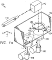
第1a図及び第1b図は、本発明の好ましい実施例に従って物品を製造するための選択的レーザー焼結システムの概略斜視図である。
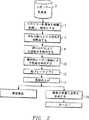
第2図は、物品又は成形型を本発明の好ましい実施例に従って製造するための方法を示すフローチャートである。
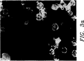
第3a図及び第3b図は、粒子が実質的に球状であることを示す、本発明の好ましい実施例に従って製造した粉体の顕微鏡写真である。
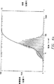
第4a図及び第4b図は、本発明の好ましい実施例による選択的レーザー焼結で有用なコポリマー粉体についての、粉体製造プロセスの異なる段階での粒径分布のプロットである。
第5図は、選択的レーザー焼結プロセスでのラスターバーの使用を例示する、第1a図及び第1b図のシステムのターゲット面の平面図である。
第6図は、選択的レーザー焼結プロセスでのベースの使用を例示する、第1a図及び第1b図のシステムの部品ベッドの断面正面図である。
好ましい実施例の詳細な説明
選択的レーザー焼結
先ず最初に、本発明の好ましい実施例を説明する目的で第1a図及び第1b図を参照し、選択的レーザー焼結システム100の構造及び作動を説明する。
第1a図に示すように、選択的レーザー焼結システム100は、チャンバ102(第1aでは、明瞭化を図る目的でチャンバ102の前扉及び頂部は示してない)を有し、このチャンバ内で選択的レーザー焼結プロセス10を実施する。ターゲット面104は、本発明を説明する目的で、部品ピストン106上に配置された熱融着性粉体の上面(焼結を予め行った場合にはこの焼結部分を含む)に関する。部品ピストン106上に配置された焼結済粉体及び未焼結粉体の容積を、ここでは、部品ベッド107と呼ぶ。ピストン106の垂直方向移動は、モータ108によって制御される。レーザー110はビームを提供し、このビームは、本明細書中上文中で言及した米国特許に記載された方法で、走査システム142によって、第1b図に示すように差し向けられる。
第1b図は、レーザー110及び走査システム142を示す。レーザー110は、レーザー自体に加え、上掲の米国特許第4,863,538号に記載された従来の制御エレメント、例えば安全シャッター、前ミラーアッセンブリ、及び発散レンズや収斂レンズ等の焦合エレメントを含む。勿論、使用されるレーザー110の種類は、多くの要因で、特に焼結されるべき粉体の種類に応じて変わる。本明細書中以下に説明する本発明のこの実施例によるポリマー粉体について、好ましくは出力を制御できるNd/YAG型レーザーを使用するのがよい。レーザー110は、好ましくは、オン−オフ変調されるように制御でき、オン状態にある場合には、レーザー110はレーザービーム105を発生し、このビームは、全体として、第1b図に矢印で示す行路に沿って移動する。
レーザービームがターゲット面104と衝突するときのレーザービームの方向を制御するため、コンピューター140及び走査システム142が更に含まれている。本発明のこの好ましい実施例では、コンピューター140は、レーザー110を制御するためのマイクロプロセッサを含み、更に、製造される物品の寸法を決定するデータを発生するためのCAD/CAMシステムを含む。本発明の好ましい実施例でコンピューター140として使用する上で、ペンティアムクラスのマイクロプロセッサを使用する浮動小数点計算が可能なパソコン等の従来のパソコンワークステーションが適している。
走査システム142は、レーザービーム105の移動行路の方向を変えるためのプリズム144を含む。レーザービーム105を適切な位置に差し向けるのに必要なプリズム144の数は、装置の物理的レイアウトに基づいて決められる。別の態様では、当該技術分野で周知のように、システム100の特定のレイアウトに応じて、レーザービーム105を差し向けるためにプリズム144の代わりに一つ又はそれ以上の固定ミラーを使用できる。走査システム142は、一対のミラー146、147を更に有する。これらのミラーは、夫々の検流計148、149によって駆動される。検流計148、149は、ミラー146、147を選択的に配向し、レーザービーム105の狙いを制御するため夫々のミラー146、147に連結されている。検流計148、149は互いに垂直に取り付けられており、そのため、ミラー146、147は、通常は、互いに対して直角に取り付けられている。走査システム142の関数発生器ドライバーが検流計148、149の移動を制御し、レーザービーム105の狙いをコンピューター140によって制御されたそのオン−オフ変調と関連してターゲット面104内に制御する。これは、ターゲット面104のところにある粉体層に形成されるべき物品の断面を決定する、コンピューター140内に記憶されたCAD/CAMデータに従って行われる。勿論、以上説明した走査システム142の代わりに別の走査システムを使用することが考えられ、このような装置は、音響−光学スキャナー、回転多角形ミラー、及び共振ミラースキャナー等を含む。
再び第1a図を参照すると、熱融着性粉体の送出は、モータ116によって制御される粉体ピストン即ち供給ピストン114及び逆回転ローラー118によって行われる。本明細書中上文中で本願に組み込んだ米国特許第5,017,753号に記載されているように、逆回転ローラー118は、チャンバ102のフロアの上方に持ち上げられた粉体をターゲット面104まで均等に且つ平らに移送する。DTM社から入手できるシンタステーション(SINTERSTATION)2000で使用されているように粉体を効率的に且つ自在に送出するため、二つの粉体ピストン114を部品ピストン106の両側に設けるのが好ましい。
形成される物品の歪みを小さくする上で、ターゲット面104の融着済粉体と未融着粉体との間の熱勾配を制御することが重要であるということが観察された。このような歪みは、次の粉体層を上に被せることによる冷却効果のため、或いはチャンバ内の低い周囲温度のため、冷却速度が速過ぎる場合にターゲット面の融着済部分の表面張力により生じる。システム100には、第1a図に示す温度センサ134、136による制御下で温度制御を行う輻射加熱器130が設けられている。この温度制御装置に加えて、或いはこの温度制御装置に代えて、上文中に組み込んだ米国特許第5,017,753号に記載されているように、ベッド107を通る加熱ダウンドラフトガス(例えば窒素等の不活性ガス)によって温度制御を行うことができる。
作動では、選択的レーザー焼結プロセス10は、システム100がプロセス12を実施し、ターゲット面104上に粉体層を計量分配することによって開始される。システム100では、粉体は、上方に移動する供給ピストン114により送出され、所定量の粉体がチャンバ102内に置かれる。ローラー118(堆積が起こらないようにするためのスクレーパが設けられており、明瞭化を図るため、このようなスクレーパは第1a図には示してない)は、供給ピストン114から、部品ピストン106上の部品ベッド107の表面上のターゲット面104に向かって及びこのターゲット面に亘って並進することにより、上文中に組み込んだ米国特許第5,017,753号に記載されているように、粉体をチャンバ102内に及びターゲット面104上に拡げる。ローラー118が粉体を供給ピストン114から提供するとき、ターゲット面104は、好ましくは、(前の層が置かれているかどうかに拘わらず)チャンバ102のフロアの僅かに(例えば0.127mm(5ミル))下にある。この厚さは、次に加工されるべき粉体層の厚さを構成する。粉体を全体に亘って滑らかに分布するため、供給ピストン114が提供する粉体の量を部品ピストン106が受け入れることのできる量以上にする。そのため、ターゲット面104に亘るローラー118の移動により僅かに余分の粉体が生じる。これは、供給ピストン114を、部品ピストン106をチャンバ102のフロアよりも下に下げる量よりも大きく(例えば、0.254mm乃至0.127mm(10ミル対5ミル))、チャンバ102のフロアの上方に持ち上げることによって行われる。更に、ローラー118の逆回転を、チャンバ102内でのローラー118の並進に対し、回転速度の並進速度に対する比が一定になるように従属させるのが好ましい。
ターゲット面104は、代表的には、物品が形成されていようといまいと、前に計量分配した粉体層である。別の態様では、以下に更に詳細に説明するように、ターゲット面104は、部品ピストン106上に置かれ且つその上に物品が形成される中実基材である。選択的レーザー焼結システム100と関連して広範な材料を使用できるが、本発明のこの実施例に従って使用される粉体はポリマー粉体である。一つの粉体層を計量分配した後、レーザービーム105を、ラスター走査の態様で、例えばx方向に走査し各走査後にy方向に漸次ステッピングすることにより、層をなして走査し、形成されるべき物品の断面と対応する粉体の部品をこの層に選択的に融着する。各粉体層の走査の完了時に次の粉体層をその上に計量分配し、プロセスを繰り返す。この次のプロセスは、多くの場合、物品を表すCADデータベースに応じて、形成される物品の形状の異なる断面に関して行われる。
粉体の形成及び物品の製造
次に第2図を参照し、粉体を形成し、形成された粉体を使用して本発明の好ましい実施例に従って物品を製造するための方法を詳細に説明する。第2図に示すように、この方法は、粉体を形成するため、ポリマー乳濁液2と関連して使用される。本発明の好ましい実施例によれば、ポリマー乳濁液2のポリマーは、アクリル樹脂又はアクリレート(例えばメチルメタクリレート、ブチルメタクリレート)、又はスチレンのホモポリマー又はコポリマーであるのがよい。これは、これらの材料が容易に乳濁液にできるためである。以下に更に詳細に説明するように、乳濁液2で使用されるポリマーの好ましい組み合わせは、好ましくは、ガラス転移温度が室温よりもはるかに高く、約300C乃至約1000Cの範囲である。ポリマー乳濁液2の好ましい例は、ゼネカ社から入手できるA639アクリル樹脂コポリマー等のアクリル樹脂をベースとしたコポリマーを固形分が約20%乃至30%になるように水で希釈した乳濁液である。
次いでポリマー乳濁液2に噴霧乾燥プロセス4を加え、粉体を形成する。当該技術分野で周知のように、乳濁液の噴霧乾燥は、粉体を形成するための従来の技術である。本発明の好ましい実施例によれば、プロセス4のポリマー乳濁液2噴霧乾燥工程は、従来の粉砕工程よりも好ましい。これは、噴霧乾燥によれば、実質的に球形の粉体粒子が得られるのに対し、ポリマーペレットの粉砕では、極めて不規則な形状の粒子が製造されるためである。第3a図及び第3bは、A639アクリル樹脂をベースとしたコポリマーを本発明の好ましい実施例に従って噴霧乾燥することによって形成した粉体の顕微鏡写真であり、これらの写真では、実質的に球形の粉体粒子が極めて明らかである。プロセス4は、好ましくは、平均粒径(容積による)が約50μ以下、好ましくは約20μ乃至約50μとなるように行われる。噴霧乾燥によって製造した粉体の平均粒径を中心とした粒径分布は、代表的には、正規分布である。
本発明のこの実施例による噴霧乾燥プロセス4により平均粒径を小さくすることによって、選択的レーザー焼結に重要な利点がもたらされる。特に、製造された物品の解像度及び鮮鋭度を大幅に向上できる。本発明に関し、シャープな縁部を有し且つ滑らかな表面を持つ表面を平均粒径が小さい粉体から更に容易に製造できる。
しかしながら、本発明に関し、選択的レーザー焼結粉体中に存在する極めて微細な粒子は、選択的レーザー焼結プロセスにとっても有害であるということがわかっている。平均粒径が約20μ以下の粉体に選択的レーザー焼結を加えた場合、選択的レーザー焼結プロセスで使用した場合に粒子間摩擦が大きくなることが観察される。この摩擦は、上文中に説明したように、システム100でローラー118を使用して粉体層を送出するときに過剰の平面剪断力が存在する場合に明らかになり、このような超微細粉体層の計量分配時に物品の上面にひびや深い裂け目が形成されるのが観察される。
更に、部品ベッド107の温度制御では、粉体は、輻射熱によって、及び部品ベッド107に通した温度が制御された窒素等のガスによって加熱される。この温度制御は、前に計量分配された融着済粉体及び未融着粉体と新たに計量分配された粉体との間の温度勾配を小さくする上で重要である。これは、このような温度勾配により物品の歪みがもたらされるためである。未融着粉体をこのように加熱することによって、粉体の融着に必要なレーザー出力が小さくなる。部品ベッド107をこのように加熱することによって、未融着粉体の望ましからぬ焼結が生じ、物品の近くの粉体をこの物品に焼結してしまう。これにより、未融着粉体からの物品の取り出しが更に困難になる。焼結が、時間、温度、及び粒径の関数であるため、極めて小さな粒径を持つ粉体は、このような望ましからぬ焼結を被り易い。本発明の好ましい実施例によれば、噴霧乾燥プロセス4で粉体を製造した後、空気分級プロセス6を実施し、極めて微細な粒子の大部分をポリマー粉体から除去する。空気分級は、粉体粒子を粒径に従って分離するのに使用される従来のプロセスである。本発明のこの好ましい実施例によれば、空気分級プロセス6は、プロセス4からのポリマー粉体を空気と混合し、混合物をヴォルテック(VORTEC)遠心式空気分級器等の従来の空気分級装置に強制的に入れることによって実施される。当該技術分野で周知のように、混合物中の大径粒子を空気分級器の外側に向かって圧送し、及びかくして懸濁状態で残る小径粒子から分離する。これは、本発明のこの実施例による粉体の密度(即ち、粒径と正比例して変化する粒子質量)が均等であるためである。空気分級器の速度(即ちrpm)は、当該技術分野で周知のように分離閾値粒径を選択するように調節される。本発明の好ましい実施例によれば、空気分級プロセス6は、直径が約15μ以下の粒径を持つ粒子を除去するように実施される。
様々な粒径の粉体粒子を分離するための、篩分けを含む他の技術が周知であるということに着目されたい。しかしながら、プロセス6の分離を実施するために篩分けを使用することは、本発明のこの実施例によれば好ましくない。これは、微細な粉体が凝集して大径粒子アッセンブリになり易いためである。噴霧乾燥プロセス4で製造した粉体中に存在するこのような凝集物は、本発明のこの好ましい実施例による空気分級プロセス6によって破壊される。
第4a図及び第4b図は、本発明の好ましい実施例による空気分級プロセス6の効果を例示するための、例示の粉体の容量分布の密度プロット及び累積密度プロットである。第4a図は、噴霧乾燥プロセス4後のA639コポリマーの粉体の計測された粒径分布(容量%)を示す。この例について第4a図に示してあるように、粒径分布は、小粒径に向かって僅かに変形したほぼ正規分布である。この例の粒径の中央値は約28μであり、平均値は約28.5μである。本発明のこの好ましい実施例に関して重要なことは、粉体の、20μ以下の直径を持つ粒子からなる分級区分の容積である。これは、第4a図の例の場合では、約28.6%であり、粉体の容積の約18%は、直径が15μ以下の粒子でできている。
次に第4b図を参照すると、この図には、空気分級プロセス6を加えた後の粒径分布が示してある。第4b図から明らかなように、直径が20μ又はそれ以下の粒子の分級区分が大幅に減少される。この例では、粉体の約10%が20μ以下の直径を持つ粒子でできており、15μ以下の直径を持つ粒子でできた粉体は約4%に過ぎない。この例示の粉体のこの例の空気分級プロセス6後の粒径の中央値は、約34μまで大きくなり(これは小径粒子が除去されたことによる)、粒径の平均値(容量%)は約33.9μまで大きくなる。このように、空気分級プロセス6は、粒径が非常に小さな粒子の数を大幅に減少するのに役立ち、かくして、粒子間摩擦及びこれにより生じる有害作用を小さくする。
再度第2図を参照する。プロセス6の後、粉体に篩分けプロセス8を加え、特定の閾値、例えば75μ以上、の粒子を除去する。上述のように、選択的レーザー焼結を受ける粉体中に存在する大径粒子は、製造される物品の表面のきめを粗くしてしまう。本発明の好ましい実施例によれば、篩分けプロセス8は空気分級プロセス6の後に実施される。プロセスのこの順番は、非常に小径の粒子が粉体から既に除去してあるために篩に粒子が凝集することが少なくなるため、好ましい。篩分けプロセス8は、ほぼ閾値限度の大きさの穴を持つメッシュに粉体を通すことによって、従来の方法で実施される。別の態様では、空気分級によって大径粒子の除去を行うことができる。この場合、廃棄されるのは大径粒子である。いずれの場合でも、篩分けプロセス8は、粉体の約75μ以上の粒子からなる分級区分の容積を所定の低いレベル、例えば約2%まで減少する。勿論、第4b図に示す粉体の場合(75μ以上の粒径の粒子が約1%)のように、大き過ぎる粒子の分布がプロセス6後に既に低い場合には、篩分けプロセス8は必要とされない。
篩分けプロセス8後の粉体は、選択的レーザー焼結プロセス10でいつでも使用できる。本発明のこの実施例の選択的レーザー焼結プロセス10は、DTM社から入手できるシンタステーション(SINTERSTATION)2000等の上文中に説明した選択的レーザー焼結システムによって実施される。上文中に説明したように、選択的レーザー焼結プロセス10は、プロセス4、6、8で製造したポリマー粉体から立体的な物品を層をなして形成する。これは、部品ベッド107のターゲット面104上に一つの粉体層を計量分配した後、前記層に形成されるべき物品の断面と一致するように選択された層の位置で粉体にレーザーエネルギを加えることによって行われる。各層の融着済粉体部分が、前の層の前に融着させた部分に融着し、その結果、粉体計量分配工程及びレーザーエネルギ施与工程を繰り返すことによって立体的物品を形成する。
本発明の好ましい実施例による選択的レーザー焼結プロセス10を実施する上で、局部的過熱が生じないように、好ましくは、レーザービーム105の各パス間に十分な時間をとる。本発明に関し、粒径を上文中に説明したように制御したポリマー粉体は、焼結膨らみ(growth)(即ち望ましからぬ焼結)が起こり易く、選択的レーザー焼結プロセスで過熱された場合に材料が劣化し易いことが観察された。このような過熱は、レーザービーム105を前に走査した粉体部分に「戻すまでの時間」が短過ぎる場合に生じる。このように、本発明の好ましい実施例によれば、選択的レーザー焼結プロセス10中のレーザービーム105による粉体の走査は、好ましくは、粉体に過熱場所が生じないように制御される。本発明の好ましい実施例によれば、所与の粉体層において、物品の非常に小さな断面が形成される(即ち、これと同時に部品ベッド107に形成される部分がない)場合、前に走査した部分でのレーザーの戻すまでの時間を長くするため、物品の走査領域の外側で、レーザーによって粉体のダミー部分を融着する。このようなダミー部分の走査(本明細書中、ラスターバーと呼ぶ)を、第5図を参照して以下に詳細に説明する。
第5図は、ターゲット面104を構成する粉体層の平面図であり、ラスターバー70がターゲット面104の一つの粉体層に存在する。この例では、物品54は、第5図のx方向に走査を行い、各x方向走査の完了時にy方向に小さな段をなしてずれるレーザービーム105(第1b図参照)のラスター走査によってターゲット面104の粉体層に形成されたものとして示してある。境界ボックス60は、この層の物品54を取り囲み、1994年10月3日に賦与された米国特許第5,352,405号に記載されている方法でレーザービーム105の走査用の境界として役立つ。この特許は、DTM社に譲渡されており、この特許に触れたことにより、その特許に開示されている内容は本明細書中に組入れたものとする。この特許に記載されているように、レーザービーム105は、境界ボックス60によって包囲された領域内だけを走査し、前記層の物品54の断面と一致する位置に向いているときにだけ付勢される。
しかしながら、本発明のこの実施例によれば、ラスターバー70が境界ボックス60の外側に配置されており、物品54のy方向に延びており、境界ボックス60のx方向外側に僅かな距離のところに配置されている。ラスターバー701、702(集合的にラスターバー70を構成する)は、各x方向走査でレーザービーム105によって融着されたターゲット面104の粉体の位置であるが、これは物品54の部分を構成しない。固化させたラスターバー70は、実際には、製造サイクルの完了時に廃棄される。しかしながら、ラスターバー70は、境界ボックス60に亘るレーザービーム105の隣接した走査間に時間間隔を強制的に挟み、及びかくして境界ボックス60に亘るレーザービーム105の戻すまでの時間を長くする。従って、物品54等の比較的小型の単一の物品について、融着を受けた粉体の過熱の問題は、ラスターバー70を設けることによって解消される。
勿論、特定断面の多数の物品を形成する場合や形成される物品が大型である場合には、レーザービーム105を1回の走査から次の走査まで戻すまでの時間は、多くの場合十分長く(例えば、数秒程度)、そのため前の走査位置で過熱が生じない。
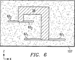
上文中に説明したように、粉体層を連続的に計量分配し、形成されるべき物品の断面と対応する各層の位置にレーザーエネルギを加えることによって、選択的レーザー焼結プロセス10による物品を層をなして製造し続ける。必要であれば、形成時の変形を最小にするため、構造を物品と組み合わせて形成するのがよい。このような構造の例は、物品56の製造時のベース62の使用を示す部品ベッド107の断面図である第6図に示してある。
ベース62は、プロセス10の選択的レーザー焼結によって形成された最終的な物品56の部品ではなく、薄い軽く焼結した部品ベッド107の粉体の位置であり、物品56の層を平らな状態で固定するのを助ける。第6図の例では、ベース621は、物品56の一部が形成される最も下の粉体層に形成され、ベース621の大きな面積は、物品の最も下の層を固定し、冷却時及び次の粉体層の計量分配時に物品が曲がらないようにするのに役立つ。同様に、ベース622は、物品56のオーバーハング部分の最も下の層に形成されており、このベースもまたこの層を曲がらないように固定する。ベース62は、その形成に使用されたレーザーエネルギが小さいことを除くと物品56と同様の方法でレーザーエネルギによって形成された薄い部分的に焼結した粉体層である。
第2図を再び参照すると、選択的レーザー焼結プロセス10の完了時に未焼結粉体によって取り囲まれた物品をシステム100から取り出し、粗ブレークアウトプロセス12を加える。粗ブレークアウトプロセス12は、未焼結粉体を物品の周囲から除去する工程を含み、この工程は、代表的には、機械的な力を手作業で加えることによってシステム100から遠隔のベンチ位置で実施される。プロセス10で形成されたベース62又はラスターバー70をこのときに同様に除去する。未焼結粉体の大部分がリサイクルされ、篩分けにより凝集粒子を除去した後、別の製造サイクルの選択的レーザー焼結プロセス10で再使用されると考えられる。
粗ブレークアウトプロセス12の後、製造した物品に表面仕上げプロセス14を加える。プロセス14で使用される代表的な表面仕上げ技術には、様々な粒度のサンドペーパーや研磨材で機械的にサンダー仕上げを施す工程が含まれる。表面仕上げプロセス14は、所望の滑らかさ及び仕上げが得られるまで実施される。
上述のように、本発明の好ましい実施例による粉体のガラス転移温度は、好ましくは、室温よりもはるかに高く、例えば300C乃至1000Cの範囲内にある。このようにガラス転移温度が高いため、非常に滑らかな仕上げが得られるまでサンダー仕上げを施したり研磨するのが他のプラスチック材料、特にガラス転移温度が室温程度の材料よりも容易な、非常に脆性のアクリル製物品が提供される。かくして、本発明の好ましい実施例によれば、物品の仕上げに要する労力がはるかに小さくなる。
表面仕上げプロセス14の後、物品を完成する。勿論、物品の用途は、そのように製造された特定の物品に応じて決まる。例えば、物品自体が原型部品又は物品である場合には、これ以上の加工工程は必要とされない。
物品が金型用のパターン即ちマスターである場合には、プロセス20を実施し物品の周りに金型を従来の方法で形成する。プロセス20で金型を形成し、物品の周囲にセラミック金型シェルを従来の方法で形成する。この方法では、ポリマー製の物品を分解するのに十分に高い温度にシェル及び物品を露呈する。物品の周囲に金属を噴霧し、次いで、噴霧した金属を溶浸して高強度の金型を形成することにより金属製金型を従来の方法で形成する。更に、プロセス20を使用し、本発明の好ましい実施例に従って粉体から形成したパターンの周囲にシリコーンを基材としたゴム製成形型を形成する。
本発明の好ましい実施例によるポリマー粉体を使用することによって、インベストメント鋳造用成形型の形成における重要な利点もまた提供される。本発明の好ましい実施例による粉体等の非晶質ポリマーには、選択的レーザー焼結プロセスで不完全溶融が加えられる。この不完全溶融は、全体として、選択的レーザー焼結プロセス10によって形成された物品を極めて多孔質にする。例えば、この粉体を選択的レーザー焼結することによって得られた物品の密度は、その理論的値(即ち、完全稠密状態の密度)の55%乃至75%程度である。多孔質の物品は、インベストメント鋳造用成形型の形成でポリマーマスターの燃焼除去(burn-out)中にシェルに亀裂が入らないようにする上で特に有用である。シェルには、物品の熱膨張率が、成形型のシェルの形成に使用されたセラミック又は他の従来の材料の熱膨張率よりも大きい場合に亀裂が入る。
ポリマーペレットの粉砕により製造した従来のポリマー粉体は、多孔質物品を提供するが、物品の表面のきめが非常に粗い。しかしながら、本発明のこの実施例によれば、制御された大きさを持つ球形粉体粒子が上述のように不完全溶融し、多孔質物品を提供するが、この物品は、表面仕上げが非常に滑らかであり、鮮鋭度が高いという特徴を備えている。これらの利点は、インベストメント鋳造用成形型の製造及びシリコーンを基材としたゴム成形型の製造で特に重要である。
選択的レーザー焼結10によって製造した物品を表面仕上げプロセス14の後に原型部品として使用しようとする場合には、物品にポリマー、エポキシ、又は他の材料を溶浸し、その構造強度を改善し、原型部品又は物品としての実用性を改善する。
例
上文中に説明したように、本発明の好ましい実施例による粉体の一例は、ゼネカ社から入手できるA639アクリル樹脂コポリマーを固形分が約20%乃至30%になるように水で希釈した乳濁液から形成した粉体である。この乳濁液を噴霧乾燥し、第4a図に示す粒径分布の球形の粉体にする。噴霧乾燥した粉体の空気分級を行い、約15μ以下の直径を持つ粒子の容量%を第4b図に示すように2%乃至5%に減少する。粉体の篩分けを行い、75μ以上の直径を持つ粒子からなる粉体の分級区分を2%以下に減少する。
DTM社から入手できるシンタステーション2000システムでこの粉体に、部品ベッド内の粉体の温度を600C乃至620Cに維持した状態で、選択的レーザー焼結を加える。焼結は、約11wに設定したレーザー出力によって、0.076mm(中心線間の距離)離間された400μのビーム幅の隣接したレーザー走査を使用して行われる。走査中のレーザービームの移動速度は、125cm/秒である。
この粉体から形成した部品の計測引張強度は、x軸及びy軸に沿って約6.9MPaであり、z軸に沿って0.7MPa乃至5.5MPaである(z軸強度は、レーザー出力、走査間隔、等の処理条件に応じて変化する)。粗ブレークアウト後、3.81μm乃至8.89μm(150μin乃至350μin)程度の算術平均表面粗さ(Ra)を持つように物品に表面仕上げを加え、従来のサンダー仕上げにより、算術平均表面粗さを0.0203μm乃至0.0381μm(0.8μin乃至1.5μin)程度に減少する。
本発明のこの例によるA639アクリル樹脂粉体の選択的焼結により製造した物品は、シリコーンを基材としたゴム製成形型を製造するためのパターンとして、及びインベストメント鋳造用成形型のシェル用のマスターとして十分に使用できる。
本発明をその好ましい実施例に従って説明したが、当業者は、本明細書及び添付図面を参照することにより、これらの実施例に対する変形及び変更を考えらつくということは勿論のことである。このような変形及び変更は、本発明の利点をもたらす。このような変形及び変更は、以下の請求の範囲の本発明の範囲内に含まれる。The present invention relates to the field of rapid prototyping and, more particularly, to materials for use in manufacturing three-dimensional articles and molds by selective laser sintering.
Background of the Invention
In recent years, in the field of rapid prototyping of parts, significant improvements have been made in providing high strength, high density parts for use in the design and pilot manufacture of many useful articles. The term “rapid prototyping” differs from the traditional method of forming a prototype article from a blueprint by machining, directly and automatically from a computer-aided design (CAD) database to form a mold that forms the article or article internally Related to manufacturing. As a result, the time required to manufacture the prototype part and the mold using the conventional machine from the design drawing is reduced from several weeks to several hours.
An example of a rapid prototyping technique is a selective laser sintering process performed by a system available from DTM, Austin, Texas. According to this technique, articles are made in layers from laser fusible powders dispensed one layer at a time. Each powder layer portion is represented by a CAD database, by applying laser energy directed by raster scanning to the position of the powder layer corresponding to the cross-section of the article to be formed on the powder layer, Fused or sintered. Additional powder layers are dispensed and selectively fused in a similar manner, and the fused portions of adjacent layers are fused together to form a three-dimensional article. A detailed description of selective laser sintering techniques can be found in U.S. Pat. No. 4,863,538, U.S. Pat. No. 5,017,753, U.S. Pat. No. 5,076, assigned to the University of Texas System Council. 869, and U.S. Pat. No. 4,944,817, and U.S. Pat. No. 4,247,508 assigned to DTM. By touching these patents, the contents disclosed in these patents are incorporated herein. Selective laser sintering enables high-resolution and accurate dimensions of three-dimensional articles directly from a variety of materials, including wax, polycarbonate, nylon, other plastics, and polymer-coated materials and composites such as ceramics Can be manufactured. Wax parts are used in the manufacture of tools by the well-known “wax mold” process. Examples of composite powder materials are found in U.S. Pat. No. 4,944,817, U.S. Pat. No. 5,156,697, and U.S. Pat. No. 5,284,695 assigned to the Council of Texas University System Council. Are listed. By touching these patents, the contents disclosed in these patents are incorporated herein. As described above, the prototype article or article can be formed directly from a variety of materials, including plastics, largely using rapid prototype fabrication techniques, particularly selective laser sintering techniques. Such a prototype article is useful for visually checking a computer model and performing form fit evaluation. If the article has sufficient strength, it can be evaluated by adding some functional tests to the prototype. Furthermore, rapid prototyping can be used to form a positive representation of the article to be molded (commonly referred to as a pattern or master). In this case, the mold is formed around the pattern and used in injection molding, investment casting, and the like. Various types of molds can be formed by this method. For example, a ceramic mold shell for metal investment casting can be formed by surrounding the master with a ceramic material and curing the ceramic at a sufficiently high temperature. At this time, the master decomposes into ash. Furthermore, a silicone-based rubber mold can be formed in a similar manner as a “soft” tool for molding a limited number of plastic parts. Furthermore, a metal mold die can be formed by spraying a metal around the pattern and then infiltrating a binder into the metal.
The surface finish and high sharpness of the article formed by selective laser sintering is important from the aesthetic point of view of the original article, but is particularly important when the article is to be used as a pattern or master for mold making. It is. As is fundamental in the art, the pattern or perturbation on the surface of the master is transferred to the mold and thus appears in the final molded product. Therefore, the smooth finish of the surface and the sharpness with high to medium solidity to suit the design is particularly important when manufacturing mold patterns and masters using rapid prototyping. It is.
Plastic powders are often used in the selective laser sintering of both the production of prototype articles and the production of mold patterns and masters. For example, it is well known in the art to use plastics such as copolymers based on acrylic resins such as polycarbonate, ABS, nylon 11, and Geneca A369 in connection with selective laser sintering. These powders are typically produced by pulverization of pellets, and the powders typically have an average particle size in the range of about 50 microns to about 125 microns. However, the sharpness and surface finish of articles made by applying selective laser sintering to these conventional powders are relatively limited by their large particle size. Furthermore, it has been observed that the smoothness and regularity of the surface of the article formed by selective laser sintering is determined by the shape of the powder particles. The particles formed by pulverization tend to take irregular shapes, even when the powder obtained by pulverization is processed according to the small diameter part of the distribution (for example, the average particle size is 50 μ). Reflected in the surface roughness of the article formed from. Because conventional powders are large in particle size and irregularly shaped, they are often used in the process of sanding the surface of an article to the desired smoothness, especially for use as a mold pattern and master. Cost and labor.
Therefore, a powder with a small particle size is desirable for selective laser sintering. This is because such a powder can improve resolution and sharpness, and can smooth the surface of the article. However, if the majority of the powder is made of powder with a particle size that is too small (for example, a diameter of 15 μm or less), a new powder layer over the previously selectively sintered layer By dispensing, cracks and deep tears are formed on the top surface of the article. This is because the in-plane shear force increases because the interparticle friction between extremely small diameter particles is high. In addition, powders with many classification categories that are too small in particle size also adversely affect a “rough breakout” process in which the article is removed from the surrounding powder after the selective laser sintering process is complete. Furthermore, it is difficult and expensive to pulverize the polymer into a powder having a particle size of about 100 μm or less. Such particles can only be obtained by performing a continuous grinding process.
Another limitation imposed on the particle size distribution relates to subjecting the powder to heat treatment into articles. Curl (due to stress generated in layers) and sintering bulge (undesired sintering of unscanned powder) as described in US Pat. No. 5,017,753, supra. In order to prevent deformation due to the above, the temperature of the unfused powder and the fused powder on the target surface of the selective laser sintering apparatus is controlled. In conventional selective laser sintering systems, this control is accomplished by heating the powder on the target surface with a radiant heater and by drawing a temperature controlled gas such as nitrogen through the powder bed. However, despite such control, powders with very small particle sizes are particularly susceptible to unwanted sintering due to temperature control of the powder and articles formed within the powder. This is because, under the same time and temperature conditions, the small diameter particles sinter together faster than the large diameter particles.
As another background art, it is well known in the art to spray dry an emulsion to form a powder. As in the prior art, spray drying involves atomizing or otherwise forming small droplets of the emulsion by means of a rotating spray nozzle. The droplets are sprayed into a heated environment to evaporate the water in the emulsion and provide a solute powder that is substantially spherical solid particles.
As yet another background art, air classification is a well-known process for obtaining a material with a desired particle size distribution. As in the prior art, air classification separates particles in powder by size by applying centrifugal force to a mixture of powder and air with a cyclone separator. Various sized particles move to different distances, and large particles (ie, heavy particles, assuming uniform density) move greatly from the center of the separator due to turbulent force. Thus, particles of various sizes can be sorted by using air classification.
It is an object of the present invention to provide a selective laser sintered powder that reduces the average particle size of the powder and at the same time eliminates the harmful effects of particles that are too small.
Another object of the present invention is to provide an article made by adding selective laser sintering to such a powder that is sufficiently porous to prevent cracking during fabrication of the surrounding mold material. Is to provide.
Other objects and advantages of the present invention will become apparent to those of ordinary skill in the art by reading the following description with reference to the accompanying drawings.
Summary of the Invention
The present invention can be practiced by preparing a fine polymer powder that can be easily emulsified and subjecting the powder to selective laser sintering. Examples of polymers suitable for use in such powders include both acrylic resins and styrene homopolymers and copolymers. Powders are produced by spray drying the emulsion to produce substantially spherical particles. The particle size distribution of the spray-dried particles can be adjusted by air classification to provide a powder having an average particle size in the range of about 20 μm to about 50 μm, and particles having a diameter of 15 μm or less of about 5% by volume or less. Preferably, the glass transition temperature of the powder is not less than room temperature, preferably from 300C to 1000C. This is to facilitate rough breakout and surface finish.
The density of articles formed by adding selective laser sintering to such powders is preferably about 55% to about 75% of theory, which is a relatively high coefficient of thermal expansion of the polymer. Nevertheless, it is suitable for use as a pattern for metal investment casting and as a master for rubber-based molds based on silicone.
[Brief description of the drawings]
FIGS. 1a and 1b are schematic perspective views of a selective laser sintering system for manufacturing an article in accordance with a preferred embodiment of the present invention.
FIG. 2 is a flow chart illustrating a method for manufacturing an article or mold according to a preferred embodiment of the present invention.
Figures 3a and 3b are photomicrographs of powders made in accordance with a preferred embodiment of the present invention showing that the particles are substantially spherical.
Figures 4a and 4b are plots of particle size distributions at different stages of the powder manufacturing process for copolymer powders useful in selective laser sintering according to a preferred embodiment of the present invention.
FIG. 5 is a plan view of the target surface of the system of FIGS. 1a and 1b illustrating the use of a raster bar in a selective laser sintering process.
FIG. 6 is a cross-sectional front view of the component bed of the system of FIGS. 1a and 1b illustrating the use of the base in a selective laser sintering process.
Detailed Description of the Preferred Embodiment
Selective laser sintering
First, the structure and operation of the selective
As shown in FIG. 1a, the selective
FIG. 1 b shows the
A
The
Referring again to FIG. 1a, the heat fusible powder is delivered by a powder piston or
It has been observed that it is important to control the thermal gradient between the fused and unfused powder on the
In operation, the selective
The
Powder formation and article manufacture
Referring now to FIG. 2, a method for forming a powder and using the formed powder to produce an article according to a preferred embodiment of the present invention will be described in detail. As shown in FIG. 2, this method is used in conjunction with
A spray drying process 4 is then added to the
Reducing the average particle size by the spray drying process 4 according to this embodiment of the invention provides significant advantages for selective laser sintering. In particular, the resolution and sharpness of manufactured articles can be greatly improved. With respect to the present invention, a surface having a sharp edge and a smooth surface can be more easily produced from a powder having a small average particle diameter.
However, with the present invention, it has been found that the very fine particles present in the selective laser sintering powder are also detrimental to the selective laser sintering process. When selective laser sintering is applied to a powder having an average particle size of about 20 microns or less, it is observed that interparticle friction increases when used in a selective laser sintering process. This friction becomes apparent when excessive plane shear forces are present when delivering a powder layer using the
Further, in the temperature control of the
Note that other techniques, including sieving, for separating powder particles of various particle sizes are well known. However, the use of sieving to carry out the separation of process 6 is not preferred according to this embodiment of the invention. This is because fine powder tends to agglomerate into a large particle assembly. Such agglomerates present in the powder produced by the spray drying process 4 are destroyed by the air classification process 6 according to this preferred embodiment of the invention.
FIGS. 4a and 4b are density plots and cumulative density plots of an exemplary powder volume distribution to illustrate the effect of the air classification process 6 according to a preferred embodiment of the present invention. FIG. 4a shows the measured particle size distribution (% by volume) of the A639 copolymer powder after spray drying process 4. As shown in FIG. 4a for this example, the particle size distribution is a substantially normal distribution that is slightly deformed towards smaller particle sizes. The median particle size in this example is about 28μ and the average value is about 28.5μ. What is important for this preferred embodiment of the invention is the volume of the classification section of the powder consisting of particles having a diameter of 20 microns or less. This is about 28.6% in the case of the example of FIG. 4a, and about 18% of the volume of the powder is made of particles having a diameter of 15 μm or less.
Reference is now made to FIG. 4b, which shows the particle size distribution after the air classification process 6 has been applied. As is apparent from FIG. 4b, the classification of particles with a diameter of 20 μ or less is greatly reduced. In this example, about 10% of the powder is made of particles having a diameter of 20 μm or less, and the powder made of particles having a diameter of 15 μm or less is only about 4%. The median particle size of this exemplary powder after this example air classification process 6 increases to about 34μ (because small particles have been removed) and the average particle size (volume%) is Increases to about 33.9μ. Thus, the air classification process 6 helps to greatly reduce the number of particles with very small particle sizes, thus reducing interparticle friction and the resulting adverse effects.
FIG. 2 will be referred to again. After process 6, a
The powder after the
In performing the selective
FIG. 5 is a plan view of the powder layer constituting the
However, according to this embodiment of the invention, the raster bar 70 is located outside the
Of course, when a large number of articles having a specific cross section are formed or the article to be formed is large, the time until the
As described above, the powder layer is continuously dispensed and the article by the selective
The base 62 is not the part of the
Referring again to FIG. 2, upon completion of the selective
After the
As mentioned above, the glass transition temperature of the powder according to a preferred embodiment of the present invention is preferably much higher than room temperature, for example in the range of 300C to 1000C. Because of this high glass transition temperature, it is extremely brittle, which is easier to sand or polish than other plastic materials, especially those with a glass transition temperature of about room temperature, until a very smooth finish is obtained. An acrylic article is provided. Thus, according to the preferred embodiment of the present invention, much less work is required to finish the article.
After the
If the article is a mold pattern or master,
The use of polymer powders according to preferred embodiments of the present invention also provides significant advantages in forming investment casting molds. An amorphous polymer such as a powder according to a preferred embodiment of the present invention is subjected to incomplete melting in a selective laser sintering process. This incomplete melting generally makes the article formed by the selective
Conventional polymer powders produced by pulverization of polymer pellets provide a porous article, but the surface of the article is very rough. However, according to this embodiment of the invention, the spherical powder particles with controlled size are incompletely melted as described above to provide a porous article, which has a very surface finish. It is smooth and has high sharpness. These advantages are particularly important in the manufacture of investment casting molds and silicone-based rubber molds.
If an article manufactured by
Example
As described above, an example of a powder according to a preferred embodiment of the present invention is an emulsion of A639 acrylic resin copolymer available from Zeneca Company diluted with water to a solid content of about 20% to 30%. It is a powder formed from a liquid. This emulsion is spray-dried to give a spherical powder having a particle size distribution shown in FIG. 4a. The air-drying of the spray-dried powder is performed and the volume percentage of particles having a diameter of about 15μ or less is reduced to 2% to 5% as shown in FIG. 4b. Powder sieving is performed, and the classification classification of the powder composed of particles having a diameter of 75 μ or more is reduced to 2% or less.
This powder is subjected to selective laser sintering while maintaining the temperature of the powder in the component bed between 600C and 620C with a Sinter Station 2000 system available from DTM. Sintering is performed using adjacent laser scans with a beam width of 400μ spaced 0.076 mm (distance between centerlines) with a laser power set at about 11 w. The moving speed of the laser beam during scanning is 125 cm / sec.
The measured tensile strength of the part formed from this powder is about 6.9 MPa along the x-axis and y-axis, and 0.7 MPa to 5.5 MPa along the z-axis (the z-axis strength is the laser output power). , Depending on processing conditions such as scanning interval). After rough breakout, surface finish is added to the article so that it has an arithmetic average surface roughness (Ra) of about 3.81 μm to 8.89 μm (150 μin to 350 μin), and the arithmetic average surface roughness is reduced by conventional sanding. It decreases to about 0.0203 μm to 0.0381 μm (0.8 μin to 1.5 μin).
Articles made by selective sintering of A639 acrylic resin powder according to this example of the invention are used as patterns for producing silicone-based rubber molds and for investment casting mold shells. Can be fully used as a master.
Although the present invention has been described in accordance with its preferred embodiments, it will be appreciated that variations and modifications to these embodiments will occur to those skilled in the art by reference to the specification and the accompanying drawings. Such variations and modifications provide the advantages of the present invention. Such variations and modifications are included within the scope of the present invention as set forth in the following claims.
Claims (9)
体積平均径が20μm乃至50μmの実質的に球状のポリマー粒子からなる、15μm以下の直径の粒子からなる粉体の容積分率が5%以下の粉体層をターゲット面に計量分配する工程と、
粉体層の選択された位置を融着する工程と、
多数の層について計量分配工程及び融着工程を繰り返し、連続した層の融着部分を直前の層の部分に融着し、物品を形成する工程とを有することを特徴とする方法。In the method of manufacturing a three-dimensional article,
The volume average diameter of from substantially spherical polymer particles of 20 [mu] m to 50.mu. m, the volume fraction of the powder consisting of particles of a diameter less than 15.mu. m to dispense more than 5% of the powder layer to the target surface Process,
Fusing selected positions of the powder layer;
Repeating the dispensing step and the fusing step for a number of layers, fusing a fused portion of successive layers to a portion of the immediately preceding layer, and forming an article.
除去工程の後、前記物品の周囲に成形型を形成する工程を有する、請求項1に記載の方法。After repeating the dispensing step and fusing step, a step of removing MiToru Chakukotai from around the article, and after the removal step comprises forming a mold around the article, according to claim 1 The method described in 1.
Applications Claiming Priority (3)
| Application Number | Priority Date | Filing Date | Title |
|---|---|---|---|
| US08/597,805 | 1996-02-07 | ||
| US08/597,805 US5817206A (en) | 1996-02-07 | 1996-02-07 | Selective laser sintering of polymer powder of controlled particle size distribution |
| PCT/US1997/001938 WO1997029148A1 (en) | 1996-02-07 | 1997-02-06 | Polymer powder of controlled particle size distribution |
Publications (2)
| Publication Number | Publication Date |
|---|---|
| JP2000504642A JP2000504642A (en) | 2000-04-18 |
| JP3989552B2 true JP3989552B2 (en) | 2007-10-10 |
Family
ID=24393000
Family Applications (1)
| Application Number | Title | Priority Date | Filing Date |
|---|---|---|---|
| JP52866697A Expired - Fee Related JP3989552B2 (en) | 1996-02-07 | 1997-02-06 | Method for manufacturing a three-dimensional article |
Country Status (7)
| Country | Link |
|---|---|
| US (1) | US5817206A (en) |
| EP (1) | EP0879261A1 (en) |
| JP (1) | JP3989552B2 (en) |
| KR (1) | KR19990082365A (en) |
| AU (1) | AU2262297A (en) |
| CA (1) | CA2244754A1 (en) |
| WO (1) | WO1997029148A1 (en) |
Families Citing this family (62)
| Publication number | Priority date | Publication date | Assignee | Title |
|---|---|---|---|---|
| DE19820725A1 (en) * | 1998-05-11 | 1999-11-18 | Bayer Ag | Three-dimensional polymeric patterns, useful for production of ceramic preforms for fine casting of metals |
| JP3518726B2 (en) | 1998-07-13 | 2004-04-12 | トヨタ自動車株式会社 | Additive manufacturing method and resin-coated sand for additive manufacturing |
| DE19848897A1 (en) | 1998-10-23 | 2000-04-27 | Agfa Gevaert Ag | Production of monodisperse spherical polymers |
| US6200514B1 (en) | 1999-02-09 | 2001-03-13 | Baker Hughes Incorporated | Process of making a bit body and mold therefor |
| DE19918981A1 (en) * | 1999-04-27 | 2000-11-02 | Bayer Ag | Process and material for the production of model bodies |
| DE19929199A1 (en) * | 1999-06-25 | 2001-01-18 | Hap Handhabungs Automatisierun | Method and device for producing a three-dimensional object |
| RU2217266C2 (en) * | 1999-12-30 | 2003-11-27 | Физический институт им. П.Н. Лебедева РАН | Method for making three-dimensional articles of bimetallic powder compositions |
| US6730998B1 (en) | 2000-02-10 | 2004-05-04 | Micron Technology, Inc. | Stereolithographic method for fabricating heat sinks, stereolithographically fabricated heat sinks, and semiconductor devices including same |
| US6276431B1 (en) | 2000-02-29 | 2001-08-21 | Visteon Global Technologies, Inc. | Method of making a spray formed rapid tool |
| US6432752B1 (en) * | 2000-08-17 | 2002-08-13 | Micron Technology, Inc. | Stereolithographic methods for fabricating hermetic semiconductor device packages and semiconductor devices including stereolithographically fabricated hermetic packages |
| TW506868B (en) * | 2000-10-05 | 2002-10-21 | Matsushita Electric Works Ltd | Method of and apparatus for making a three-dimensional object |
| EP1234625A1 (en) * | 2001-02-21 | 2002-08-28 | Trumpf Werkzeugmaschinen GmbH + Co. KG | Process and apparatus for producing a shaped body by selective laser sintering |
| US6820677B2 (en) | 2002-08-20 | 2004-11-23 | Ford Motor Company | Method of making a spray formed article |
| US6793151B2 (en) * | 2002-09-18 | 2004-09-21 | R&J Inventions, Llc | Apparatus and method for centrifugal material deposition and products thereof |
| DE10256097A1 (en) * | 2002-12-02 | 2004-06-17 | Eos Gmbh Electro Optical Systems | Plastic powder for laser sintering |
| WO2005021247A1 (en) * | 2003-08-28 | 2005-03-10 | Fuji Photo Film Co., Ltd. | Process for producing three-dimensional shaped article |
| JP2005262865A (en) * | 2004-02-17 | 2005-09-29 | Toshiki Shinno | Three-dimensional structure transparency method and transparent three-dimensional structure |
| US7261542B2 (en) | 2004-03-18 | 2007-08-28 | Desktop Factory, Inc. | Apparatus for three dimensional printing using image layers |
| TWI253379B (en) * | 2004-04-08 | 2006-04-21 | Wei-Hsiang Lai | Method and apparatus for rapid prototyping using computer-printer aided to object realization |
| US20060214335A1 (en) * | 2005-03-09 | 2006-09-28 | 3D Systems, Inc. | Laser sintering powder recycle system |
| WO2007024856A2 (en) * | 2005-08-23 | 2007-03-01 | Valspar Sourcing, Inc. | Infiltrated articles prepared by laser sintering method and method of manufacturing the same |
| JP5034216B2 (en) * | 2005-11-02 | 2012-09-26 | テクノポリマー株式会社 | Styrenic resin particles for modeling by SLS method and manufacturing method thereof |
| DE102006019963B4 (en) * | 2006-04-28 | 2023-12-07 | Envisiontec Gmbh | Device and method for producing a three-dimensional object by layer-by-layer solidifying a material that can be solidified under the influence of electromagnetic radiation using mask exposure |
| DE102006023484A1 (en) * | 2006-05-18 | 2007-11-22 | Eos Gmbh Electro Optical Systems | Apparatus and method for layering a three-dimensional object from a powdery building material |
| US8187521B2 (en) * | 2006-07-27 | 2012-05-29 | Arcam Ab | Method and device for producing three-dimensional objects |
| EP2137238B1 (en) * | 2007-03-26 | 2017-04-19 | Nippon Shokubai Co., Ltd. | Classification method of particulate water absorbent resin |
| US10226919B2 (en) * | 2007-07-18 | 2019-03-12 | Voxeljet Ag | Articles and structures prepared by three-dimensional printing method |
| WO2009071942A2 (en) * | 2007-12-04 | 2009-06-11 | Bae Systems Plc | Improvements relating to sonar baffles and backings |
| EP2157566A1 (en) * | 2008-07-04 | 2010-02-24 | BAE Systems PLC | Improvements Relating to Sonar Baffles and Backings |
| FR2939075B1 (en) * | 2008-12-01 | 2010-12-17 | Rhodia Operations | REALIZATION OF ARTICLE BY SELECTIVE FUSION OF POLYMER POWDER LAYERS |
| US8709330B2 (en) * | 2009-01-06 | 2014-04-29 | The Boeing Company | Manufacturing aircraft parts |
| CN102164735A (en) * | 2009-01-23 | 2011-08-24 | Eos有限公司电镀光纤系统 | Method and system for reusing residual powder from an installation for the rapid prototyping of three-dimensional objects |
| JP2013049137A (en) * | 2011-08-30 | 2013-03-14 | Sony Corp | Powder removing apparatus, molding system, and method of manufacturing molded object |
| JP5749862B2 (en) * | 2011-09-15 | 2015-07-15 | ストラタシス リミテッド | Controlling the density of printing material dispensed |
| CH705662A1 (en) * | 2011-11-04 | 2013-05-15 | Alstom Technology Ltd | Process for producing articles of a solidified by gamma-prime nickel-base superalloy excretion by selective laser melting (SLM). |
| FR2982519B1 (en) * | 2011-11-10 | 2020-02-21 | Arkema France | PROCESS OF CRUSHING POLYARYL ETHER CETONES |
| US10011089B2 (en) | 2011-12-31 | 2018-07-03 | The Boeing Company | Method of reinforcement for additive manufacturing |
| US9481130B2 (en) * | 2012-03-14 | 2016-11-01 | Inteva Products, Llc | Method of permanently joining plastic components and a plastic component joining assembly |
| EP2935412B1 (en) | 2012-12-19 | 2021-04-28 | Hexcel Corporation | Method for preparing fine powders for use in selective laser sintering processes |
| FR3002527A1 (en) * | 2013-02-26 | 2014-08-29 | Univ Lorraine | ELECTROLYTE SEPARATION WALL FOR SELECTIVE CATION TRANSFER THROUGH THE WALL AND PROCESS FOR PRODUCING SAID WALL |
| US9931785B2 (en) | 2013-03-15 | 2018-04-03 | 3D Systems, Inc. | Chute for laser sintering systems |
| JP6018007B2 (en) * | 2013-03-29 | 2016-11-02 | 積水化成品工業株式会社 | Acrylic resin particles, coating composition and optical material |
| US10207327B2 (en) | 2013-08-20 | 2019-02-19 | The Trustees Of Princeton University | Density enhancement methods and compositions |
| US10434545B2 (en) * | 2014-01-17 | 2019-10-08 | United Technologies Corporation | Particle separator for an additive manufacturing system and method of operation |
| JP2017516680A (en) * | 2014-04-07 | 2017-06-22 | サビック グローバル テクノロジーズ ベスローテン フェンノートシャップ | Thermoplastic polymer for powder bed melt bonding. |
| JP6552727B2 (en) | 2015-09-04 | 2019-07-31 | サビック グローバル テクノロジーズ ベスローテン フェンノートシャップ | Powder composition, method of preparing articles and coatings from powder composition, and articles prepared therefrom |
| GB201522691D0 (en) * | 2015-12-22 | 2016-02-03 | Lucite Internat Speciality Polymers And Resins Ltd | Additive manufacturing composition |
| US10610931B2 (en) | 2016-02-16 | 2020-04-07 | Board Of Regents, The University Of Texas System | Method and system for producing functionally graded structures in powder bed fusion processing |
| EP3231588A1 (en) * | 2016-04-12 | 2017-10-18 | Evonik Röhm GmbH | Spray-dried soft phase emulsion polymer for the filling of the spandrel in polymer bead layers in binder jetting method |
| US10315409B2 (en) * | 2016-07-20 | 2019-06-11 | Xerox Corporation | Method of selective laser sintering |
| US10649355B2 (en) | 2016-07-20 | 2020-05-12 | Xerox Corporation | Method of making a polymer composite |
| JP6402810B1 (en) | 2016-07-22 | 2018-10-10 | 株式会社リコー | Three-dimensional modeling resin powder, three-dimensional model manufacturing apparatus, and three-dimensional model manufacturing method |
| US10919286B2 (en) * | 2017-01-13 | 2021-02-16 | GM Global Technology Operations LLC | Powder bed fusion system with point and area scanning laser beams |
| JP6821446B2 (en) * | 2017-01-18 | 2021-01-27 | 三菱重工業株式会社 | Manufacturing method and inspection method of metal powder for laminated molding |
| CN115028971A (en) * | 2017-03-21 | 2022-09-09 | 株式会社理光 | Resin powder for making three-dimensional objects and method of making three-dimensional objects |
| JP2018158571A (en) * | 2017-03-21 | 2018-10-11 | 株式会社リコー | Three-dimensional modeling resin powder, three-dimensional model manufacturing method, and three-dimensional model manufacturing apparatus |
| US11919246B2 (en) | 2017-07-11 | 2024-03-05 | Daniel S. Clark | 5D part growing machine with volumetric display technology |
| US10967578B2 (en) | 2017-07-11 | 2021-04-06 | Daniel S. Clark | 5D part growing machine with volumetric display technology |
| BR112020012407A2 (en) * | 2017-12-21 | 2020-11-24 | Braskem America, Inc. | laser sintering device to produce parts composed of powder materials, method for producing a three-dimensional object, and, three-dimensional object |
| US11993722B2 (en) | 2019-05-24 | 2024-05-28 | Hexcel Corporation | Twice recycled polymer powder composition for additive manufacturing including PEKK, siloxane and carbon fiber |
| JP7221157B2 (en) * | 2019-07-02 | 2023-02-13 | 株式会社荏原製作所 | AM device |
| FI4210950T3 (en) * | 2020-09-08 | 2024-12-13 | Evonik Operations Gmbh | Selective laser sintering of polymeric powders embedded with water-soluble flow additives |
Family Cites Families (19)
| Publication number | Priority date | Publication date | Assignee | Title |
|---|---|---|---|---|
| DE2543542C2 (en) * | 1975-09-30 | 1986-10-02 | Röhm GmbH, 6100 Darmstadt | Process for making a plastisol |
| US4247508B1 (en) * | 1979-12-03 | 1996-10-01 | Dtm Corp | Molding process |
| KR960008015B1 (en) * | 1986-10-17 | 1996-06-19 | 보드 오브 리젼츠, 디 유니버시티 오브 텍사스 시스템 | Method and apparatus for manufacturing parts by selective sintering |
| US4944817A (en) * | 1986-10-17 | 1990-07-31 | Board Of Regents, The University Of Texas System | Multiple material systems for selective beam sintering |
| US5017753A (en) * | 1986-10-17 | 1991-05-21 | Board Of Regents, The University Of Texas System | Method and apparatus for producing parts by selective sintering |
| US4863538A (en) * | 1986-10-17 | 1989-09-05 | Board Of Regents, The University Of Texas System | Method and apparatus for producing parts by selective sintering |
| JPS63260972A (en) * | 1987-04-17 | 1988-10-27 | Sekisui Chem Co Ltd | Microspherical pressure sensitive adhesive |
| JPH02133471A (en) * | 1988-11-15 | 1990-05-22 | Ube Ind Ltd | paint composition |
| AU643700B2 (en) * | 1989-09-05 | 1993-11-25 | University Of Texas System, The | Multiple material systems and assisted powder handling for selective beam sintering |
| US5156697A (en) * | 1989-09-05 | 1992-10-20 | Board Of Regents, The University Of Texas System | Selective laser sintering of parts by compound formation of precursor powders |
| US5284695A (en) * | 1989-09-05 | 1994-02-08 | Board Of Regents, The University Of Texas System | Method of producing high-temperature parts by way of low-temperature sintering |
| US5385780A (en) * | 1990-12-05 | 1995-01-31 | The B. F. Goodrich Company | Sinterable mass of polymer powder having resistance to caking and method of preparing the mass |
| US5252264A (en) * | 1991-11-08 | 1993-10-12 | Dtm Corporation | Apparatus and method for producing parts with multi-directional powder delivery |
| JPH06106628A (en) * | 1992-09-25 | 1994-04-19 | Ricoh Co Ltd | 3D image production system |
| US5527877A (en) * | 1992-11-23 | 1996-06-18 | Dtm Corporation | Sinterable semi-crystalline powder and near-fully dense article formed therewith |
| US5304329A (en) * | 1992-11-23 | 1994-04-19 | The B. F. Goodrich Company | Method of recovering recyclable unsintered powder from the part bed of a selective laser-sintering machine |
| US5352405A (en) * | 1992-12-18 | 1994-10-04 | Dtm Corporation | Thermal control of selective laser sintering via control of the laser scan |
| US5490962A (en) * | 1993-10-18 | 1996-02-13 | Massachusetts Institute Of Technology | Preparation of medical devices by solid free-form fabrication methods |
| US5733497A (en) * | 1995-03-31 | 1998-03-31 | Dtm Corporation | Selective laser sintering with composite plastic material |
-
1996
- 1996-02-07 US US08/597,805 patent/US5817206A/en not_active Expired - Lifetime
-
1997
- 1997-02-06 WO PCT/US1997/001938 patent/WO1997029148A1/en not_active Ceased
- 1997-02-06 KR KR1019980706095A patent/KR19990082365A/en not_active Withdrawn
- 1997-02-06 AU AU22622/97A patent/AU2262297A/en not_active Abandoned
- 1997-02-06 JP JP52866697A patent/JP3989552B2/en not_active Expired - Fee Related
- 1997-02-06 EP EP97905818A patent/EP0879261A1/en not_active Withdrawn
- 1997-02-06 CA CA002244754A patent/CA2244754A1/en not_active Abandoned
Also Published As
| Publication number | Publication date |
|---|---|
| US5817206A (en) | 1998-10-06 |
| WO1997029148A1 (en) | 1997-08-14 |
| CA2244754A1 (en) | 1997-08-14 |
| AU2262297A (en) | 1997-08-28 |
| KR19990082365A (en) | 1999-11-25 |
| EP0879261A1 (en) | 1998-11-25 |
| JP2000504642A (en) | 2000-04-18 |
Similar Documents
| Publication | Publication Date | Title |
|---|---|---|
| JP3989552B2 (en) | Method for manufacturing a three-dimensional article | |
| US10449632B2 (en) | Spatter reduction laser scanning strategy in selective laser melting | |
| US10898954B2 (en) | Heat treatment to anneal residual stresses during additive manufacturing | |
| US5284695A (en) | Method of producing high-temperature parts by way of low-temperature sintering | |
| US5733497A (en) | Selective laser sintering with composite plastic material | |
| CN110087804B (en) | Method and thermal structure for additive manufacturing | |
| JP6500047B2 (en) | Method for additive manufacturing and connection support | |
| US5640667A (en) | Laser-directed fabrication of full-density metal articles using hot isostatic processing | |
| US20030001313A1 (en) | Process and a device for producing ceramic molds | |
| CN107052334B (en) | Method and keyway bracket for additive manufacturing | |
| CN104903028A (en) | Method for melting powder comprising heating an area adjacent to a molten pool | |
| KR19990064213A (en) | Product manufacturing method using thermosetting material and product | |
| WO1995030503A1 (en) | Binder compositions for selective laser sintering processes | |
| JP3433745B2 (en) | Manufacturing method and manufacturing apparatus for three-dimensional shaped object | |
| US11084096B2 (en) | Movable wall for additive powder bed | |
| US20230294175A1 (en) | Method of building additively on a billet substrate | |
| US11376665B2 (en) | Processing tool and a method for its production by means of an additive layer-wise building process | |
| Luo et al. | The development of a direct metallic rapid prototyping system | |
| Kathuria | Laser-assisted rapid prototyping in Japan | |
| Beaman | SOLID FREEFORM FERICATION AND sELECTIvE powDER sINTERIN | |
| EP0962270A1 (en) | A method for forming turbine hubs |
Legal Events
| Date | Code | Title | Description |
|---|---|---|---|
| A621 | Written request for application examination |
Free format text: JAPANESE INTERMEDIATE CODE: A621 Effective date: 20040121 |
|
| A131 | Notification of reasons for refusal |
Free format text: JAPANESE INTERMEDIATE CODE: A131 Effective date: 20070220 |
|
| A601 | Written request for extension of time |
Free format text: JAPANESE INTERMEDIATE CODE: A601 Effective date: 20070222 |
|
| A602 | Written permission of extension of time |
Free format text: JAPANESE INTERMEDIATE CODE: A602 Effective date: 20070409 |
|
| A524 | Written submission of copy of amendment under article 19 pct |
Free format text: JAPANESE INTERMEDIATE CODE: A524 Effective date: 20070518 |
|
| TRDD | Decision of grant or rejection written | ||
| A01 | Written decision to grant a patent or to grant a registration (utility model) |
Free format text: JAPANESE INTERMEDIATE CODE: A01 Effective date: 20070703 |
|
| A61 | First payment of annual fees (during grant procedure) |
Free format text: JAPANESE INTERMEDIATE CODE: A61 Effective date: 20070718 |
|
| FPAY | Renewal fee payment (event date is renewal date of database) |
Free format text: PAYMENT UNTIL: 20100727 Year of fee payment: 3 |
|
| R150 | Certificate of patent or registration of utility model |
Free format text: JAPANESE INTERMEDIATE CODE: R150 |
|
| LAPS | Cancellation because of no payment of annual fees |