JP3989261B2 - Digital camera - Google Patents
Digital camera Download PDFInfo
- Publication number
- JP3989261B2 JP3989261B2 JP2002042205A JP2002042205A JP3989261B2 JP 3989261 B2 JP3989261 B2 JP 3989261B2 JP 2002042205 A JP2002042205 A JP 2002042205A JP 2002042205 A JP2002042205 A JP 2002042205A JP 3989261 B2 JP3989261 B2 JP 3989261B2
- Authority
- JP
- Japan
- Prior art keywords
- lens
- distance
- evaluation value
- contrast
- focus
- Prior art date
- Legal status (The legal status is an assumption and is not a legal conclusion. Google has not performed a legal analysis and makes no representation as to the accuracy of the status listed.)
- Expired - Fee Related
Links
Images

Landscapes
- Studio Devices (AREA)
- Focusing (AREA)
- Automatic Focus Adjustment (AREA)
Description
【0001】
【発明の属する技術分野】
本発明は、デジタルカメラ、より詳しくは、被写体像を撮像してデジタル化し処理するデジタルカメラに関する。
【0002】
【従来の技術】
撮像素子により被写体像を撮像して、得られた画像信号をデジタル化し画像処理等を施した後に記録媒体等に記録するデジタルカメラにおいては、撮像素子上に結像される被写体像のピントを合わせるために、種々の方式が採用されている。
【0003】
このような技術の一例としての特開平6−62304号公報には、映像信号から鮮鋭信号を抽出する抽出手段と、レンズの位置を検出するレンズ位置検出手段と、を備え、フォーカスレンズ位置と、鮮鋭度信号と、鮮鋭信号の遅延情報と、に基づいて、フォーカスレンズ駆動手段を制御する技術が記載されている。この公報に記載のものは、鮮鋭度信号が制御装置に入力するまでの遅延時間を考慮して、過去のフォーカスレンズ位置を記憶し、記憶したレンズ位置を使用することにより、コントラスト量のピークを越えた後でモータを逆転させてピントを合わせる、いわゆる山登りAFとなっている。
【0004】
【発明が解決しようとする課題】
しかしながら、上記特開平6−62304号公報に記載されたようなものでは、遅延時間を考慮することで、レンズ位置と鮮鋭信号とのずれを防ぐようにしているものの、所詮は山登りAFであるために、コントラスト量のピークである合焦位置に到達するまでに行きつ戻りつを繰り返すことになり、モータの正逆転を行ったりガタ分を補正したりするのに時間を要して、結局、レンズを合焦位置に停止させるまでに時間がかかってしまう。
【0005】
本発明は上記事情に鑑みてなされたものであり、より高速に正確なAF動作を行うことができるデジタルカメラを提供することを目的としている。
【0006】
【課題を解決するための手段】
上記の目的を達成するために、第1の発明によるデジタルカメラは、被写体距離を検出する補助AF手段と、被写体像を光電変換して所定の積分期間だけ積分した後に画像信号として出力する撮像手段と、この撮像手段に結像される被写体像のピントを合わせるためのAFレンズと、上記撮像手段から出力される画像信号に基づいて該撮像手段に結像される被写体像のコントラスト評価値を算出するコントラスト評価値算出手段と、上記AFレンズのレンズ位置を検出するレンズ位置検出手段と、このレンズ位置検出手段により検出されたレンズ位置に基づいて上記AFレンズを制御し移動させるレンズ制御手段と、このレンズ制御手段により上記AFレンズを移動させるのに応じて上記レンズ位置検出手段により検出された複数のレンズ位置とこれら複数のレンズ位置に各対応して上記コントラスト評価値算出手段により算出された複数のコントラスト評価値とに基づいて上記撮像手段に結像される被写体像のコントラスト評価値がピークとなるレンズ位置を算出するコントラストピーク位置算出手段と、を具備し、上記補助AF手段により検出した被写体距離に対応して決定されるレンズ位置であって当該レンズを被写体距離の遠距離側から駆動する際に合焦位置を過ぎることなく漸近して行くために合焦可能な領域内の遠距離側を第1のレンズ位置として算出し、この第1のレンズ位置を目標として上記AFレンズに対する第1のレンズ繰出しを行い、該第1のレンズ繰出しを行っている最中に、画像のコントラスト評価値の算出と、該コントラスト評価値算出時のレンズ位置の検出と、を複数回行い、これらの複数回の算出結果及び検出結果に基づき、上記コントラストピーク位置算出手段により、上記第1のレンズ繰出しを行っている最中に複数回に渡って算出または検出されたコントラスト評価値と該コントラスト評価値算出時のレンズ位置との少なくとも2組以上に基づいて、コントラスト評価値がピークとなる近傍において、レンズ位置に対するコントラスト評価値の変化を正規分布で近似し、この正規分布により該正規分布を微分したものを割った結果に基づき、コントラスト評価値がピークとなる合焦位置である第2のレンズ位置を算出し、この第2のレンズ位置を目標として上記AFレンズに対する第2のレンズ繰出しを行うものである。
【0007】
また、第2の発明によるデジタルカメラは、上記第1の発明によるデジタルカメラにおいて、上記AFレンズの移動速度を検出するレンズ速度検出手段と、このレンズ速度検出手段により検出された移動速度から上記AFレンズの停止位置を予想する停止位置予想手段と、をさらに具備し、上記レンズ制御手段は、目標の繰出し位置と予想停止位置との差に基づいて、AFレンズの制御を行うものである。
【0008】
さらに、第3の発明によるデジタルカメラは、上記第1の発明によるデジタルカメラにおいて、上記補助AF手段は、位相差AFにより被写体距離を検出するものであって、2つの像を検出する検出手段と、この検出手段により検出された2つの像の位相に基づいて第1の合焦距離を求める第1の合焦距離算出手段と、上記検出手段により検出された2つの像の起伏に基づいて測距誤差を算出する測距誤差算出手段と、上記第1の合焦距離と上記測距誤差とに基づいて合焦の可能性がある範囲内において繰出し量が少ない第2の合焦距離を求める第2の合焦距離算出手段と、を有してなり、上記第1のレンズ位置は、この第2の合焦距離に基づいて求められるものである。
【0009】
【発明の実施の形態】
以下、図面を参照して本発明の実施の形態を説明する。
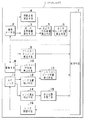
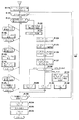
図1から図26は本発明の一実施形態を示したものであり、図1はデジタルカメラの概念的な構成を示すブロック図である。
【0010】
このデジタルカメラ1は、例えば位相差AFにより被写体距離を検出する補助AF手段2と、この補助AF手段2により検出された2つの像の位相に基づいて第1の合焦距離を求める第1の合焦距離算出手段3と、上記2つの像の起伏に基づいて測距誤差を算出する測距誤差算出手段4と、上記第1の合焦距離と上記測距誤差とに基づいて合焦の可能性がありかつ繰出し量が少ない第2の合焦距離を求める第2の合焦距離算出手段5と、この第2の合焦距離算出手段5により求められた第2の合焦距離に基づき後述するレンズを繰り出すための第1のレンズ位置を算出する第1のレンズ位置算出手段6と、被写体像を光電変換して画像信号を出力する撮像手段8と、この撮像手段8により検出された被写体輝度の変化から周期的なフリッカを検出してこのフリッカの影響を受けることなく被写体輝度を安定して検出することができる安定タイミングを検出するフリッカ検出手段と安定タイミング検出手段とを兼ねたフリッカタイミング検出手段9と、上記撮像手段8から出力される画像信号に基づいて該撮像手段8に結像される被写体像のコントラスト評価値(具体的には、コントラスト量)を算出するコントラスト評価値算出手段10と、上記撮像手段8に被写体像を結像するための撮影光学系におけるピント合わせ用のAFレンズ11と、このAFレンズ11のレンズ位置を検出するレンズ位置検出手段12と、後述するレンズ制御手段16により上記AFレンズ11を移動するのに応じてこのレンズ位置検出手段12により検出された複数のレンズ位置とこれら複数のレンズ位置に各対応して上記コントラスト評価値算出手段10により算出された複数のコントラスト評価値とに基づいて上記撮像手段8に結像される被写体像のコントラスト量がピークとなるレンズ位置を算出するコントラストピーク位置算出手段13と、上記AFレンズ11の移動速度を検出するレンズ速度検出手段14と、このレンズ速度検出手段14により検出された移動速度から上記AFレンズ11の停止位置を予想する停止位置予想手段15と、この停止位置予想手段15により予想された停止位置と上記レンズ位置検出手段12により検出されたレンズ位置から目標の繰出し位置までの繰り出し量との差に基づいて上記AFレンズ11を制御して移動させるレンズ制御手段16と、上述したような各要素を含むこのデジタルカメラ1を統括的に制御する制御手段7と、を有して構成されている。
【0011】
このように構成されたデジタルカメラ1の作用は、次のようになっている。
【0012】
まず、上記補助AF手段2により第1のレンズ位置を求めて、この第1のレンズ位置を目標として第1のレンズ繰出しを行う。
【0013】
この第1のレンズ繰出しを行っている最中に、上記コントラスト評価値算出手段10による画像のコントラスト量の検出と、上記レンズ位置検出手段12によるその時のレンズ位置の検出と、を複数回行う。
【0014】
そして、これらの検出結果に基づいて、コントラスト量が最大になる第2のレンズ位置を算出し、この第2のレンズ位置を目標として、第2のレンズ繰出しを行う。
【0015】
AFレンズ11を移動させるときの制御は、上記レンズ速度検出手段14により検出されたレンズ速度に基づき上記停止位置予想手段15が予想停止位置を算出して、レンズ制御手段16が目標の繰出し位置と予想停止位置との差に基づいて行うようになっている。
【0016】
さらに詳細に説明すると、上記第1のレンズ位置は次のようにして求める。
【0017】
上記補助AF手段2は、複数の測距領域について測距を行うことが可能となるように構成されていて、これら複数の測距領域に対して測距を行い、最至近となる第1の合焦距離が得られた測距領域について、測距誤差を算出し、該測距誤差を見込んだ合焦の可能性がある距離の中で繰り出し量の少ない距離である第2の合焦距離を求める。そして、この第2の合焦距離に基づき、第1の繰り出しを行うための第1のレンズ位置を算出する。
【0018】
AFレンズ11の繰り出しは、まず、この第1のレンズ位置を目標として行う。AFレンズ11をこの第1のレンズ位置まで繰り出している最中に、上記補助AF手段2によって最至近となった測距領域についてコントラストAFを行ってさらに正確な合焦位置である第2のレンズ位置を算出し、その後は該第2のレンズ位置を目標として繰り出しを行うことになる。
【0019】
なお、上記撮像手段8も、補助AF手段2による複数の測距領域に各対応する複数の測距領域の撮像が可能となるように構成されている。
【0020】
一般に、レンズ繰り出し機構にはガタが存在し、繰り出した後で繰り込む場合は、そのガタ分以上を移動させてガタ取りをする必要がある。さらに、レンズの移動方向を変える場合には、ブレーキして確実に停止させてから、その後に方向を変えて制御することになるために、ブレーキ時間と戻す時間との両方が必要になり、合焦に至るまでの時間が長くなってしまう。
【0021】
これに対して、このように合焦可能範囲内の繰り出し量の少ない距離に基づいて第1のレンズ位置を算出しているために、真の合焦位置よりも繰り出し過ぎることがなく、方向を変えることなくレンズ位置の制御を行うことが可能となり、ガタ取りの必要もなく、高速に合焦させることが可能となる。
【0022】
なお、上記補助AF手段2は、専用の素子を設けても良いが、撮像手段8の撮像領域以外の領域を利用することも可能である。また、補助AF手段のAF方式としては、後述するように、位相差AFやアクティブAFを用いることができるし、これらに限らずその他の種々の手段を用いることも可能である。
【0023】
また、撮像手段8に結像する被写体像のコントラスト量がピークとなる位置(つまり、合焦位置)の算出は、後で詳しく説明するように、コントラスト量とレンズ位置の関係を正規分布等で近似して算出するようになっている。
【0024】
コントラスト量のピーク位置は、コントラストの変化量がゼロになる位置であるために、AFレンズ11を繰り出しながらコントラスト量を検出する動作を複数回行うことにより、外挿して算出する。
【0025】
また、コントラストAFを行う際には、選択した測距領域について撮像手段8により積分を行う際に、該積分期間の中間のタイミングがフリッカの変化が少ないタイミングとなるように制御されるとともに、さらに、この中間のタイミングにおいてAFレンズ11のレンズ位置も検出するようになっている。これにより、フリッカによる輝度の変動を抑制することが可能となっている。
【0026】
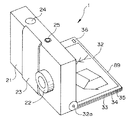
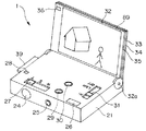
次に、図2はデジタルカメラ1の外観をレンズ側から示す斜視図、図3はデジタルカメラ1をPDA(Personal Digital(Data) Assistants)として使用する際の外観を示す斜視図である。なお、図3は、レンズ側が下を向く配置となっている。
【0027】
このデジタルカメラ1は、本体21の前面側にズーム光学系となっているレンズを内蔵するレンズ鏡筒22が配設されていて、このレンズ鏡筒22は、バリア23が開けられるのに伴って本体21から突出し、撮影可能なワイド端まで駆動されるようになっている。このバリア23を開閉動作させると、それに伴って図示しないバリアスイッチがオン/オフするようになっており、すなわち、バリア23を開けることにより、このデジタルカメラ1がカメラとして動作することになる。
【0028】
また、デジタルカメラ1の上面には、撮影動作を指示入力するためのレリーズスイッチ24や、この上記バリア23が閉じられた状態でこのデジタルカメラ1をPDAとして機能させるための電源オンを行うPDAパワースイッチ25が配設されている。
【0029】
さらに、このデジタルカメラ1の本体21の背面側には、撮影時に被写体を確認するためのファインダ26と、上記レンズの焦点距離を変化させるためのズームスイッチ27と、後述するシート状光源33の輝度を調整するための輝度設定ボリューム31と、このデジタルカメラ1が後述するようにPDAとして動作する際に用いる各部材、すなわち、画像反転スイッチ29と、画像表示モードスイッチ30と、磁石28と、が配設されている。
【0030】
そして、このデジタルカメラ1には、本体21の背面側に対してヒンジ32aにより開閉自在となる表示部89が設けられている。この表示部89は、該本体21の背面側に略沿う閉じ位置となったときに上記ファインダ26やズームスイッチ27を露呈する大きさの薄板状に形成されており、画像を表示するための透過型でなるLCD35と、このLCD35に背面側から照明光を照射するためのシート状光源33と、このシート状光源33から発光された光を上記LCD35に対して均一に拡散するための拡散板34と、が積層されて矩形枠状の支持フレーム32内に保持される構成となっている。
【0031】
この表示部89は、これらLCD35、拡散板34、シート状光源33、により後述する画像表示部材86(図4参照)を構成するとともに、さらにタッチパネル88(図4参照)を有する構成となっており、該タッチパネル88を介して情報入力を行うことができるようになっている。
【0032】
なお、上述では拡散板34とシート状光源33とを用いているが、これらに代えて、例えば有機ELシートなどを用いるようにしても構わない。
【0033】
上述したように、支持フレーム32として矩形枠状のものを用いているために、画像表示部材86およびタッチパネル88を構成する各部材として透光性を有するものを採用すれば、背面側からの外光を光源として利用することが可能となる。これにより、外光が明るい場合には、上記輝度設定ボリューム31を操作して輝度をロー(Low)にするかあるいはオフ(OFF)にすることで、バッテリ消費量を抑制しながら画像を明瞭に観察することが可能となる。
【0034】
上記支持フレーム32の例えば左上角部には磁石36が嵌め込まれており、この表示部89が閉じられた際に、上記本体21の背面側に配設された磁石28と吸着し合い、不用意に表示部89が開いてしまうのを妨げながら、手などで回転力を加えた際には容易に開くように構成されている。
【0035】
また、このデジタルカメラ1には、撮影した画像データを記憶するためのメモリカード39が着脱自在に装着され得るようになっている。
【0036】
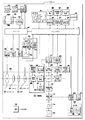
図4は、デジタルカメラ1の主として電気的な構成を示すブロック図である。
【0037】
このデジタルカメラ1は、ズームレンズ44とシャッタ45と絞り46とAFレンズ47とを内蔵する上記レンズ鏡筒22と、上記ズームレンズ44を制御して移動させるズームレンズ制御手段48と、上記シャッタ45を制御して駆動するシャッタ制御手段49と、上記絞り46を制御して駆動する絞り制御手段50と、上記AFレンズ47を移動させる際の駆動源となるLDモータ54とこのLDモータ54を制御して駆動するフォーカスモータ駆動回路52と上記AFレンズ47のレンズ位置を検出するフォーカスレンズ位置検出回路53とを含んでなるフォーカスレンズ制御手段51と、複数の像を形成するレンズ56R,56Lとこれらのレンズ56R,56Lにより形成された複数の像を電気信号に変換する検出手段たるセンサ57とを含んでなるセンサ部55からの出力に基づき位相差AFを行う位相差AF手段58と、被写体に向けて照明光を照射するストロボ発光部59と、このストロボ発光部59に発光電力を供給するストロボメインコンデンサ60と、このストロボメインコンデンサ60への充電や上記ストロボ発光部59への放電を後述するサブCPU42や位相差AF手段58の出力に基づき制御することにより発光を制御するストロボ充電発光制御手段61と、上記ズームレンズ制御手段48、シャッタ制御手段49、絞り制御手段50、フォーカスレンズ制御手段51、位相差AF手段58、ストロボ充電発光制御手段61から必要に応じて情報等を取得しながらこれらを制御するサブCPU42と、上記ズームレンズ44およびAFレンズ47により結像される被写体像を光電変換して画像信号を出力する撮像素子65と、この撮像素子65における撮像領域を指定するための撮像領域指定手段66と、上記撮像素子65から出力されるアナログの画像信号をデジタルの画像データに変換するA/D回路67と、このA/D回路67の出力に基づいて上記撮像素子65のゲイン調整を行う信号レベル制御手段68と、上記A/D回路67から出力される画像データを記憶するメモリ71と、このメモリ71に記憶された画像データを画像処理する画像処理回路72と、この画像処理回路72により処理された画像データを圧縮する画像圧縮手段73と、この画像圧縮手段73により圧縮された画像データを上記メモリカード39に記録するメモリI/F74と、このメモリI/F74の制御により画像データを記憶するための上記メモリカード39と、上記メモリ71に記憶された画像データを読み出して被写体の輝度を検出する被写体輝度検出手段たる輝度検出手段76と、この輝度検出手段76により検出された輝度に基づきフリッカを検出して該フリッカによる影響を受けることのないタイミングを検出するフリッカタイミング検出手段77と、このフリッカタイミング検出手段77により検出されたタイミングによって上記撮像素子65による撮像やA/D回路67によるデジタル化を行わせるタイミング発生回路69と、上記メモリ71に記憶された画像データを読み出してコントラスト評価値(例えばコントラスト量)を算出するコントラスト評価値算出手段78と、このコントラスト評価値算出手段78の出力に基づきコントラスト評価値の微分を算出するコントラスト評価値微分手段79と、このコントラスト評価値微分手段79の出力に基づき合焦位置を予想する合焦位置予想手段80と、上記コントラスト評価値算出手段78の出力に基づき例えば山登りAFを行うことにより合焦検出を行う合焦検出手段81と、上記画像圧縮手段73を介して出力される画像データを表示するために上述した画像表示部材86を制御する画像表示制御手段85と、この画像表示制御手段85により制御されて画像や文字を表示する画像表示部材86とこの画像表示部材86の表示面に沿って配置されているタッチパネル88とを含んでなる表示部89と、上記タッチパネル88からの出力に基づき入力信号を生成して出力するタッチパネル入力手段87と、上記バリア23を開閉する動作に連動してデジタルカメラ1の電源をオン/オフするためのバリアスイッチ、上記レリーズスイッチ24、上記ズームスイッチ27、上記PDAパワースイッチ25、モードスイッチ等を含んでなる操作手段91と、USB(Universal Serial Bus)端子92と、このUSB端子92を制御するためのUSB制御手段93と、無線によりLANに接続するための回路であるIEEE802.b回路94と、このIEEE802.b回路94を制御するためのIEEE802.b制御手段95と、機器同士を無線で接続するためのBluetooth回路96と、このBluetooth回路96を制御するためのBluetooth制御手段97と、後述するメインCPU41を動作させるための処理プログラムやこのデジタルカメラ1に係る各種のデータを記憶するEEPROM98と、このデジタルカメラ1に電力を供給する電池99と、上記サブCPU42と通信を行って該サブCPU42に接続されている各回路を制御するとともに自己に接続されている各回路を含むこのデジタルカメラ1全体を制御するメインCPU41と、を有して構成されている。
【0038】
なお、上記撮像素子65、撮像領域指定手段66、A/D回路67、信号レベル制御手段68、タイミング発生回路69等により、撮像回路64が構成されている。
【0039】
また、上記メモリカード39は、このデジタルカメラ1に対して着脱可能であり、上記電池99も例えば着脱可能に交換され得るようになっている。
【0040】
そして、この図4に示す構成においては、上記図1の構成に対し、センサ部55および位相差AF手段58が補助AF手段2に、メインCPU41が第1の合焦距離算出手段3、測距誤差算出手段4、第2の合焦距離算出手段5、第1のレンズ位置算出手段6、制御手段7、停止位置予想手段15に、撮像素子65が撮像手段8に、フリッカタイミング検出手段77がフリッカタイミング検出手段9に、コントラスト評価値算出手段78がコントラスト評価値算出手段10に、AFレンズ47がAFレンズ11に、フォーカスレンズ位置検出回路53がレンズ位置検出手段12およびレンズ速度検出手段14に、合焦位置予想手段80がコントラストピーク位置算出手段13に、フォーカスモータ駆動回路52がレンズ制御手段16に、それぞれ対応している。
【0041】
図5はコントラストAFに用いられる撮像素子の領域を示す図、図6は位相差AFに用いられるラインセンサの領域を示す図である。
【0042】
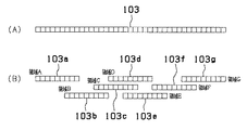
まず、位相差AFを行う際には、図6(A)に示すような細長のラインセンサ103を、図6(B)の符号103a〜103gに示すような領域A〜Gに分割することにより、複数の測距領域について測距を行い、これらの内の最短の距離を示す測距領域に係る測距値と、該測距値の測距誤差と、を考慮して、位相差AFによる測距結果を算出するようになっている。
【0043】
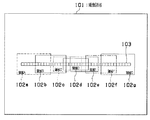
こうして、位相差AFにより求められた測距値に基づき第1のレンズ位置へ繰り出しを行い、さらにコントラストAFを行うことにより正確な合焦位置である第2のレンズ位置を検出して該第2のレンズ位置へ繰り出しを行うが、このときには、図5に示すように、撮像素子65の撮像領域101を、上記ラインセンサ103を分割した領域A〜Gに各対応するように複数の領域A〜G(符号102a〜102g)に分割して、これらの内の上記位相差AFによる測距結果(つまり最至近)を与えた測距領域について、コントラストAFを行うようになっている。
【0044】
なお、撮像素子65は、水平ラインと垂直ラインとを指定することにより任意の画素の読み出しを行うことができるような、例えばCMOS型のセンサとして構成されていて、この図5に示したような領域A〜Gの何れかのみについて読み出しを行うことが可能となっている。
【0045】
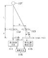
図7は位相差AFの基本的な構成を示す図、図8は位相差AFの出力に基づき第1のレンズ位置を求める手順を説明するための図である。
【0046】
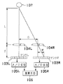
上記センサ部55は、図7に示すように、左右一対に配設されたレンズ104L,104R(図4のレンズ56L,56Rに各対応する)の後方に、上記センサ57に対応する検出手段たる左用及び右用のラインセンサ103L,103Rが各配置されて構成されている。これら一対のレンズ104L,104R同士の間隔である基線長をD、各レンズ104L,104Rから各ラインセンサ103L,103Rまでの光軸方向の距離をf、レンズ104L,104Rから被写体107までの距離をL、左用のラインセンサ103L上の被写体像に対する右用のラインセンサ103R上の被写体像のオフセット量をWとすると、三角形の相似から、L:D=f:Wが成り立つために、被写体距離Lは、
L=D×f/W
として求められる。
【0047】
さらに、上記位相差AF手段58は、各ラインセンサ103L,103Rの出力をそれぞれデジタル信号に変換するA/D手段105L,105Rと、これらのA/D手段105L,105Rによって変換されたデジタル信号に基づき、上記数式を用いて被写体距離Lを求める演算手段106と、を有して構成されている。
【0048】
図8(A)および図8(B)は、コントラストの高い被写体を例に取り、左(L)側のラインセンサ103Lと右(R)側のラインセンサ103Rにおける出力(A/D手段105L,105Rによりデジタル化された出力)の様子を示す図である。図示のように、同一の被写体であると推測されるコントラストの高い被写体は、左右のラインセンサ103L,103Rで結像した位置にシフトが発生していることがわかる。
【0049】
図8(C)は、左(L)側のラインセンサ103Lの出力に対して、右(R)側のラインセンサ103Rの出力を順次シフトさせて、各シフト毎に左右の近似度F(S)を求める様子を示している。
【0050】
ここに、左右の近似度F(S)は、次の数式1に示すように、左(L)側のラインセンサ103Lの出力から、シフトさせた右(R)側のラインセンサ103Rの出力を減算して、その絶対値の総和をとることにより求めるようになっている。
【0051】
【数1】
F(S)=Σ|(L−Rシフト)|
【0052】
こうして求めた近似度F(S)は、例えば図8(D)に示すようになり、図示の例ではシフト量が+3になったところが近似度F(S)の値が最も小さく、この例では「1」(図8(C)を参照)となっている。
【0053】
ここで、近似度が最小となる点(シフト量が+3で近似度が1である点)と、近似度が小さい方から3番目となる点(シフト量が+4で近似度が12である点)とを第1の直線で結び、さらに、この直線の傾きを反転(つまり符号を反転)し、近似度が小さい方から2番目となる点(シフト量が+2で近似度が11である点)にこの符号を反転させた傾きの第2の直線を引き、第1の直線と第2の直線との交点を求めると、この交点のシフト量が、ばらつきを考慮しないシフト量S0であって、第1の合焦距離に対応している。
【0054】
さらに、近似度F(S)の平均値を求め、この平均値と上記シフト量S0における近似度との間の0.3倍を近似度に係るばらつきの範囲として設定する。そして、このばらつきの範囲を示す横の点線と上記第2の直線との交点が、ばらつきを考慮したシフト量S1となり、このシフト量S1に対応する被写体距離が第2の合焦距離となる。従って、この第2の合焦距離に対応するAFレンズ47のレンズ位置を求めることにより、それが第1のレンズ位置となる。
【0055】
ただし、S0とS1の差が所定量Scnt よりも小さい場合、つまり、
|S1−S0|<Scnt
となる場合には、上記S1を採用する代わりに、S1=S0−Scnt を新たにS1として採用して、ばらつきに最低限のリミットを設け、第1のレンズ位置を求めるようにする。
【0056】
また、図9はアクティブAFの基本的な構成を示す図、図10はアクティブAFの出力に基づき第1のレンズ位置を求める手順を説明するための図である。
【0057】
上述では位相差AFにより第1のレンズ位置を求めたが、これに代えて、アクティブAFにより第1のレンズ位置を求めることも可能である。
【0058】
まず、図9を参照して、アクティブAFによる補助AF手段の構成の概要を説明する。
【0059】
アクティブAFによる測距を行う際には、発光制御手段111の制御により、赤外LED110が発光するようになっている。発光された赤外光は、第1のレンズ112を介して被写体107に投射される。
【0060】
照射された被写体107により反射された赤外光は、上記第1のレンズ112に対して所定の基線長Dだけ離間して配設された第2のレンズ113を介して、PSD114に集光される。
【0061】
このPSD114上において、反射された赤外光の集光位置を検出することにより、すなわち、無限遠被写体の結像位置からのずれ量(オフセット量)Wを検出することにより、被写体距離を算出することができる。このオフセット量Wに係る情報を含むPSD114からの出力信号は、受光位置検出手段115に入力されてデジタル信号に変換するなどの処理が行われてから、演算手段116において被写体距離が計算されるようになっている。
【0062】
このとき、一対のレンズ112,113同士の間隔である基線長をD、レンズ113からPSD114までの光軸方向の距離をf、レンズ112から被写体107までの距離をL、無限遠の被写体像に対する実際の被写体像のオフセット量をWとすると、被写体距離Lは、上述した位相差AFのときと全く同様に、
L=D×f/W
として求められる(三角AF)。
【0063】
さらに、このアクティブAFにおいては、PSD114により受光した赤外光の光量を検出することにより、光量に応じた被写体距離も求めるようになっている(光量AF)。
【0064】
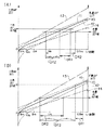
図10(A)は、三角AFおよび光量AFを行って通常の結果が得られたときの様子を示す線図である。
【0065】
この線図においては、三角AFを行ったときの出力値と距離(の逆数)との関係が実線f0により示され、その測距誤差の範囲が点線f1,f2に囲まれた範囲となっている。また、光量AFによる誤差範囲が1点鎖線f3,f4に囲まれた範囲となっている。図示のように三角AFの誤差は遠距離側においてやや拡大する傾向にある一方、光量AFの誤差は近距離側において拡大する傾向となっている。
【0066】
なお、この線図においては、測距値が同じである場合には、三角AFの出力値と光量AFの出力値とが同じとなるようにスケーリングされている。
【0067】
投光した赤外光の大半が被写体107に照射され反射された後に、PSD114に戻ってくる通常の場合の例を示すのが、この図10(A)である。
【0068】
図示のように、三角AFによって求められる誤差を含んだ距離範囲DR1と、光量AFによって求められる誤差を含んだ距離範囲DR2と、は互いに重なっている。
【0069】
このとき本実施形態においては、三角AFによって予想される被写体距離範囲DR1の無限側(点線f1と三角AF出力値との交点であって繰り出し量が小となる第1の距離)と、光量AFによって予想される被写体距離範囲DR2の無限側(1点鎖線f3と光量AF出力値との交点であって繰り出し量が小となる第2の距離)と、の平均をとることにより第3の距離DT2を求め、これを第1のレンズ位置に対応させるようになっている。
【0070】
上述したように、AFレンズ47を遠距離側から駆動する際に、合焦位置を過ぎることなく漸近して行くためには、第1のレンズ位置として、合焦可能な領域内の遠距離側を選択する必要がある。
【0071】
このとき、遠距離では点線に示すように三角AFの誤差が大きく、近距離では1点鎖線に示すように光量AFの誤差が大きいために、両方の無限側を比較してこれらの内のより無限側にある方を単純に選択してしまうと、第3の距離が非常に無限側になって合焦位置から離れてしまうことになる。従って、ここではこれらの平均をとることにより、合焦位置に近い範囲内で無限側にあるような妥当な距離を求めている。
【0072】
一方、図10(B)は、三角AFおよび光量AFを行った結果が重なり合わないときの様子を示す線図である。
【0073】
この例においては、三角AFにより推定される合焦可能性のある距離範囲DR1よりも、光量AFにより推定される合焦可能性のある距離範囲DR2のほうがずっと遠距離側となっており、互いに重畳する部分はない。
【0074】
このような結果は、例えば、投光した赤外光が被写体に一部しか照射されなかった場合や、あるいは、被写体の反射率が想定される平均的な反射率よりも大き過ぎたり小さ過ぎたりする場合などに得られると考えられる。
【0075】
このような場合であっても、上述と同様に、三角AFによって予想される被写体距離範囲DR1の無限側(点線f1と三角AF出力値との交点であって繰り出し量が小となる第1の距離)と、光量AFによって予想される被写体距離範囲DR2の無限側(1点鎖線f3と光量AF出力値との交点であって繰り出し量が小となる第2の距離)との平均をとって第3の距離DT2を求めるようにすれば、妥当な距離を求めることが可能となっている。
【0076】
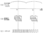
図11は、フリッカの影響を極力受けることのないようにコントラストAFを行うための、撮像素子の積分タイミング等を示すタイミングチャートである。
【0077】
図11(A)に示すように、蛍光灯などの商用電源による照明には、該商用電源が交流であることに起因して、その半周期毎に輝度が変動するものがある。商用電源の周期は、50Hzまたは60Hzの何れかである場合が多く、これらの場合について輝度の変動する周期を計算すると、次のようになる。
・50Hzの場合の周期: 1000/50/2=10.0mS
・60Hzの場合の周期: 1000/60/2=8.333mS
【0078】
従って、輝度がピークとなるタイミングtp 同士の時間間隔は、これらの周期の何れかになる場合が多いと考えられる。
【0079】
被写体輝度検出手段たる輝度検出手段76により、フリッカの影響を受けた被写体の輝度を検出したときに、例えば図11(A)に示したようになったものとする。
【0080】
この輝度検出手段76により検出された被写体輝度の変化に基づき、フリッカ検出手段と安定タイミング検出手段とを兼ねたフリッカタイミング検出手段77が、周期的なフリッカを検出して、該フリッカの影響を受けることなく被写体輝度を安定して検出することができる安定タイミングを検出するようになっている。
【0081】
すなわち、この図11(A)に示すように、輝度の変化は、ピークとなるタイミングtp 付近で最も緩やかであるために、撮像素子65によりコントラストAFを行うときの積分期間が、この輝度変化の緩やかな部分に一致するように行うことが望ましい。このためのタイミングを示すのが図11(B)である。
【0082】
図11(B)は、撮像素子65における上記図5に示した領域A〜Gの内の、選択された何れかの測距領域における各画素の積分期間を示している。
【0083】
選択された測距領域における各画素の積分開始タイミングは、図示のように画素毎に少しずつずれており、各画素について同一期間だけ積分を行った後に、それぞれが異なるタイミングで積分を終了して読み出されるようになっている。
【0084】
このとき、選択領域内において最も早く積分が開始された画素の積分開始タイミングと、該選択領域内において最も遅く積分が終了した画素の積分終了タイミングと、の中間にフリッカ輝度のピークタイミングtp が位置するように積分を行うよう制御することで、フリッカによる輝度変化の影響を最小限に抑制するようにしている。
【0085】
さらに、上記フォーカスレンズ位置検出回路53内に設けられていて、AFレンズ47が繰り出されるのに応じてパルスを出力するLDPI(レンズドライブフォトインタラプタ)のカウント値を、図11(C)に示すように、このピークタイミングtp において求めるようにしている。
【0086】
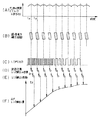
図12は、フリッカに対応して読み出される撮像素子65の出力に基づき、測距計算やレンズ繰り出しを行うタイミングを示すタイミングチャートである。
【0087】
時間軸方向のスケールはやや異なるものの、図12(A)は上記図11(A)と、図12(B)は上記図11(B)と、図12(C)は上記図11(C)と、それぞれほぼ同一の出力等を示している。
【0088】
また、撮像素子65から読み出された測距領域の信号に基づいて、図12(D)に示すようなタイミングで測距計算を行うとともに、測距結果と読み出したLDPIのカウント値とからAFレンズ47を繰り出すパルス数を更新して、更新されたパルス数に基づき図12(E)に示すようなタイミングでフォーカスモータ駆動回路52がLDモータ54を制御することにより、レンズ繰り出しが行われる。
【0089】
このような制御を行ったときのAFレンズ47の繰り出し量の一例を示すのが図12(F)である。
【0090】
図示の例においては、最初は位相差AFにより検出された第1のレンズ位置に向けて等速でレンズ繰り出しを行っているが、該第1のレンズ位置に近づいたところで一旦減速している。このような動作を行っている間にコントラストAFにより第2のレンズ位置が検出されるために、再びやや加速して繰り出し、該第2のレンズ位置に近づいたところでまた減速している。
【0091】
なお、ここではフリッカの周期毎にコントラストAFによる測距計算を行っているが、例えば撮像素子65の測距領域の画素数が多い場合などには該フリッカ周期よりも長い時間を測距計算に要することがあり得る。このような場合には、フリッカ周期の適宜の整数倍を周期として、コントラストAFを行うようにすれば良い。
【0092】
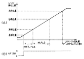
図13は、LDPIのパルス数に対するAFレンズ47の繰り出し量の関係およびAFスイッチの変化タイミングを示すタイミングチャートである。
【0093】
AFレンズ47が最も繰り込んだ位置にあるときに、上記LDモータ54に駆動パルスの供給を開始すると、図13(A)に示すように、あそびの部分を経た後に、AFレンズ47が実際に繰り出し始められる。
【0094】
AFレンズ47が、ある程度まで繰り出されると、図13(B)に示すように、上記フォーカスレンズ位置検出回路53に設けられたAFスイッチ(AFSW)が、ロー(L)からハイ(H)に変化する。AFスイッチが変化したこの位置が、AFレンズ47を繰り出す際の基準位置となる。
【0095】
この基準位置から所定のリセットパルス数RST_PLSだけ繰り出したところが無限位置となり、この無限位置からさらに目標パルス数M_PLSだけ繰り出したところが目標位置となる。
【0096】
また、この目標位置を過ぎてさらに繰り出しを行うと、至近位置を経て、機構的にそれ以上はAFレンズ47を繰り出すことができない位置に到達して、多少のあそびの部分を経た後に、それ以上はLDモータ54を駆動することができない状態になる。
【0097】
このように、AFスイッチが変化する位置を基準として無限位置を決定し、この無限位置からの目標パルス数を与えることにより、目標位置に到達するようになっている。
【0098】
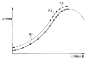
図14は、合焦位置付近におけるAFレンズ47の繰り出し量とコントラスト量(AF評価値)との関係を示す線図である。
【0099】
コントラスト量は、合焦位置から無限側および至近側に離れるに従って小さな値をとり、合焦位置においてピーク(極大)となるようなカーブをなす。レンズ繰り出しを行ってこのようなカーブ上を辿る際の、上述したフリッカの輝度ピークを与えるピークタイミングtp に合わせた撮像素子65の積分タイミングを丸印で付している。
【0100】
図示のように、カーブに沿った領域R1においては、最初は高速な所定の繰り出し速度でAFレンズ47が繰り出されているが、位相差AFに基づき算出された第1のレンズ位置に近づくと、繰り出し速度がやや遅くなって丸印の間隔が少し狭くなっている。
【0101】
その後のカーブに沿った領域R2においては、第1のレンズ位置にさらに近接するに従って、繰り出し速度がゆっくりになって停止しかかっている。
【0102】
丸印を付したタイミングにおいて行われたコントラストAFにより、第2のレンズ位置が算出されると、目標が更新されるために、カーブに沿った領域R3に示すように、再びやや加速され、第2のレンズ位置に向かうにつれて再び減速してコントラスト量のピークとなる第2のレンズ位置に到達したところでAFレンズ47の駆動を停止するようになっている。
【0103】
なお、第2のレンズ位置は、丸印に示したようにコントラストAFを行う毎に更新されて、より高い精度で合焦位置を設定するようになっている。
【0104】
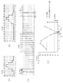
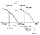
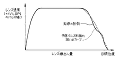
図15はLDPIのパルス幅が示すレンズ速度のときにどのくらいの繰り出し量でAFレンズ47が停止するかを示す線図、図16は目標位置に到達するまでのレンズ速度の変化の様子を示す線図、図17はレンズ繰り出しを開始してから目標位置に到達するまでのレンズ速度の変化の様子を示す線図である。
【0105】
LDモータ54は、単位時間当たりに印加されるパルス数が多ければ速い速度で回転し、逆に、パルス数が少なければ遅い速度で回転するために、パルス幅とレンズ速度とは逆比例する関係にある。
【0106】
従って、図15においては、縦軸方向の座標が大きい(つまりパルス幅が大きい)ほどレンズ速度が遅く、縦軸方向の座標が小さい(つまりパルス幅が小さい)ほどレンズ速度が早いことを示している。
【0107】
このとき、予想パルス制御を行ったときの狙いの繰り出し量は、実線で示すような曲線を中心として点線で示すような2本の曲線に挟まれる程度の範囲となる。この曲線は、当然にして、レンズ速度が遅いときには繰り出し量が小さく(LDPIパルス数が少ない)、レンズ速度が速いときには繰り出し量が大きい(LDPIパルス数が多い)曲線となっていて、運動エネルギーが速度の2乗に比例するのを反映し、図示のようなカーブの曲線となっている。
【0108】
また、下側の点線で示すカーブの下の領域は、LDモータ54をモータブレーキのみにより制御したときの停止するまでの繰り出し量に係る領域、一方、上側の点線で示すカーブの上の領域は、LDモータ54をモータオープン制御したときの停止するまでの繰り出し量に係る領域となっている。
【0109】
このようなレンズ速度と繰り出し量との関係を有するAFレンズ47を実際に停止させるときの制御例を示すのが図16である。この図16においては、レンズ速度に対する停止までのパルス数が左側に、移動パルス数とレンズ速度との関係が右側に、それぞれ示されている。
【0110】
目標位置に停止するためには、右側の実線で示すような制御を行うのが理想であるが、実際には点線に示すように目標位置に到達するまでの残りパルス数と現在のレンズ速度とを見比べながら、モータオープン制御やモータブレーキ制御を行って調整しながら停止を行う。
【0111】
点線で示す実際の制御曲線上における図示の点Aを例にとると、次のように制御を行うことになる。
【0112】
まず、点Aの基準位置から繰り出したパルス数をCT_PLSとし、さらに該点Aにおけるレンズ速度をvA とする。
【0113】
この点Aおける目標位置までの残りパルス数は、基準位置から目標位置までのパルス数が上記図13(A)に示したように、M_PLS+RST_PLSであることから、M_PLS+RST_PLS−CT_PLSとなる。
【0114】
一方、レンズ速度vA のときに理想の制御を行った場合に予想される停止までのパルス数は、図16の左側を参照すればわかるように、Y_PLSであり、オープン制御をした場合にはこれに加えてOPN_PLSだけのパルス数が増加する。
【0115】
従って、これらを比較することにより、つまり次の量、
Y_PLS-(M_PLS+RST_PLS-CT_PLS)+OPN_PLS
を評価することにより、現在のレンズ位置およびレンズ速度で目標位置に停止するか、目標位置の手前で停止するか、目標位置を越えて停止するかを予想することが可能である。
【0116】
この図16に示す例においては、
Y_PLS-(M_PLS+RST_PLS-CT_PLS)+OPN_PLS < 0
となる(すなわち、実線で示すような理想の制御を行った場合よりも、点Aはレンズ速度が小さい)ために、目標位置よりも手前で停止してしまうと予想される。そこで、LDモータ54を正転させて、理想の制御に沿うように調整を行うことになる。
【0117】
こうして、最も繰り込んだ位置からAFレンズ47を繰り出して目標位置に停止しようとするときの、繰り出し量に対するレンズ速度の変化の様子の一例を示すのが図17である。この図17においては、理想の制御が点線で示され、実際の制御が実線で示されていて、狙いとする理想の制御曲線に対して、ある程度の幅をもちながら実際の制御が行われている。
【0118】
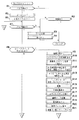
図18および図19は、デジタルカメラ1のメイン動作を示すフローチャートである。
【0119】
上述したように、このデジタルカメラ1は、バリア23が開いているときはカメラとして機能し、バリア23が閉じているときにPDAパワースイッチ25がオンされるとPDAとして機能するように構成されていて、ここではカメラとして動作するときの流れについて説明する。
【0120】
すなわち、この動作が開始されると、まず、バリア23が開になっているか否かを判断する(ステップS1)。
【0121】
ここで、バリア23が閉じられている場合には、レンズ鏡筒22が沈胴しているか否かを判断し(ステップS2)、沈胴していない場合には、レンズ鏡筒22をズーム駆動して沈胴させ収納状態にする処理を行い(ステップS3)、LCD35の表示をオフにする(ステップS4)。そして、このステップS4が終了するか、上記ステップS2においてレンズ鏡筒22が沈胴している場合には、このデジタルカメラ1の動作を停止する。
【0122】
また、上記ステップS1において、バリア23が開いている場合には、ズームをワイドにして撮影可能状態にしてから(ステップS5)、4分タイマをスタートさせる(ステップS6)。
【0123】
そして、バリア23が開のままであるかを判断し(ステップS7)、閉じになっている場合には上記ステップS3へ行く。
【0124】
また、バリア23が開のままである場合には、レリーズスイッチ24が操作されたか否かを判断する(ステップS8)。
【0125】
ここで、レリーズスイッチ24が操作されている場合には、撮像を行うための一連の処理を行う。
【0126】
すなわち、まず撮像回路64をオンにして(ステップS9)、サブCPU42へ外光測距(つまり、上記例においては位相差AFによる測距)要求を出力し(ステップS10)、上記信号レベル制御手段68により撮像素子65のゲイン調整(測光)を行う(ステップS11)。
【0127】
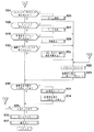
次に、上記フリッカタイミング検出手段77により商用周波数の輝度変化を測定して、測距タイミングを決定する(ステップS12)。
【0128】
そして、メインCPU41は、サブCPU42から外光測距情報を入手して(ステップS13)、測距しながらピント合わせを行うサブルーチン「LDRIV_M」を実行する(ステップS14)。このサブルーチンの詳細については、後述する。
【0129】
続いて、撮像素子65により撮像を行い(ステップS15)、上記画像処理回路72により得られた画像データに関して欠陥画素の補正を行うとともに(ステップS16)、ホワイトバランス補正を行った後に(ステップS17)、上記画像圧縮手段73により画像データ圧縮を行う(ステップS18)。
【0130】
そして、画像表示をオンにして上記表示部89に画像を表示するとともに(ステップS19)、圧縮された画像ファイルをメモリI/F74を介してメモリカード39に保存する(ステップS20)。
【0131】
その後、撮像駒数をカウントアップし(ステップS21)、4分タイマをスタートするとともに(ステップS22)、画像表示用の10秒タイマを再スタートする(ステップS23)。
【0132】
また、上記ステップS8において、レリーズスイッチ24が操作されていない場合には、次に、ズームアップ(ZU)スイッチまたはズームダウン(ZD)スイッチが操作されたか否かを判断し(ステップS24)、何れかが操作されている場合には、該操作に応じてズーム制御を行い(ステップS25)、上記ステップS22へ行く。
【0133】
ズームアップスイッチとズームダウンスイッチの何れも操作されていない場合には、次に、モードスイッチが操作されたか否かを判断し(ステップS26)、操作されている場合には、その操作に応じてモード変更を行い(ステップS27)、上記ステップS22へ行く。
【0134】
ここで、モードスイッチが操作されていない場合には、次に、画像表示スイッチが操作されているか否かを判断し(ステップS28)、操作されている場合には、画像表示を行い(ステップS29)、上記ステップS22へ行く。
【0135】
また、画像表示スイッチが操作されていない場合には、次に、画像アップダウンスイッチが操作されたか否かを判断し(ステップS30)、操作されている場合には、その操作に応じて、1つ前、または1つ後の撮影画像を表示し(ステップS31)、上記ステップS22へ行く。
【0136】
一方、画像アップダウンスイッチが操作されていない場合、または、上記ステップS23が終了した場合には、画像表示時間の10秒が経過したかを判断して(ステップS32)、経過している場合には画像表示をオフし(ステップS33)、画像表示用の10秒タイマを停止してから(ステップS34)、また、画像表示時間の10秒が経過していない場合にはそのまま、4分が経過したか否かを判断する(ステップS35)。
【0137】
ここで、まだ4分に満たない場合には上記ステップS7へ行き、一方、4分が経過している場合には、ズームをワイドにする処理を行い(ステップS36)、表示部89の表示をオフにして(ステップS37)、このデジタルカメラ1の動作を停止する。ここでの動作停止は、クロック(原振)も停止して、消費電流をほぼ0となるようにする処理を行う。また、この停止状態からは、バリア23が操作されたり、電池99を脱着されたときに復帰するようになっている。
【0138】
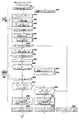
次に、図20および図21は、測距しながらピント合わせを行うときのサブルーチン「LDRIV_M」の詳細を示すフローチャートである。
【0139】
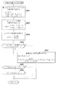
このサブルーチンは、大まかに行って、フリッカ検出用のゲイン調整を行い(ステップS41〜ステップS46)、フリッカの輝度振動の少ないタイミングを検出し(ステップS47〜ステップS63)、AFスイッチが変化するまでの制御(AFのコントラストを測定)を行い(ステップS64〜ステップS71)、その後にコントラスト検出によるフィードバック制御(カーブ制御)を行って(ステップS72〜ステップS85)、AFレンズを所望の位置に停止させるものであり、実際のレンズ制御はサブCPU42により行われる。
【0140】
すなわち、動作が開始されると、まず、AF領域の露光時間(積分期間)が1msよりも小さいか否かを判断し(ステップS41)、大きい場合には上記信号レベル制御手段により撮像素子65のゲインを上げて露光時間(積分期間)が1ms以内に収まるようにする(ステップS42)。
【0141】
次に、タイミング合わせ用タイマ(AFタイマ)をスタートさせて(ステップS43)、上記撮像領域指定手段66により指定されたAF領域について撮像を行う(ステップS44)。
【0142】
そして、AF領域の輝度を合計して、AF_SUM(n)に代入し(ステップS45)、nが25に達したか否か、つまり、25回撮像を繰り返して行ったか否かを判断する(ステップS46)。
【0143】
ここで、25回に満たない場合には、上記ステップS44へ行って上述したようなAF領域の撮像を繰り返し、25回に達したところで、サブCPU42へレンズ制御の開始要求を送信する(ステップS47)。
【0144】
そして、輝度の変動の割合を、次の数式2に示すように算出して、AF_HENKAに代入する(ステップS48)。
【0145】
【数2】
AF_HENKA=Σ|{AF_SUM(n)-AF_SUM(n)の平均}|/ΣAF_SUM(n)
ここに、和(Σ)は変数nについてとっている。
【0146】
そして、算出したAF_HENKAが所定値よりも大きいか否かを判断し(ステップS49)、所定値以下である場合には、AFタイマを9.167msでパルス出力するように設定する(ステップS63)。
【0147】
また、所定値よりも大きい場合には、AF領域の輝度変化率を次の数式3に示すように算出して、AF_SUM_D(n)に代入する(ステップS50)。
【0148】
【数3】
AF_SUM_D(n)={AF_SUM(n+1)-AF_SUM(n)}/AF_SUM(n)
【0149】
次に、nが24に達したか否かを判断し(ステップS51)、まだ24に達していない場合には、このステップS50の処理を繰り返して行う。
【0150】
こうして、nが24に達したところで、変数mに1を設定してから(ステップS52)、AF_SUM_D(n)≧0かつAF_SUM_D(n+1)≦0が満たされているか否かを判断する(ステップS53)。
【0151】
ここで、満たされている場合には、輝度のピークタイミングを次の数式4に示すように算出して、T_AF_PK(m)に代入する(ステップS54)。
【0152】
【数4】
T_AF_PK(m)=n+AF_SUM_D(n)/{AF_SUM_D(n+1)-AF_SUM_D(n)}
【0153】
そしてmをインクリメントする(ステップS55)。
【0154】
このステップS55が終了するか、または上記ステップS53が満たされていない場合には、nが24に達したか否かを判断し(ステップS56)、まだ24に達していない場合には、上記ステップS52へ行って、上述したような処理を繰り返して行う。
【0155】
こうして、nが24に達したところで、T_AF_PK(n+1)−T_AF_PK(n)が10.0msとほぼ等しいか否か、つまり周波数50Hzの周期の半分にほぼ等しいか否かを判断し(ステップS57)、ほぼ等しい場合には、AFタイマカウント値が(10.0msの倍数−AFの撮像時間(積分期間)の半分)の時間になるまで待ってから(ステップS58)、AFタイマを10.0msでパルス出力するように設定する(ステップS59)。
【0156】
また、上記ステップS57において、10.0msと異なる場合には、次に、T_AF_PK(n+1)−T_AF_PK(n)が8.333msとほぼ等しいか否か、つまり周波数60Hzの周期の半分にほぼ等しいか否かを判断する(ステップS60)。
【0157】
ここで、ほぼ等しい場合には、AFタイマカウント値が(8.333msの倍数−AFの撮像時間(積分期間)の半分)の時間になるまで待ってから(ステップS61)、AFタイマを8.333msでパルス出力するように設定する(ステップS62)。
【0158】
一方、上記ステップS60において、8.333msと異なる場合には、上記ステップS63へ行って、上述したように、AFタイマを9.167msでパルス出力するように設定する。なお、この9.167msは、10.0msと8.333msとの平均値となっている。
【0159】
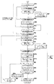
こうして、上記ステップS59、ステップS62、ステップS63の何れかによりAFタイマの設定が行われたら、変数nを0にセットしてから(ステップS64)、AF領域の撮像(積分)を開始する(ステップS65)。
【0160】
そして、撮像(積分)の中間のタイミングであるか否かを判断して(ステップS66)、そうである場合には、サブCPU42からCT_PLS(無限位置から繰り出したパルス数)を受信して、それをCT_PLS(n)に代入する(ステップS67)。
【0161】
このステップS67が終了するか、あるいは上記ステップS66において撮像(積分)の中間のタイミングでないと判断された場合には、AF領域の撮像が終了したか否かを判断し(ステップS68)、終了するまでは上記ステップS65へ行ってAF領域の撮像を継続して行う。
【0162】
こうして、AF領域の撮像が終了したと判断されたところで、コントラストの評価値をAF_CON(n)に代入し(ステップS69)、AFタイマ出力が反転したかを判断する(ステップS70)。
【0163】
ここで反転した場合には、上記ステップS65へ行って上述したような処理を繰り返して行い、一方、反転していない場合には、CT_PLSが正であるか否か、つまりAFスイッチが変化したか否かを判断する(ステップS71)。
【0164】
変化するまでは、上記ステップS70へ行き、また、変化した場合には、次に、AFタイマ出力が反転するまで待機する(ステップS72)。
【0165】
こうして、タイマ出力が反転したことが確認されたところで、nをインクリメントしてから(ステップS73)、AF領域の撮像(積分)を開始する(ステップS74)。
【0166】
そして、撮像(積分)の中間のタイミングになったか否かを判断して(ステップS75)、中間のタイミングになったところで、サブCPU42からCT_PLSを受信して、それをCT_PLS(n)に代入する(ステップS76)。
【0167】
このステップS76が終了するか、あるいは上記ステップS75において、撮像(積分)の中間のタイミングでない場合には、AF領域の撮像が終了したか否かを判断し(ステップS77)、終了するまでは上記ステップS74へ行って上述したような処理を繰り返して行う。
【0168】
こうして、AF領域の撮像が終了した場合には、コントラスト評価値算出手段78によりコントラストの評価値を計算して、それをAF_CON(n)に代入し(ステップS78)、予想される合焦パルス数を計算して、それをM2_PLS(n)に代入する(ステップS79)。
【0169】
そして、M2_PLS(n)がM1_PLSよりも大きいか否かを判断して(ステップS80)、大きくない場合には、AFタイマ出力が反転するのを待機し(ステップS84)、反転したところで上記ステップS73へ行って上述したような処理を行う。
【0170】
また、M2_PLS(n)がM1_PLSよりも大きい場合には、次の数式5によりZZを算出する(ステップS81)。
【0171】
【数5】
ZZ=M2_PLS(n)-(RST_PLS+CT_PLS+OPN_PLS)
【0172】
そして、算出したZZが0以下であるかを判断し(ステップS82)、0よりも大きい場合には、M2_PLS(n)をサブCPU42へ送信してから(ステップS83)、上記ステップS84へ行ってAFタイマの出力が反転するのを待機する。
【0173】
このように、フリッカの安定したタイミングを測るためのタイマであるAFタイマに合わせてコントラストAFによる測距を行い、新しく算出した予想の合焦パルス数M2_PLS(n)をサブCPU42に送ってフィードバック制御を行うようになっている。
【0174】
また、上記ステップS82において、ZZが0以下になっている場合には、LD制御終了コードをサブCPU42へ送信してから(ステップS85)、このサブルーチンを抜けて、上述したメインルーチンに復帰する。
【0175】
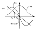
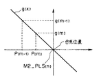
ここで、上記ステップS79における予想の合焦パルスを計算する際の原理について、図23と図24を参照して説明する。図23は合焦位置近傍においてコントラスト量を正規分布により近似した曲線等を示す図、図24は複数のコントラストAF結果を用いて合焦位置を算出するための直線g(x)を示す図である。
【0176】
まず、AFレンズ47の駆動量xに対する、撮像素子65に結像される被写体像のコントラスト量の変化の仕方が、次の数式6に示すように、正規分布の関数F(x)になるものと仮定(近似)する(図23参照)。
【0177】
【数6】

なお、この座標系においては、x=0となる点がコントラスト量のピーク、つまり合焦位置となるように設定されている。
【0179】
次に、このF(x)を微分した関数をf(x)とすると、次の数式7により与えられる(図23参照)。
【0180】
【数7】
このf(x)をF(x)で割ったものをg(x)とすると、次の数式8に示すように合焦位置x=0を通る一次関数となる(図23参照)。
【0182】
【数8】
従って、このg(x)を通る2点を求めることにより、このg(x)を決定することができ、決定したg(x)を用いれば合焦位置を算出することが可能となる。
【0184】
ただし、g(x)の分母であるF(x)は、xの絶対値が大きくなると急速に小さくなってしまうために、誤差が増大すると考えられる。そこで、F(x)の変曲点(つまり、f(x)のピーク(極大)位置)となるx=a0 を過ぎたところで、g(x)を決定するための2点a1 ,a2 を求めるようにして、誤差を抑制するようにしている。すなわち、必要な精度でg(x)を算出するためにはコントラスト評価値に係るF(x)がピークとなるx=0の近傍において算出することが望ましく、このような近傍の範囲として、ここでは上記g(x)の極大値と極小値との間を採用している。
【0185】
また、上記駆動量xは、具体的には、例えばパルス駆動したときのパルス数が該当する。
【0186】
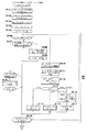
図22は、上記図21のステップS79における予想の合焦パルスを計算する処理を示すフローチャートである。
【0187】
この動作が開始されると、繰出パルスの配列P(m)とコントラストの配列F(m)とを作成する(ステップS91)。すなわち、変数mをインクリメントして、取得した繰出パルスCT_PLS(n)をP(m)に代入するとともに、取得したコントラストAF_CON(n)をF(m)に代入する。このサブルーチンが呼ばれる都度にこの操作が繰り返されるために、P(m)とF(m)は配列として作成されることになる。
【0188】
同様にして、コントラストの微分の配列f(m)を、次の数式9に示すように作成する(ステップS92)。
【0189】
【数9】
さらに、次の数式10に示すようにf(m)をF(m)で割ることにより、g(m)の配列を作成する(ステップS93)。
【0191】
【数10】
g(m)=f(m)/F(m)
【0192】
そして、f(m)は自己のピークを既に越えているかをピークフラグが1になっているか否かにより判断し(ステップS94)、まだ、ピークを越えていない場合には、f(m)が1つ前の配列要素であるf(m−1)よりも小さいか否かを判断することにより、今回計算したf(m)によりピークを越えているかを判断する(ステップS95)。
【0193】
ここで、まだf(m)がf(m−1)以上である場合には、まだピークを越えていないとしてそのままリターンし、f(m)がf(m−1)よりも小さい場合には、ピークフラグに1を設定してから(ステップS96)、リターンする。
【0194】
一方、上記ステップS94において、f(m)がピークを越えていると判断された場合には、次の数式11により直線近似を行って(図24参照)、合焦位置M2_PLS(n)を算出してから(ステップS97)、その後にリターンする。
【0195】
【数11】
こうして、コントラスト量を正規分布で近似して、該コントラスト量とコントラスト量の微分との比が直線になるのを利用することにより、合焦位置を的確に算出することができる。
【0197】
さらに、微分のピーク位置を過ぎたところで直線近似を行っているために、高い精度で合焦位置を求めることが可能となる。
【0198】
図25および図26は、サブCPU42におけるピント合わせのサブルーチン「LDRIV_SB」の動作を示すフローチャートである。
【0199】
このサブルーチンにおいては、初期値の設定等を行った後に、AFSWがハイ(H)になるまではAFSWから第1のレンズ位置までのパルス数(RST_PLS+M1_PLS)で停止する速度の等速制御を行い(ステップS106〜ステップS118)、AFSWがハイ(H)になった後は第2のレンズ位置になるまでカーブ制御を行う(ステップS120〜ステップS133)ようになっている。
【0200】
このとき、メインCPU41からの通信により第2のレンズ位置が更新された場合には、その更新されたレンズ位置で停止するように制御している。
【0201】
すなわち、この動作が開始されると、上記EEPROM98から、AFスイッチが変化した時点から無限位置までのLDPIパルス数を読み出して、RST_PLSに代入する(ステップS101)。
【0202】
さらに、EEPROM98からオープン制御するパルス数を読み出して、OPN_PLSに代入する(ステップS102)。
【0203】
その後、無限位置から停止までの目標パルス数M_PLSとして、外光測距により求めた無限位置からピント位置までのパルス数M1_PLSを代入して(ステップS103)、さらに、無限位置から繰り出したパルス数CT_PLSに0をセットする(ステップS104)。
【0204】
その後に、LDモータ54を正転して(ステップS105)、LDPIが変化したかを検出する(ステップS106)。
【0205】
ここで、LDPIの変化が検出された場合には、LDPIパルス幅を測定して、その結果をW_PLSに代入し(ステップS110)、さらに、このW_PLSから停止までのパルス数を予想して、その結果をY_PLSに代入する(ステップS111)。
【0206】
そして、Zを次の数式12により算出する(ステップS112)。
【0207】
【数12】
Z=Y_PLS−(RST_PLS+M_PLS)
【0208】
こうして、算出したZの値を判断して(ステップS113)、Zが正である場合には、M1_PLSよりも繰り出し過ぎるとして、LDモータ54にブレーキをかける処理を行う(ステップS114)。
【0209】
また、上記ステップS113において、Zが0以下で−OPN_PLSよりも大きい場合には、LDモータ54をオープン制御する処理を行う(ステップS115)。
【0210】
さらに、上記ステップS113において、Zが−OPN_PLS以下である場合には、M1_PLSよりも手前で止まり過ぎるとして、(RST_PLS+M_PLS)に応じたモータ電圧を設定してから(ステップS116)、LDモータ54を正転する処理を行う(ステップS117)。
【0211】
一方、上記ステップS106において、LDPIが変化していないと判断された場合には、所定時間LDPIが変化していないかを判断し(ステップS107)、所定時間に達している場合には、モータ電圧を所定電圧だけ上げて設定し(ステップS108)、LDモータ54を正転させる(ステップS109)。こうして、LDPIが変化しない場合には、ここでモータ電圧を所定電圧ずつ段階的に上げて再起動を行っている。
【0212】
上記ステップS107において所定時間内にLDPIが変化した場合、上記ステップS109が終了した場合、または上記ステップS114、ステップS115、ステップS117の何れかが終了した場合には、AFスイッチがロー(L)からハイ(H)に変化したか否かを判定し(ステップS118)、変化するまでは上記106へ行って、上述したような処理を繰り返して行う。
【0213】
このようなステップS106からステップS118のループにおいて、CT_PLS要求の割り込みがあった場合には、C_PLS(=0)をメインCPU41に送信する割り込み処理を行うようになっている(ステップS141)。
【0214】
上記ステップS118において、AFスイッチがロー(L)からハイ(H)に変化したことが検出された場合には、CT_PLSカウント用カウンタをスタートして(ステップS119)、LDPIが変化したかを検出する(ステップS120)。
【0215】
ここで、LDPIの変化が検出された場合には、カウンタのカウント値をCT_PLSに代入するとともに(ステップS124)、LDPIパルス幅を測定して、その結果をW_PLSに代入し(ステップS125)、さらに、このW_PLSから停止までのパルス数を予想して、その結果をY_PLSに代入する(ステップS126)。
【0216】
そして、Zを次の数式13により算出する(ステップS127)。
【0217】
【数13】
Z=Y_PLS−(RST_PLS+M_PLS−C_PLS)
【0218】
こうして、算出したZの値を判断して(ステップS128)、Zが正である場合には、M_PLSよりも繰り出し過ぎるとして、LDモータ54にブレーキをかける処理を行う(ステップS129)。
【0219】
また、上記ステップS128において、Zが0以下で−OPN_PLSよりも大きい場合には、LDモータ54をオープン制御する処理を行う(ステップS130)。
【0220】
さらに、上記ステップS128において、Zが−OPN_PLS以下である場合には、M_PLSよりも手前で止まり過ぎるとして、(RST_PLS+M_PLS−CT_PLS)に応じたモータ電圧を設定してから(ステップS131)、LDモータ54を正転する処理を行う(ステップS132)。
【0221】
一方、上記ステップS120において、LDPIが変化していないと判断された場合には、所定時間LDPIが変化していないかを判断し(ステップS121)、所定時間に達している場合には、モータ電圧を所定電圧だけ上げて設定し(ステップS122)、LDモータ54を正転させる(ステップS123)。上述と同様に、ここでは、モータ電圧を所定電圧ずつ段階的に上げて再起動を行っている。
【0222】
上記ステップS121において所定時間内にLDPIが変化した場合、上記ステップS123が終了した場合、または上記ステップS129、ステップS130、ステップS132の何れかが終了した場合には、LD制御終了コードを受信したか否かを判断し(ステップS133)、受信するまでは上記ステップS120へ行って、上述したような処理を繰り返して行う。
【0223】
このようなステップS120からステップS133のループにおいて、CT_PLS要求の割り込みがあった場合には、C_PLSをメインCPU41に送信する割り込み処理を行い(ステップS142)、M2_PLS要求の割り込みがあった場合には、M2_PLSを受信して(ステップS143)このM2_PLSをM_PLSに代入する処理を行い(ステップS144)、LD終了要求の割り込みがあった場合には、LD制御終了コードを受信する処理を行う(ステップS145)ようになっている。
【0224】
上記ステップS133において、LD制御終了コードを受信した場合には、LDモータ54にブレーキを掛けて(ステップS134)、30ms待機し(ステップS135)、LDモータ54をオープンにしてから(ステップS136)、リターンするようになっている。
【0225】
このような実施形態によれば、登り降りをすることなく、コントラスト量のピークに向けて登るだけの一方向のレンズ繰出しによりピント合わせを行うことができるために、正確なAF動作を高速に行うことが可能となる。
【0226】
なお、本発明は上述した実施形態に限定されるものではなく、発明の主旨を逸脱しない範囲内において種々の変形や応用が可能であることは勿論である。
【0227】
[付記]
以上詳述したような本発明の上記実施形態によれば、以下のごとき構成を得ることができる。
【0228】
(1) 被写体距離を検出する補助AF手段と、
被写体像を光電変換して所定の積分期間だけ積分した後に画像信号として出力する撮像手段と、
この撮像手段に結像される被写体像のピントを合わせるためのAFレンズと、
上記撮像手段から出力される画像信号に基づいて該撮像手段に結像される被写体像のコントラスト評価値を算出するコントラスト評価値算出手段と、
上記AFレンズのレンズ位置を検出するレンズ位置検出手段と、
このレンズ位置検出手段により検出されたレンズ位置に基づいて上記AFレンズを制御し移動させるレンズ制御手段と、
このレンズ制御手段により上記AFレンズを移動させるのに応じて上記レンズ位置検出手段により検出された複数のレンズ位置と、これら複数のレンズ位置に各対応して上記コントラスト評価値算出手段により算出された複数のコントラスト評価値と、に基づいて、上記撮像手段に結像される被写体像のコントラスト評価値がピークとなるレンズ位置を算出するコントラストピーク位置算出手段と、
を具備し、
上記補助AF手段により検出した被写体距離に対応する第1のレンズ位置を算出して、この第1のレンズ位置を目標として上記AFレンズに対する第1のレンズ繰出しを行い、該第1のレンズ繰出しを行っている最中に、画像のコントラスト評価値の算出と、該コントラスト評価値算出時のレンズ位置の検出と、を複数回行い、これらの算出結果及び検出結果に基づき、上記コントラストピーク位置算出手段によりコントラスト評価値がピークとなる第2のレンズ位置を算出し、この第2のレンズ位置を目標として上記AFレンズに対する第2のレンズ繰出しを行うものであることを特徴とするデジタルカメラ。
【0229】
(2) 上記AFレンズの移動速度を検出するレンズ速度検出手段と、
このレンズ速度検出手段により検出された移動速度から上記AFレンズの停止位置を予想する停止位置予想手段と、
をさらに具備し、
上記レンズ制御手段は、目標の繰出し位置と予想停止位置との差に基づいて、AFレンズの制御を行うものであることを特徴とする付記(1)に記載のデジタルカメラ。
【0230】
(3) 上記レンズ位置検出手段は、上記コントラスト評価値に係る複数の画素についての上記撮像手段による積分期間の中間のタイミングで、上記AFレンズのレンズ位置を検出するものであることを特徴とする付記(1)に記載のデジタルカメラ。
【0231】
(4) 上記補助AF手段は、位相差AFにより被写体距離を検出するものであって、
2つの像を検出する検出手段と、
この検出手段により検出された2つの像の位相に基づいて、第1の合焦距離を求める第1の合焦距離算出手段と、
上記検出手段により検出された2つの像の起伏に基づいて、測距誤差を算出する測距誤差算出手段と、
上記第1の合焦距離と上記測距誤差とに基づいて、合焦の可能性がある範囲内において繰出し量が少ない第2の合焦距離を求める第2の合焦距離算出手段と、
を有してなり、
上記第1のレンズ位置は、この第2の合焦距離に基づいて求められるものであることを特徴とする付記(1)に記載のデジタルカメラ。
【0232】
(5) 被写体輝度を検出する被写体輝度検出手段と、
この被写体輝度検出手段により検出された被写体輝度の変化から、周期的なフリッカを検出するフリッカ検出手段と、
フリッカの影響を受けることなく、被写体輝度を安定して検出することができる安定タイミングを検出する安定タイミング検出手段と、
をさらに具備し、
上記安定タイミング検出手段により検出された安定タイミングに同期して、上記撮像手段による上記コントラスト評価値に係る複数の画素についての積分と、上記レンズ位置検出手段によるレンズ位置の検出と、を行うものであることを特徴とする付記(1)に記載のデジタルカメラ。
【0233】
(6) 上記補助AF手段は複数の測距領域について測距を行うことが可能であるとともに、上記撮像手段もこの補助AF手段による複数の測距領域に各対応する複数の測距領域の撮像が可能となるように構成されていて、
上記補助AF手段により上記複数の測距領域に対して測距を行った結果、最至近となる測距領域について、該最至近となる測距領域に対応する撮像手段の測距領域に関して、上記コントラスト評価値に係る複数の画素についての上記撮像手段による積分を行うものであることを特徴とする付記(1)に記載のデジタルカメラ。
【0234】
(7) 上記コントラストピーク位置算出手段は、
上記第1のレンズ繰出しを行っている最中に複数回に渡って算出または検出されたコントラスト評価値と該コントラスト評価値算出時のレンズ位置との少なくとも2組以上に基づいて、コントラスト評価値がピークとなるレンズ位置である第2のレンズ位置を算出するものであることを特徴とする付記(1)に記載のデジタルカメラ。
【0235】
(8) 上記コントラストピーク位置算出手段は、さらに、
コントラスト評価値がピークになるレンズ位置の近傍において、レンズ位置に対するコントラスト評価値の変化を正規分布で近似し、この正規分布により該正規分布を微分したものを割った結果に基づき、コントラスト評価値がピークとなるレンズ位置である第2のレンズ位置を算出するものであることを特徴とする付記(7)に記載のデジタルカメラ。
【0236】
(9) 上記コントラスト評価値がピークになるレンズ位置の近傍は、上記正規分布を微分したものの極大値と極小値との間であることを特徴とする付記(8)に記載のデジタルカメラ。
【0237】
【発明の効果】
以上説明したように本発明のデジタルカメラによれば、より高速に正確なAF動作を行うことができる。
【図面の簡単な説明】
【図1】本発明の一実施形態におけるデジタルカメラの概念的な構成を示すブロック図。
【図2】上記実施形態におけるデジタルカメラの外観をレンズ側から示す斜視図。
【図3】上記実施形態におけるデジタルカメラをPDAとして使用する際の外観を示す斜視図。
【図4】上記実施形態におけるデジタルカメラの主として電気的な構成を示すブロック図。
【図5】上記実施形態において、コントラストAFに用いられる撮像素子の領域を示す図。
【図6】上記実施形態において、位相差AFに用いられるラインセンサの領域を示す図。
【図7】上記実施形態における位相差AFの基本的な構成を示す図。
【図8】上記実施形態において、位相差AFの出力に基づき第1のレンズ位置を求める手順を説明するための図。
【図9】上記実施形態におけるアクティブAFの基本的な構成を示す図。
【図10】上記実施形態において、アクティブAFの出力に基づき第1のレンズ位置を求める手順を説明するための図。
【図11】上記実施形態において、フリッカの影響を極力受けることのないようにコントラストAFを行うための、撮像素子の積分タイミング等を示すタイミングチャート。
【図12】上記実施形態において、フリッカに対応して読み出される撮像素子の出力に基づき測距計算やレンズ繰り出しを行うタイミングを示すタイミングチャート。
【図13】上記実施形態において、LDPIのパルス数に対するAFレンズの繰り出し量の関係およびAFスイッチの変化タイミングを示すタイミングチャート。
【図14】上記実施形態において、合焦位置付近におけるAFレンズの繰り出し量とコントラスト量(AF評価値)との関係を示す線図。
【図15】上記実施形態において、LDPIのパルス幅が示すレンズ速度のときにどのくらいの繰り出し量でAFレンズが停止するかを示す線図。
【図16】上記実施形態において、目標位置に到達するまでのレンズ速度の変化の様子を示す線図。
【図17】上記実施形態において、レンズ繰り出しを開始してから目標位置に到達するまでのレンズ速度の変化の様子を示す線図。
【図18】上記実施形態におけるデジタルカメラのメイン動作の一部を示すフローチャート。
【図19】上記実施形態におけるデジタルカメラのメイン動作の他の一部を示すフローチャート。
【図20】上記実施形態において、測距しながらピント合わせを行うときのサブルーチン「LDRIV_M」の詳細の一部を示すフローチャート。
【図21】上記実施形態において、測距しながらピント合わせを行うときのサブルーチン「LDRIV_M」の詳細の他の一部を示すフローチャート。
【図22】上記図21のステップS79における予想の合焦パルスを計算する処理を示すフローチャート。
【図23】上記実施形態の、合焦位置近傍においてコントラスト量を正規分布により近似した曲線等を示す図。
【図24】上記実施形態において、複数のコントラストAF結果を用いて合焦位置を算出するための直線g(x)を示す図。
【図25】上記実施形態において、サブCPUにおけるピント合わせのサブルーチン「LDRIV_SB」の動作の一部を示すフローチャート。
【図26】上記実施形態において、サブCPUにおけるピント合わせのサブルーチン「LDRIV_SB」の動作の他の一部を示すフローチャート。
【符号の説明】
1…デジタルカメラ
2…補助AF手段
3…第1の合焦距離算出手段
4…測距誤差算出手段
5…第2の合焦距離算出手段
6…第1のレンズ位置算出手段
7…制御手段
8…撮像手段
9…フリッカタイミング検出手段(フリッカ検出手段、安定タイミング検出手段)
10…コントラスト評価値算出手段
11…AFレンズ
12…レンズ位置検出手段
13…コントラストピーク位置算出手段
14…レンズ速度検出手段
15…停止位置予想手段
16…レンズ制御手段
41…メインCPU(第1の合焦距離算出手段、測距誤差算出手段、第2の合焦距離算出手段、第1のレンズ位置算出手段、制御手段、停止位置予想手段)
42…サブCPU
47…AFレンズ
51…フォーカスレンズ制御手段
52…フォーカスモータ駆動回路(レンズ制御手段)
53…フォーカスレンズ位置検出回路(レンズ位置検出手段、レンズ速度検出手段)
54…LDモータ
55…センサ部(補助AF手段)
56R,56L…レンズ
57…センサ(検出手段)
58…位相差AF手段(補助AF手段)
64…撮像回路
65…撮像素子(撮像手段)
66…撮像領域指定手段
67…A/D回路
68…信号レベル制御手段
69…タイミング発生回路
76…輝度検出手段(被写体輝度検出手段)
77…フリッカタイミング検出手段(フリッカ検出手段、安定タイミング検出手段)
78…コントラスト評価値算出手段
79…コントラスト評価値微分手段
80…合焦位置予想手段(コントラストピーク位置算出手段)
81…合焦検出手段
103L,103R…ラインセンサ(検出手段)
104L,104R…レンズ
105L,105R…A/D手段
106…演算手段
110…赤外LED
111…発光制御手段
112,113…レンズ
114…PSD
115…受光位置検出手段
116…演算手段[0001]
BACKGROUND OF THE INVENTION
The present invention relates to a digital camera, and more particularly to a digital camera that captures and digitizes a subject image.
[0002]
[Prior art]
In a digital camera that captures a subject image with an image sensor, digitizes the obtained image signal, performs image processing, etc., and records the image on a recording medium or the like, the subject image formed on the image sensor is focused. Therefore, various methods are employed.
[0003]
Japanese Patent Laid-Open No. 6-62304 as an example of such a technique includes an extraction unit that extracts a sharp signal from a video signal, and a lens position detection unit that detects a lens position, and a focus lens position; A technique for controlling the focus lens driving means based on the sharpness signal and the delay information of the sharpness signal is described. In this publication, the past focus lens position is stored in consideration of the delay time until the sharpness signal is input to the control device, and the peak of the contrast amount is obtained by using the stored lens position. This is so-called hill-climbing AF, in which the motor is rotated in reverse and the focus is adjusted.
[0004]
[Problems to be solved by the invention]
However, in the one described in Japanese Patent Laid-Open No. 6-62304, the delay time is taken into consideration so as to prevent the deviation between the lens position and the sharp signal, but the reason is the hill-climbing AF. In addition, it will go back and forth until it reaches the in-focus position which is the peak of the contrast amount, and it takes time to perform forward / reverse rotation of the motor and to correct the backlash, It takes time to stop the lens at the in-focus position.
[0005]
The present invention has been made in view of the above circumstances, and an object thereof is to provide a digital camera capable of performing an accurate AF operation at a higher speed.
[0006]
[Means for Solving the Problems]
In order to achieve the above object, a digital camera according to a first invention includes an auxiliary AF unit for detecting a subject distance, and an imaging unit for photoelectrically converting a subject image and integrating it for a predetermined integration period and then outputting it as an image signal. And an AF lens for focusing the subject image formed on the imaging unit, and a contrast evaluation value of the subject image formed on the imaging unit based on an image signal output from the imaging unit Contrast evaluation value calculating means, lens position detecting means for detecting the lens position of the AF lens, lens control means for controlling and moving the AF lens based on the lens position detected by the lens position detecting means, A plurality of lens positions detected by the lens position detecting means in accordance with the movement of the AF lens by the lens control means. And the plurality of contrast evaluation values calculated by the contrast evaluation value calculation unit corresponding to each of the plurality of lens positions, and the lens position at which the contrast evaluation value of the subject image formed on the imaging unit peaks Contrast peak position calculating means for calculating the image, and corresponding to the subject distance detected by the auxiliary AF means When the lens position is determined from the far side of the subject distance, the far side in the in-focus area is used to asymptotically approach the focus position without passing the focus position. First lens position As Calculation And While performing the first lens extension for the AF lens with the first lens position as a target, and during the first lens extension, the calculation of the contrast evaluation value of the image and the calculation of the contrast evaluation value are performed. The lens position is detected multiple times, and these Multiple times Based on the calculation result and the detection result, the contrast peak position calculation means The contrast evaluation value is based on at least two sets of the contrast evaluation value calculated or detected a plurality of times during the first lens extension and the lens position at the time of calculating the contrast evaluation value. Based on the result obtained by approximating the change in the contrast evaluation value with respect to the lens position with a normal distribution in the vicinity where the peak is, and dividing the normal distribution differentiated by this normal distribution, Contrast evaluation value peaks In focus position The second lens position is calculated, and the second lens is extended to the AF lens with the second lens position as a target.
[0007]
A digital camera according to a second aspect of the invention is the digital camera according to the first aspect of the invention, wherein the AF speed is detected from the lens speed detecting means for detecting the moving speed of the AF lens, and the moving speed detected by the lens speed detecting means. Stop position prediction means for predicting the stop position of the lens, and the lens control means controls the AF lens based on the difference between the target extension position and the expected stop position.
[0008]
Further, the digital camera according to a third aspect of the invention is the digital camera according to the first aspect of the invention, wherein the auxiliary AF means detects the subject distance by phase difference AF, and detects the two images. The first focus distance calculation means for obtaining the first focus distance based on the phase of the two images detected by the detection means, and the measurement based on the undulations of the two images detected by the detection means. A distance measurement error calculating means for calculating a distance error, and a second focus distance with a small amount of feeding within a range where there is a possibility of focusing based on the first focus distance and the distance measurement error. Second focus distance calculation means, and the first lens position is obtained based on the second focus distance.
[0009]
DETAILED DESCRIPTION OF THE INVENTION
Embodiments of the present invention will be described below with reference to the drawings.
1 to 26 show an embodiment of the present invention, and FIG. 1 is a block diagram showing a conceptual configuration of a digital camera.
[0010]
The
[0011]
The operation of the
[0012]
First, the first lens position is obtained by the auxiliary AF means 2, and the first lens is extended with the first lens position as a target.
[0013]
While the first lens is being extended, the contrast evaluation value calculation means 10 detects the contrast amount of the image and the lens position detection means 12 detects the current lens position a plurality of times.
[0014]
Then, based on these detection results, the second lens position where the contrast amount is maximized is calculated, and the second lens is extended with the second lens position as a target.
[0015]
When the
[0016]
More specifically, the first lens position is obtained as follows.
[0017]
The auxiliary AF means 2 is configured to be able to perform distance measurement on a plurality of distance measurement areas. The auxiliary AF means 2 performs distance measurement on the plurality of distance measurement areas, and is the first closest to the distance measurement area. A distance measurement error is calculated for the distance measurement area where the in-focus distance is obtained, and a second in-focus distance that is a distance with a small amount of feeding out of a distance that is likely to be in focus, in consideration of the distance measurement error. Ask for. Then, based on the second focus distance, a first lens position for performing the first extension is calculated.
[0018]
First, the
[0019]
The
[0020]
In general, there is a backlash in the lens payout mechanism, and when the payout is carried out after the payout, it is necessary to remove the backlash by moving more than the backlash. In addition, when changing the direction of lens movement, both braking time and return time are required because the brake must be braked to stop and then controlled to change direction. It will take a long time to reach the focus.
[0021]
On the other hand, since the first lens position is calculated based on the distance with a small amount of extension within the focusable range in this way, the direction can be changed without being overdrawn from the true focus position. It is possible to control the lens position without changing, and it is possible to focus at high speed without the need for backlash removal.
[0022]
The auxiliary AF means 2 may be provided with a dedicated element, but it is also possible to use an area other than the imaging area of the imaging means 8. As the AF method of the auxiliary AF means, phase difference AF and active AF can be used as will be described later, and other various means can also be used.
[0023]
Further, the calculation of the position where the contrast amount of the subject image formed on the
[0024]
Since the contrast amount peak position is a position where the contrast change amount becomes zero, the contrast amount is detected by performing extrapolation by performing the operation of detecting the contrast amount a plurality of times while the
[0025]
Further, when performing contrast AF, when the
[0026]
Next, FIG. 2 is a perspective view showing the appearance of the
[0027]
In the
[0028]
Also, on the upper surface of the
[0029]
Further, on the back side of the
[0030]
The
[0031]
The
[0032]
In the above description, the
[0033]
As described above, since the rectangular frame shape is used as the
[0034]
A
[0035]
The
[0036]
FIG. 4 is a block diagram mainly showing an electrical configuration of the
[0037]
The
[0038]
The image pickup circuit 64 is configured by the
[0039]
The
[0040]
In the configuration shown in FIG. 4, the
[0041]
FIG. 5 is a diagram showing the area of the image sensor used for contrast AF, and FIG. 6 is a diagram showing the area of the line sensor used for phase difference AF.
[0042]
First, when performing phase difference AF, the
[0043]
Thus, the second lens position that is an accurate in-focus position is detected by performing the extension to the first lens position based on the distance measurement value obtained by the phase difference AF and further performing the contrast AF. In this case, as shown in FIG. 5, the imaging region 101 of the
[0044]
The
[0045]
FIG. 7 is a diagram showing a basic configuration of the phase difference AF, and FIG. 8 is a diagram for explaining a procedure for obtaining the first lens position based on the output of the phase difference AF.
[0046]
As shown in FIG. 7, the
L = D × f / W
As required.
[0047]
Further, the phase
[0048]
FIGS. 8A and 8B illustrate a high-contrast subject as an example, and outputs (A / D means 105L, 105) of the left (L) line sensor 103L and the right (R)
[0049]
In FIG. 8C, the output of the right (R)
[0050]
Here, the right and left approximation F (S) is obtained by shifting the output of the right (R)
[0051]
[Expression 1]
F (S) = Σ | (LR shift) |
[0052]
The degree of approximation F (S) obtained in this way is as shown in FIG. 8D, for example. In the example shown, the value of the degree of approximation F (S) is the smallest when the shift amount is +3. “1” (see FIG. 8C).
[0053]
Here, the point where the degree of approximation is the minimum (the point where the shift amount is +3 and the degree of approximation is 1) and the third point from which the degree of approximation is smaller (the point where the degree of approximation is +4 and the degree of approximation is 12) ) With the first straight line, and further, the slope of this straight line is inverted (that is, the sign is inverted), and the second closest point of the degree of approximation (the shift amount is +2 and the degree of approximation is 11) ), A second straight line having an inverted sign is drawn, and the intersection of the first straight line and the second straight line is obtained. The shift amount of this intersection is the shift amount S0 that does not consider variation. , Corresponding to the first focusing distance.
[0054]
Further, an average value of the approximation F (S) is obtained, and 0.3 times between the average value and the approximation at the shift amount S0 is set as a range of variation related to the approximation. The intersection of the horizontal dotted line indicating the variation range and the second straight line is the shift amount S1 considering the variation, and the subject distance corresponding to the shift amount S1 is the second focus distance. Therefore, by obtaining the lens position of the
[0055]
However, if the difference between S0 and S1 is smaller than the predetermined amount Scnt, that is,
| S1-S0 | <Scnt
In this case, instead of adopting the above S1, S1 = S0-Scnt is newly adopted as S1, a minimum limit is provided for the variation, and the first lens position is obtained.
[0056]
FIG. 9 is a diagram showing a basic configuration of the active AF, and FIG. 10 is a diagram for explaining a procedure for obtaining the first lens position based on the output of the active AF.
[0057]
In the above description, the first lens position is obtained by the phase difference AF, but it is also possible to obtain the first lens position by the active AF instead.
[0058]
First, with reference to FIG. 9, the outline of the configuration of the auxiliary AF means using active AF will be described.
[0059]
When performing distance measurement using active AF, the
[0060]
The infrared light reflected by the
[0061]
On this
[0062]
At this time, the base length which is the distance between the pair of
L = D × f / W
(Triangular AF).
[0063]
Further, in this active AF, the subject distance corresponding to the light amount is also obtained by detecting the light amount of infrared light received by the PSD 114 (light amount AF).
[0064]
FIG. 10A is a diagram showing a state when a normal result is obtained by performing triangular AF and light amount AF.
[0065]
In this diagram, the relationship between the output value and the distance (reciprocal number) when performing triangular AF is indicated by a solid line f0, and the range of the distance measurement error is a range surrounded by dotted lines f1 and f2. Yes. Further, an error range due to the light amount AF is a range surrounded by alternate long and short dash lines f3 and f4. As shown in the figure, the error of the triangular AF tends to slightly increase on the long distance side, whereas the error of the light amount AF tends to increase on the short distance side.
[0066]
In this diagram, when the distance measurement value is the same, the output value of the triangular AF and the output value of the light amount AF are scaled to be the same.
[0067]
FIG. 10A shows an example of a normal case in which most of the projected infrared light returns to the
[0068]
As shown in the drawing, the distance range DR1 including the error obtained by the triangular AF and the distance range DR2 including the error obtained by the light amount AF overlap each other.
[0069]
At this time, in the present embodiment, the object distance range DR1 predicted by the triangular AF (the first distance at the intersection of the dotted line f1 and the triangular AF output value where the feed amount is small) and the light amount AF The third distance by taking the average of the object distance range DR2 predicted by the infinite side (the second distance at the intersection of the one-dot chain line f3 and the light amount AF output value and the amount of feeding is small) DT2 is obtained and is made to correspond to the first lens position.
[0070]
As described above, when the
[0071]
At this time, since the error of the triangular AF is large at the long distance as shown by the dotted line and the error of the light amount AF is large at the short distance as shown by the one-dot chain line, both of the infinite sides are compared and If the one on the infinite side is simply selected, the third distance will be very infinite and will move away from the in-focus position. Therefore, here, by taking these averages, a reasonable distance that is on the infinite side within the range close to the in-focus position is obtained.
[0072]
On the other hand, FIG. 10B is a diagram showing a state when the results of performing the triangular AF and the light amount AF do not overlap.
[0073]
In this example, the distance range DR2 with the possibility of focusing estimated by the light amount AF is farther than the distance range DR1 with the possibility of focusing estimated by the triangular AF, There are no overlapping parts.
[0074]
Such a result may be, for example, when the projected infrared light is only partially irradiated on the subject, or the reflectance of the subject is too large or too small than the assumed average reflectance. It is thought that it is obtained when
[0075]
Even in such a case, in the same manner as described above, the object distance range DR1 predicted by the triangular AF is the infinite side (the intersection of the dotted line f1 and the triangular AF output value and the feed amount is small). Distance) and the infinite side of the subject distance range DR2 expected by the light amount AF (second distance at which the one-dot chain line f3 and the light amount AF output value intersects and the feed amount is small). If the third distance DT2 is obtained, a reasonable distance can be obtained.
[0076]
FIG. 11 is a timing chart showing the integration timing of the image sensor for performing contrast AF so as not to be affected by flicker as much as possible.
[0077]
As shown in FIG. 11A, in some illuminations using a commercial power source such as a fluorescent lamp, the luminance fluctuates every half cycle due to the commercial power source being alternating current. In many cases, the cycle of the commercial power supply is either 50 Hz or 60 Hz. In these cases, the cycle in which the luminance varies is calculated as follows.
-Period in case of 50 Hz: 1000/50/2 = 10.0 mS
-Period in case of 60 Hz: 1000/60/2 = 8.333 mS
[0078]
Therefore, it is considered that the time interval between the timings tp at which the luminance reaches a peak is often in any one of these periods.
[0079]
Assume that the luminance detection unit 76 serving as the subject luminance detection unit detects the luminance of the subject affected by the flicker as shown in FIG. 11A, for example.
[0080]
Based on the change in the subject brightness detected by the brightness detecting means 76, the flicker timing detecting means 77 serving both as the flicker detecting means and the stable timing detecting means detects periodic flicker and is affected by the flicker. Thus, a stable timing at which the subject luminance can be detected stably without being detected is detected.
[0081]
That is, as shown in FIG. 11A, the change in luminance is the slowest in the vicinity of the peak timing tp. Therefore, the integration period when the contrast AF is performed by the
[0082]
FIG. 11B shows the integration period of each pixel in any selected ranging area among the areas A to G shown in FIG.
[0083]
The integration start timing of each pixel in the selected ranging area is slightly shifted for each pixel as shown in the figure, and after integration is performed for each pixel for the same period, the integration ends at different timings. It is designed to be read out.
[0084]
At this time, the flicker luminance peak timing tp is positioned between the integration start timing of the pixel whose integration is earliest in the selected area and the integration end timing of the pixel whose integration is latest in the selection area. Thus, by controlling to perform integration, the influence of the luminance change due to flicker is suppressed to a minimum.
[0085]
Further, a count value of an LDPI (lens drive photointerrupter) provided in the focus lens
[0086]
FIG. 12 is a timing chart showing timings for performing distance measurement calculation and lens extension based on the output of the
[0087]
Although the scale in the time axis direction is slightly different, FIG. 12 (A) is the same as FIG. 11 (A), FIG. 12 (B) is the above FIG. 11 (B), and FIG. And substantially the same output and the like.
[0088]
Further, ranging calculation is performed at the timing shown in FIG. 12D based on the ranging area signal read from the
[0089]
FIG. 12F shows an example of the extension amount of the
[0090]
In the illustrated example, the lens is initially extended at a constant speed toward the first lens position detected by the phase difference AF, but once decelerated near the first lens position. Since the second lens position is detected by contrast AF during such an operation, the second lens position is slightly accelerated again, and is decelerated again when approaching the second lens position.
[0091]
Here, ranging calculation by contrast AF is performed for each flicker cycle, but when the number of pixels in the ranging area of the
[0092]
FIG. 13 is a timing chart showing the relationship of the amount of extension of the
[0093]
When the supply of drive pulses to the
[0094]
When the
[0095]
A position where the predetermined number of reset pulses RST_PLS is extended from the reference position is an infinite position, and a position where the target pulse number M_PLS is further extended from the infinite position is a target position.
[0096]
Further, when the lens is further extended past this target position, it passes through the close position, reaches the position where the
[0097]
Thus, the infinite position is determined with reference to the position where the AF switch changes, and the target position is reached by giving the target pulse number from the infinite position.
[0098]
FIG. 14 is a diagram showing the relationship between the amount of extension of the
[0099]
The contrast amount takes a small value as it moves away from the in-focus position toward the infinity side and the close-up side, and forms a curve that has a peak (maximum) at the in-focus position. When the lens is extended and traced on such a curve, the integration timing of the
[0100]
As shown in the drawing, in the region R1 along the curve, the
[0101]
In a region R2 along the curve after that, the feeding speed becomes slow and stops as it approaches the first lens position.
[0102]
When the second lens position is calculated by the contrast AF performed at the timing indicated by the circle, the target is updated so that it is slightly accelerated again as shown in the region R3 along the curve. The driving of the
[0103]
The second lens position is updated every time contrast AF is performed as indicated by a circle, and the in-focus position is set with higher accuracy.
[0104]
15 is a diagram showing how much the
[0105]
The
[0106]
Therefore, FIG. 15 shows that the larger the coordinate in the vertical axis direction (that is, the larger the pulse width), the slower the lens speed, and the smaller the coordinate in the vertical axis direction (that is, the smaller the pulse width), the faster the lens speed. Yes.
[0107]
At this time, the target feed-out amount when the predicted pulse control is performed is in a range that is sandwiched between two curves as indicated by the dotted line with the curve as indicated by the solid line as the center. Naturally, this curve is a curve in which the feed amount is small (the number of LDPI pulses is small) when the lens speed is low, and the feed amount is large (the number of LDPI pulses is large) when the lens speed is fast, and the kinetic energy is high. Reflecting the fact that it is proportional to the square of the speed, it is a curved curve as shown.
[0108]
The area below the curve indicated by the dotted line on the lower side is the area related to the feed amount until the
[0109]
FIG. 16 shows a control example when the
[0110]
In order to stop at the target position, it is ideal to perform control as shown by the solid line on the right side, but in reality, as shown by the dotted line, the number of remaining pulses until the target position is reached, the current lens speed, The motor is stopped while adjusting by performing motor open control and motor brake control.
[0111]
Taking the illustrated point A on the actual control curve indicated by the dotted line as an example, the control is performed as follows.
[0112]
First, let CT_PLS be the number of pulses extended from the reference position at point A, and let vA be the lens speed at point A.
[0113]
The remaining number of pulses to the target position at this point A is M_PLS + RST_PLS-CT_PLS since the number of pulses from the reference position to the target position is M_PLS + RST_PLS as shown in FIG.
[0114]
On the other hand, the expected number of pulses until stopping when ideal control is performed at the lens speed vA is Y_PLS as can be seen from the left side of FIG. In addition, the number of pulses of OPN_PLS increases.
[0115]
Therefore, by comparing these, that is, the next quantity,
Y_PLS- (M_PLS + RST_PLS-CT_PLS) + OPN_PLS
It is possible to predict whether to stop at the target position at the current lens position and lens speed, stop before the target position, or stop beyond the target position.
[0116]
In the example shown in FIG.
Y_PLS- (M_PLS + RST_PLS-CT_PLS) + OPN_PLS <0
(That is, the lens speed is lower at the point A than when the ideal control as shown by the solid line is performed), and it is expected that the vehicle stops before the target position. Therefore, the
[0117]
FIG. 17 shows an example of how the lens speed changes with respect to the extension amount when the
[0118]
18 and 19 are flowcharts showing the main operation of the
[0119]
As described above, the
[0120]
That is, when this operation is started, it is first determined whether or not the
[0121]
Here, if the
[0122]
In step S1, if the
[0123]
Then, it is determined whether the
[0124]
If the
[0125]
Here, when the
[0126]
That is, first, the imaging circuit 64 is turned on (step S9), and an external light distance measurement (that is, distance measurement by phase difference AF in the above example) request is output to the sub CPU 42 (step S10). The gain adjustment (photometry) of the
[0127]
Next, the change in luminance at the commercial frequency is measured by the flicker timing detection means 77 to determine the distance measurement timing (step S12).
[0128]
Then, the main CPU 41 obtains external light ranging information from the sub CPU 42 (step S13), and executes a subroutine “LDRIV_M” for performing focusing while measuring the distance (step S14). Details of this subroutine will be described later.
[0129]
Subsequently, imaging is performed by the imaging element 65 (step S15), and defective pixels are corrected for the image data obtained by the image processing circuit 72 (step S16), and after white balance correction is performed (step S17). Then, image data compression is performed by the image compression means 73 (step S18).
[0130]
Then, the image display is turned on to display the image on the display unit 89 (step S19), and the compressed image file is stored in the
[0131]
Thereafter, the number of imaging frames is counted up (step S21), a 4-minute timer is started (step S22), and a 10-second timer for image display is restarted (step S23).
[0132]
If the
[0133]
If neither the zoom up switch nor the zoom down switch has been operated, it is next determined whether or not the mode switch has been operated (step S26), and if operated, according to the operation. The mode is changed (step S27), and the process goes to step S22.
[0134]
If the mode switch is not operated, it is next determined whether or not the image display switch is operated (step S28). If the mode switch is operated, an image is displayed (step S29). ), Go to step S22.
[0135]
If the image display switch has not been operated, it is next determined whether or not the image up / down switch has been operated (step S30). The previous or next captured image is displayed (step S31), and the process goes to step S22.
[0136]
On the other hand, when the image up / down switch is not operated, or when step S23 is completed, it is determined whether 10 seconds of the image display time has elapsed (step S32). After turning off the image display (step S33) and stopping the image display 10-second timer (step S34), if 10 seconds of image display time has not elapsed, 4 minutes have passed. It is determined whether or not (step S35).
[0137]
Here, if it is still less than 4 minutes, the process goes to step S7. On the other hand, if 4 minutes have passed, the zoom is performed (step S36), and the display on the
[0138]
Next, FIG. 20 and FIG. 21 are flowcharts showing details of the subroutine “LDRIV_M” when performing focusing while measuring distance.
[0139]
This subroutine is roughly performed to adjust the gain for flicker detection (steps S41 to S46), detect the timing when the luminance fluctuation of the flicker is small (steps S47 to S63), and until the AF switch changes. Control (measurement of AF contrast) is performed (steps S64 to S71), and then feedback control (curve control) by contrast detection is performed (steps S72 to S85) to stop the AF lens at a desired position. Actual lens control is performed by the
[0140]
That is, when the operation is started, first, it is determined whether or not the exposure time (integration period) of the AF area is smaller than 1 ms (step S41). The gain is increased so that the exposure time (integration period) is within 1 ms (step S42).
[0141]
Next, a timing adjustment timer (AF timer) is started (step S43), and the AF area designated by the imaging area designation means 66 is imaged (step S44).
[0142]
Then, the brightness of the AF area is summed and substituted into AF_SUM (n) (step S45), and it is determined whether n has reached 25, that is, whether imaging has been repeated 25 times (step). S46).
[0143]
If the number of times is less than 25, the process proceeds to step S44 to repeat the above-described AF area imaging, and when the number of times reaches 25, a lens control start request is transmitted to the sub CPU 42 (step S47). ).
[0144]
Then, the luminance variation ratio is calculated as shown in the following
[0145]
[Expression 2]
AF_HENKA = Σ | {average of AF_SUM (n) -AF_SUM (n)} | / ΣAF_SUM (n)
Here, the sum (Σ) is taken for the variable n.
[0146]
Then, it is determined whether or not the calculated AF_HENKA is larger than a predetermined value (step S49). If the calculated AF_HENKA is equal to or smaller than the predetermined value, the AF timer is set to output a pulse at 9.167 ms (step S63).
[0147]
On the other hand, if it is larger than the predetermined value, the luminance change rate of the AF area is calculated as shown in the
[0148]
[Equation 3]
AF_SUM_D (n) = {AF_SUM (n + 1) -AF_SUM (n)} / AF_SUM (n)
[0149]
Next, it is determined whether or not n has reached 24 (step S51). If it has not yet reached 24, the process of step S50 is repeated.
[0150]
Thus, when n reaches 24, 1 is set to the variable m (step S52), and then it is determined whether AF_SUM_D (n) ≧ 0 and AF_SUM_D (n + 1) ≦ 0 are satisfied (step S53). ).
[0151]
Here, if it is satisfied, the luminance peak timing is calculated as shown in the
[0152]
[Expression 4]
T_AF_PK (m) = n + AF_SUM_D (n) / {AF_SUM_D (n + 1) -AF_SUM_D (n)}
[0153]
Then, m is incremented (step S55).
[0154]
When step S55 is completed or when step S53 is not satisfied, it is determined whether n has reached 24 (step S56). Go to S52 and repeat the process as described above.
[0155]
Thus, when n reaches 24, it is determined whether or not T_AF_PK (n + 1) −T_AF_PK (n) is approximately equal to 10.0 ms, that is, approximately equal to half the period of the
[0156]
If it is different from 10.0 ms in step S57, next, whether or not T_AF_PK (n + 1) −T_AF_PK (n) is substantially equal to 8.333 ms, that is, is substantially equal to half the period of the
[0157]
Here, if almost equal, the AF timer count value waits until the AF timer count value becomes (multiple of 8.333 ms−half of AF imaging time (integration period)) (step S 61), and then the AF timer is set to 8. A setting is made so that a pulse is output at 333 ms (step S62).
[0158]
On the other hand, if it is different from 8.333 ms in step S60, the process goes to step S63 to set the AF timer to output a pulse at 9.167 ms as described above. The 9.167 ms is an average value of 10.0 ms and 8.333 ms.
[0159]
Thus, when the AF timer is set by any one of the steps S59, S62, and S63, the variable n is set to 0 (step S64), and then imaging (integration) of the AF area is started (step S64). S65).
[0160]
Then, it is determined whether or not it is an intermediate timing of imaging (integration) (step S66). If so, CT_PLS (number of pulses fed out from the infinite position) is received from the
[0161]
If step S67 is completed or if it is determined in step S66 that it is not an intermediate timing of imaging (integration), it is determined whether imaging of the AF area is completed (step S68). Up to step S65, the AF area is continuously imaged.
[0162]
Thus, when it is determined that the AF area has been imaged, the contrast evaluation value is substituted into AF_CON (n) (step S69), and it is determined whether the AF timer output has been inverted (step S70).
[0163]
If it is reversed, the process goes to step S65 to repeat the above-described processing. On the other hand, if it is not reversed, whether CT_PLS is positive, that is, whether the AF switch has changed. It is determined whether or not (step S71).
[0164]
The process goes to step S70 until it changes, and if it changes, it waits until the AF timer output is reversed (step S72).
[0165]
Thus, when it is confirmed that the timer output has been reversed, n is incremented (step S73), and then imaging (integration) of the AF area is started (step S74).
[0166]
Then, it is determined whether or not the intermediate timing of imaging (integration) has been reached (step S75). When the intermediate timing is reached, CT_PLS is received from the
[0167]
If this step S76 is completed, or if it is not an intermediate timing of imaging (integration) in step S75, it is determined whether or not imaging of the AF area is completed (step S77). It goes to step S74 and repeats the process as described above.
[0168]
In this way, when the imaging of the AF area is completed, the contrast evaluation
[0169]
Then, it is determined whether or not M2_PLS (n) is larger than M1_PLS (step S80). If not, it waits for the AF timer output to reverse (step S84). To perform the above-described processing.
[0170]
On the other hand, if M2_PLS (n) is larger than M1_PLS, ZZ is calculated by the following formula 5 (step S81).
[0171]
[Equation 5]
ZZ = M2_PLS (n)-(RST_PLS + CT_PLS + OPN_PLS)
[0172]
Then, it is determined whether or not the calculated ZZ is 0 or less (step S82). If it is greater than 0, M2_PLS (n) is transmitted to the sub CPU 42 (step S83), and the process goes to step S84. It waits for the output of the AF timer to reverse.
[0173]
In this way, distance measurement by contrast AF is performed in accordance with the AF timer that is a timer for measuring the flicker stable timing, and the newly calculated predicted number of focus pulses M2_PLS (n) is sent to the
[0174]
In step S82, if ZZ is 0 or less, an LD control end code is transmitted to the sub CPU 42 (step S85), and then this subroutine is exited to return to the main routine described above.
[0175]
Here, the principle for calculating the predicted in-focus pulse in step S79 will be described with reference to FIGS. FIG. 23 is a diagram showing a curve or the like in which the contrast amount is approximated by a normal distribution in the vicinity of the focus position, and FIG. 24 is a diagram showing a straight line g (x) for calculating the focus position using a plurality of contrast AF results. is there.
[0176]
First, the method of changing the contrast amount of the subject image formed on the
[0177]
[Formula 6]
In this coordinate system, the point where x = 0 is set to be the contrast peak, that is, the in-focus position.
[0179]
Next, assuming that a function obtained by differentiating F (x) is f (x), the function is given by the following formula (see FIG. 23).
[0180]
[Expression 7]
When g (x) is obtained by dividing f (x) by F (x), a linear function passing through the in-focus position x = 0 is obtained as shown in the following Expression 8 (see FIG. 23).
[0182]
[Equation 8]
Therefore, g (x) can be determined by obtaining two points passing through g (x), and the in-focus position can be calculated by using the determined g (x).
[0184]
However, F (x), which is the denominator of g (x), rapidly decreases as the absolute value of x increases, so the error is considered to increase. Therefore, two points a1 and a2 for determining g (x) are obtained after x = a0, which is the inflection point of F (x) (that is, the peak (maximum) position of f (x)). In this way, errors are suppressed. That is, in order to calculate g (x) with the required accuracy, it is desirable to calculate in the vicinity of x = 0 where F (x) related to the contrast evaluation value is a peak. In this case, a value between the maximum value and the minimum value of g (x) is used.
[0185]
The drive amount x specifically corresponds to, for example, the number of pulses when pulse driving is performed.
[0186]
FIG. 22 is a flowchart showing the process of calculating the predicted focus pulse in step S79 of FIG.
[0187]
When this operation starts, an array P (m) of delivery pulses and an array F (m) of contrast are created (step S91). That is, the variable m is incremented, the acquired extended pulse CT_PLS (n) is substituted for P (m), and the acquired contrast AF_CON (n) is substituted for F (m). Since this operation is repeated each time this subroutine is called, P (m) and F (m) are created as an array.
[0188]
Similarly, an array f (m) of contrast differentiation is created as shown in the following Equation 9 (step S92).
[0189]
[Equation 9]
Further, an array of g (m) is created by dividing f (m) by F (m) as shown in the following Expression 10 (step S93).
[0191]
[Expression 10]
g (m) = f (m) / F (m)
[0192]
Then, it is determined whether f (m) has already exceeded its own peak or not by determining whether or not the peak flag is 1 (step S94). If it has not yet exceeded the peak, f (m) is By determining whether or not it is smaller than f (m−1) which is the previous array element, it is determined whether or not the peak is exceeded by f (m) calculated this time (step S95).
[0193]
Here, if f (m) is still greater than or equal to f (m−1), the process returns as it has not yet exceeded the peak, and if f (m) is smaller than f (m−1). After setting the peak flag to 1 (step S96), the process returns.
[0194]
On the other hand, if it is determined in step S94 that f (m) exceeds the peak, linear approximation is performed using the following equation 11 (see FIG. 24) to calculate the in-focus position M2_PLS (n). (Step S97), and then the process returns.
[0195]
[Expression 11]
Thus, the in-focus position can be accurately calculated by approximating the contrast amount with a normal distribution and utilizing the fact that the ratio between the contrast amount and the contrast amount derivative is a straight line.
[0197]
Further, since the linear approximation is performed after the differential peak position, the in-focus position can be obtained with high accuracy.
[0198]
FIG. 25 and FIG. 26 are flowcharts showing the operation of the subroutine “LDRIV_SB” for focusing in the
[0199]
In this subroutine, after setting the initial value, etc., until the AFSW becomes high (H), the constant speed control of the speed at which the pulse stops from the AFSW to the first lens position (RST_PLS + M1_PLS) is performed ( Steps S106 to S118) After AFSW becomes high (H), curve control is performed until the second lens position is reached (steps S120 to S133).
[0200]
At this time, when the second lens position is updated by communication from the main CPU 41, control is performed so as to stop at the updated lens position.
[0201]
That is, when this operation is started, the number of LDPI pulses from the time when the AF switch is changed to the infinite position is read from the
[0202]
Further, the number of pulses for open control is read from the
[0203]
After that, as the target pulse number M_PLS from the infinite position to the stop, the pulse number M1_PLS from the infinite position to the focus position obtained by the external light ranging is substituted (step S103), and the pulse number CT_PLS fed out from the infinite position is further substituted. Is set to 0 (step S104).
[0204]
Thereafter, the
[0205]
Here, when a change in LDPI is detected, the LDPI pulse width is measured, the result is substituted into W_PLS (step S110), and the number of pulses from this W_PLS to the stop is predicted, and The result is substituted into Y_PLS (step S111).
[0206]
Then, Z is calculated by the following formula 12 (step S112).
[0207]
[Expression 12]
Z = Y_PLS− (RST_PLS + M_PLS)
[0208]
Thus, the calculated value of Z is judged (step S113), and when Z is positive, a process of applying a brake to the
[0209]
In step S113, when Z is equal to or less than 0 and greater than -OPN_PLS, a process for controlling the
[0210]
Furthermore, in step S113, if Z is equal to or less than -OPN_PLS, the motor voltage corresponding to (RST_PLS + M_PLS) is set (step S116), and the
[0211]
On the other hand, if it is determined in step S106 that the LDPI has not changed, it is determined whether the LDPI has not changed for a predetermined time (step S107). If the predetermined time has been reached, the motor voltage has been determined. Is increased by a predetermined voltage (step S108), and the
[0212]
When the LDPI changes within a predetermined time in the above step S107, when the above step S109 is completed, or when any of the above steps S114, S115, or S117 is completed, the AF switch is changed from low (L). It is determined whether or not it has changed to high (H) (step S118), and the process proceeds to 106 until the change is made, and the above-described processing is repeated.
[0213]
In the loop from step S106 to step S118, when there is a CT_PLS request interrupt, an interrupt process for transmitting C_PLS (= 0) to the main CPU 41 is performed (step S141).
[0214]
If it is detected in step S118 that the AF switch has changed from low (L) to high (H), a CT_PLS count counter is started (step S119) to detect whether the LDPI has changed. (Step S120).
[0215]
Here, when a change in LDPI is detected, the count value of the counter is substituted into CT_PLS (step S124), the LDPI pulse width is measured, and the result is substituted into W_PLS (step S125). The number of pulses from W_PLS to stop is predicted, and the result is substituted into Y_PLS (step S126).
[0216]
Then, Z is calculated by the following formula 13 (step S127).
[0217]
[Formula 13]
Z = Y_PLS− (RST_PLS + M_PLS−C_PLS)
[0218]
Thus, the calculated value of Z is judged (step S128), and when Z is positive, a process of applying the brake to the
[0219]
In step S128, when Z is equal to or less than 0 and greater than -OPN_PLS, the
[0220]
Furthermore, in step S128, if Z is equal to or less than -OPN_PLS, the motor voltage corresponding to (RST_PLS + M_PLS-CT_PLS) is set (step S131), assuming that it stops too far before M_PLS (step S131). Is rotated forward (step S132).
[0221]
On the other hand, if it is determined in step S120 that the LDPI has not changed, it is determined whether the LDPI has not changed for a predetermined time (step S121). If the predetermined time has been reached, the motor voltage is determined. Is increased by a predetermined voltage (step S122), and the
[0222]
Whether the LD control end code is received when the LDPI changes within the predetermined time in the step S121, when the step S123 is completed, or when any of the steps S129, S130, or S132 is completed. It is determined whether or not (step S133), and the process proceeds to step S120 until it is received, and the above-described process is repeated.
[0223]
In the loop from step S120 to step S133, when there is an interrupt of the CT_PLS request, an interrupt process for transmitting C_PLS to the main CPU 41 is performed (step S142), and when there is an interrupt of the M2_PLS request, When M2_PLS is received (step S143), processing for substituting M2_PLS into M_PLS is performed (step S144). When there is an LD termination request interrupt, processing for receiving an LD control termination code is performed (step S145). It is like that.
[0224]
When the LD control end code is received in step S133, the
[0225]
According to such an embodiment, it is possible to perform focusing by moving the lens in one direction only to climb toward the peak of the contrast amount without climbing up and down, so that accurate AF operation is performed at high speed. It becomes possible.
[0226]
It should be noted that the present invention is not limited to the above-described embodiments, and various modifications and applications can be made without departing from the spirit of the invention.
[0227]
[Appendix]
According to the above-described embodiment of the present invention described in detail above, the following configuration can be obtained.
[0228]
(1) auxiliary AF means for detecting the subject distance;
Imaging means for photoelectrically converting the subject image and integrating it for a predetermined integration period and then outputting it as an image signal;
An AF lens for focusing the subject image formed on the imaging means;
Contrast evaluation value calculating means for calculating a contrast evaluation value of a subject image formed on the imaging means based on an image signal output from the imaging means;
Lens position detecting means for detecting the lens position of the AF lens;
Lens control means for controlling and moving the AF lens based on the lens position detected by the lens position detection means;
A plurality of lens positions detected by the lens position detecting means in response to the movement of the AF lens by the lens control means, and the contrast evaluation value calculating means corresponding to each of the plurality of lens positions. Based on a plurality of contrast evaluation values, contrast peak position calculating means for calculating a lens position at which the contrast evaluation value of the subject image formed on the imaging means reaches a peak;
Comprising
A first lens position corresponding to the subject distance detected by the auxiliary AF unit is calculated, and the first lens is extended with respect to the AF lens with the first lens position as a target, and the first lens is extended. During the execution, the calculation of the contrast evaluation value of the image and the detection of the lens position at the time of calculating the contrast evaluation value are performed a plurality of times, and based on these calculation results and detection results, the contrast peak position calculation means The digital camera is characterized in that the second lens position having the peak contrast evaluation value is calculated and the second lens is extended with respect to the AF lens with the second lens position as a target.
[0229]
(2) lens speed detecting means for detecting the moving speed of the AF lens;
Stop position predicting means for predicting the stop position of the AF lens from the moving speed detected by the lens speed detecting means;
Further comprising
The digital camera as set forth in appendix (1), wherein the lens control means controls the AF lens based on a difference between a target extension position and an expected stop position.
[0230]
(3) The lens position detection unit detects the lens position of the AF lens at a timing intermediate between integration periods of the plurality of pixels related to the contrast evaluation value by the imaging unit. The digital camera according to appendix (1).
[0231]
(4) The auxiliary AF means detects a subject distance by phase difference AF,
Detection means for detecting two images;
A first in-focus distance calculating unit for obtaining a first in-focus distance based on the phases of the two images detected by the detecting unit;
A distance measurement error calculation means for calculating a distance measurement error based on the undulation of the two images detected by the detection means;
A second focus distance calculating means for obtaining a second focus distance with a small amount of feeding within a range where there is a possibility of focusing based on the first focus distance and the distance measurement error;
Having
The digital camera as set forth in appendix (1), wherein the first lens position is obtained based on the second focus distance.
[0232]
(5) subject brightness detection means for detecting subject brightness;
Flicker detection means for detecting periodic flicker from a change in subject brightness detected by the subject brightness detection means;
Stable timing detection means for detecting a stable timing capable of stably detecting subject luminance without being affected by flicker;
Further comprising
In synchronization with the stability timing detected by the stability timing detection means, integration of a plurality of pixels related to the contrast evaluation value by the imaging means and detection of the lens position by the lens position detection means are performed. The digital camera as set forth in appendix (1), characterized in that it exists.
[0233]
(6) The auxiliary AF means can perform distance measurement on a plurality of distance measuring areas, and the imaging means also images a plurality of distance measuring areas corresponding to the plurality of distance measuring areas by the auxiliary AF means. Is configured to be possible,
As a result of the distance measurement performed on the plurality of distance measurement areas by the auxiliary AF means, the distance measurement area of the imaging means corresponding to the distance measurement area that is the closest to the distance measurement area that is the closest. The digital camera as set forth in appendix (1), wherein the plurality of pixels related to the contrast evaluation value is integrated by the imaging means.
[0234]
(7) The contrast peak position calculating means includes:
The contrast evaluation value is determined based on at least two sets of the contrast evaluation value calculated or detected a plurality of times during the first lens extension and the lens position at the time of calculating the contrast evaluation value. The digital camera according to appendix (1), wherein the second lens position which is a peak lens position is calculated.
[0235]
(8) The contrast peak position calculating means further includes:
In the vicinity of the lens position where the contrast evaluation value reaches a peak, the change in the contrast evaluation value relative to the lens position is approximated by a normal distribution, and the contrast evaluation value is calculated based on the result of dividing the normal distribution by this normal distribution The digital camera according to appendix (7), wherein the second lens position, which is a peak lens position, is calculated.
[0236]
(9) The digital camera according to appendix (8), wherein the vicinity of the lens position where the contrast evaluation value reaches a peak is between a maximum value and a minimum value obtained by differentiating the normal distribution.
[0237]
【The invention's effect】
As described above, according to the digital camera of the present invention, an accurate AF operation can be performed at a higher speed.
[Brief description of the drawings]
FIG. 1 is a block diagram showing a conceptual configuration of a digital camera according to an embodiment of the present invention.
FIG. 2 is a perspective view showing the external appearance of the digital camera in the embodiment from the lens side.
FIG. 3 is a perspective view showing an external appearance when the digital camera according to the embodiment is used as a PDA.
FIG. 4 is a block diagram mainly showing an electrical configuration of the digital camera in the embodiment.
FIG. 5 is a diagram showing a region of an image sensor used for contrast AF in the embodiment.
FIG. 6 is a view showing a region of a line sensor used for phase difference AF in the embodiment.
FIG. 7 is a diagram showing a basic configuration of phase difference AF in the embodiment.
FIG. 8 is a diagram for explaining a procedure for obtaining a first lens position based on an output of phase difference AF in the embodiment.
FIG. 9 is a diagram showing a basic configuration of active AF in the embodiment.
10 is a diagram for explaining a procedure for obtaining a first lens position based on an output of active AF in the embodiment. FIG.
FIG. 11 is a timing chart showing integration timing and the like of the image sensor for performing contrast AF so as not to be affected by flicker as much as possible in the embodiment.
FIG. 12 is a timing chart showing timing for performing distance measurement calculation and lens extension based on the output of the image sensor read out corresponding to flicker in the embodiment.
FIG. 13 is a timing chart showing the relationship between the AF lens feed amount with respect to the number of LDPI pulses and the AF switch change timing in the embodiment.
FIG. 14 is a diagram showing a relationship between an AF lens extension amount and a contrast amount (AF evaluation value) near the in-focus position in the embodiment.
FIG. 15 is a diagram showing how much the AF lens stops when the lens speed indicated by the pulse width of LDPI in the embodiment.
FIG. 16 is a diagram showing how the lens speed changes until the target position is reached in the embodiment.
FIG. 17 is a diagram showing a change in lens speed from the start of lens extension until reaching the target position in the embodiment.
FIG. 18 is a flowchart showing a part of the main operation of the digital camera in the embodiment.
FIG. 19 is a flowchart showing another part of the main operation of the digital camera in the embodiment.
FIG. 20 is a flowchart showing a part of the details of a subroutine “LDRIV_M” when focusing while performing distance measurement in the embodiment.
FIG. 21 is a flowchart showing another part of the details of the subroutine “LDRIV_M” when focusing while performing distance measurement in the embodiment.
FIG. 22 is a flowchart showing processing for calculating an expected in-focus pulse in step S79 in FIG. 21;
FIG. 23 is a diagram showing a curve or the like obtained by approximating the contrast amount by a normal distribution in the vicinity of the in-focus position in the embodiment.
FIG. 24 is a diagram showing a straight line g (x) for calculating a focus position using a plurality of contrast AF results in the embodiment.
FIG. 25 is a flowchart showing a part of an operation of a sub-CPU focusing subroutine “LDRIV_SB” in the embodiment.
FIG. 26 is a flowchart showing another part of the operation of the focus adjustment subroutine “LDRIV_SB” in the sub CPU in the embodiment;
[Explanation of symbols]
1 ... Digital camera
2 ... Auxiliary AF means
3... First focusing distance calculation means
4 ... Ranging error calculation means
5 ... Second focus distance calculation means
6: First lens position calculating means
7. Control means
8 ... Imaging means
9. Flicker timing detection means (flicker detection means, stability timing detection means)
10: Contrast evaluation value calculation means
11 ... AF lens
12 ... Lens position detection means
13: Contrast peak position calculation means
14 ... Lens speed detection means
15 ... Stop position prediction means
16 ... Lens control means
41. Main CPU (first focus distance calculation means, distance measurement error calculation means, second focus distance calculation means, first lens position calculation means, control means, stop position prediction means)
42 ... Sub CPU
47 ... AF lens
51. Focus lens control means
52. Focus motor drive circuit (lens control means)
53. Focus lens position detection circuit (lens position detection means, lens speed detection means)
54 ... LD motor
55 ... Sensor part (auxiliary AF means)
56R, 56L ... Lens
57 ... Sensor (detection means)
58 ... Phase difference AF means (auxiliary AF means)
64. Imaging circuit
65. Imaging element (imaging means)
66 ... Imaging area designating means
67 ... A / D circuit
68. Signal level control means
69. Timing generation circuit
76 ... luminance detection means (subject luminance detection means)
77. Flicker timing detection means (flicker detection means, stability timing detection means)
78. Contrast evaluation value calculation means
79 ... Contrast evaluation value differentiation means
80: Focus position prediction means (contrast peak position calculation means)
81. Focus detection means
103L, 103R ... Line sensors (detection means)
104L, 104R ... Lens
105L, 105R ... A / D means
106: Calculation means
110 ... Infrared LED
111 ... Light emission control means
112, 113 ... lens
114 ... PSD
115: Light receiving position detecting means
116: Calculation means
Claims (3)
被写体像を光電変換して所定の積分期間だけ積分した後に画像信号として出力する撮像手段と、
この撮像手段に結像される被写体像のピントを合わせるためのAFレンズと、
上記撮像手段から出力される画像信号に基づいて該撮像手段に結像される被写体像のコントラスト評価値を算出するコントラスト評価値算出手段と、
上記AFレンズのレンズ位置を検出するレンズ位置検出手段と、
このレンズ位置検出手段により検出されたレンズ位置に基づいて上記AFレンズを制御し移動させるレンズ制御手段と、
このレンズ制御手段により上記AFレンズを移動させるのに応じて上記レンズ位置検出手段により検出された複数のレンズ位置と、これら複数のレンズ位置に各対応して上記コントラスト評価値算出手段により算出された複数のコントラスト評価値と、に基づいて、上記撮像手段に結像される被写体像のコントラスト評価値がピークとなるレンズ位置を算出するコントラストピーク位置算出手段と、
を具備し、
上記補助AF手段により検出した被写体距離に対応して決定されるレンズ位置であって当該レンズを被写体距離の遠距離側から駆動する際に合焦位置を過ぎることなく漸近して行くために合焦可能な領域内の遠距離側を第1のレンズ位置として算出し、この第1のレンズ位置を目標として上記AFレンズに対する第1のレンズ繰出しを行い、該第1のレンズ繰出しを行っている最中に、画像のコントラスト評価値の算出と、該コントラスト評価値算出時のレンズ位置の検出と、を複数回行い、これらの複数回の算出結果及び検出結果に基づき、上記コントラストピーク位置算出手段により、上記第1のレンズ繰出しを行っている最中に複数回に渡って算出または検出されたコントラスト評価値と該コントラスト評価値算出時のレンズ位置との少なくとも2組以上に基づいて、コントラスト評価値がピークとなる近傍において、レンズ位置に対するコントラスト評価値の変化を正規分布で近似し、この正規分布により該正規分布を微分したものを割った結果に基づき、コントラスト評価値がピークとなる合焦位置である第2のレンズ位置を算出し、この第2のレンズ位置を目標として上記AFレンズに対する第2のレンズ繰出しを行うものであることを特徴とするデジタルカメラ。Auxiliary AF means for detecting the subject distance;
Imaging means for photoelectrically converting the subject image and integrating it for a predetermined integration period and then outputting it as an image signal;
An AF lens for focusing the subject image formed on the imaging means;
Contrast evaluation value calculating means for calculating a contrast evaluation value of a subject image formed on the imaging means based on an image signal output from the imaging means;
Lens position detecting means for detecting the lens position of the AF lens;
Lens control means for controlling and moving the AF lens based on the lens position detected by the lens position detection means;
A plurality of lens positions detected by the lens position detecting means in response to the movement of the AF lens by the lens control means, and the contrast evaluation value calculating means corresponding to each of the plurality of lens positions. Based on a plurality of contrast evaluation values, contrast peak position calculating means for calculating a lens position at which the contrast evaluation value of the subject image formed on the imaging means reaches a peak;
Comprising
A lens position determined in accordance with the subject distance detected by the auxiliary AF means, and is focused in order to approach the lens without approaching the in-focus position when the lens is driven from the far side of the subject distance. the far side of the possible area is calculated as the first lens position, it performs a first lens extension for the AF lens the first lens position as a target, is performed first lens extension top During the calculation of the contrast evaluation value of the image and the detection of the lens position at the time of the calculation of the contrast evaluation value, the contrast peak position calculation means performs the calculation based on the calculation result and the detection result of the plurality of times. The contrast evaluation value calculated or detected a plurality of times during the first lens extension and the lens position at the time of the contrast evaluation value calculation Based on at least two sets, in the vicinity where the contrast evaluation value peaks, the change in the contrast evaluation value with respect to the lens position is approximated by a normal distribution, and the result of dividing the normal distribution by this normal distribution is divided. Based on this, the second lens position, which is the in- focus position where the contrast evaluation value reaches a peak , is calculated, and the second lens is extended with respect to the AF lens with the second lens position as a target. Digital camera.
このレンズ速度検出手段により検出された移動速度から上記AFレンズの停止位置を予想する停止位置予想手段と、
をさらに具備し、
上記レンズ制御手段は、目標の繰出し位置と予想停止位置との差に基づいて、AFレンズの制御を行うものであることを特徴とする請求項1に記載のデジタルカメラ。Lens speed detecting means for detecting the moving speed of the AF lens;
Stop position predicting means for predicting the stop position of the AF lens from the moving speed detected by the lens speed detecting means;
Further comprising
2. The digital camera according to claim 1, wherein the lens control means controls the AF lens based on a difference between a target extension position and an expected stop position.
2つの像を検出する検出手段と、
この検出手段により検出された2つの像の位相に基づいて、第1の合焦距離を求める第1の合焦距離算出手段と、
上記検出手段により検出された2つの像の起伏に基づいて、測距誤差を算出する測距誤差算出手段と、
上記第1の合焦距離と上記測距誤差とに基づいて、合焦の可能性がある範囲内において繰出し量が少ない第2の合焦距離を求める第2の合焦距離算出手段と、
を有してなり、
上記第1のレンズ位置は、この第2の合焦距離に基づいて求められるものであることを特徴とする請求項1に記載のデジタルカメラ。The auxiliary AF means detects a subject distance by phase difference AF,
Detection means for detecting two images;
A first in-focus distance calculating unit for obtaining a first in-focus distance based on the phases of the two images detected by the detecting unit;
A distance measurement error calculation means for calculating a distance measurement error based on the undulation of the two images detected by the detection means;
A second focus distance calculating means for obtaining a second focus distance with a small amount of feeding within a range where there is a possibility of focusing based on the first focus distance and the distance measurement error;
Having
The digital camera according to claim 1, wherein the first lens position is obtained based on the second focusing distance.
Priority Applications (1)
| Application Number | Priority Date | Filing Date | Title |
|---|---|---|---|
| JP2002042205A JP3989261B2 (en) | 2002-02-19 | 2002-02-19 | Digital camera |
Applications Claiming Priority (1)
| Application Number | Priority Date | Filing Date | Title |
|---|---|---|---|
| JP2002042205A JP3989261B2 (en) | 2002-02-19 | 2002-02-19 | Digital camera |
Publications (2)
| Publication Number | Publication Date |
|---|---|
| JP2003244519A JP2003244519A (en) | 2003-08-29 |
| JP3989261B2 true JP3989261B2 (en) | 2007-10-10 |
Family
ID=27782395
Family Applications (1)
| Application Number | Title | Priority Date | Filing Date |
|---|---|---|---|
| JP2002042205A Expired - Fee Related JP3989261B2 (en) | 2002-02-19 | 2002-02-19 | Digital camera |
Country Status (1)
| Country | Link |
|---|---|
| JP (1) | JP3989261B2 (en) |
Families Citing this family (14)
| Publication number | Priority date | Publication date | Assignee | Title |
|---|---|---|---|---|
| JP2005326706A (en) * | 2004-05-17 | 2005-11-24 | Sony Corp | Imaging apparatus and method, program and recording medium |
| JP2006084556A (en) * | 2004-09-14 | 2006-03-30 | Pentax Corp | Focus detecting device |
| GB2430096B (en) | 2005-09-08 | 2010-06-16 | Hewlett Packard Development Co | Image data processing method and apparatus |
| JP5247044B2 (en) * | 2007-02-16 | 2013-07-24 | キヤノン株式会社 | Imaging device |
| JP4936534B2 (en) | 2007-06-11 | 2012-05-23 | キヤノン株式会社 | Imaging apparatus and focus control method |
| JP2009069255A (en) * | 2007-09-11 | 2009-04-02 | Sony Corp | Imaging device and focusing control method |
| JP2009115893A (en) * | 2007-11-02 | 2009-05-28 | Canon Inc | Image-pickup apparatus |
| JP5396862B2 (en) * | 2009-01-07 | 2014-01-22 | リコーイメージング株式会社 | Imaging device |
| JP5234099B2 (en) * | 2010-12-20 | 2013-07-10 | 株式会社ニコン | Autofocus device |
| DE112013005599B4 (en) * | 2012-11-22 | 2022-06-15 | Fujifilm Corporation | image pickup device |
| JP6501463B2 (en) * | 2014-08-11 | 2019-04-17 | キヤノン株式会社 | Image pickup apparatus and control method thereof |
| JP5862732B2 (en) * | 2014-09-05 | 2016-02-16 | カシオ計算機株式会社 | Imaging control apparatus, imaging control method, and program |
| JP6806471B2 (en) * | 2016-06-16 | 2021-01-06 | キヤノン株式会社 | Focus detection device and method, and imaging device |
| JP7478529B2 (en) * | 2019-10-11 | 2024-05-07 | 株式会社ミツトヨ | Variable focal length lens device and method for controlling the variable focal length lens device |
-
2002
- 2002-02-19 JP JP2002042205A patent/JP3989261B2/en not_active Expired - Fee Related
Also Published As
| Publication number | Publication date |
|---|---|
| JP2003244519A (en) | 2003-08-29 |
Similar Documents
| Publication | Publication Date | Title |
|---|---|---|
| JP3989261B2 (en) | Digital camera | |
| JP3585291B2 (en) | Automatic focusing device | |
| JPH06301078A (en) | Camera provided with special effect photographing function | |
| US5278602A (en) | Distance measuring device | |
| CN108810365B (en) | Lighting apparatus capable of determining irradiation direction of flash and control method thereof | |
| JP2001051186A (en) | Multipoint range finder and camera | |
| JP3497649B2 (en) | Camera auto focus device | |
| JP4512173B2 (en) | Ranging device | |
| JP2010204180A (en) | Electronic camera | |
| JP5317840B2 (en) | Imaging apparatus and imaging system | |
| JP2016142853A (en) | Control device of imaging device | |
| JP2006003533A (en) | Imaging apparatus, focusing control method and program | |
| JP3730970B2 (en) | camera | |
| JP2002228920A (en) | Main subject detector and automatic focusing camera | |
| JP2009122523A (en) | Flash light device | |
| JP4169242B2 (en) | Automatic focus adjustment device | |
| JP2004151628A (en) | Range-finding device and camera device equipped with the same | |
| JP4432378B2 (en) | Auxiliary light projector and camera system using the same | |
| JP2006017854A (en) | Imaging apparatus and flash light emitting device | |
| JPH11109220A (en) | Automatic focusing device | |
| JPH04194914A (en) | Camera | |
| JP2021063858A (en) | Imaging system and method for controlling the same | |
| JPH07281084A (en) | Photographing image screen size switching possible camera | |
| JP2006106044A (en) | Camera and adjusting method | |
| JP2019086685A (en) | Illumination device, control method therefor, control program, and imaging apparatus |
Legal Events
| Date | Code | Title | Description |
|---|---|---|---|
| A621 | Written request for application examination |
Free format text: JAPANESE INTERMEDIATE CODE: A621 Effective date: 20050112 |
|
| A131 | Notification of reasons for refusal |
Free format text: JAPANESE INTERMEDIATE CODE: A131 Effective date: 20070417 |
|
| A521 | Request for written amendment filed |
Free format text: JAPANESE INTERMEDIATE CODE: A523 Effective date: 20070612 |
|
| TRDD | Decision of grant or rejection written | ||
| A01 | Written decision to grant a patent or to grant a registration (utility model) |
Free format text: JAPANESE INTERMEDIATE CODE: A01 Effective date: 20070710 |
|
| A61 | First payment of annual fees (during grant procedure) |
Free format text: JAPANESE INTERMEDIATE CODE: A61 Effective date: 20070717 |
|
| FPAY | Renewal fee payment (event date is renewal date of database) |
Free format text: PAYMENT UNTIL: 20100727 Year of fee payment: 3 |
|
| FPAY | Renewal fee payment (event date is renewal date of database) |
Free format text: PAYMENT UNTIL: 20100727 Year of fee payment: 3 |
|
| FPAY | Renewal fee payment (event date is renewal date of database) |
Free format text: PAYMENT UNTIL: 20110727 Year of fee payment: 4 |
|
| FPAY | Renewal fee payment (event date is renewal date of database) |
Free format text: PAYMENT UNTIL: 20120727 Year of fee payment: 5 |
|
| FPAY | Renewal fee payment (event date is renewal date of database) |
Free format text: PAYMENT UNTIL: 20130727 Year of fee payment: 6 |
|
| LAPS | Cancellation because of no payment of annual fees |