JP3987801B2 - Beer filter - Google Patents
Beer filter Download PDFInfo
- Publication number
- JP3987801B2 JP3987801B2 JP2002573117A JP2002573117A JP3987801B2 JP 3987801 B2 JP3987801 B2 JP 3987801B2 JP 2002573117 A JP2002573117 A JP 2002573117A JP 2002573117 A JP2002573117 A JP 2002573117A JP 3987801 B2 JP3987801 B2 JP 3987801B2
- Authority
- JP
- Japan
- Prior art keywords
- filter
- conduit
- candles
- stock solution
- conduits
- Prior art date
- Legal status (The legal status is an assumption and is not a legal conclusion. Google has not performed a legal analysis and makes no representation as to the accuracy of the status listed.)
- Expired - Fee Related
Links
- 235000013405 beer Nutrition 0.000 title claims abstract description 18
- 239000000706 filtrate Substances 0.000 claims abstract description 21
- 239000011550 stock solution Substances 0.000 claims description 37
- 238000011010 flushing procedure Methods 0.000 description 14
- 238000004140 cleaning Methods 0.000 description 11
- 238000005192 partition Methods 0.000 description 8
- 238000001914 filtration Methods 0.000 description 7
- 239000007788 liquid Substances 0.000 description 6
- 230000000694 effects Effects 0.000 description 4
- 238000000034 method Methods 0.000 description 4
- 238000007599 discharging Methods 0.000 description 3
- XLYOFNOQVPJJNP-UHFFFAOYSA-N water Substances O XLYOFNOQVPJJNP-UHFFFAOYSA-N 0.000 description 3
- 238000005406 washing Methods 0.000 description 2
- 239000005909 Kieselgur Substances 0.000 description 1
- VYPSYNLAJGMNEJ-UHFFFAOYSA-N Silicium dioxide Chemical compound O=[Si]=O VYPSYNLAJGMNEJ-UHFFFAOYSA-N 0.000 description 1
- 238000004891 communication Methods 0.000 description 1
- 230000008878 coupling Effects 0.000 description 1
- 238000010168 coupling process Methods 0.000 description 1
- 238000005859 coupling reaction Methods 0.000 description 1
- 238000011086 high cleaning Methods 0.000 description 1
- 239000000203 mixture Substances 0.000 description 1
- 230000000087 stabilizing effect Effects 0.000 description 1
Images


Classifications
-
- B—PERFORMING OPERATIONS; TRANSPORTING
- B01—PHYSICAL OR CHEMICAL PROCESSES OR APPARATUS IN GENERAL
- B01D—SEPARATION
- B01D29/00—Filters with filtering elements stationary during filtration, e.g. pressure or suction filters, not covered by groups B01D24/00 - B01D27/00; Filtering elements therefor
- B01D29/11—Filters with filtering elements stationary during filtration, e.g. pressure or suction filters, not covered by groups B01D24/00 - B01D27/00; Filtering elements therefor with bag, cage, hose, tube, sleeve or like filtering elements
- B01D29/13—Supported filter elements
- B01D29/15—Supported filter elements arranged for inward flow filtration
-
- B—PERFORMING OPERATIONS; TRANSPORTING
- B01—PHYSICAL OR CHEMICAL PROCESSES OR APPARATUS IN GENERAL
- B01D—SEPARATION
- B01D29/00—Filters with filtering elements stationary during filtration, e.g. pressure or suction filters, not covered by groups B01D24/00 - B01D27/00; Filtering elements therefor
- B01D29/50—Filters with filtering elements stationary during filtration, e.g. pressure or suction filters, not covered by groups B01D24/00 - B01D27/00; Filtering elements therefor with multiple filtering elements, characterised by their mutual disposition
- B01D29/52—Filters with filtering elements stationary during filtration, e.g. pressure or suction filters, not covered by groups B01D24/00 - B01D27/00; Filtering elements therefor with multiple filtering elements, characterised by their mutual disposition in parallel connection
- B01D29/54—Filters with filtering elements stationary during filtration, e.g. pressure or suction filters, not covered by groups B01D24/00 - B01D27/00; Filtering elements therefor with multiple filtering elements, characterised by their mutual disposition in parallel connection arranged concentrically or coaxially
-
- B—PERFORMING OPERATIONS; TRANSPORTING
- B01—PHYSICAL OR CHEMICAL PROCESSES OR APPARATUS IN GENERAL
- B01D—SEPARATION
- B01D29/00—Filters with filtering elements stationary during filtration, e.g. pressure or suction filters, not covered by groups B01D24/00 - B01D27/00; Filtering elements therefor
- B01D29/62—Regenerating the filter material in the filter
- B01D29/66—Regenerating the filter material in the filter by flushing, e.g. counter-current air-bumps
- B01D29/668—Regenerating the filter material in the filter by flushing, e.g. counter-current air-bumps with valves, e.g. rotating valves for coaxially placed filtering elements
-
- C—CHEMISTRY; METALLURGY
- C12—BIOCHEMISTRY; BEER; SPIRITS; WINE; VINEGAR; MICROBIOLOGY; ENZYMOLOGY; MUTATION OR GENETIC ENGINEERING
- C12H—PASTEURISATION, STERILISATION, PRESERVATION, PURIFICATION, CLARIFICATION OR AGEING OF ALCOHOLIC BEVERAGES; METHODS FOR ALTERING THE ALCOHOL CONTENT OF FERMENTED SOLUTIONS OR ALCOHOLIC BEVERAGES
- C12H1/00—Pasteurisation, sterilisation, preservation, purification, clarification, or ageing of alcoholic beverages
- C12H1/02—Pasteurisation, sterilisation, preservation, purification, clarification, or ageing of alcoholic beverages combined with removal of precipitate or added materials, e.g. adsorption material
- C12H1/06—Precipitation by physical means, e.g. by irradiation, vibrations
- C12H1/063—Separation by filtration
-
- B—PERFORMING OPERATIONS; TRANSPORTING
- B01—PHYSICAL OR CHEMICAL PROCESSES OR APPARATUS IN GENERAL
- B01D—SEPARATION
- B01D2201/00—Details relating to filtering apparatus
- B01D2201/04—Supports for the filtering elements
- B01D2201/0415—Details of supporting structures
-
- B—PERFORMING OPERATIONS; TRANSPORTING
- B01—PHYSICAL OR CHEMICAL PROCESSES OR APPARATUS IN GENERAL
- B01D—SEPARATION
- B01D2201/00—Details relating to filtering apparatus
- B01D2201/04—Supports for the filtering elements
- B01D2201/043—Filter tubes connected to plates
-
- B—PERFORMING OPERATIONS; TRANSPORTING
- B01—PHYSICAL OR CHEMICAL PROCESSES OR APPARATUS IN GENERAL
- B01D—SEPARATION
- B01D2201/00—Details relating to filtering apparatus
- B01D2201/04—Supports for the filtering elements
- B01D2201/043—Filter tubes connected to plates
- B01D2201/0446—Filter tubes connected to plates suspended from plates at the upper side of the filter elements
-
- B—PERFORMING OPERATIONS; TRANSPORTING
- B01—PHYSICAL OR CHEMICAL PROCESSES OR APPARATUS IN GENERAL
- B01D—SEPARATION
- B01D2201/00—Details relating to filtering apparatus
- B01D2201/04—Supports for the filtering elements
- B01D2201/0469—Filter tubes connected to collector tubes
- B01D2201/0484—Filter tubes connected to collector tubes suspended from collector tubes at the upper side of the filter elements
Abstract
Description
本発明は、原液供給手段と、複数のフィルタキャンドル(Filter Candle)が内部に配置された原液室とから成るフィルタ容器を備えるビールフィルタに関する。 The present invention relates to a beer filter including a filter container including a stock solution supply means and a stock solution chamber in which a plurality of filter candles are arranged.
ビールの濾過と安定化を目的として、たとえば図9に示した種類のプリコートフィルタが使用されることは知られている。かかるビールフィルタは、仕切り板11によって濾液室6と原液室5に分離されたフィルタ容器12を包含する。プリコート層が形成されるフィルタキャンドル10がフィルタ容器内に備えられている。原液が供給手段2から原液室5に流れ込み、フィルタキャンドル10を通過して濾液室6に入り、そこから排水手段3によって濾液として排出することができる。濾過処理後、洗浄によってフィルタキャンドル10からプリコート層を除去する必要がある。かかる洗浄は、逆フラッシング(逆洗浄:back−flushing)処理によって行われる。図9に示した配置では、かかる逆フラッシングを行うために、水などの洗浄液が矢印と反対の方向にフィルタキャンドル10を通って下方へ流される。洗浄液が再び濾液室6を通ってすべてのフィルタキャンドルに同時に流れ込むため、高い洗浄圧力が必要である。また、これと同じ理由から、洗浄処理の効果がすべてのキャンドルに対して必ずしも同じとは限らず、さらには、洗浄処理に時間がかかることがある。
For the purpose of filtering and stabilizing beer, it is known that, for example, a precoat filter of the type shown in FIG. 9 is used. Such a beer filter includes a
したがって、本発明の目的は、改良したビールフィルタを提供することにある。 Accordingly, it is an object of the present invention to provide an improved beer filter.
この目的は、フィルタキャンドルからの濾液がそれぞれの排出管を通って少なくとも一つの排出手段に供給されるように、フィルタキャンドルを排出管によって結合することで達成される。本発明によるビールフィルタは、大きな容量の頭部スペースを設ける必要がないので空間を節約した構造設計を有する。さらに、より効果的な逆フラッシングも実行できる。別の利点として、液体の混合物量が大幅に減少する。 This object is achieved by coupling the filter candles by discharge tubes so that the filtrate from the filter candles is supplied to the at least one discharge means through the respective discharge tubes. The beer filter according to the present invention has a structural design that saves space because it is not necessary to provide a large head space. Furthermore, more effective reverse flushing can be performed. Another advantage is that the amount of liquid mixture is greatly reduced.
好ましい実施形態では、フィルタキャンドルから出てきた濾液がそれぞれの排出管を介して少なくとも二つの分離した排出手段に供給されるように、少なくとも2つのグループを形成するようにフィルタキャンドルが排出管を介して結合されている。 In a preferred embodiment, the filter candles are routed through the discharge tubes so as to form at least two groups so that the filtrate emerging from the filter candles is fed via the respective discharge tubes to at least two separate discharge means. Are combined.
したがって、ここでは濾液はフィルタ上部の濾液集合室から排出されるのではなく、少なくとも2つのグループを形成するようにフィルタキャンドルが結合され、これらのグループに対して独立して排出が起こるように排出される。これは、逆フラッシングの効果を上げるために、逆フラッシングに利用できるフラッシング圧力をそれぞれの所属グループに集中して印加できるという点で特に好都合である。個々のグループをこうして個別に逆フラッシングに当てがい得るので、大幅に流速が増大し洗浄効果がさらに向上する。 Thus, here, the filtrate is not drained from the filtrate collecting chamber above the filter, but the filter candles are combined to form at least two groups, and drainage occurs so that drainage occurs independently for these groups. Is done. This is particularly advantageous in that the flushing pressure that can be used for reverse flushing can be concentrated and applied to each group to increase the effect of reverse flushing. Since individual groups can thus be individually applied to reverse flushing, the flow rate is greatly increased and the cleaning effect is further improved.
また、様々な方法で個々のグループを接続及び分離することによって、濾過処理中に濾過能力を制御することもできる。 It is also possible to control the filtration capacity during the filtration process by connecting and separating individual groups in various ways.
好ましい実施形態では、排出管は導管であり、フィルタキャンドルが前記導管に通じている。排出管は、フィルタキャンドルに対して垂直な面内に互いに平行に配置され両側が閉じられている第1導管から構成することができ、フィルタキャンドルは前記第1導管に通じており、前記第1導管はその上方に配置された少なくとも2つのさらなる導管の一つに接続され、少なくとも2つの排出手段に接続される。かかる配置は安定しており、場所を取らない。フィルタ容器を濾液室と原液室に分離する仕切り板が不要になるため、最適な方法でフィルタから空気を排除することができる。仕切り板の下に気泡が発生することは知られており、この気泡はフィルタを傾けても十分には除去できないが、もはやこの気泡の発生も起こらない。洗浄に関する別の利点もある。仕切り板の下側面の洗浄は困難であり、仕切り板への珪藻土その他の濾過助剤の堆積は、追加手段を利用するか容器を開けなければ簡単には除去できないからである。 In a preferred embodiment, the discharge pipe is a conduit and a filter candle leads to the conduit. The discharge pipe may be composed of a first conduit arranged parallel to each other in a plane perpendicular to the filter candle and closed on both sides, the filter candle leading to the first conduit, The conduit is connected to one of at least two further conduits arranged above it and connected to at least two discharge means. Such an arrangement is stable and takes up little space. Since a partition plate for separating the filter container into the filtrate chamber and the stock solution chamber is not necessary, air can be excluded from the filter by an optimum method. It is known that bubbles are generated below the partition plate, and these bubbles cannot be removed sufficiently even when the filter is tilted, but these bubbles are no longer generated. There are other advantages associated with cleaning. This is because it is difficult to clean the lower surface of the partition plate, and the deposit of diatomaceous earth and other filter aids on the partition plate cannot be easily removed unless additional means are used or the container is opened.
第2導管が第1導管の上方に、下方の導管に対してたとえば90度の角度で配置されていることによって、少なくとも2つある排出手段のそれぞれを介して、フィルタ容器内に均等に分散されたフィルタキャンドルに到達することができるように、下方導管への接続点を第2導管の全長にわたって設けることができる。 The second conduit is arranged above the first conduit, for example at an angle of 90 degrees with respect to the lower conduit, so that it is evenly distributed in the filter container via each of the at least two discharge means. A connection point to the lower conduit can be provided over the entire length of the second conduit so that the filter candle can be reached.
本発明の別の実施形態では、水平多孔板からフィルタキャンドルが吊り下げられ、排出管が前記多孔板の中又は上方に形成された室を具備し、フィルタキャンドルが前記室に通じている。この配置の利点は、従来の仕切り版を本発明による排出管を備える多孔板に取り替えるだけで、従来のビールフィルタを本発明に従うように簡単に改装できることである。 In another embodiment of the present invention, a filter candle is suspended from a horizontal perforated plate, a discharge pipe is provided with a chamber formed in or above the perforated plate, and the filter candle communicates with the chamber. The advantage of this arrangement is that a conventional beer filter can be easily retrofitted to comply with the present invention by simply replacing the conventional partition plate with a perforated plate with a discharge pipe according to the present invention.
好ましい実施形態では、ビールフィルタは、それぞれの排出管を備え、フィルタ容器内で一つの上に次を重ねて階層配置された複数のフィルタキャンドルグループで構成される。フィルタキャンドルグループが一つの上に次を重ねて階層配置されるため、安価で細長いフィルタ容器を使用することができ、その他の知られた濾過システム、例えば水平スクリーンフィルタなどで利用されている既存の細長いフィルタ容器を改装に使用することができる。 In a preferred embodiment, the beer filter is composed of a plurality of filter candle groups that are each provided with a respective discharge pipe and are arranged in layers in a layered one on top of the other. The filter candle groups are arranged in layers on top of each other, allowing the use of inexpensive, elongate filter containers, and existing known filtration systems such as horizontal screen filters An elongated filter container can be used for retrofit.
本発明を以下、添付図面に沿って詳細に説明する。 The present invention will be described in detail below with reference to the accompanying drawings.
図1からわかるように、本発明によるビールフィルタは、濾過助剤が追加された原液、たとえばビールなどの供給手段2を備えるフィルタ容器12を包含する。供給手段2は、たとえば原液の供給量に関して、制御弁9又はポンプ(図面に示していない)によって調節できるようになっている。フィルタ容器12には原液室5が備わっており、原液室5内で複数のフィルタキャンドル10が垂直に延びている。さらに、制御弁7を備える原液用の排出手段4が設けられており、この手段によって原液をうまくフィルタキャンドル10へあてはめるための目的にかなった原液流を達成するために原液の一部をフィルタ容器12から排出することができる。排出手段4から排出された原液を、バイパス管(図示していない)を経由して、たとえば供給手段2を通して原液室(5)に再び供給することができる。
As can be seen from FIG. 1, the beer filter according to the present invention includes a
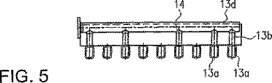
図1、図5、図6及び図7からわかるように、図5は図6の線I−Iに沿って切った断面であるが、ここではフィルタキャンドルは第1導管13aに通じており、この導管で支持されている。図7から特にわかるように、垂直に配置されたフィルタキャンドル10はフィルタ容器12の断面上で均等に分散されている。第1導管13aはフィルタキャンドル10に対して垂直な平面内で互いに平行に配置され、両側が閉じられている。中央に配置されている第1導管13aは端に近い第1導管13aよりも長くなっている。
As can be seen from FIGS. 1, 5, 6 and 7, FIG. 5 is a section taken along line I-I in FIG. 6, where the filter candle leads to the first conduit 13a, Supported by this conduit. As can be seen in particular from FIG. 7, the vertically arranged
フィルタキャンドル10は第1導管13aに適した開口部に通じており、第1導管13aで支持されている。第1導管13aの上方に少なくとも1つの追加導管が第1導管13aに対して所定の角度、好ましくは90度をなして延びており、第1導管13aと結合している。この実施形態では、排出手段3aと3bに接続された2つの第2導管13eと第2導管13dがかかる追加導管として備えられている。第2導管13eと第2導管13dにはその全長にわたって分散配置された接続点14が供されており、それらは中間導管13bを介して下側の第1導管13aに接続されている。このことは、上側の第2導管13dが中間導管13bを介して第1導管13aに接続され、上側の第2導管13eが中間導管13cを介して第1導管13aに接続されることを意味している。ただし、中間導管13bと中間導管13cがなくても、第2導管13eと第2導管13dを接続点14で直接接続することもできる。
この実施形態ではしたがって、図6及び図7に示された2つのグループAとBを形成するようにフィルタキャンドル10が排出管13a〜13eによって結合されるため、フィルタキャンドル10の濾液が個々の排出管13a〜13eを通って2つの排出手段3aと3bに供給される。その結果、個々の排出手段3a又は3bを通って、特定領域のフィルタキャンドルだけでなく、フィルタ容器の断面全体に均等に分散されているフィルタキャンドルに到達できる。これによって均一な洗浄効果が得られるため、逆フラッシングにとって特に好都合である。
In this embodiment, therefore, the
排出管13a〜13eは、支持部材15によって容器の壁に固定されている。この配置では、濾液が排出管13a〜13eを通って排出されるため、仕切り版を追加しないでも原液室を形成することができる。
The discharge pipes 13a to 13e are fixed to the wall of the container by the
濾過処理時、原液は供給手段2から原液室5に流れ込み、プリコート層を通過してフィルタキャンドル10に入る。この方法で生成された濾液は、次にフィルタキャンドル10から第1導管13aに流れ込む。各第1導管13aは接続点14で少なくとも2つの上側の第2導管13e又は13dのいずれかに接続されているため、第1導管13aからの濾液が接続点14を通って上側の第2導管13e又は13dに流れ込み、次に、個々の排出手段3aと3bに供給される。
During the filtration process, the stock solution flows from the supply means 2 into the
逆フラッシング時、排出手段3aと3bから洗浄液がフィルタキャンドルに供給される。この接続では、上記したようにグループAとBを分離することができるため、すなわち逆フラッシング時に一方のグループだけに洗浄液を供給することができるため、非常に高い流速と強い圧力で逆フラッシング処理を行うことができる。したがって、より効果的な洗浄が可能になり、洗浄液を節約することもできる。
During reverse flushing, cleaning liquid is supplied to the filter candle from the discharge means 3a and 3 b. In this connection, since the groups A and B can be separated as described above , that is, the cleaning liquid can be supplied to only one group at the time of reverse flushing, the reverse flushing process is performed with a very high flow rate and strong pressure. It can be carried out. Therefore, more effective cleaning is possible, and the cleaning liquid can be saved.
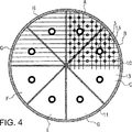
図2は、本発明のさらなる実施形態を示している。図1に示した第1実施形態と同様に、図2に示したビールフィルタも、原液供給手段2、前記原液供給手段2用の制御弁9、及び垂直に配置された複数のフィルタキャンドル10を備えるフィルタ容器12を包含する。フィルタキャンドル10はフィルタ容器12内で均等に分散されているが、この実施形態では多孔板11から吊り下げられている。図3と図4は、かかる多孔板の例を示している。図4からわかるように、フィルタキャンドル10が多孔板11の開口部に通じており、多孔板11は複数の室13に再分割されていて、ここでは排出管に相当する。この実施形態における多孔板は、たとえば8つのセグメントに再分割され、各部分にそれぞれ排出手段3が設けられている(図2では、2つの排出手段(3)を示している)。その結果、それぞれの排出管、この例では、多孔板上に形成された室13によってフィルタキャンドル10は8つのグループA〜Hを形成するように結合され、フィルタキャンドル10の濾液はそれぞれの室13を通って該当する排出手段3に供給することができる。排出手段3は外部において再結合が可能である。
FIG. 2 shows a further embodiment of the invention. As in the first embodiment shown in FIG. 1, the beer filter shown in FIG. 2 also includes a stock solution supply means 2, a control valve 9 for the stock solution supply means 2, and a plurality of
濾過処理時、原液が供給手段2から原液室5に流れ込み、プリコート層を通過してフィルタキャンドル10に入る。次に、濾液が多孔板11から室13に流れ込み、該当する排出手段3に供給される。フィルタキャンドルへの原液流を向上するために、原液流用の排出手段4を供することもでき、前記排出手段4は多孔板11を基準にしてフィルタキャンドルの上端に配置される。多孔板に原液用の追加した開口部がある場合、原液流は多孔板を通ってフィルタ容器12の上端に流れることができるので、一部の原液用の排出手段4を多孔板の上方に配置することもできる。原液流は図示されていないバイパス管を経由して、たとえば供給手段2から原液室5に再び供給することができる。
During the filtration process, the stock solution flows from the supply means 2 into the
図1に示した実施形態と同様、この実施形態でも分離された濾液室は設けられていない。図1に関して説明した逆フラッシングに対する利点が、この実施形態にも当てはまる。すなわち、逆フラッシング時に個別の上記グループA〜Hを互いに分離できるため、より高い流速と強い圧力でフィルタキャンドルを個別に逆フラッシングすることができる。この配置の利点は、従来の仕切り板を本発明に従う複数の排出手段3を備える多孔板に取り替えるだけで、本発明を既存のシステムに組み込めるということに見ることができる。
Similar to the embodiment shown in FIG. 1, this embodiment does not have a separate filtrate chamber. The advantages over reverse flushing described with respect to FIG. 1 also apply to this embodiment. That is, since it is possible to separate from one another individual of the group A~H during reverse flushing, it is possible to reverse flushing individually filter candle at a higher velocity and strong pressure. The advantage of this arrangement can be seen that the present invention can be incorporated into existing systems simply by replacing the conventional partition plate with a perforated plate comprising a plurality of discharge means 3 according to the present invention.
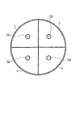
図3は、本発明によるビールフィルタ用多孔板の新たな実施形態の平面図をさらに示している。この実施形態では、多孔板が4つの部分、すなわち4つの排出手段33a、33b、33c、33dに分割されている。多孔板は、容器の大きさに応じて4、6、又は8つの部分に分割できる。
FIG. 3 further shows a plan view of a new embodiment of a perforated plate for beer filters according to the present invention. In this embodiment, the perforated plate is divided into four parts, that is, four discharging
図10は、もう一つの可能な実施形態を示しており、図2に示した実施形態と同様にフィルタキャンドル10が多孔板11に通じている。十分に安定した多孔板であれば、それ自体がカバーの役割を果たすことができる。フィルタキャンドル10が多孔板11の開口部によって排出管13aに接続され、図5及び図6に示した配置と同様に、前記排出管(13a)がフィルタキャンドル10に対して垂直な面に互いに平行に配置され、両側が閉じられている。次に、たとえば中間導管13bを介して導管13aを少なくとも1つの追加導管、この実施形態では、導管13aに対して所定の角度(好ましくは90度)をなして延びている2つの導管13eと13d、に接続することができる。2つのグループAとBを形成するようにフィルタキャンドルが導管13aと13bによって組み合わされ、個々の排出手段3(図示なし)に案内される。
FIG. 10 shows another possible embodiment, in which the
図10において、導管13aの最下流列に代わって集水軸13を多孔板11に溶接し、前記集水軸に適切な追加導管を備えることもできる。
In FIG. 10, the
本発明によるビールフィルタでは、従来の技術のように頭部室という形で濾液室を供することは無く、フィルタキャンドルのいくつかのグループがそれぞれの排出管を備え、一つの上に次を重ねて階層配置にすることができる。図8からわかるように、フィルタ容器12は、互いに並行かつ垂直に配置された第1のフィルタキャンドル10Iを備え、それぞれの排出管13Iが供されており、同様に互いに並行かつ垂直に配置された第2のフィルタキャンドル10IIが配置され、それぞれの排出管13IIが供されている。排出管13Iと13IIの構造設計は、たとえば図5、図6及び図7の第1実施形態に関して説明したものに対応する。図5、図6、及び図7に示した導管を使用すれば、原液が容易に排出管13を通過して、前記排出管の上方に配置された第1のフィルタキャンドル10Iに達することができる。
In the beer filter according to the present invention, the filtrate chamber is not provided in the form of a head chamber as in the prior art, and several groups of filter candles are provided with respective discharge pipes, one on top of the other. It can be arranged in a hierarchy. As can be seen from FIG. 8, the
目的にかなう原液流を維持するために、フィルタ容器12の上端に原液が排出される原液用の排出手段4を設ければ好都合であろうし、さらに必要であれば、バイパス管(図示していない)を経由して、たとえば供給手段2から原液室5の下端に再び供給される。
In order to maintain the stock solution flow for the purpose, it would be convenient to provide a stock solution discharge means 4 for discharging the stock solution at the upper end of the
Claims (2)
前記フィルタキャンドル(10)からの濾液がそれぞれの排出管を通って少なくとも2つの排出手段(3a、3b)に供給されるように前記フィルタキャンドルが前記排出管によって結合されており、
前記排出管は、複数の第1導管(13a)と、複数の中間導管(13b、13c)と、少なくとも2つの第2導管(13d、13e)とを含んでおり、
前記第1導管(13a)は、前記フィルタキャンドル(10)に対して垂直な面に互いに平行に配置され、かつその両側が閉じられており、
前記少なくとも2つの第2導管(13d、13e)は、前記第1導管の上方に配置されており、
前記中間導管(13b、13c)のそれぞれは、前記第1導管と前記第2導管との間に配置されており、
前記フィルタキャンドルは、前記第1導管に通じており、
前記第1導管のそれぞれは、前記中間導管のいずれかに所定の角度で接続されており、該中間導管は、前記少なくとも2つの第2導管のいずれかに所定の角度で接続されており、
前記少なくとも2つの第2導管のそれぞれは、前記少なくとも2つの排出手段(3a、3b)のいずれかに接続されており、
前記少なくとも2つの第2導管のそれぞれには、複数の接続部(14)が設けられており、
前記複数の接続部(14)は、前記第2導管の全長にわたり分散配置され、
前記複数の接続部(14)は、前記第2導管を前記中間導管と連通させている、ビールフィルタ。In a beer filter having a filter container (12) comprising a stock solution supply means (2) and a stock solution chamber (5) in which a plurality of filter candles (10) are arranged,
Wherein and filtrate from the filter candles (10) is coupled the filter candles by the discharge pipe to be supplied to at least two discharge means through each of the discharge pipe (3a, 3b),
The discharge pipe includes a plurality of first conduits (13a), a plurality of intermediate conduits (13b, 13c), and at least two second conduits (13d, 13e);
The first conduit (13a) is arranged parallel to each other in a plane perpendicular to the filter candle (10), and both sides thereof are closed,
The at least two second conduits (13d, 13e) are disposed above the first conduit;
Each of the intermediate conduits (13b, 13c) is disposed between the first conduit and the second conduit;
The filter candle leads to the first conduit;
Wherein each of the first conduit, said being connected at a predetermined angle to one of the intermediate conduit, the intermediate conduit is connected at a predetermined angle to one of said at least two second conduit,
Each of the at least two second conduits is connected to one of the at least two discharge means (3a, 3b);
Each of the at least two second conduits is provided with a plurality of connections (14);
Wherein the plurality of connecting portions (14) are distributed over the entire length of the second conduit,
The plurality of connecting portions (14) is configured to communicate the second conduit with the intermediate conduit.
前記複数のユニットは、前記フィルタ容器(12)内で一つの該ユニットの上に別の該ユニットを重ねるように階層配置されている、請求項1に記載のビールフィルタ。The beer filter according to claim 1, comprising a plurality of units including the discharge pipe and the plurality of filter candles (10).
2. The beer filter according to claim 1, wherein the plurality of units are arranged in a hierarchy so as to overlap another unit on one unit in the filter container (12).
Applications Claiming Priority (2)
| Application Number | Priority Date | Filing Date | Title |
|---|---|---|---|
| EP01107077A EP1243300B1 (en) | 2001-03-21 | 2001-03-21 | Filter candle device for beer filtration |
| PCT/EP2002/002975 WO2002074411A1 (en) | 2001-03-21 | 2002-03-18 | Beer filter |
Publications (3)
| Publication Number | Publication Date |
|---|---|
| JP2004525633A JP2004525633A (en) | 2004-08-26 |
| JP2004525633A5 JP2004525633A5 (en) | 2005-07-21 |
| JP3987801B2 true JP3987801B2 (en) | 2007-10-10 |
Family
ID=8176876
Family Applications (1)
| Application Number | Title | Priority Date | Filing Date |
|---|---|---|---|
| JP2002573117A Expired - Fee Related JP3987801B2 (en) | 2001-03-21 | 2002-03-18 | Beer filter |
Country Status (6)
| Country | Link |
|---|---|
| EP (1) | EP1243300B1 (en) |
| JP (1) | JP3987801B2 (en) |
| AT (1) | ATE268203T1 (en) |
| CZ (1) | CZ295288B6 (en) |
| DE (1) | DE50102465D1 (en) |
| WO (1) | WO2002074411A1 (en) |
Families Citing this family (7)
| Publication number | Priority date | Publication date | Assignee | Title |
|---|---|---|---|---|
| DE10340366B4 (en) * | 2003-09-02 | 2008-12-18 | Khs Ag | filter means |
| DE102013216134A1 (en) | 2013-08-14 | 2015-02-19 | Krones Ag | Precoat candle filter and filter cartridge with inner body |
| DE102014226428A1 (en) | 2014-12-18 | 2016-06-23 | Krones Ag | Apparatus and method for precoat filtration |
| DE102014226431A1 (en) | 2014-12-18 | 2016-06-23 | Krones Ag | Hydrodynamically optimized filter cartridge |
| EP3165596B1 (en) | 2015-11-05 | 2019-07-24 | Simon H. Steiner, Hopfen, GmbH | Method for purifying beer and beer purifier |
| DE102017200583A1 (en) | 2016-06-20 | 2017-12-21 | Krones Aktiengesellschaft | Precoat filtration with a filter aid |
| DE102016113440A1 (en) * | 2016-07-21 | 2018-01-25 | Putsch Gmbh & Co. Kg | filter |
Family Cites Families (5)
| Publication number | Priority date | Publication date | Assignee | Title |
|---|---|---|---|---|
| US2954873A (en) * | 1956-02-13 | 1960-10-04 | Ward Ind Corp | Block-off plate for back wash operation |
| CH657066A5 (en) * | 1981-05-12 | 1986-08-15 | Mueller Drm Ag | METHOD FOR CONTINUOUSLY THICKNING SUSPENSIONS. |
| NO155124C (en) * | 1981-07-16 | 1987-02-18 | Mueller Drm Ag | REWASHABLE EXPOSURE FILTER. |
| US5152815A (en) * | 1989-09-05 | 1992-10-06 | Zievers James F | Type 114 tiered filter |
| DE4209519C3 (en) * | 1992-03-24 | 2000-06-15 | Pall Corp | Method and device for quickly testing the integrity of filter elements |
-
2001
- 2001-03-21 DE DE50102465T patent/DE50102465D1/en not_active Expired - Lifetime
- 2001-03-21 EP EP01107077A patent/EP1243300B1/en not_active Expired - Lifetime
- 2001-03-21 AT AT01107077T patent/ATE268203T1/en not_active IP Right Cessation
-
2002
- 2002-03-18 JP JP2002573117A patent/JP3987801B2/en not_active Expired - Fee Related
- 2002-03-18 CZ CZ20032772A patent/CZ295288B6/en not_active IP Right Cessation
- 2002-03-18 WO PCT/EP2002/002975 patent/WO2002074411A1/en active IP Right Grant
Also Published As
| Publication number | Publication date |
|---|---|
| CZ20032772A3 (en) | 2004-04-14 |
| CZ295288B6 (en) | 2005-06-15 |
| JP2004525633A (en) | 2004-08-26 |
| WO2002074411A1 (en) | 2002-09-26 |
| ATE268203T1 (en) | 2004-06-15 |
| EP1243300A1 (en) | 2002-09-25 |
| DE50102465D1 (en) | 2004-07-08 |
| EP1243300B1 (en) | 2004-06-02 |
Similar Documents
| Publication | Publication Date | Title |
|---|---|---|
| CN101039739B (en) | Methods and apparatus for removing solids from a membrane module | |
| EP1830941B1 (en) | Cross flow filter device with concentric filter elements | |
| FI71068C (en) | MOTSKOELJBART LJUSSKOELJNINGSFILTER | |
| US4643827A (en) | Filter press for cake filtration | |
| EA036835B1 (en) | Method of water filtration | |
| CN111135718B (en) | Sewage filtering device and filtering method | |
| US8070946B2 (en) | Underdrain for a filter system for filtering water or wastewater and a method of washing the filter system | |
| JP3987801B2 (en) | Beer filter | |
| US5972228A (en) | Filters employing "filling bodies" to reduce the amount of backwashing fluid remaining in the filters after backwashing | |
| KR200156598Y1 (en) | Underdrain system for rapid filtration | |
| JPH078719A (en) | Filter | |
| RU2255790C2 (en) | Method of separation of suspensions and press filter for realization of this method | |
| JP4299396B2 (en) | Air-water distribution device and water treatment device using the air-water distribution device | |
| KR101685356B1 (en) | Vertical Type Hollow Fiber Membrane Module and Filtering System Using The Same | |
| CN215516749U (en) | Ceramic fine filtering device | |
| US5792359A (en) | Sealing shoe for celless travelling bridge filter | |
| JPH08332354A (en) | Solid-liquid separator and cleaning method thereof | |
| US2754971A (en) | Multicell filter apparatus | |
| JPH07108144A (en) | Clarifying filter | |
| RU2003115476A (en) | METHOD FOR SUSPENSION SEPARATION AND FILTER PRESS FOR ITS IMPLEMENTATION | |
| JPS6297608A (en) | Hollow yarn membrane filter | |
| JPH09253416A (en) | Apparatus for purifying bath water | |
| CN117440935A (en) | Oil removing device and flushing method thereof | |
| KR200395995Y1 (en) | Proper move system of back flushing method that use siphon basic | |
| JPH08332353A (en) | Solid-liquid separator |
Legal Events
| Date | Code | Title | Description |
|---|---|---|---|
| A977 | Report on retrieval |
Free format text: JAPANESE INTERMEDIATE CODE: A971007 Effective date: 20060622 |
|
| A131 | Notification of reasons for refusal |
Free format text: JAPANESE INTERMEDIATE CODE: A131 Effective date: 20060627 |
|
| A521 | Request for written amendment filed |
Free format text: JAPANESE INTERMEDIATE CODE: A523 Effective date: 20060927 |
|
| A131 | Notification of reasons for refusal |
Free format text: JAPANESE INTERMEDIATE CODE: A131 Effective date: 20061114 |
|
| A601 | Written request for extension of time |
Free format text: JAPANESE INTERMEDIATE CODE: A601 Effective date: 20070214 |
|
| A602 | Written permission of extension of time |
Free format text: JAPANESE INTERMEDIATE CODE: A602 Effective date: 20070221 |
|
| A521 | Request for written amendment filed |
Free format text: JAPANESE INTERMEDIATE CODE: A523 Effective date: 20070514 |
|
| TRDD | Decision of grant or rejection written | ||
| A01 | Written decision to grant a patent or to grant a registration (utility model) |
Free format text: JAPANESE INTERMEDIATE CODE: A01 Effective date: 20070619 |
|
| A61 | First payment of annual fees (during grant procedure) |
Free format text: JAPANESE INTERMEDIATE CODE: A61 Effective date: 20070713 |
|
| R150 | Certificate of patent or registration of utility model |
Ref document number: 3987801 Country of ref document: JP Free format text: JAPANESE INTERMEDIATE CODE: R150 Free format text: JAPANESE INTERMEDIATE CODE: R150 |
|
| FPAY | Renewal fee payment (event date is renewal date of database) |
Free format text: PAYMENT UNTIL: 20100720 Year of fee payment: 3 |
|
| FPAY | Renewal fee payment (event date is renewal date of database) |
Free format text: PAYMENT UNTIL: 20110720 Year of fee payment: 4 |
|
| R250 | Receipt of annual fees |
Free format text: JAPANESE INTERMEDIATE CODE: R250 |
|
| FPAY | Renewal fee payment (event date is renewal date of database) |
Free format text: PAYMENT UNTIL: 20110720 Year of fee payment: 4 |
|
| FPAY | Renewal fee payment (event date is renewal date of database) |
Free format text: PAYMENT UNTIL: 20120720 Year of fee payment: 5 |
|
| R250 | Receipt of annual fees |
Free format text: JAPANESE INTERMEDIATE CODE: R250 |
|
| FPAY | Renewal fee payment (event date is renewal date of database) |
Free format text: PAYMENT UNTIL: 20120720 Year of fee payment: 5 |
|
| FPAY | Renewal fee payment (event date is renewal date of database) |
Free format text: PAYMENT UNTIL: 20130720 Year of fee payment: 6 |
|
| R250 | Receipt of annual fees |
Free format text: JAPANESE INTERMEDIATE CODE: R250 |
|
| R250 | Receipt of annual fees |
Free format text: JAPANESE INTERMEDIATE CODE: R250 |
|
| R250 | Receipt of annual fees |
Free format text: JAPANESE INTERMEDIATE CODE: R250 |
|
| R250 | Receipt of annual fees |
Free format text: JAPANESE INTERMEDIATE CODE: R250 |
|
| R250 | Receipt of annual fees |
Free format text: JAPANESE INTERMEDIATE CODE: R250 |
|
| R250 | Receipt of annual fees |
Free format text: JAPANESE INTERMEDIATE CODE: R250 |
|
| R250 | Receipt of annual fees |
Free format text: JAPANESE INTERMEDIATE CODE: R250 |
|
| LAPS | Cancellation because of no payment of annual fees |