JP3986650B2 - Fire extinguishing equipment for parking lots - Google Patents
Fire extinguishing equipment for parking lots Download PDFInfo
- Publication number
- JP3986650B2 JP3986650B2 JP04087498A JP4087498A JP3986650B2 JP 3986650 B2 JP3986650 B2 JP 3986650B2 JP 04087498 A JP04087498 A JP 04087498A JP 4087498 A JP4087498 A JP 4087498A JP 3986650 B2 JP3986650 B2 JP 3986650B2
- Authority
- JP
- Japan
- Prior art keywords
- fire extinguishing
- water
- pressure
- fire
- foam
- Prior art date
- Legal status (The legal status is an assumption and is not a legal conclusion. Google has not performed a legal analysis and makes no representation as to the accuracy of the status listed.)
- Expired - Fee Related
Links
Images

Classifications
-
- A—HUMAN NECESSITIES
- A62—LIFE-SAVING; FIRE-FIGHTING
- A62C—FIRE-FIGHTING
- A62C3/00—Fire prevention, containment or extinguishing specially adapted for particular objects or places
- A62C3/07—Fire prevention, containment or extinguishing specially adapted for particular objects or places in vehicles, e.g. in road vehicles
Description
【0001】
【発明の属する技術分野】
本発明は駐車場の消火設備に関するもので、特にA火災(普通火災)にもB火災(油火災)にも適した消火設備である。
【0002】
【従来の技術】
一般的に油火災には水を使用できず、泡による窒息消火が期待される。このため駐車場には、ガソリン火災に備えて、開放型の消火ヘッドを有する泡消火設備が設けられている。
【0003】
この泡消火設備に閉鎖型の消火ヘッドが使用されない理由の一つは、消火ヘッドから泡が放出されるためである。つまり泡は軽量であるため、水に対して消火ヘッドから飛散される距離が短く、一つの消火ヘッドの防護範囲が小さい。この点を解決するため、泡消火設備では、複数の開放型ヘッドからの一斉放出方式をとることで、泡を均一に散布することの難しさ、またガソリン等の油の流出による火災の拡大に対処できるようにしている。
【0004】
【発明が解決しようとする課題】
しかし駐車場における火災事例を実際に調査してみると、ガソリンが燃えた事例はほとんどなく、エンジンの加熱、車内での発火、ケーブルの加熱といったA火災に相当する可燃物の火災が意外と多い。つまり上記のような一斉放出方式をとる必要はなく、単一の消火ヘッドによる局所的な放出でほとんどの火災が消火可能である。
【0005】
また泡消火設備は、主にB火災の抑制と消火を主眼においた設備であるため、A火災に対しては、通常のスプリンクラ消火設備と比較すると、冷却、延焼防止において性能が劣るものと考えられる。
【0006】
そこで、本発明は以上のような事情に鑑み、駐車場における有効な消火設備を得ることを目的とする。
【0007】
【課題を解決するための手段】
本発明は、給水源及び水成膜泡消火薬剤源に接続され、該給水源から供給される消火用水と該水成膜泡消火薬剤源から供給される水成膜泡消火薬剤とを混合して低発泡性である泡水溶液を生成する混合器と、該混合器の二次側に配管を介して接続される閉鎖型の消火ヘッドと、該消火ヘッドと前記混合器の間に設けられる圧力調整機能付きの流水検知装置とを備え、配管内の泡水溶液の圧力が、数個の消火ヘッドが動作しても確実に放水できるように設定された消火設備であって、流水検知装置は、シリンダ室を有する流水検知弁本体と、該流水検知弁本体の給水源側に連通する一次側と、消火ヘッドに連通する二次側とを連結し、かつシリンダ室に連結されるバイパス経路と、該バイパス経路の下流側に設けられる調圧パイロット弁と、該調圧パイロット弁と前記二次側との間に設けられる安全弁と、シリンダ室に挿着されたピストンの中央部に立設されるロッドと、シリンダ室の頭部に設けられ、シリンダ室が減圧して弁体がリフトすると、ロッドにより作動されて、流水検知信号を消火制御盤に出力するリミットスイッチとから構成され、消火ヘッドは、防護範囲を拡大できるように周縁部に爪を有しないデフレクタを有し、火災の際、泡水溶液を、該デフレクタから、炎に対して貫通力を有すると共に消火範囲を拡大するように、ほぼ水溶液の状態のまま泡立つことなく、小さな水滴状にして放出し、圧力調整機能付きの流水検知装置により、消火ヘッドが1個又は複数個動作するどちらの場合でも、最適な圧力で泡水溶液を放出できるものであり、調圧パイロット弁は、消火ヘッドに連通する二次側の圧力が上昇し、監視圧を越えると、調圧パイロット弁での流量とシリンダ室の減圧度合と流水検知弁本体の弁体との開放度合との関係が平衡状態となり、消火ヘッドに放水に必要な泡水溶液を適正な圧力で供給することを特徴とするものである。
【0008】
【発明の実施の形態】
実施形態1
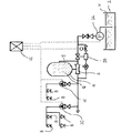
この発明の実施例を図1により説明する。2は消火用水Wが貯えられた給水源としての水槽、4は水成膜泡消火薬剤Gを収容した薬剤タンクである。6は混合器で、水槽2と薬剤タンク4に接続され、水槽2から供給される消火用水Wと薬剤タンク4から供給される水成膜泡消火薬剤Gとを混合して水成膜溶液としての泡水溶液を生成する。
【0009】
なお水槽2から消火用水Wが混合器6に供給される際、その消火用水Wの一部は配管5を通って薬剤タンク4にも供給される。薬剤タンク4では消火用水Wが供給されることによって、混合器6に水成膜泡消火薬剤Gを供給することになる。
【0010】
この水成膜泡消火薬剤Gは、フッ素系界面活性剤を主成分とし、起泡安定剤、水溶性高分子、凍結抑止剤等からなる水溶性液体用の泡消火薬剤である。一般的には、泡と水成膜の両者の空気遮断作用により消火を行う。しかし本発明では、消火ヘッドから泡水溶液をほとんど泡立っていない状態で噴霧し、可燃物や燃料の表面に薄膜、所謂水成膜を形成して被覆し、窒息消火させるものである。
【0011】
8は混合器6の二次側に配管を介して接続された閉鎖型消火ヘッドで、普通火災(A火災)と油火災(B火災)の両方の火災発生の可能性がある防護区域としての駐車場に設置される。勿論、消火ヘッド8をA火災やB火災が単独で発生する防護区域に設けても構わない。
【0012】
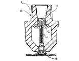
この閉鎖型消火ヘッド8を図2を用いて説明する。閉鎖型消火ヘッド8は、ヘッド本体10と、放出口11を閉鎖する弁体12と、弁体12を放出口11に押し付ける感熱部材の一例としてのグラスバルブ13と、放出口11から放出される泡水溶液をほぼ水溶液の状態のまま防護区域に分散するデフレクタ14とを備えている。なおグラスバルブ13は全体が細い速動型のものを使用するのが好ましい。またデフレクタ14には、外周に爪を有しないものを使用することが好ましい。これは、防護範囲を拡大できるためである。
【0013】
ところで泡消火設備で従来、使用される泡ヘッドは、デフレクタを金網によって覆うことで、放出口から放出される泡水溶液の発泡倍率を高めている。この発泡倍率は低膨張の場合で数倍以上で、高膨張の場合は数百倍に達するようにしてある。これに対して本発明の閉鎖型消火ヘッド8は、金網を除去し、デフレクタ14を外部に露出させた構造にしている。これにより、放出口11から放水された泡水溶液(混合液)はほとんど発泡することなく、全周方向に拡散放出され、拡散時に泡水溶液が泡立つのを抑えることが可能となる。
【0014】
20は防護区画毎に設けられた流水検知装置で、閉鎖型消火ヘッド8と混合器6の間に設けられる。流水検知装置20の二次側配管内は泡水溶液又は水が満たされており、閉鎖型消火ヘッド8が開放して二次側配管内の圧力が低下すると、流水検知装置20は消火制御盤22に圧力低下に基づく流水検知信号を出力する。
【0015】
なお図1において、24はポンプ、26はポンプ24から圧送される消火用水Wの水圧を調整して混合器6に送出する圧力調整弁で、それぞれ消火制御盤22と信号線を介して接続される。また図示はしないが、ポンプ24と混合器6の間に、二次側配管内を所定の圧力に加圧するための圧縮空気が貯留された圧力空気槽を接続して、この圧力空気槽内の圧縮空気が所定値よりも低下した時に、ポンプ24を起動させるようにしてもよい。
【0016】
次にこの実施形態の作動について説明する。駐車場で例えば、車両等の燃料が原因となるB火災が発生すると、その熱によって閉鎖型消火ヘッド8のグラスバルブ13内のアルコールが膨張し、その結果、グラスバルブ13は破裂する。これにより弁体12が落下し放出口11が開放され、流水検知装置20の二次側配管内に溜まっていた泡水溶液が放出口11から放出される。そして流水検知装置20は消火制御盤22に流水検知信号を出力し、それにより消火制御盤22からポンプ24にポンプ起動信号が送信され、ポンプ24が起動される。
【0017】
このポンプ24の起動に伴い、圧力調整弁26により圧力を調整されながら、水槽2の消火用水Wが混合器6及び薬剤タンク4に供給される。混合器6は水槽2から供給された消火用水Wと薬剤タンク4から供給された水成膜泡消火薬剤Gとを混合して、所定濃度、例えば1.0%〜3.0%、好ましくは2.0%〜3.0%の泡水溶液を生成する。この泡水溶液は流水検知装置20及び二次側配管を通って、閉鎖型消火ヘッド8に供給され、放出口11からデフレクタ14に向かって放出される。
【0018】
この時、閉鎖型消火ヘッド8には、金網がなくデフレクタ14が外部に露出した状態で取り付けられており、また泡水溶液自体も低発泡性であるため、泡水溶液はほとんど泡立つことなく、ほぼ液体の状態で直接、消火ヘッド8から放出される。
【0019】
つまりデフレクタ14によって泡水溶液を小さな水滴状にして飛散させるため、速度エネルギーが減少せず、よって泡状で放出される場合に比べて大幅にその飛距離を伸ばすことができるので消火範囲を拡大することが可能となり、また炎に対して高い貫通力を有する。
【0020】
また泡水溶液は火炎の中に直接飛び込み、炎の気流に逆らって燃料の表面に達して、その燃料の表面に水成膜を形成する。この水成膜は拡散されて燃料全体を覆い窒息消火させる。この水成膜の広がり方は非常に迅速で、燃料表面の隅々にまで及ぶので、効果的な消火を行うことができる。
【0021】
次に防護区域にある例えばダンボールなどが燃えてA火災が発生した場合について説明する。上述したように、閉鎖型消火ヘッド8からは泡水溶液は泡ではなく、ほぼ液体の状態で放出される。このため燃焼物に泡水溶液が降りかかると、燃焼物は泡水溶液によって冷却されるという所謂冷却効果によって消火される。このように本発明では、泡水溶液を直接ほぼ液体のまま放出することで、A火災に対して、通常のスプリンクラ消火設備における消火と同様な消火効果を得ることが可能となる。
【0022】
本発明は以上のように構成されるので、実際上はA火災の発生が多い駐車場に泡消火設備を設置する場合に比べ、冷却効果が増し、消火効率が向上する。また消火ヘッド8を閉鎖型で構成しても、放出される泡水溶液を泡ではなく、小さな水滴状にして飛散させるため、飛距離が向上し消火範囲を向上させることが可能となる。つまり開放型ヘッドによる一斉放出方式を備えなくても、十分に単一のヘッドからの放水で消火可能であるので、設備を簡易なものにできる。しかも仮にB火災が発生しても、水成膜による窒息消火により火災を確実に消火できる。即ち本発明は、A火災及びB火災の両方に適した消火設備であると言える。
【0023】
実施形態2
実施形態1のように消火ヘッド8を閉鎖型で構成すると、動作するヘッドの個数は火災によって変化するので、数個のヘッドが動作しても確実に放水できるように予め二次側配管の圧力を設定しておく必要がある。しかしそのようにした場合に、消火ヘッド8が1個しか動作しないと、消火ヘッド8から泡水溶液が高圧で放出されることになり、その結果、泡水溶液の粒子が非常に小さくなって炎に対する貫通力がなくなってしまう。そこで実施形態2では、圧力調整手段を設けることで、消火ヘッド8が1個または数個動作するどちらの場合でも、最適な圧力で泡水溶液を放出できるようにする。
【0024】
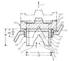
図3は図1の流水検知装置20の一例を示した断面図で、流水検知装置20は流水検知弁本体、調圧パイロット弁55及び安全弁63によって構成される。以下、この図面を用いて本実施形態2を説明する。
【0025】
本体31には、連通口32が設けられる。この連通口32は、ポンプ24に連通する一次側33と、消火ヘッド8に連通する二次側35とを連通させる。連通口32には、弁座36が装着されている。この弁座36は、弁座部37と内径L2の脚部38とから構成されている。
【0026】
弁座36には弁体40が着座している。この弁体40の背面外周には円筒状のピストン41が形成され、その中央部には、リミットスイッチ42を作動せしめるロッド43が立設されている。このピストン41は、シリンダ室45に挿着されている。
【0027】
シリンダ室45の頭部46には、貫通穴47とリミットスイッチ42が設けられている。この貫通穴47には、シール手段48を介してロッド43が貫入されている。リミットスイッチ42は、このロッド43の移動軌跡内に設けられ、またリミットスイッチ42には防護カバー49が設けられる。シリンダ室45の頭部46と弁体40の背面との間には、閉弁方向に付勢するばね50が張設されている。なお弁体40の着座部40aはゴム等のシール部材により形成される。
【0028】
シリンダ室45は、一次側33と二次側35とを連結するバイパス経路52に連結される。シリンダ室45の上流側のバイパス経路52にはオリフィス51が設けられ、またその下流側には調圧パイロット弁55が設けられる。
【0029】
調圧パイロット弁55は、弁座58に離接する弁部59と、弁部59に連結されたダイヤフラム60と、ダイヤフラム60を開弁方向に付勢するばね61とを備えている。調圧パイロット弁55と二次側35との間には、安全弁63が設けられる。この安全弁63は、弁座65に離接する弁部64と、弁部64を閉弁方向に付勢するばね62とを備えている。
【0030】
弁体40の着座部40aの内周側には、高さH、直径L1のスカート部66が固定されている。このスカート66は、底面部67とスカート部68とから構成され、この底面部67は弁体40に螺着されている。
【0031】
スカート部68の上部には、円筒状の不開口領域70が設けられる。この領域70の高さH1は弁座36の脚部38の高さH2より短いが、両者の高さH1、H2は必要に応じて適宜選択される。
【0032】
この不開口領域70と脚部38との間には、ラビリンス隙間tが形成されるが、この隙間tの大きさは、流水検知装置20に必要な最低の流量に基づいて狭いことが望ましく、調圧機能を十分に発揮するためにも隙間tを通過する時の流量は少ないが方がよい。従って、設計精度に鑑み、弁座36の脚部38の高さH2は、ラビリンス効果によるシールが発生する程度の高さが選ばれる。
【0033】
スカート部68の不開口領域70の下部には、開口領域71が設けられる。この開口領域71は、小開口72と、小開口72と連続する大開口73とからなる。小開口72、大開口73が、半楕円状に形成されるが、その大きさや形状等は必要に応じて適宜選択される。
【0034】
次に本実施形態の作動について説明する。通常時、消火ヘッド8からの流水がない場合には、弁体40はシリンダ室45が一次側33により加圧され、完全に閉止している。この時、バイパス経路52の調圧パイロット弁55の作用により、二次側35の圧力が監視圧、例えば、6kg/cm2で常時加圧されている。これは、調圧パイロット弁55の弁部59がダイヤフラム60を介してばね61により二次側35の圧力が6kg/cm2で弁座58に着座するようになっているためである。
【0035】
二次側35に微量の水漏れがある場合、二次側35の圧力が低下するため、調圧パイロット弁55が少し開いて二次側35に少し泡水溶液が補充される。この時には、シリンダ室45はほとんど減圧しないので、弁体40は動かない。即ち、閉弁状態を維持する。
【0036】
二次側35で消火ヘッド8が作動し、一定以上の流水があると、二次側35の圧力が上記の場合よりも大きく低下して調圧パイロット弁55が大きく開いて二次側35に一次側33の泡水溶液を補充する。この時、バイパス経路52にオリフィス51が設けられているため、バイパス経路52を介して一次側33から二次側35への泡水溶液Fの供給が間に合わなくなる。そのため、シリンダ室45が減圧して弁体40がリフトし始める。
【0037】
弁体40がリフトし始めると、スカート66のスカート部68が上昇し始めるが、このスカート部68と弁座36の脚部38との間に、ラビリンス隙間tがあるので、この隙間tを通過する流量は充分抑えられたものとなる。そのため、二次側35の圧力減に対応し、不開口領域70の高さH1の分だけ弁体40は確実にリフトする。この弁体40のリフト分でロッド43がリミットスイッチ42を作動させるので確実に流水検知信号を出力できる。
【0038】
スカート部68が高さH1上昇し、図4の一点鎖線で示すように、小開口72が弁座36の上方に移動すると、泡水溶液Fwは小開口72を介して二次側35に流入する。二次側35の圧力が調圧パイロット弁55の監視圧より下回ると、調圧パイロット弁55は更に開いてシリンダ室45を更に減圧させる。そうすると、弁体40が一気にリフトし、二次側35の圧力を上昇させる。
【0039】
二次側35の圧力が上昇し、監視圧を越えると、調圧パイロット弁55の弁部59が開口度合いを狭める。そのため、シリンダ室45内の圧力もそれほど減圧されなくなり、この調圧パイロット弁55での流量とシリンダ室45の減圧度合と流水検知弁本体1の弁体40の開放度合との関係が平衡状態となる。その結果、消火ヘッド8には放水に必要な泡水溶液が適正な圧力で供給されることになり、消火効果のある放水が可能である。
【0040】
なお二次側35の配管には、樹脂管を使用しても不用意な高圧とならないように、安全弁63が設けられている。樹脂管はほぼ7kg/cm2の圧力が上限とされているが、安全を考慮して安全弁63からは6.5kg/cm2で排圧できるようになっている。
【0041】
【発明の効果】
以上のように本発明は、消火薬剤として水成膜泡消火薬剤を使用し、閉鎖型消火ヘッドから泡水溶液を泡状ではなく、ほぼ液体の状態で放出する。よって、普通火災に対しては燃焼物に泡水溶液を降りかけ冷却させることで火災を消火し、また油火災に対してはガソリン等の燃料の表面に水成膜を形成して、酸素を遮断することで火災を消火する。このため防護区域で普通火災及び油火災のいずれか発生しても、または両方が同時に発生しても、確実にその火災を消火することができる。このため実際上はA火災の発生が多い駐車場に有効な消火設備となる。
【0042】
また駐車場の火災はA火災が多く、開放型ヘッドによる一斉放出方式を備えてなくても、単一のヘッドからの放水で充分に消火可能であるという事情に鑑み、消火ヘッドを閉鎖型に構成することで、設備コストを安価にでき、防護区域への消火剤の放出を必要最小限にできるので、消火後の清掃等の処理が容易になる
この事は、水損減少につながる。
【0043】
しかも放出される泡水溶液を泡ではなく、小さな水滴状にして飛散させるため、飛距離が向上し消火範囲を大きくさせることが可能となり、仮にガソリン火災が発生しても、火災拡大に対して充分に対応できる。また流水検知装置に圧力調整機能を設けてあるので、二次側の圧力を最適な圧力に維持して放水を行うことが可能となる。この最適な圧力で放水するという事は、結果として消火性能や分布性能が向上するということにつながる。
【図面の簡単な説明】
【図1】本発明の消火設備のシステム図である。
【図2】閉鎖型消火ヘッドの断面図である。
【図3】圧力調整機能を付加した流水検知装置の一例を示す断面図である。
【図4】図3の弁体部分の拡大図である。
【符号の説明】
2 水槽、 4 薬剤タンク、 5 配管、 6 混合器、
8 閉鎖型消火ヘッド、 10 ヘッド本体、 11放出口、 12 弁体、
13 感熱部材、 14 デフレクタ、 20 流水検知装置、
22 消火制御盤、 24 ポンプ、 26 圧力調整弁、
31 本体、 32 連通口、 33 一次側、 35 二次側、
36 弁座、 37 弁座部、 38 脚部、 40 弁体、
40a 着座部、 41 ピストン、 42 リミットスイッチ、
43 ロッド、 45 シリンダ室、 46 頭部、47 貫通穴、
48 シール手段、 49 防護カバー、 51 オリフィス、
52 バイパス経路52、 55 調圧パイロット弁、 58 弁座、
59 弁部、 60 ダイヤフラム、 61 ばね、 62 ばね、
63 安全弁、 64 弁部、 65 弁座、 66 スカート部66、
67 底面部、 68 スカート部、 70 不開口領域、 71 開口領域、
72 小開口、 73 大開口、[0001]
BACKGROUND OF THE INVENTION
The present invention relates to a fire extinguishing facility for a parking lot, and is particularly suitable for both fire A (normal fire) and fire B (oil fire).
[0002]
[Prior art]
Generally, water cannot be used for oil fires, and suffocation with foam is expected. For this reason, the parking lot is provided with foam fire extinguishing equipment having an open fire extinguishing head in preparation for a gasoline fire.
[0003]
One reason why closed fire extinguishing heads are not used in the foam fire extinguishing equipment is that bubbles are discharged from the fire extinguishing heads. In other words, since the foam is lightweight, the distance from the fire extinguishing head to the water is short, and the protection range of one fire extinguishing head is small. To solve this problem, the foam fire extinguishing system uses a simultaneous release method from multiple open-type heads, which makes it difficult to spread foam evenly and expands the fire due to the spill of oil such as gasoline. I'm trying to deal with it.
[0004]
[Problems to be solved by the invention]
However, when we actually investigated fire cases in parking lots, there were almost no cases where gasoline burned, and there were surprisingly many fires of combustible materials corresponding to A fires such as engine heating, ignition in the car, and cable heating. That is, it is not necessary to take the simultaneous discharge method as described above, and most fires can be extinguished by local discharge by a single fire extinguishing head.
[0005]
In addition, the foam fire extinguishing equipment is mainly designed to suppress and extinguish the B fire. Therefore, the A fire is considered to be inferior in cooling and fire spread prevention compared to the normal sprinkler fire extinguishing equipment. It is done.
[0006]
In view of the above circumstances, an object of the present invention is to obtain an effective fire extinguishing facility in a parking lot.
[0007]
[Means for Solving the Problems]
The present invention is connected to a water supply source and a water film-forming foam fire extinguishing chemical source, and mixes water for fire extinguishing supplied from the water supply source and water film-forming foam fire-extinguishing chemical supplied from the water film-forming foam fire-extinguishing chemical source. A mixer for producing a foam aqueous solution having low foaming properties, a closed fire extinguishing head connected to the secondary side of the mixer via a pipe, and a pressure provided between the fire extinguishing head and the mixer A water flow detection device with an adjustment function, the pressure of the foam aqueous solution in the pipe is a fire extinguishing facility set so that water can be discharged reliably even if several fire extinguishing heads are operated. A flowing water detection valve body having a cylinder chamber, a primary side communicating with the water supply source side of the flowing water detection valve body, a secondary side communicating with the fire extinguishing head, and a bypass path connected to the cylinder chamber; A pressure regulating pilot valve provided downstream of the bypass path; A safety valve provided between the pressure pilot valve and the secondary side, a rod erected at the center of the piston inserted in the cylinder chamber, and a head of the cylinder chamber. When the valve body is lifted, it is composed of a limit switch that is actuated by a rod and outputs a running water detection signal to the fire extinguishing control panel, and the fire extinguishing head has a deflector that does not have a claw at the periphery so that the protection range can be expanded. In the event of a fire, the foam aqueous solution is released from the deflector in the form of small water droplets without foaming in the form of a substantially aqueous solution so as to have a penetration force against the flame and expand the fire extinguishing range, With either a single or multiple fire extinguishing heads operating with a water flow detection device with a pressure adjustment function, it is possible to release an aqueous foam solution at an optimal pressure. When the pressure on the secondary side communicating with the fire head rises and exceeds the monitoring pressure, the relationship between the flow rate at the pressure regulating pilot valve, the degree of pressure reduction in the cylinder chamber, and the degree of opening of the valve body of the flowing water detection valve body is balanced. In this state, the foam aqueous solution necessary for water discharge is supplied to the fire extinguishing head at an appropriate pressure.
[0008]
DETAILED DESCRIPTION OF THE INVENTION
Embodiment 1
An embodiment of the present invention will be described with reference to FIG. 2 is a water tank as a water supply source in which the water for fire extinguishing W is stored, and 4 is a chemical tank containing a water film forming foam fire extinguishing chemical G. Reference numeral 6 denotes a mixer, which is connected to the
[0009]
Note that when fire-extinguishing water W is supplied from the
[0010]
This water film-forming foam fire-extinguishing agent G is a foam-extinguishing agent for water-soluble liquids mainly composed of a fluorosurfactant and comprising a foaming stabilizer, a water-soluble polymer, a freeze inhibitor and the like. Generally, fire extinguishing is performed by the air blocking action of both foam and water film formation. However, in the present invention, the foam aqueous solution is sprayed from the fire extinguishing head in a state where there is almost no foam, and a thin film, so-called water film is formed on the surface of the combustible material or fuel to coat and extinguish the suffocation.
[0011]
8 is a closed-type fire extinguishing head connected to the secondary side of the mixer 6 via a pipe, as a protective area that may cause both a normal fire (A fire) and an oil fire (B fire). Installed in the parking lot. Of course, the
[0012]
The closed
[0013]
By the way, the foam head conventionally used with the foam fire extinguishing equipment has increased the foaming ratio of the foam aqueous solution discharged | emitted from a discharge port by covering a deflector with a metal net. The expansion ratio is several times or more in the case of low expansion, and reaches several hundred times in the case of high expansion. In contrast, the closed
[0014]
[0015]
In FIG. 1, 24 is a pump, and 26 is a pressure regulating valve that regulates the water pressure of the fire-extinguishing water W fed from the
[0016]
Next, the operation of this embodiment will be described. For example, when a B fire caused by fuel of a vehicle or the like occurs in the parking lot, alcohol in the
[0017]
With the activation of the
[0018]
At this time, the closed
[0019]
In other words, since the foam aqueous solution is scattered in the form of small water droplets by the
[0020]
Also, the aqueous foam solution directly jumps into the flame, reaches the surface of the fuel against the airflow of the flame, and forms a water film on the surface of the fuel. This water film is diffused to cover the entire fuel and extinguish the suffocation. The water film is spread very quickly and reaches every corner of the fuel surface, so that effective fire extinguishing can be performed.
[0021]
Next, description will be made on a case where A fire occurs due to, for example, cardboard in the protected area burning. As described above, the aqueous foam solution is discharged from the closed
[0022]
Since this invention is comprised as mentioned above, compared with the case where a foam fire extinguishing equipment is installed in a parking lot where generation | occurrence | production of A fire is large, a cooling effect increases and fire extinguishing efficiency improves. Even if the
[0023]
When the fire-extinguishing
[0024]
FIG. 3 is a cross-sectional view showing an example of the flowing
[0025]
The
[0026]
A
[0027]
A through hole 47 and a
[0028]
The
[0029]
The pressure regulating pilot valve 55 includes a
[0030]
A skirt portion 66 having a height H and a diameter L1 is fixed to the inner peripheral side of the
[0031]
A cylindrical
[0032]
A labyrinth gap t is formed between the
[0033]
An
[0034]
Next, the operation of this embodiment will be described. Normally, when there is no running water from the
[0035]
When there is a small amount of water leakage on the secondary side 35, the pressure on the secondary side 35 decreases, so the pressure regulating pilot valve 55 is opened a little to replenish the secondary side 35 with a little aqueous foam solution. At this time, since the
[0036]
When the
[0037]
When the
[0038]
When the
[0039]
When the pressure on the secondary side 35 rises and exceeds the monitoring pressure, the
[0040]
The secondary side 35 is provided with a safety valve 63 so that an unintentional high pressure does not occur even if a resin pipe is used. The upper limit of the pressure of the resin pipe is approximately 7 kg /
[0041]
【The invention's effect】
As described above, the present invention uses the water film foam extinguishing agent as the extinguishing agent, and discharges the aqueous foam solution from the closed fire extinguishing head in a substantially liquid state, not in the form of bubbles. Therefore, for normal fires, the fired product is extinguished by cooling with a foamed aqueous solution, and the fire is extinguished. For oil fires, a water film is formed on the surface of fuel such as gasoline to block oxygen To extinguish the fire. Therefore, even if either a normal fire or an oil fire occurs in the protected area, or both occur at the same time, the fire can be surely extinguished. Therefore, in practice, the fire extinguishing equipment is effective for parking lots where fires A frequently occur.
[0042]
In addition, there are many fires in parking lots A, and even if it does not have a simultaneous discharge system with an open head, it can be extinguished sufficiently with water discharged from a single head. By constructing, the equipment cost can be reduced and the release of the fire extinguishing agent to the protected area can be minimized. This facilitates the cleaning process after the fire extinguishing, leading to a reduction in water loss.
[0043]
In addition, since the aqueous foam solution is scattered in the form of small water droplets instead of bubbles, the flight distance can be increased and the fire extinguishing range can be increased. Even if a gasoline fire occurs, it is sufficient to expand the fire. It can correspond to. Moreover, since the water flow detection device is provided with a pressure adjustment function, it is possible to discharge water while maintaining the secondary pressure at an optimum pressure. Discharging water at this optimum pressure results in improved fire extinguishing performance and distribution performance.
[Brief description of the drawings]
FIG. 1 is a system diagram of a fire extinguishing facility according to the present invention.
FIG. 2 is a cross-sectional view of a closed fire extinguishing head.
FIG. 3 is a cross-sectional view showing an example of a running water detection device to which a pressure adjustment function is added.
4 is an enlarged view of the valve body portion of FIG. 3. FIG.
[Explanation of symbols]
2 water tank, 4 drug tank, 5 piping, 6 mixer,
8 Closed fire extinguishing head, 10 head body, 11 discharge port, 12 valve body,
13 heat sensitive member, 14 deflector, 20 flowing water detector,
22 fire extinguishing control panel, 24 pump, 26 pressure regulating valve,
31 body, 32 communication port, 33 primary side, 35 secondary side,
36 valve seats, 37 valve seats, 38 legs, 40 discs,
40a seating part, 41 piston, 42 limit switch,
43 Rod, 45 Cylinder chamber, 46 Head, 47 Through hole,
48 sealing means, 49 protective cover, 51 orifice,
52 bypass path 52, 55 pressure regulating pilot valve, 58 valve seat,
59 Valve part, 60 Diaphragm, 61 Spring, 62 Spring,
63 Safety valve, 64 Valve part, 65 Valve seat, 66 Skirt part 66,
67 bottom face part, 68 skirt part, 70 non-opening area, 71 opening area,
72 small openings, 73 large openings,
Claims (1)
前記流水検知装置は、シリンダ室を有する流水検知弁本体と、該流水検知弁本体の前記給水源側に連通する一次側と、前記消火ヘッドに連通する二次側とを連結し、かつ前記シリンダ室に連結されるバイパス経路と、該バイパス経路の下流側に設けられる調圧パイロット弁と、該調圧パイロット弁と前記二次側との間に設けられる安全弁と、前記シリンダ室に挿着されたピストンの中央部に立設されるロッドと、前記シリンダ室の頭部に設けられ、シリンダ室が減圧して弁体がリフトすると、前記ロッドにより作動されて、流水検知信号を消火制御盤に出力するリミットスイッチとから構成され、
前記消火ヘッドは、防護範囲を拡大できるように周縁部に爪を有しないデフレクタを有し、火災の際、前記泡水溶液を、該デフレクタから、炎に対して貫通力を有すると共に消火範囲を拡大するように、ほぼ水溶液の状態のまま泡立つことなく、小さな水滴状にして放出し、前記圧力調整機能付きの流水検知装置により、前記消火ヘッドが1個又は複数個動作するどちらの場合でも、最適な圧力で泡水溶液を放出できるものであり、
前記調圧パイロット弁は、前記消火ヘッドに連通する二次側の圧力が上昇し、監視圧を越えると、調圧パイロット弁での流量と前記シリンダ室の減圧度合と流水検知弁本体の弁体との開放度合との関係が平衡状態となり、前記消火ヘッドに放水に必要な泡水溶液を適正な圧力で供給することを特徴とする消火設備。Connected to the water supply source and the water film-forming foam fire extinguishing chemical source, the water-extinguishing water supplied from the water supply source and the water film-forming foam fire-extinguishing chemical supplied from the water film-forming foam fire-extinguishing chemical source are mixed to reduce foaming A foam generating aqueous solution, a closed fire extinguishing head connected to the secondary side of the mixer via a pipe, and a pressure adjusting function provided between the fire extinguishing head and the mixer and a water flow detection device, the pressure of the foam solution in the pipe, a set extinguishing systems as several extinguishing head can be water discharge reliably be operated,
The flowing water detection device connects a flowing water detection valve main body having a cylinder chamber, a primary side communicating with the water supply source side of the flowing water detection valve main body, and a secondary side communicating with the fire extinguishing head, and the cylinder A bypass path connected to the chamber, a pressure regulation pilot valve provided on the downstream side of the bypass path, a safety valve provided between the pressure regulation pilot valve and the secondary side, and the cylinder chamber. A rod standing at the center of the piston and a head provided in the cylinder chamber. When the cylinder chamber is depressurized and the valve body is lifted, the rod is actuated to send a running water detection signal to the fire extinguishing control panel. It consists of a limit switch that outputs,
The fire extinguishing head has a deflector that does not have a claw at the periphery so that the protection range can be expanded. In the event of a fire, the foam aqueous solution has a penetrating force against the flame from the deflector and expands the fire extinguishing range. As a result, the water droplets are released in the form of small water droplets without foaming in the form of an aqueous solution, and the flow detection device with the pressure adjustment function is optimal in either case where one or a plurality of the fire extinguishing heads are operated. The foam aqueous solution can be released at a moderate pressure ,
When the pressure on the secondary side communicating with the fire extinguishing head rises and exceeds the monitoring pressure, the pressure regulating pilot valve has a flow rate at the pressure regulating pilot valve, a degree of pressure reduction in the cylinder chamber, and a valve body of the flowing water detection valve body. The fire extinguishing equipment is characterized in that the relationship with the degree of opening is in an equilibrium state, and the foam aqueous solution necessary for water discharge is supplied to the fire extinguishing head at an appropriate pressure .
Priority Applications (1)
| Application Number | Priority Date | Filing Date | Title |
|---|---|---|---|
| JP04087498A JP3986650B2 (en) | 1998-02-23 | 1998-02-23 | Fire extinguishing equipment for parking lots |
Applications Claiming Priority (1)
| Application Number | Priority Date | Filing Date | Title |
|---|---|---|---|
| JP04087498A JP3986650B2 (en) | 1998-02-23 | 1998-02-23 | Fire extinguishing equipment for parking lots |
Publications (2)
| Publication Number | Publication Date |
|---|---|
| JPH11235394A JPH11235394A (en) | 1999-08-31 |
| JP3986650B2 true JP3986650B2 (en) | 2007-10-03 |
Family
ID=12592670
Family Applications (1)
| Application Number | Title | Priority Date | Filing Date |
|---|---|---|---|
| JP04087498A Expired - Fee Related JP3986650B2 (en) | 1998-02-23 | 1998-02-23 | Fire extinguishing equipment for parking lots |
Country Status (1)
| Country | Link |
|---|---|
| JP (1) | JP3986650B2 (en) |
Families Citing this family (11)
| Publication number | Priority date | Publication date | Assignee | Title |
|---|---|---|---|---|
| JP4263334B2 (en) * | 2000-03-15 | 2009-05-13 | 能美防災株式会社 | Watering system |
| KR20020025289A (en) * | 2000-09-28 | 2002-04-04 | 황한규 | Fire repression apparatus of railroad vehicles |
| JP3963221B2 (en) * | 2002-10-25 | 2007-08-22 | 能美防災株式会社 | Fire extinguishing equipment |
| JP2005124699A (en) * | 2003-10-22 | 2005-05-19 | Nohmi Bosai Ltd | Foam fire extinguishing equipment |
| JP4663553B2 (en) * | 2006-03-03 | 2011-04-06 | 能美防災株式会社 | Foam generator |
| JP2007252636A (en) * | 2006-03-23 | 2007-10-04 | Nohmi Bosai Ltd | Fire extinguishing system |
| JP4776410B2 (en) * | 2006-03-23 | 2011-09-21 | 能美防災株式会社 | Fire extinguishing system |
| CN101785911B (en) * | 2010-04-01 | 2011-11-30 | 沈银伟 | Fire extinguishing jet device |
| JP2014028020A (en) * | 2012-07-31 | 2014-02-13 | Nohmi Bosai Ltd | Spray head for fire fighting |
| CN108525167A (en) * | 2017-03-01 | 2018-09-14 | 中国石油化工股份有限公司 | It is a kind of to utilize the foam production method of chemical reaction and its application and extinguishment fire suppression method |
| JP6844843B2 (en) * | 2017-03-31 | 2021-03-17 | ヤマトプロテック株式会社 | Water discharge type foam fire extinguishing device and water discharge type foam fire extinguishing method |
Family Cites Families (6)
| Publication number | Priority date | Publication date | Assignee | Title |
|---|---|---|---|---|
| JPH05345045A (en) * | 1992-06-16 | 1993-12-27 | Yamato Protec Co | Sprinkler apparatus for extinguishing equipment |
| JPH06289941A (en) * | 1993-03-31 | 1994-10-18 | Nohmi Bosai Ltd | Pressure regulator |
| JPH07284544A (en) * | 1994-04-18 | 1995-10-31 | Nohmi Bosai Ltd | Sprinkler firefighting equipment |
| JP3012031U (en) * | 1994-12-05 | 1995-06-06 | 千住スプリンクラー株式会社 | Sprinkler head |
| JP3413630B2 (en) * | 1996-07-10 | 2003-06-03 | 能美防災株式会社 | Foam solution spray head |
| JP4061439B2 (en) * | 1997-10-31 | 2008-03-19 | 能美防災株式会社 | Release valve |
-
1998
- 1998-02-23 JP JP04087498A patent/JP3986650B2/en not_active Expired - Fee Related
Also Published As
| Publication number | Publication date |
|---|---|
| JPH11235394A (en) | 1999-08-31 |
Similar Documents
| Publication | Publication Date | Title |
|---|---|---|
| US3788400A (en) | Fire extinguishing system and valve for use therewith | |
| JP3986650B2 (en) | Fire extinguishing equipment for parking lots | |
| US6637518B1 (en) | Fire extinguishing apparatus | |
| EP1893307B1 (en) | Fire suppression system using high velocity low pressure emitters | |
| US5392993A (en) | Fire protection nozzle | |
| EP2079530B1 (en) | Dual extinguishment fire suppression system using high velocity low pressure emitters | |
| KR100251494B1 (en) | Method and equipment for fire fighting | |
| US8020628B2 (en) | Fire extinguishing device | |
| US6047777A (en) | Method and device for suppressing an explosion-like fire, in particular of hydrocarbons | |
| JP4182102B2 (en) | Fire extinguishing equipment | |
| JP3918967B2 (en) | Fire extinguishing equipment | |
| JP2876503B2 (en) | Sprinkler fire extinguishing equipment and running water detection device | |
| US5785126A (en) | Method of extinguishing of fire in open or closed spaces and means for performing the method | |
| JPH11128388A (en) | Open valve | |
| JP3413630B2 (en) | Foam solution spray head | |
| JP2002224238A (en) | Sprinkler fire extinguishing equipment | |
| CA3156910A1 (en) | Fire suppression flow control system apparatus and system | |
| JPH1024119A (en) | Closed type sprinkler water filming extinguishing equipment | |
| SU1443886A1 (en) | Fire-fighting installation | |
| CA2144540C (en) | Fire extinguishing apparatus and method | |
| JPH0889594A (en) | Foamed fire extinguishing facility and manual start valve to be used for the same | |
| AU689118B2 (en) | Fire extinguishing apparatus & method | |
| JP3079442B2 (en) | Fire extinguishing equipment | |
| JP2005040312A (en) | Wet type water flow detector with pressure governing function and emergency shutoff function | |
| JPH0133956Y2 (en) |
Legal Events
| Date | Code | Title | Description |
|---|---|---|---|
| A521 | Written amendment |
Free format text: JAPANESE INTERMEDIATE CODE: A523 Effective date: 20050223 |
|
| A621 | Written request for application examination |
Free format text: JAPANESE INTERMEDIATE CODE: A621 Effective date: 20050223 |
|
| A977 | Report on retrieval |
Free format text: JAPANESE INTERMEDIATE CODE: A971007 Effective date: 20060914 |
|
| A131 | Notification of reasons for refusal |
Free format text: JAPANESE INTERMEDIATE CODE: A131 Effective date: 20060919 |
|
| A521 | Written amendment |
Free format text: JAPANESE INTERMEDIATE CODE: A523 Effective date: 20061120 |
|
| A02 | Decision of refusal |
Free format text: JAPANESE INTERMEDIATE CODE: A02 Effective date: 20070130 |
|
| A521 | Written amendment |
Free format text: JAPANESE INTERMEDIATE CODE: A523 Effective date: 20070402 |
|
| A521 | Written amendment |
Free format text: JAPANESE INTERMEDIATE CODE: A523 Effective date: 20070507 |
|
| A911 | Transfer of reconsideration by examiner before appeal (zenchi) |
Free format text: JAPANESE INTERMEDIATE CODE: A911 Effective date: 20070510 |
|
| TRDD | Decision of grant or rejection written | ||
| A01 | Written decision to grant a patent or to grant a registration (utility model) |
Free format text: JAPANESE INTERMEDIATE CODE: A01 Effective date: 20070619 |
|
| A61 | First payment of annual fees (during grant procedure) |
Free format text: JAPANESE INTERMEDIATE CODE: A61 Effective date: 20070711 |
|
| R150 | Certificate of patent or registration of utility model |
Free format text: JAPANESE INTERMEDIATE CODE: R150 |
|
| FPAY | Renewal fee payment (event date is renewal date of database) |
Free format text: PAYMENT UNTIL: 20100720 Year of fee payment: 3 |
|
| FPAY | Renewal fee payment (event date is renewal date of database) |
Free format text: PAYMENT UNTIL: 20100720 Year of fee payment: 3 |
|
| FPAY | Renewal fee payment (event date is renewal date of database) |
Free format text: PAYMENT UNTIL: 20110720 Year of fee payment: 4 |
|
| FPAY | Renewal fee payment (event date is renewal date of database) |
Free format text: PAYMENT UNTIL: 20120720 Year of fee payment: 5 |
|
| FPAY | Renewal fee payment (event date is renewal date of database) |
Free format text: PAYMENT UNTIL: 20120720 Year of fee payment: 5 |
|
| FPAY | Renewal fee payment (event date is renewal date of database) |
Free format text: PAYMENT UNTIL: 20130720 Year of fee payment: 6 |
|
| LAPS | Cancellation because of no payment of annual fees |