JP3985552B2 - Shoe for a swash plate compressor and method for forming the same - Google Patents
Shoe for a swash plate compressor and method for forming the same Download PDFInfo
- Publication number
- JP3985552B2 JP3985552B2 JP2002061513A JP2002061513A JP3985552B2 JP 3985552 B2 JP3985552 B2 JP 3985552B2 JP 2002061513 A JP2002061513 A JP 2002061513A JP 2002061513 A JP2002061513 A JP 2002061513A JP 3985552 B2 JP3985552 B2 JP 3985552B2
- Authority
- JP
- Japan
- Prior art keywords
- swash plate
- shoe
- sliding contact
- mold
- piston
- Prior art date
- Legal status (The legal status is an assumption and is not a legal conclusion. Google has not performed a legal analysis and makes no representation as to the accuracy of the status listed.)
- Expired - Lifetime
Links
Images


Classifications
-
- F—MECHANICAL ENGINEERING; LIGHTING; HEATING; WEAPONS; BLASTING
- F04—POSITIVE - DISPLACEMENT MACHINES FOR LIQUIDS; PUMPS FOR LIQUIDS OR ELASTIC FLUIDS
- F04B—POSITIVE-DISPLACEMENT MACHINES FOR LIQUIDS; PUMPS
- F04B27/00—Multi-cylinder pumps specially adapted for elastic fluids and characterised by number or arrangement of cylinders
- F04B27/08—Multi-cylinder pumps specially adapted for elastic fluids and characterised by number or arrangement of cylinders having cylinders coaxial with, or parallel or inclined to, main shaft axis
- F04B27/0873—Component parts, e.g. sealings; Manufacturing or assembly thereof
- F04B27/0878—Pistons
- F04B27/0886—Piston shoes
Description
【0001】
【発明の属する技術分野】
本発明は、斜板式圧縮機において斜板とピストンとの間に配設されるシューおよびその成形方法に関する。
【0002】
【従来の技術】
斜板式圧縮機は斜板の回転をピストンの往復運動に変換して気体の圧縮を行うものであり、高速回転する斜板と高速往復運動するピストンとの間には、両者の円滑な動作を確保するために、摺動部材としてのシューが配設される。斜板が高速回転させられることから、斜板とシューとの摺動特性は、特に良好であることが要求される。シューは、球冠状のもの、つまり、外表面が、概して凸球面をなしてピストンと係合するピストン側係合面部と、概して平面をなして斜板と係合する斜板側係合面部とに概ね区画される形状を有するものが多く用いられる。この球冠状シューにおいては、その斜板側摺接面部とそれと係合する斜板との間の摺動特性が特に良好であることが望まれる。具体的には、例えば、供給される潤滑油がシューと斜板との両者の摺接面の間に充分に引き込まれることが要求され、また、逆に、存在する異物については、それぞれの摺接面を傷つけることがないように、摺接面間に引き込まれないことが要求される。
【0003】
上記二律背反的とも思われる要求をクリアするために、本出願人は、現時点では未公開である特許出願(特願2001−139539号)において、斜板側係合面部とピストン側係合面部との間に両者をつなぐ側面部を設け、その側面部が斜板の表面に対して例えば45゜といった角度になるように形成された球冠状シューを開示した。そのシューは、良好な摺動特性を有するものである。
【0004】
一般的なシューと同様、上記開示されたシューも、鍛造によって成形される。上記シューの鍛造成形は、ピストン側係合面部を成形する型面を有する第1の金型と、斜板側係合面部および側面部を成形する型面を有する第2の金型とを備えた金型対を用い、その金型対の中央に前記素材ピースを定置させ、その金型対を閉型することによって行われる。素材は、金型のキャビティの中を外周方向に向かって塑性流動し、型面の側面部を形成する部分まで到達し、その状態からその部分に沿って塑性流動して、型面にしっかりと押付けられることによって、シューが形作られるのである。
【0005】
【発明が解決しようとする課題,課題解決手段および効果】
シューには、寸法精度が良好であることも要求される。特に、高さ方向寸法(斜板側係合面部とピストン側係合面部との面間距離)は、斜板式圧縮機の機構上、例えば、クリアランスのバラツキについての許容幅が小さいことから、高い精度が要求される。一方で、成形鍛造に供される素材ピースに対しては、その製造コストをできるだけ低く抑えたいという要望があり、素材量のバラツキをある程度許容せざるを得ないという事情も存在する。
【0006】
このような背景の中、本発明者は、シューの寸法精度を向上させるべく、上記シューの鍛造成形における鍛造素材の挙動について調査した。上記金型対においては、キャビティ内の外周部で、上記側面部とピストン側係合面部とがつながる部分の成形を行うのであるが、その部分は、上記素材量のバラツキを吸収するための空間として機能する。ところが、上述したように側面部が斜板表面に対して比較的大きな角度をなすような形状であることから、側面部を成形する型面が、素材の塑性流動の大きな抵抗となり、その結果、例えば、素材量が正規量より多くなる場合は、素材から金型への反力の増加、スプリングバック量の増加等の割合も大きくなることが解った。すなわち、抵抗の大きな鍛造成形を強いてシューを製造する場合では、素材量のバラツキによって、成形されたシューの寸法にも大きなバラツキが生じるのである。
【0007】
そこで、本発明は、摺動特性が良好であり、かつ、寸法精度の高い斜板式圧縮機用シューを得ること等を課題としてなされたものであり、本発明によって、下記各態様の斜板式圧縮機用シューおよびその成形方法等が得られる。各態様は請求項と同様に、項に区分し、各項に番号を付し、必要に応じて他の項の番号を引用する形式で記載する。これは、あくまでも本発明の理解を容易にするためであり、本明細書に記載の技術的特徴およびそれらの組合わせが以下の各項に記載のものに限定されると解釈されるべきではない。また、一つの項に複数の事項が記載されている場合、それら複数の事項を常に一緒に採用しなければならないわけではない。一部の事項のみを選択して採用することも可能である。
【0008】
なお、以下の各項において、(1)項に(6)項の技術的特徴を付加したものが請求項1に相当し、請求項1に(2)項および(3)項の技術的特徴を付加したものが請求項2に、請求項1または請求項2に(4)項の技術的特徴を付加したものが請求項3に、請求項1ないし請求項3のいずれかに(13)項の技術的特徴を付加したものが請求項4に、(21)項に(6)項の技術的特徴を付加したものが請求項5にそれぞれ相当する。
【0009】
(1)斜板式圧縮機において斜板とピストンとの間に配設され、外表面が、概して凸球面をなしてピストンと係合するピストン側係合面部と、概して平面をなして斜板と係合する斜板側係合面部とに概ね区画される球冠状のシューであって、
前記斜板側係合面部が、
その斜板側係合面部の中央部分を構成し、前記斜板の表面に摺接する略平坦な対斜板摺接面と、
前記斜板側係合面部の周縁部分を構成し、前記対斜板摺接面から段差を有して後退し、外周縁において前記ピストン側係合面部につながる周縁面と、
その周縁面と前記対斜板摺接面とをつなぐ環状のつなぎ面と
を有することを特徴とする斜板式圧縮機用シュー。
【0010】
本項に記載のシューは、大雑把に言えば、一般的な球冠状シューにおける斜板側係合面部の外周縁の部分に、中央部に対して引っ込んだ段差を設けたものである。対斜板摺接面の外周縁の部分は、対斜板摺接面と斜板の摺接面との間への潤滑油の引き込みを担保しつつ、その面間への大きな異物の引き込みを抑制するという役割を果たすことが望まれ、その部分である段差の箇所に存在する上記つなぎ面は、重要な存在である。つなぎ面の具体的な形状が限定されるものではないが、例えば後述するような構成とすることで、潤滑油の引き込み、異物の排斥という機能を持たせることが可能である。前記未公開出願に記載のシューでは、テーパ面として形成された側面部がその機能を果たしているが、その側面部の存在は、シューを鍛造成形する場合において、鍛造素材が塑性流動する際の大きな抵抗を生じさせる原因となる。これに対して、かかる側面部を有しない本項に記載のシューでは、鍛造成形において大きな抵抗となる部位が存在しないことから、寸法精度の高い鍛造成形が可能となる。すなわち、摺動特性が担保され、寸法精度のより高いシューが得られるのである。また、寸法精度が充分でないシューが成形された場合、例えば、成形後に行う研磨加工による寸法調整に多大な時間を要し、シューの製造コストは著しく高くなる。その点において、本項に記載のシューは、安価に製造可能なシューであるといえる。
【0011】
寸法精度についてより詳しく説明すれば、鍛造成形を行う場合、素材ピースを金型の中央にセットし、素材を外周方向に向かって塑性流動させて行う。上述したように、抵抗の大きな鍛造成形では、成形荷重を大きくする必要があり、また、素材から金型への反力が大きくなる。素材、金型に加わる力が大きい場合、両者には大きな弾性変形が生じることになる。例えば、金型に大きな弾性変形が生じる場合、キャビティ形状も変形することになり、また、素材に大きな弾性変形が生じる場合は、成形後のスプリングバック量が大きくなる。素材量にある程度のバラツキを許容せざる得ないという実情がある場合は、たとえキャビティ内にそのバラツキを吸収する空間を設けたとしても、抵抗の大きな鍛造成形を行う場合は、そのバラツキに起因する成形寸法のバラツキが大きくなるのである。本項に記載のシューでは、鍛造成形において、上記段差を乗り越え、あるいは、段差にかぶさるようにして素材が塑性流動することができることから、大きな抵抗が生じることなく、比較的小さな成形荷重で成形することが可能なのである。その結果、寸法精度、特にシューの高さ方向における寸法精度の高いシューが得られるのである。つまり、本項に記載のシューにおいては、周縁面とピストン側係合面部とに囲まれたシューの外周縁部分を、素材量のバラツキを効果的に吸収する部分として機能させることができるのである。まとめれば、本項に記載のシューは、その形状に関する特徴によって、摺動特性と寸法精度との両立が図られているのである。ちなみに、シューの高さ寸法の精度が悪い場合は、例えば、シューとピストンとの両摺接面間が大きくなりすぎるときは異物が入り易くなり、また、両摺接面間が小さくなりすぎるときは両者間の摩擦が過大になり、いずれのときも摺動特性は落ちることになる。
【0012】
なお、ここで、球冠状のシューは、上記形状、平たく言えば、ピストンと係合する側がほぼ球面をなし、斜板と係合する側がほぼ平面をなす形状であるため、一般に半球シューと称されている。しかし、必ずしも厳密に球面や平面とされるわけではなく、摺動性能の向上等を目的として球面や平面から僅かに外れた形状とされることが多い。例えば、上記対斜板摺接面は、中央が周縁に比較して0.5〜10μm程度膨らんだ中凸形状(例えば、極めて曲率半径の大きな凸球面等)として形成される場合もあり、本明細書でいう球冠状シューには、このような変形を伴う形状とされたのものをも含む。また、本項に記載のシューは、可変容量型、固定容量型のいずれの斜板式圧縮機にも採用できるが、可変容量型圧縮機用のものは半球より小さく、固定容量型圧縮機用のものは半球より大きくされるのが普通である。可変容量型圧縮機においては、斜板の両側に配設される一対のシューの両球面部がほぼ一球面上に位置することが必要であるため、半球より斜板の厚さの半分だけ小さくされ、また、固定容量型圧縮機においては、上記のような制限がないため、シューの平面部が磨耗した場合でも摺接面の面積が減少しないようにする等の理由で、半球よりやや大きくされることが多いのである。そこで、本明細書においては、両タイプのシューを総称して球冠状シューと称する。
【0013】
(2)前記対斜板摺接面と前記周縁面との段差が0.02mm以上である(1)項に記載の斜板式圧縮機用シュー。
(3)前記対斜板摺接面と前記周縁面との段差が0.5mm以下である(1)項または(2)項のいずれかに記載の斜板式圧縮機用シュー。
【0014】
「対斜板摺接面と周縁面との段差」とは、対斜板摺接面の延長面と、上記つなぎ面とつながる周縁面の端部との距離を意味する。対斜板摺接面が平面であり、かつ、周縁面と対斜板摺接面とが平行である場合は、両者の面間距離となる。対斜板摺接面が前述したような中凸形状をなしている場合には、「対斜板摺接面の延長面」は、シュー中心線と直交して対斜板摺接面に接する平面として扱う。つまり、その場合は、シューを真直ぐな状態(シューの中心線が斜板の摺接面と直角となる状態)で斜板に摺接させたときにおける、斜板の摺接面と上記周縁面の端部との離間距離に相当する。
【0015】
対斜板摺接面と周縁面との段差の量は、シューの特性を左右する。例えば、段差が小さすぎる場合は、斜板の摺接面とシューの対斜板摺接面との間に潤滑油が引き込まれ難くなる。このことを考慮すれば、段差は、0.02mm以上あることが望ましい。また、段差が小さいほど、周縁面と斜板表面との間に小さな異物までもが噛み込みやすくなる。さらに、段差が小さくなるほど、つなぎ面の形状に制約を受け、潤滑油の引込機能、異物の排斥機能を発揮できる適切な形状のつなぎ面が形成できない可能性がある。これらのことに鑑みれば、段差を0.05mm以上とすることが望ましい。なお、より大きな異物までもが噛み込まないという点等から、0.1mm以上であることがより望ましく、0.15mm以上であることがさらに望ましい。逆に、段差が大きい場合は、上述したところの鍛造成形における素材の塑性流動に対する抵抗が大きくなる。その点を考慮して、上記段差の大きさは、0.5mm以下とすることが望ましい。より抵抗を小さくするという点では、0.3mm以下とすることがより望ましく、0.25mm以下とすることがさらに望ましい。
【0016】
(4)前記周縁面と前記対斜板摺接面とが略平行である(1)項ないし(3)項のいずれかに記載の斜板式圧縮機用シュー。
(5)前記周縁面が前記対斜板摺接面に対して傾斜しており、前記周縁面と前記対斜板摺接面の延長面とのなす角度が10゜以下である(1)項ないし(3)項のいずれかに記載の斜板式圧縮機用シュー。
【0017】
鍛造成形における素材の塑性流動の抵抗を小さくするということからすれば、周縁面は、(4)項に記載の態様のように、対斜板摺接面に対して略平行であることが望ましい。また、平行でなくても、(5)項に記載の態様のように、対斜板摺接面に対して緩やかに傾斜している場合には、その抵抗は比較的小さなものとなるため、本発明のシューの一態様となり得る。
【0018】
(6)前記つなぎ面が、前記周縁面に向かうに従って拡がる円錐台周面形状をなすテーパ部と、そのテーパ部と前記対斜板摺接面とをつなぐコーナR部とを有する(1)項ないし(5)項のいずれかに記載の斜板式圧縮機用シュー。
【0019】
前述したように、シューと斜板との摺動においては、シューにおける摺接面と斜板における摺接面との間に、潤滑油が充分に引き込まれ、かつ、有害となる異物が入り込まないといった要求を満足しなければ、良好な摺動特性を得られない。エアコンディショナを構成する斜板式圧縮機を例にとって、ここで潤滑油の引込と異物の排斥とについて詳しく説明する。冷媒ガス中には潤滑油が混入させられており、その潤滑油が両摺接面間に油膜を形成することで、シューと斜板との摺動特性は良好に維持される。したがって、両摺接面間へ潤滑油が充分に引き込まれない場合は、摺動特性は悪化するのである。また、運転中において各所の摩擦により発生する削り滓、各部品の製造過程おいて発生し残存する微小なバリ、接続される冷媒配管から導入される塵等の様々な異物が存在し得る。これらの異物は、充分に管理されるべきものではあるが、完全に排除することは難しく、異物が斜板とシューの両者の摺接面間に引き込まれて介在する可能性がある。異物が両摺接面間に介在した場合、その異物により両摺接面が傷付き、摺動特性が悪化してしまうのである。潤滑油の引込特性と異物の排斥特性との両者を満足するためには、斜板と摺接するシューの摺接面の周縁の部分の形状が重要となる。本発明のシューでは、具体的には、対斜板摺接面の周縁に隣接して存在するつなぎ面の形状を調整することにより、これらの要求を満たすことができる。本項に記載の態様は、その一態様である。上記テーパ部と上記コーナR部との形状調整により、潤滑油引込特性、異物排斥特性を任意に調節でき、摺動特性に優れたシューが得られる。
【0020】
また、テーパ部と対斜板摺接面とが直接隣接する態様の場合、すなわち両面のコーナがいわゆるピン角の場合、そのコーナで斜板表面を擦る状態となる。例えば、斜板の摺接面には、潤滑性をより担保するために、例えば固体潤滑剤を含んだ潤滑被膜が形成される場合もあり、その潤滑被膜は比較的強度、硬度が低く、そのような場合には、シューのピン角のコーナが潤滑被膜を剥ぎ取るようにも作用する。また、ピン角である場合、潤滑油まで排斥してしまうことも考えられ、シューと斜板とのそれぞれの摺接面の間に充分なる潤滑油を取り入れることが難しくなる。さらにまた、シューは、表面を平滑にするため成形後にバレル研磨されることが多く、ピン角のコーナを有するシューでは、このバレル研磨において互いにぶつかり合あって打痕が付く可能性が高い。さらにまた、表面に金属メッキ被膜を形成させたシューも存在し、かかるシューにおいてピン角のコーナを有する場合、バレル研磨によってそのコーナ部分の金属メッキ被膜が磨耗し、母材が露出してしまう可能性もある。これらの現象は、いずれも、コーナがピン角であることによるデメリットである。本項に記載のシューは、テーパ部と対斜板側摺接面とがコーナR部を挟んで隣接しており、言い換えれば、そのコーナに丸みを帯びており、上述したデメリットが緩和された良好な品質のシューとなる。
【0021】
なお、テーパ部は、周縁面に向かうに従って拡がる円錐台周面形状をなす面を有すると定義しているが、比較的小さな段差部に設けられることから、その長さ(シュー高さ方向における距離)は短いものとなる。つなぎ面は、製造上の都合等から上記コーナR部とは別に、周縁面とテーパ部とをつなぐもう1つのコーナR部を有して構成されることもあり、その場合、例えば、段差が小さい場合、あるいは、2つのコーナRが比較的大きな場合は、テーパ部の長さはきわめて小さいものとなる。究極の状態においては、その長さが殆ど0となる。本項に記載の態様において、テーパ部は、かかる究極の状態におけるものをも含むものとする。つまり、その場合、2つのコーナR部の境の部分をテーパ部とみなすこととする。
【0022】
(7)前記テーパ部と前記対斜板摺接面の延長面とのなす角度が35゜以上である(6)項に記載の斜板式圧縮機用シュー。
(8)前記テーパ部と前記対斜板摺接面の延長面とのなす角度が90゜以下である(6)項または(7)項に記載の斜板式圧縮機用シュー。
【0023】
テーパ部の角度(上記「テーパ部と対斜板摺接面の延長面とのなす角度」のことをいう。特に断りのない限り、以下そのように略す。)が比較的小さい適切な角度である場合、潤滑油引込特性は良好となる。ところが、テーパ部の角度が小さすぎると、異物排斥特性が低下する。つまり、テーパ部が異物に乗り上げ易くなり、乗り上げた状態でシューが移動すれば、シューの斜板側摺接面と斜板の摺接面との間にその異物が引き込まれる結果となるからである。これに対し、90゜を限度としてテーパ部の角度を大きくすれば、そのテーパ面は異物を押し除けるように作用する。すなわち、異物排斥特性は、テーパ部の角度が大きくなるほど良好になる。両摺接面間に異物が入り込んだ場合、その異物は、摺接面の摩擦を大きくするだけでなく、それぞれの摺接面を傷つける。それぞれに発生した傷は互いに相手側をさらに傷つけ合うことになり、摺動特性を悪化させる原因となる。また、テーパ部の角度が小さい場合、異物にシューが乗り上げる格好となるため、狭い摺接面間に異物が無理矢理押し込まれることになり、シューおよび斜板の摺接面に発生する傷は深いものとなる。したがって、深い傷ができ易く、その意味で、異物に耐える力つまり異物耐力に劣るものとなり、テーパ部の角度の小さいシューは、摺動特性が悪いものとなる。一方、テーパ部の角度が大きい場合であっても、前記段差は比較的小さいため、鍛造成形において素材の塑性流動における抵抗となり難く、シューの寸法精度を悪化させる一因とはなり難い。
【0024】
以上のことに鑑み、テーパ部の角度は、35゜以上とするのが望ましく、より高い異物排斥特性を得るためには、40゜以上であることがより望ましい。また、テーパ部の角度は、90゜以下であることが望ましく、潤滑油引込特性、テーパ部の角度が小さくなるほど鍛造成形における抵抗が小さくなること等を加味すれば、75゜以下とするのが望ましく、60゜以下とするのがより望ましく、また50゜以下とするのがさらに望ましい。
【0025】
なお、前述のようにテーパ部の長さが殆ど0に近い究極状態においては、前述した2つのコーナR部の境目の部分の角度、つまり、直径を含んで対斜板摺接面に直角な平面で切断したシュー断面において2つのコーナRへ接する一接線と対斜板摺接面の延長面とのなす角度をもってして、テーパ部の角度とする。また、対斜板摺接面が中凸形状をなしている場合には、「対斜板摺接面の延長面」は、前記同様、シュー中心線と直交して対斜板摺接面に接する平面として扱う。つまり、シューを真直ぐな状態で斜板と摺接させた場合において、斜板の摺接面とテーパ部のとのなす角度が上記テーパ部の角度に相当する。
【0026】
(9)前記コーナR部の曲率半径が0.05mm以上である(6)項ないし(8)項のいずれかに記載の斜板式圧縮機用シュー。
(10)前記コーナR部の曲率半径が0.5mm以下である(6)項ないし(9)項のいずれかに記載の斜板式圧縮機用シュー。
【0027】
コーナR部を設けることによる前記デメリットの緩和効果、すなわち、潤滑油の摺接面間への引込,バレル研磨加工におけるシューの打痕の抑制,金属メッキ被膜磨耗抑制等の効果を実質的に得るためには、0.05m以上の曲率半径を有するコーナであることが望ましい。また、それらの効果は、曲率半径がある程度までは大きいほうが高くなる。したがって、その効果を重視すれば、コーナR部の曲率半径が0.1mm以上であることがより望ましく、0.15mm以上であることがさらに望ましい。逆に、コーナR部の曲率半径が大きくなる場合、比較的小さい異物は、上記テーパ部ではなくコーナR部で接する。その場合、異物を排斥する特性は、異物との接点におけるコーナR部への接平面と上記斜板側摺接面の延長面とのなす角度に依存する。コーナR部で異物と接触してその異物を排斥する場合、接平面角度が大きいほど異物排斥特性は向上する。コーナRの曲率半径が小さいほど、同じ大きさの異物がそのコーナR部に接触するときの接平面角度が大きくなる。つまり、コーナR部の曲率半径が小さいほど異物の排斥特性は向上する。したがって、そのことによれば、コーナRの曲率半径が0.5mm以下であることが望ましく、0.4mm以下であることがより望ましく、0.3mm以下であることがさらに望ましい。
【0028】
(11)母材がアルミニウム合金からなる(1)項ないし(10)項のいずれかに記載の斜板式圧縮機用シュー。
(12)母材が高炭素クロム軸受鋼からなる(1)項ないし(10)項のいずれかに記載の斜板式圧縮機用シュー。
【0029】
本発明のシューは、その母材の材質が限定されるものではない。種々の金属材料等で形成することができる。母材がアルミニウム系合金からなるシューは、軽量であることから、特に軽量化が望まれる斜板式圧縮機、例えば車両用エアコンディショナ等の用途に供される斜板式圧縮機等に好適なシューとなる。アルミニウム系合金は、その種類が限定されるものではない。既に各種分野で慣用されているアルミニウム系合金、種々の公知のアルミニウム系合金を用いることができる。より具体的には、例えば、A4032(JIS H 4000等)等の共晶組成付近のAl−Si系合金を用いることができる。Al−Si系合金は、熱膨張率が小さく、耐磨耗性が良好であり、この合金を用いれば、良好な摺動特性を有するシューとなる。また、例えば、A2017,A2024(JIS H 4000等)等のAl−Cu−Mg系の合金を用いることができる。Al−Cu−Mg系合金は強度が高いことから、この合金を用いれば、高強度であり、耐久性に優れたシューとなる。アルミニウム合金製のものは、表面に硬質金属メッキ被膜で被覆されたものであることが望ましく、硬質金属メッキ被膜は、Ni−P,Ni−B等の無電解ニッケルメッキ被膜であることが望ましい。無電解ニッケルメッキ被膜は、均一な硬質金属メッキ被膜を形成できることに加え、その被膜は、析出時においてビッカース硬さHv500以上の高い硬度を有し、耐磨耗性、耐食性にも優れる。なお、アルミニウム合金製のシューは、円柱状の素材ピースから鍛造成形されることが多く、円柱状の素材ピースは素材量のバラツキが大きいことから、その意味において、アルミニウム合金製のシューに本発明を適用することのメリットが大きい。
【0030】
本発明のシューは、鉄合金製ものであってもよい。鉄系の合金は、安価であり、強度,硬度が比較的高い。したがって、本項に記載のシューは、安価であり、耐磨耗性、耐久性等に優れたシューとなる。鉄系の合金は、その種類が限定されるものではないが、極めて硬度が高くかつ耐磨耗性、耐熱性に極めて優れるという理由から、高炭素クロム軸受鋼(具体的にはSUJ2(JIS G 4805))を採用することが望ましい。高炭素クロム軸受鋼製のシューの場合、焼入れ、焼戻し等の調質熱処理、窒化処理等を行って製造することが望ましい。なお、高炭素クロム軸受鋼製のシューは、アルミニウム合金製のシューと比較して、鍛造成形に大きな成形荷重を必要とする。本発明のシューは、素材のバラツキ等がある場合であっても鍛造成形において素材の塑性流動が容易に行われることから、金型のコストの低減等の効果が得られ、高炭素クロム軸受鋼製のシューに本発明を適用することのメリットは大きい。
【0031】
なお、繰り返すが、本発明のシューは、その母材が上記アルミニウム合金、上記鉄合金に限定されるものではなく。上記記載は、シューの母材として、マグネシウム等の他の金属材料、樹脂等を採用することを妨げるものではない。
【0032】
(13)当該シューが、前記ピストン側係合面部を成形する型面を有する第1の金型と、前記斜板側係合面部を成形する型面を有する第2の金型とを備えた金型対を用い、その金型対の中央に前記対斜板摺接面の径より小さな外径を有する素材ピースをセットし、その金型対を閉型することにより鍛造成形されたものである(1)項ないし(12)項のいずれかに記載の斜板式圧縮機用シュー。
(14)円柱形状の前記素材ピースから鍛造成形された(13)項に記載の斜板式圧縮機用シュー。
【0033】
前述したように、本発明のシューは、その形状的特徴から、鍛造成形における素材の塑性流動が容易に行われる。したがって、鍛造成形されるシューにおいて、その利点が充分に発揮されることになる。素材ピースの形状は特に限定されず、球状の素材ピースから鍛造成形されるものであってもよい。その場合、ベアリングボールの製造同様に、フラッシング、研削等の加工工程を経ることによって、素材量のバラツキの少ない素材ピースを製造することができる。また、円柱状の素材ピースから鍛造成形されるものであってもよい。円柱状の素材ピースは、棒材を切断することによって、低コストに調製することができるが、素材量のバラツキが大きい。特に、シャーリング切断等による場合は、より安価であるが、より素材量のバラツキが大きいものとなる。本発明のシューは、素材量のバラツキがあっても鍛造成形された後の寸法精度が良好であることから、円柱形状の素材ピースから鍛造成形されるシューに、本発明を適用することのメリットは大きいものとなる。
【0034】
(21)斜板式圧縮機において斜板とピストンとの間に配設され、外表面が、概して凸球面をなしてピストンと係合するピストン側係合面部と、概して平面をなして斜板と係合する斜板側係合面部とに概ね区画され、前記斜板側係合面部が、(a)その斜板側係合面部の中央部分を構成し、前記斜板の表面に摺接する略平坦な対斜板摺接面と、(b)前記斜板側係合面部の周縁部分を構成し、前記対斜板摺接面から段差を有して後退し、外周縁において前記ピストン側係合面部につながる周縁面と、(c)その周縁面と前記対斜板摺接面とをつなぐ環状のつなぎ面とを有する球冠状のシューを成形する方法であって、
前記対斜板摺接面の外径より小さな外径を有する素材ピースを準備する素材ピース準備工程と、
前記ピストン側係合面部を成形する型面を有する第1の金型と、前記斜板側係合面部を成形する型面を有する第2の金型とを備えた金型対を用い、その金型対の中央に前記素材ピースをセットし、その金型対を閉型して前記球冠状シューを鍛造する鍛造工程と
を含むことを特徴とする斜板式圧縮機用シューの成形方法。
(22)素材ピース準備工程が、円柱状の素材ピースを準備するものである(21)項に記載の斜板式圧縮機用シューの成形方法。
【0035】
本発明の成形方法は、上記本発明のシューの成形方法であり、ピストン側係合面部と斜板側係合面部との境界付近において分離する2つの金型からなる金型対を用いて、素材ピースをシュー高さ方向に押しつぶし、素材を外周方向に向かって塑性流動させて鍛造を行うものである。上記形状的特徴から、その塑性流動がスムーズに行われ、素材量のバラツキがある場合でも大きな成形荷重を必要とせず、その結果、成形されたシューは、寸法精度、特に高さ方向における寸法精度の良好なものとなる。また、上述したように、素材量のバラツキがある場合でも本成形方法によれば寸法精度よくシューの製造が行えることから、安価な円柱形状の素材ピースを用いれば、安価なシューを得ることができる。なお、本発明の成形方法の成形対象となる上記シューおよび上記金型対に対して、先の(2)項ないし(20)項に記載の技術的特徴による限定を加えた態様とするものであってもよい。
【0036】
(31)斜板と、ピストンとを備えてなり、その斜板とそのピストンとの間に、(1)項ないし(14)項のいずれかに記載のシューが配設されたことを特徴とする斜板式圧縮機。
本発明の斜板式圧縮機は、上記本発明のシューを配設した斜板式圧縮機であり、摺動特性の良好な斜板式圧縮機となる。
【0037】
【発明の実施の形態】
以下、本発明の実施形態として、車両用エアコンディショナに用いられる可変容量型斜板式圧縮機とそれの構成部品である球冠状のシューを例に取り、図面に基づいて詳細に説明する。なお、説明の便宜上、まず、斜板式圧縮機の全体構成を説明し、次いで、そのシューの形状等およびそのシューと斜板との摺接状態を説明した後、さらにそのシューの製造方法を説明する。なお、本発明は、決して下記実施形態にのみ限定されるものではなく、下記実施形態の他、前記〔発明が解決しようとする課題,課題解決手段および効果〕の項に記載された態様を始めとして、当業者の知識に基づいて種々の変更、改良を施した形態で実施することができる。
【0038】
〈斜板圧縮機の全体構成〉
図1に、本発明の斜板式圧縮機を示す。図1において、10はシリンダブロックであり、シリンダブロック10の中心軸線周りの一円周上には、軸方向に延びる複数のシリンダボア12が形成されている。シリンダボア12の各々には、片頭ピストン14(以下、ピストン14と略称する)が往復運動可能に配設されている。シリンダブロック10の軸方向の一端面(図1の左側の端面であり、前端面と称する)には、フロントハウジング16が取り付けられ、他方の端面(図1の右側の端面であり、後端面と称する)には、リヤハウジング18がバルブプレート20を介して取り付けられている。フロントハウジング16,リヤハウジング18,シリンダブロック10等により斜板式圧縮機のハウジングが構成されている。リヤハウジング18とバルブプレート20との間には、吸入室22,吐出室24が形成され、それぞれ、吸入ポート26,供給ポート28を経て、図示しない冷凍回路に接続される。バルブプレート20には、吸入孔32,吸入バルブ34,吐出孔36,吐出バルブ38等が設けられている。
【0039】
上記ハウジング内には、回転軸50が、シリンダブロック10の中心軸線を回転軸線として回転可能に設けられている。回転軸50は、その両端部においてそれぞれフロントハウジング16,シリンダブロック10にベアリングを介して回転可能に支持されている。シリンダブロック10の中心部には、支持穴56が形成されており、その支持穴56において上記ベアリングを介して支持されているのである。回転軸50のフロントハウジング16側の端部は、図示しない駆動源としての車両エンジンに、電磁クラッチ等のクラッチ装置を介して連結されている。したがって、車両エンジンの作動時に、クラッチ装置によって回転軸50が車両エンジンに接続されれば、回転軸50が自身の軸線まわりに回転させられる。
【0040】
回転軸50には、斜板60が軸方向に相対移動可能かつ傾動可能に取り付けられている。斜板60には、中心線を通る貫通穴61が形成され、この貫通穴61を回転軸50が貫通している。貫通穴61は、両端開口側ほど図1における上下方向に内のり寸法が漸増させられ、それら両端部の横断面形状が長穴をなしている。回転軸50にはまた、回転板62が固定され、スラストベアリング64を介してフロントハウジング16に受けられている。斜板60は、ヒンジ機構66により、回転軸50と一体的に回転させられるとともに、軸方向の移動を伴う傾動を許される。ヒンジ機構66は、回転板62に固定的に設けられた支持アーム67と、斜板60に固定的に設けられ、支持アーム67のガイド穴68にスライド可能に嵌合されたガイドピン69と、斜板60の貫通穴61と、回転軸50の外周面とを含むものである。
【0041】
前記ピストン14は、斜板60の外周部を跨ぐ状態で係合させられる係合部70と、係合部70と一体に設けられ、シリンダボア12に嵌合される頭部72とを備えている。本実施形態における頭部72は、中空頭部とされて軽量化が図られている。頭部72,シリンダボア12およびバルブプレート20が共同して圧縮室を形成している。また、係合部70は一対の球冠状のシュー76を介して斜板60の外周部と係合させられている。シュー76については後に詳しく説明する。
【0042】
斜板60の回転運動は、シュー76を介してピストン14の往復直線運動に変換される。ピストン14が上死点から下死点へ移動する吸入行程において、吸入室22内の冷媒ガスが吸入孔32,吸入バルブ34を経てシリンダボア12内の圧縮室に吸入される。ピストン14が下死点から上死点へ移動する圧縮行程において、シリンダボア12内の圧縮室の冷媒ガスが圧縮され、吐出穴36,吐出バルブ38を経て吐出室24に吐出される。冷媒ガスの圧縮に伴ってピストン14には、軸方向の圧縮反力が作用する。圧縮反力は、ピストン14,斜板60,回転板62およびスラストベアリング64を介してフロントハウジング16に受けられる。
【0043】
シリンダブロック10を貫通して給気通路80が設けられており、この給気通路80により、吐出室24と、フロントハウジング16とシリンダブロック10との間に形成された斜板室86とが接続されている。給気通路80の途中には、電磁制御弁90が設けられており、この電磁制御弁90のソレノイド92への電流供給は、コンピュータを主体とする制御装置(図示省略)により、冷房負荷等の情報に応じて制御される。
【0044】
回転軸50の内部には、排出通路100が設けられている。排出通路100は、一端において前記支持穴56に開口させられるとともに、他端において斜板室86に開口させられている。支持穴56は排出ポート104を経て吸入室22に連通させられている。
【0045】
本斜板式圧縮機は可変容量型であり、高圧側である吐出室24と低圧側である吸入室22との圧力差を利用して斜板室86内の圧力が制御されることにより、ピストン14の前後に作用するシリンダボア12内の圧縮室の圧力と斜板室86の圧力との差が調節され、斜板60の傾斜角度が変更されてピストン14のストロークが変更され、圧縮機の吐出容量が調節される。具体的には、電磁制御弁90の励磁,消磁の制御により、斜板室86が吐出室24に連通させられたり、遮断されたりすることによって、斜板室86の圧力が制御される。
【0046】
シリンダブロック10およびピストン14は、金属の一種であるアルミニウム合金製のものとされ、ピストン14の外周面には、フッ素樹脂のコーティングが施されている。フッ素樹脂でコーティングすれば、同種金属との直接接触を回避して焼付きを防止しつつシリンダボア12との嵌合隙間を可及的に小さくすることができる。ただし、シリンダブロック10やピストン14の材料、コーティング層の材質等は、上述の材料等に限らず、他の材料等であってもよい。
【0047】
ピストン14の係合部70は、概してU字形をなし、頭部72の中心軸線と直交する方向に互いに平行に延びる一対のアーム部120,122と、これらアーム部120,122の基端どうしを連結する連結部124とを備えている。アーム部120,122の互いに対向する側面には、それぞれシュー76を保持しつつシュー76と摺接する凹球面状の摺接面128が形成されている。これら2つの摺接面128は同一球面上に位置している。
【0048】
上記シュー76が摺動する斜板60は、その母材がダクタイル鋳鉄からなる。シュー76が摺接する摺接面132,134には、図示していないが、母材の表面に金属溶射膜であるアルミニウム溶射膜が形成され、さらにその表面に潤滑被膜が形成されている。この潤滑被膜は、合成樹脂にMoS2およびグラファイトを分散させたものであり、摺接面における摩擦を充分に減じてシュー76と斜板60との摺動特性を良好なものとしている。なお、アルミニウム溶射膜は、潤滑被膜が何らかの要因で、磨耗、剥離等して除去された場合であっても、母材が直接摺接することを防止しつつ、摺動特性を良好に保つように機能する。なお、斜板の母材の材質、潤滑被膜の種類,膜厚あるいはそれの有無、アルミニウム溶射膜の膜厚あるいはそれの有無等の斜板の構成については、他の構成とすることができる。
【0049】
〈シューの形状等およびシューと斜板との摺接状態〉
図2に、シュー76の正面断面図を示す。シュー76は、外表面が、概して凸球面をなしてピストン14と係合するピストン側係合面部150と、概して平面をなして斜板60と係合する斜板側係合面部152とに概ね区画される形状となっている。斜板側係合面部152は、中央部分を構成して斜板60の摺接面132,134(以下、「斜板摺接面132」と略す)に摺接する略平坦な対斜板摺接面154と、周縁部分を構成して対斜板摺接面154から段差を有して後退し(対斜板摺接面154の延長面から離間する意味である)、外周縁においてピストン側係合面部150につながる周縁面156と、周縁面156と対斜板摺接面とをつなぐ環状のつなぎ面158とを有している。図では、理解を容易にするため周縁面156と対斜板摺接面154との段差量を誇張して示している。対斜板摺接面154は、厳密には僅かに中高(中凸)の曲面、詳しくは、曲率半径がきわめて大きい凸球面とされている。本実施形態では、中高量(周縁と中央との高さ方向における距離差)は約5μmとされている。また、斜板側係合面部152は、中央に、潤滑油を貯留させて摺動特性をより良好なものとするための凹所160が形成されている。したがって、対斜板摺接面154は、環状の面となる。一方、対ピストン摺接面162の中央にも、成形時におけるノックピン押圧用の凹所163が形成されている。なお、ピストン側係合面部150は、ピストン14の摺接面128に対応する凸球面状の対ピストン摺接面162と、対ピストン摺接面162と斜板側係合面部152の周縁面156とをつなぐ外周縁曲面164とを有している。
【0050】
図1をも参照しつつさらに説明すれば、一対のシュー76は、対ピストン摺接面162においてピストン14の摺接面128に摺動可能に保持され、対斜板摺接面154において斜板60の外周部の両側面である両摺接面132,134に接触し、斜板60の外周部を両側から挟持する。つまり、シュー76は、対斜板摺接面154において斜板60と摺動し、対ピストン摺接面162においてピストン14と摺動するものとなっている。なお、一対のシュー76は、その状態でそれぞれの対ピストン摺接面162が略同一球面上に位置するように設計されている。つまり、シュー76は、半球より斜板60の厚さの略半分だけ小さい高さをもつ球冠に近い形状をなしている。
【0051】
シュー76は、母材と、母材の全表面を被覆する硬質金属メッキ被膜とからなる。母材は、アルミニウムを主成分とし、共晶付近の組成割合となるようにシリコンを含有するA4032相当のAl−Si系合金からなる。また、硬質金属メッキ被膜は、無電解ニッケルメッキ被膜であり、硬度,強度が高く、シュー76の磨耗を防止するとともにシュー76に傷がつくのを防止している。無電解ニッケル被膜の膜厚は、平均で約50μmであり、図2においては、この無電解ニッケル被膜層は省略されている。なお、母材の材質、硬質金属メッキ被膜の種類、膜厚等の構成は、本実施形態のものに限らず、例えば、SUJ2製の母材に対して窒化処理を施した態様で実施することもできる。
【0052】
図3に、シュー76と斜板60とが摺接する状態におけるつなぎ面158を中心とした部分を、拡大して示す。つなぎ面158は、対斜板摺接面154と周縁面156との段差の部分に存在する。つなぎ面158は、周縁面に向かうに従って拡がる円錐台周面形状をなすテーパ部180と、テーパ部180と対斜板摺接面154とをつなぐコーナR部である摺接側R部182と、テーパ部180と周縁面156とをつなぐもう1つのコーナR部である周縁側R部184とに区画される(各部の境は、便宜的に小さな○で示す)。対斜板摺接面154と周縁面156との段差量Dは、所定の値とされる。例えば、本実施形態のシューでは、0.2mmとされている。テーパ部180の角度つまりテーパ部180と対斜板摺接面154の延長面186とのなす角度α(以下、テーパ角αと称す)、摺接側R部182の曲率半径rおよび周縁側R部の曲率半径r’も、それぞれ所定の値とされる。本実施形態のシューの場合、テーパ角αは45゜に、曲率半径rおよび曲率半径r’はともに0.2mmとされている。
【0053】
図3は、シュー76を真直ぐな状態(シューの中心線が斜板の摺接面と直角となる状態)で斜板60に摺接させた様子を示している。シュー76の対斜板摺接面154は、上述したように、僅かに中高の曲面となっていることから、摺接状態において、対斜板摺接面154と斜板摺接面132との間には、シュー76の外周側に向かって間隔量が漸増する微小間隔の隙間190が存在する。理解を容易にするため、図3では、隙間190は誇張して示されている。この隙間190の存在により、摺接面間に良好な潤滑油膜の形成がなされ、摺動特性が向上する。なお、上記段差量Dおよびテーパ角αの基準となる対斜板摺接面154の延長面186は、対斜板摺接面154が中凸形状をなしているため、前述したように、シュー76の中心線と直交して対斜板摺接面に接する平面と擬制されており、図3においては、斜板摺接面132と一致している。また、対斜板摺接面154と周縁面156とは平行であるとみなすことができる。したがって、段差量Dは、斜板摺接面132と周縁面156との面間距離に相当し、テーパ角αは、テーパ部180と斜板摺接面132とのなす角度に相当するものとなっている。
【0054】
シュー76が斜板60と摺動する状態(図3の→の方向にシュー76が相対的に動くものとする)において、斜板60の表面に存在する潤滑油(図示を省略)は、シュー76のつなぎ面158と斜板摺接面132とで区画される断面が楔形の楔状空間192から、隙間190に導かれる。楔状空間192内に異物194が入り込んだ場合、本実施形態のシュー76では、テーパ部180のテーパ角αおよび摺接側R部182の曲率半径rが適正な値とされており、摺動特性に大きな影響を与えるような比較的大きな異物はテーパ部180によって隙間190に入り込むことを阻止される。つまり、対斜板摺接面154の周縁に、例えば図3に示すような適切な形状を有するつなぎ面158を形成すれば、潤滑油を摺接面間に引き込みつつ、異物を排斥することが可能である。したがって、適切な形状のつなぎ面158を有するシューは、良好な摺動特性が得られる。
【0055】
図3に示す異物194は、約100μmの直径を有する球として示してある。かかる大きな異物194は、テーパ部180に当接するため、テーパ角αの大きさが異物の排斥特性を決定する要因となる。異物が小さい場合、テーパ部180ではなく、その異物は摺接側R部182に当接するため、摺接側R部182の曲率半径rも異物排斥特性を決定する要因となる。詳しくは、異物が摺接側R部182に当接する場合、両者の接点における摺接側R部182への接平面と上記延長面186とのなす角度(接平面角度)によって決まる。この接平面角度が大きい場合には異物の排斥特性は良好であり、ある程度小さくなる場合には異物が摺接面間に引き込まれ易くなる。異物径が同じであれば、摺接側R部の曲率半径rが小さいほうが、異物排斥特性は優れる。しかし、これと逆に、潤滑油の摺接面間への引き込みは、曲率半径rがある程度大きいほうが良好である。また、前述したように、曲率半径rが小さすぎることによるデメリットも存在する。上記のことを総合して勘案し、異物排斥効果と潤滑油の引き込み効果等との兼ね合いを考慮して、そのシューの目的に応じた適切なテーパ角αおよび曲率半径rを決定すればよいのである。具体的には、目的とするシューに応じて、また、後述する鍛造成形における塑性流動の容易さ等を考慮して、例えば前記〔発明が解決しようとする課題,課題解決手段および効果〕の項に示した記述に基づいて、テーパ角αおよび曲率半径rの値を決定すればよい。なお、異物径と曲率半径rとの関係については、前述したところの本出願人による未公開特許出願(特願2001−139539号)に詳しく、理解の一助としてそれを参照することができる。
【0056】
上記実施形態の場合、周縁面156と対斜板摺接面154との段差量Dは、0.2mmに設定されており、200μmを下回る程度の異物が斜板摺接面132と周縁面156との間に噛み込むことはない。段差量Dは、想定される異物の大きさ、つなぎ面158の形状等に応じて、また、後述する鍛造成形における塑性流動の容易さ等を考慮して、例えば前記〔発明が解決しようとする課題,課題解決手段および効果〕の項に示した記述に基づいて設定すればよい。また、上記実施形態では、周縁面156は、対斜板摺接面154に対して略平行に形成されている。これに代え、図4に示すように、周縁面156を対斜板摺接面154に対して傾斜させることも可能である。その場合、後に詳しく説明するところの鍛造成形における素材の塑性流動の抵抗が大きくならない範囲として、周縁面156と対斜板摺接面154の延長面186とのなす角度βが、10゜以下となるような形状とすることが望ましい。さらに、周縁面156の幅(周縁面外縁と周縁面内縁との距離差)は、素材ピースの素材量のバラツキ、素材の塑性流動の容易さ等を勘案しつつ、決定すればよい。対斜板摺接面154の面積が大きいほど摺接状態が安定するため、その点を考慮すれば、周縁面156の幅は、有効な対斜板摺接面154が確保できる程度の幅とすることが望ましい。なお、シューの最外縁となる外周縁曲面164の形状は、特に限定されるものではない。本実施形態の場合、シューの最外縁は、後に説明するように、鍛造成形における素材量のバラツキを吸収する部分であるため、若干ではあるが、シューごとに異なる形状となる。
【0057】
〈シューの製造方法〉
上記実施形態のシュー76の製造方法の一例を説明する。この製造方法によれば、シューは、素材ピース準備工程,鍛造工程,調質熱処理工程,研磨工程,メッキ工程,仕上研磨工程のそれぞれの工程をその順に経て製造される。なお、本発明の成形方法は、上記素材ピース準備工程と上記鍛造工程とを含んで構成される。
【0058】
素材は、上述したアルミニウム系合金であり、その素材から形成された素材ピースは、図5に示すように、円柱形状をなしている。詳しくは、素材ピース200は、シュー76の対斜板摺接面154の外径より小さな外径を有しかつシュー76の高さより高い高さを有する円柱形状をなし、一方の端面に、斜板側係合面部152に形成される凹所160に対応する凹所202が設けられ、他方の端面に、ピストン側係合面部150に形成される凹所163に対応する凹所203が設けられている。この素材ピース200は、円柱状の素材ピース基体に、凹所202および凹所203を形成して製造される。素材ピース基体は、鋳造して得られた所定の組成のアルミニウム合金からなるビレットを押出加工し、さらに引抜加工することで所定径の丸棒を作製し、その丸棒に焼きなまし処理を施し、その処理後の丸棒を鋸盤、シャーリング等によって所定の長さに切断し、さらに切断後の素材の表面を平滑にすべくバレル研磨して調製したものである。
【0059】
図6に、素材ピース200に凹所202および凹所203を形成する様子を示す。凹所202および凹所203は、いわゆる据え込み鍛造によって形成される。用いられる凹所形成金型対206は、スプリングダンパ208を介して基台210に支承された下型212と、下型212と対向する上型213とを含んで構成される。下型212は、素材ピース基体204がセットされる凹部214を有し、この凹部214は、内径が素材ピース基体204の外径よりほんの僅かに大きく、また、深さが素材ピース基体204の高さより浅く形成されている。下型212には、凹部214の低部中央に通じる円形貫通穴215が設けられており、基台210には、一端部が固定支持された円柱状のピン216が設けられ、ピン216の他端が円形貫通穴215に挿入させられている。上型213は、底部が素材ピース基体204の上端に当たるように形成された凹部218を有し、凹部218は、内径は素材ピース基体204の外径より幾分大きくされており、底部の中央には突部219が設けられている。下型212の凹部214に素材ピース基体204をセットした状態で、上型213を下降させれば、上型213と下型212とが閉型するとともに、下型212が基台210に対して下降することで、ピン216の一端が凹部214内に突出する。それにより、ピン216の先端部および上型の突部219が素材ピース基体の204の両端面のそれぞれに据え込まれ、それぞれの端面に凹所202と凹所203のそれぞれが形成され、素材ピース200が完成させられる。
【0060】
上記のようにして素材ピース準備工程が終了する。素材ピース準備工程は、上記形態に限られない。例えば、球状の素材ピースを用いて、シューを成形する場合は、素材ピースは球状のものを製造する工程となる。その場合、棒状の素材を切断し、プレスし、その後、フラッシング、研削する等の各種工程が組み合わされたものとなる。また、凹所を有しない素材ピースを用いて鍛造成形される場合、上記素材ピース準備工程において、凹所の形成は不要となる。なお、鍛造工程を行う者が、素材ピース準備工程までも行う必要がなく、所定の素材ピースを購入等して調達し、その素材ピースを用いて鍛造を行ってもよい。その場合は、素材ピース準備工程は、素材ピースを調達する工程となる。
【0061】
次いで、素材ピース200は、鍛造工程において、鍛造成形に供される。鍛造工程の様子を、模式的に図7に示す。鍛造成形は、上型220と下型222とからなる金型対224を用い、鍛造装置によって、冷間にて行われる。金型対224は、上型220と下型222とが合わさって閉型した状態において、シュー76と略同じ形状のキャビティを形成する。厳密には、シュー母材形状と略同じ形状のキャビティであって、後に母材表面に施される無電解ニッケル被膜の膜厚が考慮されて、その膜厚に相当する程度小さいキャビティを形成する。下型222は、その中央部に、素材ピース200の凹所202に殆どぴったりと嵌る形状をなす突起226を有し、素材ピース200を型内にセットにする場合、形成された凹所202にこの突起226が挿入されることで、素材ピース200が位置決めされる。一方、上型220には、可動のノックピン227が備えられており、ノックピン227の先端部は、素材ピース200に形成されている凹所203に嵌め合わされる。このように、鍛造成形の前に予め凹所を形成させておけば、その凹所を利用して型内の適正位置に素材をセットでき、鍛造成形における塑性流動が等方化され、鍛造されたシュー76は、形状、寸法のバラツキが少なく、高品質なものとなる。素材ピース200をセットした後、上型220を下降させて閉型することで、シュー76が鍛造成形される。
【0062】
より詳しく説明すれば、上型220の金型面は、シュー76のピストン側係合面部150を成形する金型であり、上型220は、前記第1の金型に相当し、下型222の金型面は、シュー76の斜板側係合面部152を成形する金型であり、下型222は、前記第2の金型に相当する。閉型した状態において、下型222の対斜板摺接面154を成形する部分と、上型220の金型面との間隔が、シュー76の高さ寸法(厳密には母材152の高さ寸法)を決定付ける。なお、この金型対224は、上型220と下型222との金型面の周囲の部分を互いに衝合して閉型するようにされており(いわゆる、型当てである)、そのことは、シューの高さ寸法の精度向上に貢献している。しかし、金型の衝合は型の寿命にも影響するので、そのことをも考慮して、型当ての要否、型当て部位等を選択、決定することが望ましい。
【0063】
金型対224のキャビティは、最外周の部分に素材が充満されずに残る余剰空間228が存在するようになっており、この余剰空間228は、素材量のバラツキを吸収する空間となる。言い換えれば、下型222の金型面のうちの周縁面156を成形する部分は周囲に向かって延長されており、また、上型220の金型面の対ピストン摺接面162を成形する部分は延長されており、それらの延長された部分に囲まれた部分が余剰空間228となるのである。逆に言えば、そのような余剰空間228が残存するように、素材量が設定されているのである。なお、この余剰空間228において形成されるシューの外周縁部は、素材量のバラツキによってその形状が若干ではあるがバラツキを生じる。しかし、その部分の表面である外周縁曲面164は、斜板式圧縮機に組付られた状態では、ピストンとも斜板とも摺接することはなく、上記バラツキは、斜板式圧縮機の性能に影響を及ぼさない。
【0064】
素材ピース200を金型対224にセットして、金型対224の閉型を開始すれば、素材は上下方向から押圧されて、周囲に向かって拡がるように変形を開始する。つまり、素材は、概して周囲に向かうように塑性流動を開始する。上型220の下降につれ、周囲に向かって素材の端面は進行し、金型対224が閉型するときには、素材は上型220および下型222の金型面にぴったりと押さえ付けられ、上記余剰空間228のみを残してキャビティ内に充満する。それによってシューの鍛造成形が終了する。なお、鍛造成形されたシューを金型対224から取り出す場合、上型220を上昇させる際に、ノックピン227を押し下げることにより、シュー76が上型220に張り付くことなく離され、シュー76の取り出しが容易に行える。
【0065】
図8に、シュー外周部の素材の塑性流動の様子を示す。本実施形態のシュー76の鍛造成形においては、素材は、外周に向かって拡がるが、下型222の型面のうち、つなぎ面158を成形する部分に相当する段差部230が、塑性流動の抵抗となり得る。しかし、上記形状のシューでは、周縁面156と対斜板摺接面154との段差量Dは比較的小さいため、段差部230を乗り越えて(段差部230に覆い被さって)塑性流動することから、その抵抗はかなり小さいといえる。したがって、大きな成形荷重を必要とせず、成形後のスプリングバック量も少ない。また、素材量が正規量より多い素材ピース200を、この金型対224で鍛造する場合であっても、塑性流動に対する抵抗の増加は小さい。したがって、本実施形態のシューでは、その形状的特徴により、素材量のバラツキによる成形寸法のバラツキが少ないのである。
【0066】
比較のために、前述したところの、斜板側係合面部とピストン側係合面部とをつなぐ側面部が設けられたシューと、そのシューの鍛造について説明する。図9に、比較例としての前述のシューの正面断面図を示す。本比較例のシュー250は、外表面が、概ねピストン側係合面部252と、斜板側係合面部254と、その両者をつなぐ側面部256とに区画される。側面部256は、斜板側係合面部254の対斜板摺接面258に対して約45゜の傾斜をなすテーパ面260と、テーパ面260とピストン側係合面部252の対ピストン摺接面262とをつなぐ外周縁曲面264とを有している。実施形態のシュー76と同様、テーパ面260と対斜板摺接面258とは小さなコーナRを挟んで隣接しており、また、その外周縁曲面264を形成する部分が、素材のバラツキを吸収する部分となっている。また、同様に、斜板側係合面部254およびピストン側係合面部252には、それぞれ凹所266、凹所268が形成されている。
【0067】
図10に、比較例のシュー250を成形する鍛造工程の様子を模式的に示す。なお、金型等に関しては、図7に示すものと同じ機能を果たす部分については、同じ符号を付すものとする。比較例のシュー250の鍛造成形も、実施形態のシューの場合と同様の金型対224を用い、同様の方法によって行う。金型対224において異なる点は、下型222が、側面部256のテーパ面260の成形が可能な型面を有している点である。また、同様に、キャビティには、素材量のバラツキを吸収する空間として、最外周の部分に素材が充満されずに残る余剰空間228が存在するようになっている。
【0068】
図11に、比較例のシュー250におけるシュー外周部の素材の塑性流動の様子を示す。比較例のシュー250の鍛造成形の場合も、同様に、素材は外周に向かって拡がる。実施形態のシュー76の場合と違うのは、素材の端面が進行する先には、側面部256を形成する型面270が存在することである。塑性流動が進み、素材の端面がその型面270の部分(図のA)に当接してからは、その型面270の存在が塑性流動に対する大きな抵抗となる。詳しく言えば、コーナRを成形するために下型222のコーナ部(図のB)に対して素材を押付ける力(図のaの方向の力)、型面270に押さえ付けつつその型面270に沿って余剰空間228に向かって素材を移動させる力(図のbの方向の力)等を必要として、素材に大きな成形荷重をかけなければならない。素材量が正規量より多い素材ピース200を、この金型対224で鍛造する場合は、特に、大きな成形荷重を必要とする。大きな成形荷重を必要とすることは、素材も大きな力を受けることから、例えば、成形後のスプリングバック量が多くなってしまう。結論付ければ、比較例のシュー250では、その形状に起因する塑性流動に対する大きな抵抗が生じ、その結果、素材量のバラツキが、成形寸法の大きなバラツキを引き起こすのである。なお、大きな成形荷重を加えなければならないことは、金型に対する負担も大きく、例えば、高炭素クロム軸受鋼等の高強度材料からなるシューの成形の場合には、金型の強度アップを図らなければならず、製造コストを引き上げる一因ともなる。
【0069】
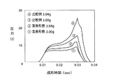
鍛造成形において金型が受ける素材からの反力を、実施形態のシューの場合と比較例のシューの場合とで、実際に比較した。反力が大きいということは、成形荷重を大きくしなければならないことを意味し、鍛造成形の際に素材が大きな力を受けることを意味する。なお、この比較は、CAE(computer-aided experiment:計算機援用実験)による解析である。シュー素材は、ともに前記アルミニウム合金であり、正規素材量を3.00gとし、その正規素材量の素材ピースから成形する状態と、正規素材量より0.04g多い素材量の素材ピースから成形する状態との2つの状態について、それぞれ評価した。その結果として、図12に、実施形態のシュー76および比較例のシュー250のそれぞれを鍛造成形した場合の、成形時間の経過に対する反力の変化を示し、図13に、両者の場合の、素材量の変化に対する最大反力の変化を示す。
【0070】
図12によれば、いずれのシューの場合も、成形開始から徐々に反力が増加し、シューの外周縁の部分への素材の塑性流動が始まるころから、反力の増加勾配が大きくなり、成形終了直前において、最大の反力となる。正規素材量の素材ピースから成形する場合について、実施形態のシューと比較例のシューとを比較すれば、上述の説明のとおり、比較例のシューのほうが反力が大きいことが判る。最大反力は、実施形態のシューの場合が約9t(トン)であるのに対し、比較例のシューが約15tと大きい。素材量を0.04g多くした場合について見れば、実施形態のシューおよび比較例のシューのいずれを鍛造成形する場合でも、素材からの反力は増加する。ところが、実施形態のシューの場合、最大反力が約12tであり、最大反力の増加量としては約3tと小さい。これに対し比較例のシューの場合は、最大反力が約26tであり、最大反力の増加量は11tと大きくなることが判る。この結果をプロットした図13は、実施形態のシューのほうが、素材量が増加した場合でも、反力が増加割合が小さいことを示している。以上の結果から、実施形態のシューは、比較例のシューに比べて、必要となる成形荷重が小さいことが容易に理解できる。また、実施形態のシューは、素材量のバラツキが生じても、素材が受ける力の差が小さいことから、寸法のバラツキは小さく、寸法精度の高いシューであることが確認できる。
【0071】
上記鍛造成形は、円柱形状の素材ピースから行っているが、球状の素材ピースを始めとして、各種形状の素材ピースから行うことができる。素材ピースの形状に関わらず、本発明のシューは、成形鍛造に必要な成形荷重が小さく、また、素材量の増加による反力の増加割合が小さく、寸法精度の高いシューとなる。
【0072】
なお、上記鍛造工程は、素材ピースから最終形状までの成形を一工程で行っているが、加工度の低いいくつかの鍛造成形を順次行うようにして、多工程で構成された鍛造工程とすることができる。例えば、一旦、中間的な形状(外周縁部の成形を行わない形状)にまで鍛造成形し、その後に、上述のように、外周縁部の成形を含めた鍛造成形を行うことができる。その場合は、後の鍛造成形を行う工程が、本発明の成形方法における鍛造工程となり、上記中間的形状のシュー前躯体が、素材ピースに該当することになる。また、最終形状に極めて近い形状(外周縁部の成形が殆ど完了した形状)にまで成形し、その後、寸法調整等を目的として、仕上鍛造成形を行うものであってもよい。この場合は、先の鍛造成形を行う工程が、本発明の成形方法における鍛造工程となる。なお、複数の工程による成形を行う場合、いずれかの工程間において、成形品に焼きなまし処理等を行うこともできる。
【0073】
鍛造工程で成形されたシューは、調質熱処理工程において、T6処理,T7処理(JIS H 0001)といった調質熱処理が行われる。また、研磨工程において、表面平滑化等のための研磨加工が行われる。この研磨加工では、平面研磨およびバレル研磨の2つの研磨加工を行う。平面研磨は、対斜板摺接面154の表面を研磨するものであり、平面研磨機により、いくつかのシューを整列させ、遊離砥粒を用いて行う。なお、この平面研磨において、対斜板摺接面154を中凸形状とすることもできる。バレル研磨は、シューの表面全体を研磨するものであり、バレル研磨機中に遊離砥粒とともにシューを投入して行う。なお、この2つ研磨加工は、いずれを先に行うものであってもよい。また、メッキ工程を行って、例えば、シューの表面に硬質金属メッキ被膜である無電解ニッケルメッキ被膜を施してもよい。仕上研磨工程において、研磨加工が施される。この仕上研磨工程では、主にバレル研磨を行い、必要とあらば平面研磨を行う。バフ研磨を行ってもよい。以上、説明した各工程を適当な順序で経て、上記シュー76が完成する。製造方法は、上述した製造方法に限定されるものでなく、本発明のシューは、製造対象とするシューの仕様に応じ、種々の態様の製造方法で製造することが可能である。
【0074】
以上の製造方法についての説明は、アルミニウム合金製のシューの製造方法を中心に行ってきたが、高炭素クロム軸受鋼等の鉄合金製のシューの場合は、例えば、上記鍛造工程後、必要とあれば焼入れ等の調質熱処理が施され、研磨工程、窒化処理工程、仕上研磨工程等を経てシューが完成する。なお、調質熱処理においては、熱歪み等によってシューが変形することも考えられる。その場合、その変形を見越して、鍛造工程における成形寸法を設定すればよい。かかる製造方法を採用し得るのも、本発明のシューおよび成形方法が寸法精度が高いことに依拠するものである。つまり、寸法精度の高いシューの成形が可能であることは、鍛造成形後の寸法調整を軽減でき、低コストにシューを製造できるというメリットにつながるのである。
【0075】
【図面の簡単な説明】
【図1】本発明の一実施形態であるシューが配設された斜板式圧縮機を示す正面断面図である。
【図2】図1に示す斜板圧縮機に配設されるシューを示す正面断面図である。
【図3】図2に示すシューが斜板と摺接している状態におけるつなぎ面を中心とした部分を拡大して示す断面図である。
【図4】本発明のもう一つの実施形態であるところの、周縁面が対斜板摺接面に対して傾斜するシューを示す断面図である。
【図5】上記実施形態のシューを鍛造によって成形する場合において用いられる素材ピースを示す。
【図6】本発明の実施形態である成形方法の素材ピース準備工程において、素材ピース基体に凹所を形成する様子を示す。
【図7】実施形態のシューを成形する鍛造工程の様子を模式的に示す。
【図8】実施形態のシューの鍛造成形におけるシュー外周部の素材の塑性流動の様子を示す。
【図9】比較例のシューを示す正面断面図である。
【図10】比較例のシューを成形する鍛造工程の様子を模式的に示す。
【図11】比較例のシューの鍛造成形におけるシュー外周部の素材の塑性流動の様子を示す。
【図12】実施形態のシューおよび比較例のシューのそれぞれを鍛造成形した場合の、成形時間の経過に対する反力の変化を示すグラフである。
【図13】実施形態のシューおよび比較例のシューのそれぞれを鍛造成形した場合の、素材量の変化に対する最大反力の変化を示すグラフである。
【符号の説明】
14:片頭ピストン 60:斜板 76:シュー 128:摺接面 132,134:摺接面 150:ピストン側係合面部 152:斜板側係合面部 154:対斜板摺接面 156:周縁面 158:つなぎ面 162:対ピストン摺接面 164:外周縁曲面 180:テーパ部 182:摺接側R部 184:周縁側R部 186:延長面 200:素材ピース 220:下型 222:上型 224:金型対 228:余剰空間[0001]
BACKGROUND OF THE INVENTION
The present invention relates to a shoe disposed between a swash plate and a piston in a swash plate compressor, and a molding method thereof.
[0002]
[Prior art]
The swash plate compressor converts the rotation of the swash plate into the reciprocating motion of the piston and compresses the gas. Between the swash plate rotating at high speed and the piston reciprocating at high speed, smooth operation of both is performed. In order to ensure, a shoe as a sliding member is provided. Since the swash plate is rotated at a high speed, the sliding characteristics between the swash plate and the shoe are required to be particularly good. The shoe has a spherical shape, that is, an outer surface having a generally convex spherical surface and engaging with a piston, and a swash plate side engaging surface having a generally flat surface and engaging with a swash plate. Often used are those having a shape that is generally partitioned into two. In this spherical crown shoe, it is desired that the sliding characteristics between the swash plate side sliding contact surface portion and the swash plate engaged therewith are particularly good. Specifically, for example, it is required that the supplied lubricating oil be sufficiently drawn between the sliding contact surfaces of both the shoe and the swash plate. It is required not to be drawn between the sliding contact surfaces so as not to damage the contact surfaces.
[0003]
In order to clear the requirement that seems to be a trade-off, the applicant of the present application has not yet disclosed a swash plate-side engagement surface portion and a piston-side engagement surface portion in an unpublished patent application (Japanese Patent Application No. 2001-139539). A spherical crown shoe is disclosed in which a side surface portion is provided between them, and the side surface portion is formed at an angle of, for example, 45 ° with respect to the surface of the swash plate. The shoe has good sliding characteristics.
[0004]
Like the general shoe, the above-disclosed shoe is formed by forging. The forging of the shoe includes a first mold having a mold surface for molding the piston-side engagement surface portion, and a second mold having a mold surface for molding the swash plate-side engagement surface portion and the side surface portion. This is done by using a pair of molds, placing the material piece in the center of the pair of molds, and closing the pair of molds. The material plastically flows inside the mold cavity toward the outer circumference, reaches the part that forms the side surface part of the mold surface, and plastically flows along that part from that state, firmly to the mold surface The shoe is formed by being pressed.
[0005]
[Problems to be solved by the invention, means for solving problems and effects]
The shoe is also required to have good dimensional accuracy. In particular, the height dimension (distance between the swash plate-side engaging surface portion and the piston-side engaging surface portion) is high because, for example, the tolerance for clearance variation is small due to the mechanism of the swash plate compressor. Accuracy is required. On the other hand, there is a demand for keeping the manufacturing cost as low as possible for a material piece to be subjected to forming forging, and there is a situation in which variation in the amount of material must be allowed to some extent.
[0006]
Against this background, the present inventors investigated the behavior of the forging material in the forging of the shoe in order to improve the dimensional accuracy of the shoe. In the mold pair, a portion where the side surface portion and the piston side engaging surface portion are connected is formed on the outer peripheral portion in the cavity, and the portion is a space for absorbing the variation in the material amount. Function as. However, as described above, since the side surface portion has a relatively large angle with respect to the swash plate surface, the mold surface for forming the side surface portion has a large resistance to plastic flow of the material, and as a result, For example, it has been found that when the amount of material is larger than the normal amount, the proportion of increase in reaction force from the material to the mold, increase in the amount of springback, etc. also increases. That is, when a shoe is manufactured by forging with a large resistance, the size of the formed shoe varies greatly due to the variation in the amount of material.
[0007]
Therefore, the present invention has been made with the object of obtaining a shoe for a swash plate compressor having good sliding characteristics and high dimensional accuracy. A machine shoe and a molding method thereof can be obtained. As with the claims, each aspect is divided into sections, each section is numbered, and is described in a form that cites the numbers of other sections as necessary. This is for the purpose of facilitating understanding of the present invention, and should not be construed as limiting the technical features described in the present specification and the combinations thereof to those described in the following sections. . In addition, when a plurality of items are described in one section, it is not always necessary to employ the plurality of items together. It is also possible to select and employ only some items.
[0008]
In each item below, item (1) To which the technical features of (6) are added Corresponds to claim 1, Claim 1 Item (2) and Item (3) Added technical features In claim 2, Claim 1 or claim 2 Item (4) With added technical features In claim 3, Any one of claims 1 to 3 Item (13) The technical feature of claim 4 is added. (21) The technical feature of (6) is added to claim 5 Respectively.
[0009]
(1) In the swash plate type compressor, a piston side engagement surface portion that is disposed between the swash plate and the piston and has an outer surface that forms a generally convex spherical surface and engages with the piston; A spherically shaped shoe that is generally divided into engaging swash plate side engaging surface portions,
The swash plate side engaging surface portion is
Constituting a central portion of the swash plate side engaging surface portion, and a substantially flat anti-swash plate sliding contact surface that is in sliding contact with the surface of the swash plate;
Forming a peripheral portion of the swash plate side engaging surface portion, retreating with a step from the anti-swash plate sliding contact surface, and a peripheral surface connecting to the piston side engaging surface portion at an outer peripheral edge;
An annular connecting surface connecting the peripheral surface and the antiswash plate sliding contact surface;
A swash plate type shoe for a compressor.
[0010]
Roughly speaking, the shoe described in this section is provided with a step which is retracted with respect to the central portion at the outer peripheral edge portion of the swash plate side engaging surface portion in a general spherical crown shoe. The outer peripheral edge of the anti-swash plate sliding contact surface ensures that the lubricating oil is drawn between the anti-swash plate sliding contact surface and the sliding contact surface of the swash plate, while drawing large foreign matter between the surfaces. It is desired to play a role of suppressing, and the above-described connecting surface existing at the level difference portion is an important existence. Although the specific shape of the connecting surface is not limited, for example, by adopting a configuration as described later, it is possible to have functions of drawing in lubricating oil and rejecting foreign matter. In the shoe described in the unpublished application, the side surface portion formed as a tapered surface fulfills the function, but the presence of the side surface portion is large when the forging material plastically flows when the shoe is forged. Causes resistance. On the other hand, in the shoe described in this section having no side portion, forging with high dimensional accuracy is possible because there is no portion that causes great resistance in forging. That is, a shoe having a higher dimensional accuracy and a sliding characteristic is secured. Further, when a shoe with insufficient dimensional accuracy is molded, for example, it takes a lot of time to adjust the size by polishing performed after molding, and the manufacturing cost of the shoe becomes extremely high. In that respect, the shoe described in this section can be said to be a shoe that can be manufactured at low cost.
[0011]
To explain the dimensional accuracy in more detail, when performing forging, the material piece is set at the center of the mold and the material is plastically flowed in the outer peripheral direction. As described above, in forging molding with high resistance, it is necessary to increase the molding load, and the reaction force from the material to the mold increases. When the force applied to the material and the mold is large, large elastic deformation occurs in both. For example, when a large elastic deformation occurs in the mold, the cavity shape also deforms. When a large elastic deformation occurs in the material, the amount of spring back after molding increases. If there is a fact that a certain amount of variation in the amount of material has to be allowed, even if a space for absorbing the variation is provided in the cavity, forging with high resistance is caused by the variation. Variations in the molding dimensions increase. In the shoe described in this section, in the forging process, the material can be plastically flowed so as to get over the level difference or to be covered with the level difference. It is possible. As a result, a shoe having high dimensional accuracy, particularly dimensional accuracy in the height direction of the shoe can be obtained. In other words, in the shoe described in this section, the outer peripheral edge portion of the shoe surrounded by the peripheral surface and the piston-side engagement surface portion can function as a portion that effectively absorbs the variation in material amount. . In summary, the shoe described in this section achieves both sliding characteristics and dimensional accuracy due to its shape-related features. By the way, when the accuracy of the height of the shoe is poor, for example, when the distance between the sliding contact surfaces of the shoe and the piston becomes too large, foreign matter easily enters, and when the distance between the sliding contact surfaces becomes too small. The friction between the two becomes excessive, and the sliding characteristics are lowered at any time.
[0012]
Here, the spherical crown-shaped shoe is generally referred to as a hemispherical shoe because it has the shape described above, in other words, a shape in which the side engaged with the piston is substantially spherical and the side engaged with the swash plate is substantially flat. Has been. However, it is not necessarily strictly spherical or flat, and is often slightly deviated from the spherical or flat surface for the purpose of improving sliding performance. For example, the anti-swash plate sliding contact surface may be formed as a middle convex shape (for example, a convex spherical surface having a very large radius of curvature) whose center is swollen by about 0.5 to 10 μm compared to the peripheral edge. The crown-shaped shoe referred to in the specification includes a shoe having such a shape. In addition, the shoe described in this section can be used for both variable capacity and fixed capacity swash plate type compressors, but those for variable capacity compressors are smaller than hemispheres, and for fixed capacity compressors. Things are usually made larger than the hemisphere. In a variable displacement compressor, it is necessary that the spherical surfaces of a pair of shoes disposed on both sides of the swash plate should be located substantially on one spherical surface, so that the thickness of the swash plate is half that of the hemisphere. In the fixed capacity type compressor, since there is no restriction as described above, it is slightly larger than the hemisphere for the purpose of preventing the area of the sliding contact surface from being reduced even when the flat portion of the shoe is worn. It is often done. Therefore, in this specification, both types of shoes are collectively referred to as a spherical crown shoe.
[0013]
(2) The shoe for a swash plate compressor according to (1), wherein a step between the swash plate sliding contact surface and the peripheral surface is 0.02 mm or more.
(3) The swash plate type compressor shoe according to any one of (1) or (2), wherein a step between the anti-swash plate sliding contact surface and the peripheral surface is 0.5 mm or less.
[0014]
The “step between the antiswash plate sliding contact surface and the peripheral surface” means the distance between the extended surface of the antiswash plate sliding contact surface and the edge of the peripheral surface connected to the connecting surface. When the antiswash plate sliding contact surface is a flat surface and the peripheral surface and the antiswash plate sliding contact surface are parallel to each other, the distance between both surfaces is obtained. When the anti-swash plate sliding contact surface has the above-described middle convex shape, the “extension surface of the anti-swash plate sliding contact surface” is in contact with the anti-swash plate sliding contact surface perpendicular to the shoe center line. Treat as a plane. In other words, in this case, the sliding surface of the swash plate and the peripheral surface when the shoe is brought into sliding contact with the swash plate in a straight state (the center line of the shoe is perpendicular to the sliding contact surface of the swash plate). This is equivalent to the separation distance from the end portion.
[0015]
The amount of the step between the antiswash plate sliding surface and the peripheral surface affects the characteristics of the shoe. For example, when the level difference is too small, it is difficult for the lubricating oil to be drawn between the sliding contact surface of the swash plate and the anti-swash plate sliding contact surface of the shoe. Considering this, the step is desirably 0.02 mm or more. Also, the smaller the step, the easier it is for small foreign objects to bite between the peripheral surface and the swash plate surface. Further, as the level difference becomes smaller, there is a possibility that a connecting surface having an appropriate shape capable of exhibiting a function of drawing in lubricating oil and a function of rejecting foreign matters may not be formed due to restrictions on the shape of the connecting surface. In view of these, it is desirable that the step be 0.05 mm or more. In addition, it is more desirable to be 0.1 mm or more, and even more desirable to be 0.15 mm or more from the viewpoint that even larger foreign matter is not caught. On the contrary, when the level difference is large, the resistance to the plastic flow of the material in the forging as described above increases. Considering this point, the size of the step is preferably 0.5 mm or less. From the viewpoint of further reducing the resistance, it is more preferably 0.3 mm or less, and further preferably 0.25 mm or less.
[0016]
(4) The swash plate type compressor shoe according to any one of (1) to (3), wherein the peripheral surface and the anti-swash plate sliding contact surface are substantially parallel.
(5) The peripheral surface is inclined with respect to the antiswash plate sliding contact surface, and an angle formed by the peripheral surface and an extended surface of the antiswash plate sliding contact surface is 10 ° or less. Or a shoe for a swash plate compressor according to any one of (3).
[0017]
From the viewpoint of reducing the resistance to plastic flow of the material in forging, the peripheral surface is preferably substantially parallel to the anti-swash plate sliding contact surface as in the aspect described in the item (4). . Further, even if not parallel, as in the aspect described in (5), when it is gently inclined with respect to the anti-swash plate sliding contact surface, its resistance is relatively small, This can be an aspect of the shoe of the present invention.
[0018]
(6) The connecting surface includes a tapered portion having a truncated cone peripheral surface shape that expands toward the peripheral surface, and a corner R portion that connects the tapered portion and the antiswash plate sliding contact surface. Or a shoe for a swash plate compressor according to any one of (5) to (5).
[0019]
As described above, in sliding between the shoe and the swash plate, the lubricating oil is sufficiently drawn between the sliding contact surface of the shoe and the sliding contact surface of the swash plate, and no harmful foreign matter enters. If these requirements are not satisfied, good sliding characteristics cannot be obtained. Taking a swash plate type compressor constituting an air conditioner as an example, the drawing of lubricating oil and the removal of foreign matter will be described in detail here. Lubricating oil is mixed in the refrigerant gas, and the lubricating oil forms an oil film between both sliding contact surfaces, so that the sliding characteristics between the shoe and the swash plate are maintained well. Therefore, when the lubricating oil is not sufficiently drawn between both sliding contact surfaces, the sliding characteristics are deteriorated. Further, various foreign matters such as shavings generated by friction at various places during operation, minute burrs generated and remaining in the manufacturing process of each component, dust introduced from the connected refrigerant pipe, and the like can exist. Although these foreign matters should be sufficiently managed, it is difficult to eliminate them completely, and there is a possibility that foreign matters are attracted and interposed between the sliding contact surfaces of both the swash plate and the shoe. When a foreign object is interposed between both sliding surfaces, both sliding surfaces are damaged by the foreign material, and the sliding characteristics are deteriorated. In order to satisfy both the pull-in characteristic of the lubricating oil and the foreign-matter elimination characteristic, the shape of the peripheral portion of the sliding surface of the shoe that is in sliding contact with the swash plate is important. In the shoe of the present invention, specifically, these requirements can be satisfied by adjusting the shape of the connecting surface adjacent to the periphery of the anti-swash plate sliding contact surface. The aspect described in this section is one aspect thereof. By adjusting the shape of the tapered portion and the corner R portion, the lubricating oil pull-in characteristic and the foreign matter rejecting characteristic can be arbitrarily adjusted, and a shoe having excellent sliding characteristics can be obtained.
[0020]
Further, when the tapered portion and the swash plate sliding contact surface are directly adjacent to each other, that is, when the corners on both sides have a so-called pin angle, the corners rub against the swash plate surface. For example, a lubrication film containing a solid lubricant, for example, may be formed on the sliding surface of the swash plate to further ensure lubricity, and the lubrication film has relatively low strength and hardness. In such a case, the corner of the pin angle of the shoe also acts to peel off the lubricant film. Further, when the pin angle is used, it is considered that the lubricating oil is discharged, and it becomes difficult to introduce sufficient lubricating oil between the sliding contact surfaces of the shoe and the swash plate. Furthermore, the shoes are often barrel-polished after molding in order to smooth the surface, and shoes having pin angle corners are likely to collide with each other in this barrel polishing and have dents. Furthermore, there is a shoe with a metal plating film formed on the surface, and when such a shoe has a pin angle corner, the metal plating film at the corner portion is worn by barrel polishing, and the base material may be exposed. There is also sex. Both of these phenomena are disadvantages due to the pin angle of the corner. In the shoe described in this section, the tapered portion and the swash plate side sliding contact surface are adjacent to each other with the corner R portion interposed therebetween. In other words, the corner is rounded, and the above-described disadvantages are alleviated. It becomes a shoe of good quality.
[0021]
The tapered portion is defined as having a frustoconical surface shape that expands toward the peripheral surface. However, since the tapered portion is provided at a relatively small stepped portion, its length (distance in the shoe height direction). ) Is short. The connecting surface may be configured to have another corner R portion that connects the peripheral surface and the tapered portion separately from the above corner R portion due to manufacturing reasons and the like. When it is small or when the two corners R are relatively large, the length of the tapered portion is extremely small. In the ultimate state, the length is almost zero. In the aspect described in this section, the tapered portion includes those in the ultimate state. That is, in that case, the boundary portion between the two corner R portions is regarded as a tapered portion.
[0022]
(7) The shoe for a swash plate compressor according to (6), wherein an angle formed between the tapered portion and an extended surface of the swash plate sliding contact surface is 35 ° or more.
(8) The shoe for a swash plate compressor according to (6) or (7), wherein an angle formed by the tapered portion and an extended surface of the swash plate sliding contact surface is 90 ° or less.
[0023]
The angle of the taper portion (referred to as “the angle formed by the taper portion and the extended surface of the anti-swash plate sliding surface”). In some cases, the lubricating oil pull-in characteristics are good. However, the taper angle is too small When, Foreign matter rejection characteristics are reduced. In other words, the taper part can easily ride on foreign matter, and if the shoe moves while riding, the foreign matter will be drawn between the swash plate side sliding contact surface of the shoe and the sliding contact surface of the swash plate. is there. On the other hand, if the angle of the taper portion is increased up to 90 °, the taper surface acts to push away foreign matter. That is, the foreign substance rejection characteristic becomes better as the angle of the tapered portion becomes larger. When a foreign object enters between both sliding contact surfaces, the foreign material not only increases the friction of the sliding contact surface but also damages each sliding contact surface. The scratches generated in each of them will further damage each other and cause deterioration of sliding characteristics. Also, if the angle of the taper part is small, the shoe will ride on the foreign material, so the foreign material will be forced into the narrow sliding surface and the scratches on the sliding surface of the shoe and swash plate will be deep. It becomes. Therefore, deep scratches are likely to occur, and in this sense, the resistance to foreign matter, that is, the foreign matter resistance, is inferior, and a shoe with a small taper angle has poor sliding characteristics. On the other hand, even if the angle of the taper portion is large, the step is relatively small, so that resistance to plastic flow of the material in forging is less likely to be a cause of deteriorating the dimensional accuracy of the shoe.
[0024]
In view of the above, the angle of the tapered portion is preferably 35 ° or more, and more preferably 40 ° or more in order to obtain higher foreign matter rejection characteristics. The angle of the taper portion is desirably 90 ° or less, and it is set to 75 ° or less in consideration of the lubricating oil pulling characteristics and the smaller resistance of the forging process as the taper portion angle becomes smaller. Desirably, 60 ° or less is more desirable, and 50 ° or less is even more desirable.
[0025]
In the ultimate state where the length of the taper portion is almost zero as described above, the angle of the boundary portion between the two corner R portions described above, that is, including the diameter, is perpendicular to the swash plate sliding contact surface. The angle between the tangent line in contact with the two corners R and the extended surface of the anti-swash plate sliding surface in the cross section of the shoe cut along a plane is defined as the angle of the tapered portion. In addition, when the antiswash plate sliding contact surface has a middle convex shape, the “extension surface of the antiswash plate sliding contact surface” is orthogonal to the shoe center line and is the antiswash plate sliding contact surface as described above. Treat as a tangent plane. That is, when the shoe is brought into sliding contact with the swash plate in a straight state, the angle formed between the sliding contact surface of the swash plate and the tapered portion corresponds to the angle of the tapered portion.
[0026]
(9) The shoe for a swash plate compressor according to any one of (6) to (8), wherein a radius of curvature of the corner R portion is 0.05 mm or more.
(10) The shoe for a swash plate compressor according to any one of (6) to (9), wherein a radius of curvature of the corner R portion is 0.5 mm or less.
[0027]
The effect of alleviating the above disadvantages by providing the corner R portion, that is, the effect of pulling the lubricating oil between the sliding contact surfaces, suppressing the dent of the shoe in the barrel polishing process, suppressing the wear of the metal plating film, etc. is substantially obtained. Therefore, it is desirable that the corner has a radius of curvature of 0.05 m or more. In addition, the effect becomes higher as the radius of curvature is larger to a certain extent. Therefore, if the effect is regarded as important, the radius of curvature of the corner R portion is more preferably 0.1 mm or more, and further preferably 0.15 mm or more. Conversely, when the radius of curvature of the corner R portion is increased, relatively small foreign matter comes into contact with the corner R portion instead of the tapered portion. In this case, the characteristic of rejecting foreign matter depends on the angle formed between the contact plane with the corner R portion at the contact point with the foreign matter and the extended surface of the swash plate side sliding contact surface. When contacting a foreign object at the corner R and rejecting the foreign object, the larger the tangential plane angle, the better the foreign object rejection characteristic. The smaller the radius of curvature of the corner R, the larger the tangential plane angle when a foreign substance of the same size contacts the corner R portion. That is, the smaller the radius of curvature of the corner R portion, the better the foreign matter rejection characteristic. Therefore, according to that, the radius of curvature of the corner R is desirably 0.5 mm or less, more desirably 0.4 mm or less, and further desirably 0.3 mm or less.
[0028]
(11) The shoe for a swash plate compressor according to any one of (1) to (10), wherein the base material is made of an aluminum alloy.
(12) The shoe for a swash plate compressor according to any one of (1) to (10), wherein the base material is made of high carbon chromium bearing steel.
[0029]
The material of the base material of the shoe of the present invention is not limited. It can be formed of various metal materials. Since a shoe made of an aluminum alloy as a base material is lightweight, the shoe is suitable for a swash plate compressor that is particularly desired to be reduced in weight, such as a swash plate compressor used for a vehicle air conditioner or the like. It becomes. The type of aluminum alloy is not limited. Aluminum-based alloys that are already commonly used in various fields, and various known aluminum-based alloys can be used. More specifically, for example, an Al—Si alloy near the eutectic composition such as A4032 (JIS H 4000 or the like) can be used. An Al—Si alloy has a small coefficient of thermal expansion and good wear resistance. If this alloy is used, a shoe having good sliding characteristics can be obtained. Further, for example, an Al-Cu-Mg alloy such as A2017, A2024 (JIS H 4000, etc.) can be used. Since the Al—Cu—Mg alloy has high strength, the use of this alloy provides a shoe having high strength and excellent durability. The aluminum alloy is preferably coated on the surface with a hard metal plating film, and the hard metal plating film is preferably an electroless nickel plating film such as Ni-P or Ni-B. In addition to being able to form a uniform hard metal plating film, the electroless nickel plating film has a high Vickers hardness of more than Hv500 at the time of deposition, and is resistant to wear and corrosion. Excellent for sex It is. The aluminum alloy shoe is often forged from a cylindrical material piece, and the cylindrical material piece has a large variation in material amount. The merit of applying is great.
[0030]
The shoe of the present invention may be made of an iron alloy. Iron-based alloys are inexpensive and have relatively high strength and hardness. Therefore, the shoe described in this section is inexpensive and has excellent wear resistance and durability. The type of iron-based alloy is not limited, but high-carbon chromium bearing steel (specifically SUJ2 (JIS G) is used because it is extremely hard and has excellent wear resistance and heat resistance. 4805)) is desirable. In the case of a shoe made of high carbon chrome bearing steel, it is desirable to manufacture by performing tempering heat treatment such as quenching and tempering, nitriding treatment and the like. Note that a shoe made of high carbon chromium bearing steel requires a larger molding load for forging than a shoe made of aluminum alloy. Since the shoe of the present invention can easily cause plastic flow of a material in forging even if there is a variation in the material, an effect such as a reduction in the cost of the mold can be obtained. The merit of applying the present invention to a shoe made is great.
[0031]
It should be noted that the shoe of the present invention is not limited to the aluminum alloy and the iron alloy as described above. The above description does not preclude the use of other metal materials such as magnesium, resin or the like as the base material of the shoe.
[0032]
(13) The shoe includes a first mold having a mold surface for forming the piston-side engagement surface portion, and a second mold having a mold surface for forming the swash plate-side engagement surface portion. Using a mold pair, a material piece having an outer diameter smaller than the diameter of the swash plate sliding contact surface is set at the center of the mold pair, and forged by closing the mold pair. A shoe for a swash plate compressor according to any one of (1) to (12).
(14) The shoe for a swash plate compressor according to (13), which is forged from the cylindrical piece of material.
[0033]
As described above, the shoe of the present invention can easily cause plastic flow of the material in forging due to its shape characteristics. Therefore, the advantage of the forged shoe is sufficiently exhibited. The shape of the material piece is not particularly limited, and may be forged from a spherical material piece. In that case, a material piece with less variation in material amount can be manufactured by performing processing steps such as flushing and grinding as in the case of manufacturing a bearing ball. Moreover, it may be forged from a cylindrical material piece. A cylindrical material piece can be prepared at low cost by cutting a bar, but the amount of material varies greatly. In particular, in the case of shearing cutting or the like, it is cheaper, but the variation in the amount of material is larger. Since the shoe of the present invention has good dimensional accuracy after being forged even if there is variation in the amount of material, the advantage of applying the present invention to a shoe forged from a cylindrical material piece Will be big.
[0034]
(21) In the swash plate compressor, a piston side engagement surface portion that is disposed between the swash plate and the piston and has an outer surface that is generally convex and engages with the piston, and a swash plate that is generally flat. The swash plate side engagement surface portion is generally partitioned, and the swash plate side engagement surface portion constitutes a central portion of the swash plate side engagement surface portion and is in sliding contact with the surface of the swash plate. A flat anti-swash plate sliding contact surface, and (b) a peripheral portion of the swash plate side engaging surface portion, retreating with a step from the anti-swash plate sliding contact surface, and the piston side engagement at the outer peripheral edge A method of forming a spherical crown-shaped shoe having a peripheral surface connected to a mating surface, and (c) an annular connecting surface connecting the peripheral surface and the anti-swash plate sliding contact surface,
A material piece preparation step of preparing a material piece having an outer diameter smaller than the outer diameter of the anti-swash plate sliding surface;
Using a mold pair including a first mold having a mold surface for molding the piston side engagement surface portion and a second mold having a mold surface for molding the swash plate side engagement surface portion, A forging process in which the material piece is set at the center of the mold pair, the mold pair is closed and the spherical crown shoe is forged;
A method for forming a shoe for a swash plate compressor, comprising:
(22) The method for forming a shoe for a swash plate compressor according to (21), wherein the material piece preparation step prepares a cylindrical material piece.
[0035]
The molding method of the present invention is the shoe molding method of the present invention described above, using a mold pair consisting of two molds separated in the vicinity of the boundary between the piston side engaging surface portion and the swash plate side engaging surface portion. Forging is performed by crushing the material piece in the shoe height direction and plastically flowing the material in the outer peripheral direction. Due to the above-mentioned geometric characteristics, the plastic flow is performed smoothly, and even if there is a variation in the amount of material, a large molding load is not required. As a result, the molded shoe has a dimensional accuracy, especially in the height direction. Will be good. Further, as described above, even if there is a variation in the amount of material, according to the present molding method, the shoe can be manufactured with high dimensional accuracy. Therefore, if an inexpensive cylindrical material piece is used, an inexpensive shoe can be obtained. it can. It should be noted that the shoe and the mold pair to be molded by the molding method of the present invention have a mode in which the technical features described in the above items (2) to (20) are limited. There may be.
[0036]
(31) A swash plate and a piston are provided, and the shoe according to any one of the items (1) to (14) is disposed between the swash plate and the piston. A swash plate compressor.
The swash plate compressor of the present invention is a swash plate compressor provided with the shoe of the present invention, and is a swash plate compressor having good sliding characteristics.
[0037]
DETAILED DESCRIPTION OF THE INVENTION
Hereinafter, as an embodiment of the present invention, a variable capacity swash plate compressor used in a vehicle air conditioner and a spherical crown shoe as a component thereof will be described as an example and described in detail with reference to the drawings. For convenience of explanation, the overall configuration of the swash plate compressor will be described first, then the shape of the shoe and the sliding contact state between the shoe and the swash plate will be described, followed by a method for manufacturing the shoe. To do. The present invention is by no means limited to the following embodiments. In addition to the following embodiments, the embodiments described in the above [Problems to be Solved, Problem Solving Means and Effects] are described. As described above, the present invention can be implemented in various modifications and improvements based on the knowledge of those skilled in the art.
[0038]
<Overall configuration of swash plate compressor>
FIG. 1 shows a swash plate compressor of the present invention. In FIG. 1,
[0039]
A
[0040]
A
[0041]
The
[0042]
The rotational movement of the
[0043]
An
[0044]
A
[0045]
The swash plate compressor is of a variable capacity type, and the pressure in the
[0046]
The
[0047]
The engaging
[0048]
The base material of the
[0049]
<Shoe shape, etc. and sliding contact between shoe and swash plate>
FIG. 2 shows a front sectional view of the
[0050]
More specifically, referring to FIG. 1 as well, the pair of
[0051]
The
[0052]
FIG. 3 is an enlarged view of a portion around the connecting
[0053]
FIG. 3 shows a state in which the
[0054]
In a state in which the
[0055]
The
[0056]
In the case of the above embodiment, the step amount D between the
[0057]
<Shoe manufacturing method>
An example of a method for manufacturing the
[0058]
The material is the above-described aluminum alloy, and the material piece formed from the material is shown in the figure. Shown in 5 As shown, it has a cylindrical shape. Specifically, the
[0059]
FIG. 6 shows how the
[0060]
The material piece preparation process is completed as described above. The material piece preparation step is not limited to the above form. For example, when a shoe is formed using a spherical material piece, the material piece is a step of manufacturing a spherical material. In that case, various processes such as cutting and pressing the rod-shaped material, and then flushing and grinding are combined. Moreover, when forging using the raw material piece which does not have a recess, formation of a recess becomes unnecessary in the said raw material piece preparation process. In addition, the person who performs the forging process does not need to perform the material piece preparation process, and may purchase and procure a predetermined material piece and perform forging using the material piece. In that case, the material piece preparation step is a step of procuring material pieces.
[0061]
Next, the
[0062]
More specifically, the mold surface of the
[0063]
The cavity of the
[0064]
When the
[0065]
FIG. 8 shows the plastic flow of the material on the outer periphery of the shoe. In the forging of the
[0066]
For comparison, the above-described shoe provided with the side surface connecting the swash plate side engaging surface portion and the piston side engaging surface portion and forging of the shoe will be described. FIG. 9 shows a front sectional view of the above shoe as a comparative example. The outer surface of the
[0067]
In FIG. 10, the mode of the forge process which shape | molds the
[0068]
FIG. 11 shows the state of plastic flow of the material on the outer periphery of the shoe in the
[0069]
The reaction force from the material received by the mold in forging was actually compared between the shoe of the embodiment and the shoe of the comparative example. A large reaction force means that the molding load must be increased, and means that the material receives a large force during forging. This comparison is an analysis by CAE (computer-aided experiment). The shoe material is both the aluminum alloy, the normal material amount is set to 3.00 g, the state is formed from the material piece of the normal material amount, and the state is formed from the material piece of the material amount 0.04 g larger than the normal material amount. Each of the two states was evaluated. As a result, FIG. 12 shows changes in reaction force with respect to the lapse of molding time when each of the
[0070]
According to FIG. 12, in any shoe, the reaction force gradually increases from the start of molding, and the increasing gradient of the reaction force increases from the time when the plastic flow of the material to the outer peripheral portion of the shoe begins. Immediately before the end of molding, the maximum reaction force is obtained. In the case of molding from a material piece of a regular material amount, if the shoe of the embodiment and the shoe of the comparative example are compared, it can be seen that the reaction force of the shoe of the comparative example is larger as described above. The maximum reaction force is about 9 t (tons) in the case of the shoe of the embodiment, whereas it is as large as about 15 t in the shoe of the comparative example. If the amount of the material is increased by 0.04 g, the reaction force from the material increases regardless of whether the shoe of the embodiment or the shoe of the comparative example is forged. However, in the shoe of the embodiment, the maximum reaction force is about 12 t, and the increase amount of the maximum reaction force is as small as about 3 t. On the other hand, in the case of the shoe of the comparative example, the maximum reaction force is about 26 t, and the increase amount of the maximum reaction force is as large as 11 t. FIG. 13 in which the results are plotted shows that the shoe of the embodiment has a smaller reaction force increase rate even when the amount of material increases. From the above results, it can be easily understood that the shoe of the embodiment requires a smaller molding load than the shoe of the comparative example. In addition, even if the amount of material varies, the shoe of the embodiment has a small difference in force applied to the material. Therefore, it can be confirmed that the shoe has a small size variation and high dimensional accuracy.
[0071]
The forging is performed from a cylindrical material piece, but can be performed from various shaped material pieces including a spherical material piece. Regardless of the shape of the material piece, the shoe of the present invention has a small molding load required for molding and forging, and the rate of increase in reaction force due to the increase in the amount of material is small, so that the shoe has high dimensional accuracy.
[0072]
In addition, although the said forging process is performing the shaping | molding from a raw material piece to the last shape in one process, it is set as the forging process comprised by multiple processes by performing several forging shaping | moldings with a low workability one by one. be able to. For example, it can be once forged to an intermediate shape (a shape in which the outer peripheral edge is not formed), and then forged including the outer peripheral edge as described above. In this case, the subsequent forging process is a forging process in the molding method of the present invention, and the intermediate shoe shoe casing corresponds to the material piece. Moreover, it may shape | mold to the shape very close to the final shape (shape in which shaping | molding of the outer-periphery edge part was completed), and may perform finish forge shaping | molding for the purpose of a dimension adjustment etc. after that. In this case, the process for performing the previous forging is the forging process in the molding method of the present invention. In addition, when shaping | molding by a some process, an annealing process etc. can also be performed to a molded article between any processes.
[0073]
The shoe formed in the forging process is subjected to tempering heat treatment such as T6 treatment and T7 treatment (JIS H 0001) in the tempering heat treatment step. In the polishing process, polishing for surface smoothing or the like is performed. In this polishing process, two polishing processes are performed: planar polishing and barrel polishing. The surface polishing is for polishing the surface of the anti-swash plate sliding
[0074]
The above description of the manufacturing method has been centered on a method for manufacturing an aluminum alloy shoe, but in the case of a shoe made of an iron alloy such as high carbon chrome bearing steel, for example, after the forging step, it is necessary. If there is a tempering heat treatment such as quenching, the shoe is completed through a polishing process, a nitriding process, a finish polishing process, and the like. In the tempering heat treatment, the shoe may be deformed due to thermal strain or the like. In that case, what is necessary is just to set the shaping | molding dimension in a forge process in anticipation of the deformation | transformation. Such a manufacturing method can be adopted because the shoe and the molding method of the present invention have high dimensional accuracy. In other words, the ability to form a shoe with high dimensional accuracy leads to the advantage that the dimensional adjustment after forging can be reduced and the shoe can be manufactured at low cost.
[0075]
[Brief description of the drawings]
FIG. 1 is a front sectional view showing a swash plate type compressor provided with a shoe according to an embodiment of the present invention.
FIG. 2 is a front sectional view showing a shoe disposed in the swash plate compressor shown in FIG. 1;
3 is an enlarged cross-sectional view showing a portion centering on a connecting surface in a state where the shoe shown in FIG. 2 is in sliding contact with the swash plate. FIG.
FIG. 4 is a cross-sectional view showing a shoe according to another embodiment of the present invention, the peripheral surface of which is inclined with respect to the anti-swash plate sliding contact surface.
FIG. 5 shows a material piece used when the shoe of the embodiment is formed by forging.
FIG. 6 shows a state in which a recess is formed in the material piece base in the material piece preparation step of the molding method according to the embodiment of the present invention.
FIG. 7 schematically shows a forging process for forming the shoe of the embodiment.
FIG. 8 shows a state of plastic flow of the material on the outer periphery of the shoe in the forging of the shoe according to the embodiment.
FIG. 9 is a front sectional view showing a shoe of a comparative example.
FIG. 10 schematically shows a forging process for forming a shoe of a comparative example.
FIG. 11 shows a state of plastic flow of the material on the outer periphery of the shoe in the forging of the shoe of the comparative example.
FIG. 12 is a graph showing a change in reaction force with the lapse of molding time when each of the shoe of the embodiment and the shoe of the comparative example is forged.
FIG. 13 is a graph showing a change in maximum reaction force with respect to a change in material amount when each of the shoe of the embodiment and the shoe of the comparative example is forged.
[Explanation of symbols]
14: One-head piston 60: Swash plate 76: Shoe 128: Sliding
Claims (5)
前記斜板側係合面部が、
その斜板側係合面部の中央部分を構成し、前記斜板の表面に摺接する略平坦な対斜板摺接面と、
前記斜板側係合面部の周縁部分を構成し、前記対斜板摺接面から段差を有して後退し、外周縁において前記ピストン側係合面部につながる周縁面と、
その周縁面に向かうに従って拡がる円錐台周面形状をなすテーパ部と、そのテーパ部と前記対斜板摺接面とをつなぐコーナR部とを有して、前記周縁面と前記対斜板摺接面とをつなぐ環状のつなぎ面と
を有することを特徴とする斜板式圧縮機用シュー。In the swash plate type compressor, the outer surface is disposed between the swash plate and the piston, and the outer surface engages with the piston in a generally convex spherical surface, and engages with the swash plate in a generally flat surface. A spherical crown-shaped shoe roughly divided into a swash plate side engaging surface part,
The swash plate side engaging surface portion is
Constituting a central portion of the swash plate side engaging surface portion, and a substantially flat anti-swash plate sliding contact surface that is in sliding contact with the surface of the swash plate;
Forming a peripheral portion of the swash plate side engaging surface portion, retreating with a step from the anti-swash plate sliding contact surface, and a peripheral surface connecting to the piston side engaging surface portion at an outer peripheral edge;
A taper portion having a truncated cone peripheral surface shape extending toward the peripheral surface, and a corner R portion connecting the taper portion and the antiswash plate sliding contact surface; A shoe for a swash plate compressor, characterized by having an annular connecting surface connecting the contact surface.
前記対斜板摺接面の外径より小さな外径を有する素材ピースを準備する素材ピース準備工程と、
前記ピストン側係合面部を成形する型面を有する第1の金型と、前記斜板側係合面部を成形する型面を有する第2の金型とを備えた金型対を用い、その金型対の中央に前記素材ピースをセットし、その金型対を閉型して前記球冠状シューを鍛造する鍛造工程と
を含むことを特徴とする斜板式圧縮機用シューの成形方法。In the swash plate type compressor, the outer surface is disposed between the swash plate and the piston, and the outer surface engages with the piston in a generally convex spherical surface, and engages with the swash plate in a generally flat surface. The swash plate side engaging surface portion is substantially partitioned, and the swash plate side engaging surface portion forms (a) a central portion of the swash plate side engaging surface portion, and is a substantially flat pair slidably contacting the surface of the swash plate. A swash plate sliding contact surface, and (b) a peripheral portion of the swash plate side engaging surface portion, retreating with a step from the anti-swash plate sliding contact surface, and at the outer peripheral edge to the piston side engaging surface portion A connecting peripheral surface, (c) a tapered portion having a frustoconical peripheral surface shape that expands toward the peripheral surface, and a corner R portion that connects the tapered portion and the antiswash plate sliding contact surface, A method of forming a spherical crown shoe having an annular connecting surface connecting a peripheral surface and the anti-swash plate sliding contact surface,
A material piece preparation step of preparing a material piece having an outer diameter smaller than the outer diameter of the anti-swash plate sliding surface;
Using a mold pair including a first mold having a mold surface for molding the piston side engagement surface portion and a second mold having a mold surface for molding the swash plate side engagement surface portion, And a forging step of forging the spherical crown shoe by setting the material piece in the center of the mold pair, and closing the mold pair to form a shoe for a swash plate compressor.
Priority Applications (6)
| Application Number | Priority Date | Filing Date | Title |
|---|---|---|---|
| JP2002061513A JP3985552B2 (en) | 2002-03-07 | 2002-03-07 | Shoe for a swash plate compressor and method for forming the same |
| KR1020020082595A KR20030074110A (en) | 2002-03-07 | 2002-12-23 | Shoe for swash type compressor and manufacturing method thereof |
| US10/382,189 US20030209137A1 (en) | 2002-03-07 | 2003-03-05 | Shoe for use in swash plate type compressor and method of forming the same |
| CN03122652A CN1443940A (en) | 2002-03-07 | 2003-03-06 | Piston shoes for oblique disk type compressor |
| EP03004888A EP1342919A3 (en) | 2002-03-07 | 2003-03-06 | Shoe for use in swash plate type compressor and method of forming the same |
| BR0300404-0A BR0300404A (en) | 2002-03-07 | 2003-03-07 | Shoe for use on swash plate compressor and method for forming the same |
Applications Claiming Priority (1)
| Application Number | Priority Date | Filing Date | Title |
|---|---|---|---|
| JP2002061513A JP3985552B2 (en) | 2002-03-07 | 2002-03-07 | Shoe for a swash plate compressor and method for forming the same |
Publications (3)
| Publication Number | Publication Date |
|---|---|
| JP2003262186A JP2003262186A (en) | 2003-09-19 |
| JP2003262186A5 JP2003262186A5 (en) | 2005-03-17 |
| JP3985552B2 true JP3985552B2 (en) | 2007-10-03 |
Family
ID=27751195
Family Applications (1)
| Application Number | Title | Priority Date | Filing Date |
|---|---|---|---|
| JP2002061513A Expired - Lifetime JP3985552B2 (en) | 2002-03-07 | 2002-03-07 | Shoe for a swash plate compressor and method for forming the same |
Country Status (6)
| Country | Link |
|---|---|
| US (1) | US20030209137A1 (en) |
| EP (1) | EP1342919A3 (en) |
| JP (1) | JP3985552B2 (en) |
| KR (1) | KR20030074110A (en) |
| CN (1) | CN1443940A (en) |
| BR (1) | BR0300404A (en) |
Families Citing this family (8)
| Publication number | Priority date | Publication date | Assignee | Title |
|---|---|---|---|---|
| JP2007198156A (en) * | 2006-01-24 | 2007-08-09 | Sanden Corp | Variable displacement swash plate type compressor |
| DE102006008437A1 (en) * | 2006-02-23 | 2007-10-04 | Schaeffler Kg | Sliding shoe for a swash plate gear |
| JP5391667B2 (en) * | 2008-03-12 | 2014-01-15 | 日本精工株式会社 | Manufacturing method of sliding shoe for swash plate compressor |
| KR101327059B1 (en) | 2011-03-09 | 2013-11-07 | 현대자동차주식회사 | Swash plate and method for manufacturing thereof |
| JP6542984B2 (en) * | 2015-09-02 | 2019-07-10 | ジョン、グ ワンJUNG, Gu Wang | Pipe expansion punch |
| WO2017183669A1 (en) * | 2016-04-20 | 2017-10-26 | Ntn株式会社 | Hemispherical shoe for swash plate compressor, and swash plate compressor |
| JP6937100B2 (en) | 2016-09-30 | 2021-09-22 | 大豊工業株式会社 | Compressor shoe |
| US11806964B2 (en) * | 2021-08-31 | 2023-11-07 | Honeywell Federal Manufacturing & Technologies, Llc | Dopant for improving casting and electroplating performance |
Family Cites Families (7)
| Publication number | Priority date | Publication date | Assignee | Title |
|---|---|---|---|---|
| DE3627652A1 (en) * | 1985-08-16 | 1987-03-05 | Toyoda Automatic Loom Works | SLIDING SHOE FOR A SWASH DISC COMPRESSOR |
| JPH0724913B2 (en) * | 1987-12-18 | 1995-03-22 | 株式会社リケン | Cold forging method for shoes for swash plate compressors |
| JP3495225B2 (en) * | 1997-06-25 | 2004-02-09 | サンデン株式会社 | Method of manufacturing shoe for swash plate type compressor |
| JPH1122640A (en) * | 1997-07-08 | 1999-01-26 | Riken Corp | Shoe for swash plate compressor |
| JPH11218077A (en) * | 1998-01-30 | 1999-08-10 | Muro Corp | Shoe for swash plate type compressor and manufacture thereof |
| JP3337071B2 (en) * | 1999-11-26 | 2002-10-21 | 大豊工業株式会社 | Hemispherical shoe |
| JP2002332959A (en) * | 2001-05-10 | 2002-11-22 | Toyota Industries Corp | Spherical crown-shaped shoe and swash plate-type compressor having the same |
-
2002
- 2002-03-07 JP JP2002061513A patent/JP3985552B2/en not_active Expired - Lifetime
- 2002-12-23 KR KR1020020082595A patent/KR20030074110A/en not_active Application Discontinuation
-
2003
- 2003-03-05 US US10/382,189 patent/US20030209137A1/en not_active Abandoned
- 2003-03-06 EP EP03004888A patent/EP1342919A3/en not_active Withdrawn
- 2003-03-06 CN CN03122652A patent/CN1443940A/en active Pending
- 2003-03-07 BR BR0300404-0A patent/BR0300404A/en not_active IP Right Cessation
Also Published As
| Publication number | Publication date |
|---|---|
| CN1443940A (en) | 2003-09-24 |
| JP2003262186A (en) | 2003-09-19 |
| KR20030074110A (en) | 2003-09-19 |
| BR0300404A (en) | 2004-08-17 |
| EP1342919A3 (en) | 2003-12-10 |
| US20030209137A1 (en) | 2003-11-13 |
| EP1342919A2 (en) | 2003-09-10 |
Similar Documents
| Publication | Publication Date | Title |
|---|---|---|
| US6675475B2 (en) | Method of producing shoe for swash plate type compressor | |
| JP3948259B2 (en) | Shoe for a swash plate compressor and manufacturing method thereof | |
| JP3985552B2 (en) | Shoe for a swash plate compressor and method for forming the same | |
| US20030088979A1 (en) | Method of producing aluminum ball, method of producing compressor shoe, and compressor shoe produced by the method | |
| US6640690B2 (en) | Swash plate type compressor and shoe for the same | |
| JP2002332959A (en) | Spherical crown-shaped shoe and swash plate-type compressor having the same | |
| EP1262662A1 (en) | Swash plate type compressor | |
| EP1319833A2 (en) | Shoe for swash plate type compressor | |
| JP2002174168A (en) | Aluminum shoe | |
| JPS61167180A (en) | Swash plate type compressor | |
| JPH01162534A (en) | Cold forging method for shoe for swash plate type compressor | |
| JP2003183685A (en) | Sliding member | |
| JP2002174169A (en) | Aluminium shoe | |
| JP2003193969A (en) | Manufacturing method for piston for swash plate compressor | |
| JP2002339862A (en) | Shoe for swash plate compressor | |
| JP2001328032A (en) | Method of making piston for swash plate type compressor |
Legal Events
| Date | Code | Title | Description |
|---|---|---|---|
| A521 | Written amendment |
Free format text: JAPANESE INTERMEDIATE CODE: A523 Effective date: 20040412 |
|
| A621 | Written request for application examination |
Free format text: JAPANESE INTERMEDIATE CODE: A621 Effective date: 20040412 |
|
| A977 | Report on retrieval |
Free format text: JAPANESE INTERMEDIATE CODE: A971007 Effective date: 20070403 |
|
| A131 | Notification of reasons for refusal |
Free format text: JAPANESE INTERMEDIATE CODE: A131 Effective date: 20070424 |
|
| A521 | Written amendment |
Free format text: JAPANESE INTERMEDIATE CODE: A523 Effective date: 20070529 |
|
| TRDD | Decision of grant or rejection written | ||
| A01 | Written decision to grant a patent or to grant a registration (utility model) |
Free format text: JAPANESE INTERMEDIATE CODE: A01 Effective date: 20070619 |
|
| A61 | First payment of annual fees (during grant procedure) |
Free format text: JAPANESE INTERMEDIATE CODE: A61 Effective date: 20070702 |
|
| FPAY | Renewal fee payment (event date is renewal date of database) |
Free format text: PAYMENT UNTIL: 20100720 Year of fee payment: 3 |