JP3983742B2 - Photosensitive material processing equipment - Google Patents
Photosensitive material processing equipment Download PDFInfo
- Publication number
- JP3983742B2 JP3983742B2 JP2004046110A JP2004046110A JP3983742B2 JP 3983742 B2 JP3983742 B2 JP 3983742B2 JP 2004046110 A JP2004046110 A JP 2004046110A JP 2004046110 A JP2004046110 A JP 2004046110A JP 3983742 B2 JP3983742 B2 JP 3983742B2
- Authority
- JP
- Japan
- Prior art keywords
- photosensitive material
- processing
- slot die
- support roll
- slit
- Prior art date
- Legal status (The legal status is an assumption and is not a legal conclusion. Google has not performed a legal analysis and makes no representation as to the accuracy of the status listed.)
- Expired - Fee Related
Links
Images


Description
本発明は、感光材料の処理装置に関する。詳しくは、スロットダイを用いて処理液を塗布する処理装置に関する。 The present invention relates to a light-sensitive material processing apparatus. Specifically, the present invention relates to a processing apparatus that applies a processing liquid using a slot die.
フィルム、印画紙、印刷版等の感光材料は画像が記録された後に、現像液、定着液、安定化液、水洗水等の処理液によって処理される。このような処理を行なう感光材料の処理装置としては、複数の搬送ローラー対等により構成される搬送手段により、処理液を貯留した処理槽中に感光材料を搬送し、感光材料を処理液中に浸漬することにより処理を行なう浸漬型の処理装置が知られている。 Photosensitive materials such as films, photographic papers, and printing plates are processed with a processing solution such as a developer, a fixing solution, a stabilizing solution, and washing water after an image is recorded. As a processing apparatus for a photosensitive material that performs such processing, the photosensitive material is transported into a processing tank in which a processing liquid is stored by a transporting means constituted by a plurality of pairs of transporting rollers, and the photosensitive material is immersed in the processing liquid. An immersion type processing apparatus that performs processing by doing so is known.
このような浸漬型の処理装置においては、感光材料の処理に伴う処理疲労、あるいは大気中の炭酸ガスや酸素による経時疲労等により処理液が劣化するため、処理液に補充液を補充することにより処理液の劣化を回復させている。このため、処理開始時の処理液の成分と、その後も処理を継続した場合の処理液の成分とは異なることになり、厳密に均一な処理を行なうことは不可能である。また、このような浸漬型の処理装置は、処理液の使用量および廃液量が多くランニングコストが高い、また、装置のメンテナンス性が悪いという問題もある。 In such an immersion type processing apparatus, the processing solution deteriorates due to processing fatigue associated with the processing of the photosensitive material or fatigue with time due to carbon dioxide or oxygen in the atmosphere. The deterioration of the processing solution is restored. For this reason, the components of the treatment liquid at the start of the treatment are different from the components of the treatment liquid when the treatment is continued thereafter, and it is impossible to perform a strictly uniform treatment. In addition, such an immersion type processing apparatus has a problem that the amount of processing liquid used and the amount of waste liquid are large, the running cost is high, and the maintainability of the apparatus is poor.
このような問題点を解消するための感光材料処理装置として、例えば、特開昭62−237455号公報、実開平6−8956号公報、特開平6−27677号公報、特開2001−174970号公報及び特開2001−312036号公報に記載されているように、感光材料を処理液中に浸漬するかわりに、感光材料の処理に必要なだけの処理液を感光材料の感光面に塗布して処理を行なう塗布方式の処理装置が知られている。 As a photosensitive material processing apparatus for solving such problems, for example, JP-A-62-237455, JP-A-6-8956, JP-A-6-27677, JP-A-2001-174970. As described in JP-A-2001-312036, instead of immersing the photosensitive material in the processing solution, a processing solution necessary for processing the photosensitive material is applied to the photosensitive surface of the photosensitive material. 2. Description of the Related Art A coating type processing apparatus that performs the above-described process is known.
特に上記特開2001−174970号公報に開示されているスロットダイを用いた処理装置は少ない処理液量でも安定で均一に塗布でき、さらに実質的に廃液が生じないという利点がある。しかしながら、感光材料のなかには、端部から均一な現像処理が要求されるものがあり、特に極先端部(例えば先端1cm以内)の処理むらが問題になる場合があった。この現象は特に塗布量を少なくすると起こりやすかった。 In particular, the processing apparatus using the slot die disclosed in the above-mentioned Japanese Patent Application Laid-Open No. 2001-174970 has an advantage that it can be applied stably and uniformly even with a small amount of processing liquid, and there is substantially no waste liquid. However, some photosensitive materials require uniform development processing from the end, and in particular, processing unevenness at the extreme tip (for example, within 1 cm of the tip) may be a problem. This phenomenon was particularly likely to occur when the coating amount was reduced.
この問題を改善すべく特開2001−312036号公報に、少なくともスリットとマニホールドからなるスロットダイを用いて、前記スリットの先端部と対向し離間する位置に塗布幅以上の平面部材(以下、感光材料平面支持部材という)を設けて、感光材料が前記スリットに到達するに先立ち、前記スリット先端部と前記部材の間に処理液の膜を形成させる処理装置が開示されている(特許文献1)。この処理装置によって感光材料先端部の塗布開始部分における塗布不均一と処理むらは解消された。 In order to solve this problem, Japanese Patent Laid-Open No. 2001-312036 discloses a planar member (hereinafter referred to as a photosensitive material) having a coating width or larger at a position facing and separating from the tip of the slit using a slot die comprising at least a slit and a manifold. A processing apparatus is disclosed in which a flat support member is provided and a film of a processing solution is formed between the slit tip and the member before the photosensitive material reaches the slit (Patent Document 1). With this processing apparatus, uneven coating and uneven processing at the coating start portion at the front end of the photosensitive material were eliminated.
しかしながら、現像処理を行う処理液のなかには、現像処理を行わない期間において、前記スリットの先端部及び対向する感光材料支持部材の間で処理液の成分が固着結晶化する問題があった。特に前記スリットの先端部に対向する部分が平面からなる前記感光材料平面支持部材を用いた処理装置の場合、平面であるゆえ感光材料処理後の処理液が比較的多く残留しやすくなる。残留した処理液は乾燥することで固着結晶物に変わる。このような状態で感光材料を現像処理すると、前記スリット先端部と感光材料平面支持部材の間で固着結晶物が感光材料表面に付着し現像不良や傷を発生させてしまい、固着状態によっては2版目、3版目にわたり悪影響を与える場合もあった。このため、前記感光材料平面支持部材を定期的に拭いたり、多量の洗浄液を流し込んだりする必要があり、結果的に装置のメンテナンス性の低下、廃液量の増加を発生させていた。 However, among the processing liquids that perform the development processing, there is a problem that the components of the processing liquid are fixed and crystallized between the front end portion of the slit and the opposing photosensitive material support member during the period when the development processing is not performed. In particular, in the case of a processing apparatus using the photosensitive material planar support member in which the portion facing the tip of the slit is a flat surface, a relatively large amount of processing liquid after the photosensitive material processing tends to remain because of the flat surface. The remaining treatment liquid is changed to a fixed crystal by drying. When the photosensitive material is developed in such a state, the fixed crystal substance adheres to the surface of the photosensitive material between the slit tip and the photosensitive material flat support member, causing development failure and scratches. In some cases, the third and third plates were adversely affected. For this reason, it is necessary to periodically wipe the photosensitive material flat support member or to pour a large amount of cleaning liquid, resulting in a decrease in maintainability of the apparatus and an increase in the amount of waste liquid.
このような場合、前記感光材料平面支持部材を支持ロールに変更し、例えば回転させながら洗浄することで大きな洗浄効果が得られる。しかしながら現像処理を行う場合、感光材料支持部材を単に支持ロールに変更したのみではスリット先端部と対向する面が平面ではないため、スリット先端部と対向する前記支持ロールとの間に処理液が留まりにくく、前述したように感光材料の塗布開始の極先端部及び塗布幅方向における両端部の塗布が不均一となり処理むらが発生するという問題がある。 In such a case, a large cleaning effect can be obtained by changing the photosensitive material planar support member to a support roll and cleaning it while rotating, for example. However, when performing development processing, the surface facing the slit tip is not flat when the photosensitive material support member is simply changed to a support roll, so that the processing solution remains between the support roll facing the slit tip. As described above, there is a problem that the coating of the extreme tip portion at the start of the coating of the photosensitive material and the both ends in the coating width direction become non-uniform, resulting in uneven processing.
また別の問題として、感光材料の支持部材にアルミニウム等の金属を用いる場合、前記スリットの先端と対向する感光材料支持ロールで、感光材料が擦れることによって感光材料に傷が付く問題がある。このため、感光材料支持ロールに樹脂を用いるのが好ましいが、大きなサイズの感光材料を処理するには感光材料支持部材の塗布幅方向の長さを長くする必要があり、直線性維持及びコストに問題があった。スリットの先端部と、スリット先端部に対向する感光材料支持ロールとの間隙は幅方向一定に保持する必要があり、処理液を感光材料に幅方向均一に塗布するため最も重要な要素である。
本発明の目的は、スロットダイを用いた処理装置の更なる改良を行なうもので、処理液塗布部の処理液の固着結晶化を少量の洗浄液で完全に防止し、かつ感光材料の処理先端部から安定した処理液塗布を行う感光材料の処理装置を提供することである。また、別の目的は、スリットの先端部と、スリット先端部に対向する感光材料支持ロールとの間隙を常に幅方向一定に保ち、かつコストが低い感光材料支持ロールを用いた感光材料処理装置を提供することである。 An object of the present invention is to further improve a processing apparatus using a slot die, and to completely prevent the processing liquid from being fixed and crystallized in the processing liquid coating section with a small amount of cleaning liquid, and to process the front end of the photosensitive material. The present invention also provides a processing apparatus for a photosensitive material that stably coats a processing solution. Another object of the present invention is to provide a photosensitive material processing apparatus using a photosensitive material support roll that keeps the gap between the leading end of the slit and the photosensitive material supporting roll facing the leading end of the slit constant in the width direction and is low in cost. Is to provide.
本発明の上記目的は、下記の発明によって達成された。
(1)感光材料を搬送する搬送手段と、前記搬送手段により搬送される感光材料に処理液を塗布するためのスロットダイと、処理液貯留タンクと、該処理液貯留タンクの処理液を前記スロットダイに供給するための処理液供給手段と、前記スロットダイの先端部に対向し離間する位置に配置された感光材料支持ロールと、感光材料の検出手段と、前記感光材料支持ロールを少なくとも感光材料の搬送方向とは逆方向に回転させるための駆動手段と、を備えたことを特徴とする感光材料処理装置。
(2)前記感光材料支持ロールの回転を制御するための回転制御手段を備え、前記感光材料の検出手段からの信号を受けて感光材料がスロットダイの位置まで搬送される前に、前記感光材料支持ロールを感光材料の搬送方向とは逆方向に回転させ、感光材料がスロットダイの位置まで到達した時点で前記感光材料支持ロールの回転を停止もしくは感光材料の搬送方向と同方向に回転させるように制御させた前記(1)に記載の感光材料処理装置。
(3)前記処理液供給手段の処理液の供給と停止を制御する処理液供給制御手段を備え、前記感光材料の検出手段からの信号を受けて感光材料がスロットダイの位置まで搬送される前に、前記スロットダイに処理液の供給を開始するように処理液供給手段を制御させた前記(1)または(2)に記載の感光材料処理装置。
(4)前記感光材料支持ロールの周速度を、感光材料の搬送速度より遅くした前記(1)に記載の感光材料処理装置。
(5)前記感光材料支持ロールに洗浄液を供給するための洗浄液供給手段を備えた前記(1)に記載の感光材料処理装置。
(6)前記感光材料支持ロールに供給された洗浄液を拡散するための洗浄液拡散手段を前記感光材料支持ロールに当接配置した前記(5)に記載の感光材料処理装置。
(7)前記スロットダイが、少なくともマニホールドとスリットを有し、該スロットダイ先端において該スリットを挟んだ両側の先端平面部の感光材料搬送方向における長さの関係が、下記の条件を満足する前記(1)に記載の感光材料処理装置。
(条件)
上流側の先端平面部の長さ(L1)>下流側の先端平面部の長さ(L2)
(8)金属ロールとその表面に巻き付けた筒状のフッ素樹脂から成る感光材料支持ロールを用いた前記(1)に記載の感光材料処理装置。
The above object of the present invention has been achieved by the following invention.
(1) Conveying means for conveying a photosensitive material, a slot die for applying a processing liquid to the photosensitive material conveyed by the conveying means, a processing liquid storage tank, and a processing liquid in the processing liquid storage tank for the slot A processing solution supply means for supplying to the die, a photosensitive material support roll disposed at a position facing and spaced apart from the tip of the slot die, a photosensitive material detection means, and the photosensitive material support roll at least as a photosensitive material. And a driving means for rotating in the direction opposite to the conveying direction of the photosensitive material processing apparatus.
(2) A rotation control means for controlling the rotation of the photosensitive material support roll is provided, and the photosensitive material is received before the photosensitive material is conveyed to the position of the slot die in response to a signal from the photosensitive material detection means. The support roll is rotated in the direction opposite to the photosensitive material conveyance direction, and when the photosensitive material reaches the position of the slot die, the rotation of the photosensitive material support roll is stopped or rotated in the same direction as the photosensitive material conveyance direction. The photosensitive material processing apparatus according to (1), wherein the photosensitive material processing apparatus is controlled.
(3) A processing liquid supply control means for controlling supply and stop of the processing liquid of the processing liquid supply means is provided, and before the photosensitive material is conveyed to the position of the slot die in response to a signal from the photosensitive material detection means. 3. The photosensitive material processing apparatus according to (1) or (2), wherein the processing liquid supply means is controlled to start supplying the processing liquid to the slot die.
(4) The photosensitive material processing apparatus according to (1), wherein a peripheral speed of the photosensitive material support roll is set slower than a conveying speed of the photosensitive material.
(5) The photosensitive material processing apparatus according to (1), further including a cleaning liquid supply unit configured to supply a cleaning liquid to the photosensitive material support roll.
(6) The photosensitive material processing apparatus according to (5), wherein cleaning liquid diffusion means for diffusing the cleaning liquid supplied to the photosensitive material support roll is disposed in contact with the photosensitive material support roll.
(7) The slot die has at least a manifold and a slit, and the length relationship in the photosensitive material transport direction of the front end flat portions sandwiching the slit at the end of the slot die satisfies the following conditions: The photosensitive material processing apparatus according to (1).
(conditions)
Length of upstream flat tip portion (L1)> Length of downstream flat tip portion (L2)
(8) The photosensitive material processing apparatus according to (1), wherein a photosensitive roll supporting roll made of a metal roll and a cylindrical fluororesin wound around the metal roll is used.
本発明の感光材料処理装置により、処理液塗布部の処理液の固着結晶化を少量の洗浄液で完全に防止し、かつ感光材料の処理先端部から安定した処理液塗布を行える。 According to the photosensitive material processing apparatus of the present invention, the fixed crystallization of the processing liquid in the processing liquid application section can be completely prevented with a small amount of cleaning liquid, and stable processing liquid application can be performed from the processing front end of the photosensitive material.
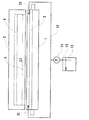
以下、本発明の感光材料処理装置について図面を用いて詳細に説明をする。図1は本発明の一実施様態である感光材料の処理装置の概略断面図である。先ず、スロットダイ2の構造について説明する。6は処理液供給口でマニホールド4と連結されている。該マニホールド4は流入した処理液を幅方向に広げるためのものであり、スロットダイ2の幅方向にわたって設けられている。該マニホールド4で処理液を一旦幅方向に充満させた後、スリット部5に供給する作用を行なう結果、スリット部5からの流出流量を幅方向に均一化させることが可能となる。処理液供給口6は通常スロットダイ2の幅方向の中心に1箇所設けることでよいが、スロットダイ2の幅方向の複数箇所に設けてもよい。マニホールド4の断面形状は、本態様では円形となっているがこれに限らず任意の形状でよい。またマニホールド4の断面積はスロットダイ2の幅方向に亘り一定でなくてもよく、例えば流出する処理液の幅方向の流量均一性をさらに向上せしめるために端部に至るに従って断面積を漸減させてもよい。
Hereinafter, the photosensitive material processing apparatus of the present invention will be described in detail with reference to the drawings. FIG. 1 is a schematic sectional view of a photosensitive material processing apparatus according to one embodiment of the present invention. First, the structure of the slot die 2 will be described.
図1には便宜上図示しないが、スロットダイ2のマニホールド4の塗布幅方向両端部とスリット部5の同両端部は、処理液が流出しないように栓をして用いる。この場合、処理しようとする感光材料の塗布幅に対しスリット部5の幅方向の長さが同じか多少大きくなるように前述の栓を施す。
Although not shown in FIG. 1 for convenience, both ends of the
スロットダイ2の材質は特に限定されるものではないが、処理液に対する耐食性と機械的精度を満足できればよく、例えばステンレス鋼が好ましい。その他にも一般構造鋼にクロムメッキしたものやプラスチック類等が使用可能である。なお、金属で製作する場合は機械加工時の応力歪を排除するため、予め焼鈍処理を施してもよい。 The material of the slot die 2 is not particularly limited as long as the corrosion resistance and mechanical accuracy with respect to the processing liquid can be satisfied. For example, stainless steel is preferable. In addition, chrome-plated general plastics and plastics can be used. In addition, when manufacturing with a metal, in order to exclude the stress distortion at the time of machining, you may anneal beforehand.
図中の10は処理液7を貯留するための処理液貯留タンクである。該処理液貯留タンク10の処理液7をスロットダイ2に供給するための処理液供給手段は、ポンプ8とバルブ9及び配管11により構成される。配管11は貯留タンク10とスロットダイ2の処理液供給口6とを結び、その間に処理液を送液するためのポンプ8と処理液7の送液を停止させるためのバルブ9をそれぞれ配置する。
In the figure,
Pは感光材料で、感光材料搬送手段の1つである感光材料搬送ロール対19により図の左から右方向(矢印PX)に搬送される。13は搬送中の感光材料Pを検出するための検出手段であり、接触式または非接触式の検出器が用いられる。
P is a photosensitive material, which is conveyed from the left to the right (arrow PX) in the figure by a photosensitive material conveying
16は前記処理液供給手段の処理液の供給と停止を制御する処理液供給制御手段である。この処理液供給制御手段16は搬送中の感光材料Pの先頭端部を前記検出手段13で検出することによって、ポンプ8を駆動しバルブ9を開にしてスロットダイ2に処理液7を供給する。また、同様に感光材料Pの終端部を検出手段13で検出することによって、あらかじめ設定された時間が経過した後にポンプ8を停止しバルブ9を閉止する。このような制御をすることで、搬送中の感光材料Pにある一定量の処理液を均一に塗布することができる。
感光材料Pへの塗布量を高い精度で制御する場合は、処理液配管の道中に流量計(図示せず)を配置して該流量計の信号を基準にして前記ポンプ8やバルブ9をフィードバック制御する構成をとることができる。
In the case of controlling the coating amount on the photosensitive material P with high accuracy, a flow meter (not shown) is arranged in the path of the processing liquid piping, and the
処理液のスロットダイ2への供給流量は、所望する処理液の湿潤塗布量と感光材料の塗布幅と感光材料の搬送速度をそれぞれ乗ずることにより決定することができる。 The supply flow rate of the processing liquid to the slot die 2 can be determined by multiplying the desired wet coating amount of the processing liquid, the photosensitive material coating width, and the photosensitive material conveyance speed, respectively.
本発明の特徴である感光材料支持ロール1は、前記スロットダイ2の先端部と対向し離間する位置に配置する。また、感光材料支持ロール1は少なくとも感光材料Pの搬送方向とは逆の方向に回転させるためのモーター等の駆動手段18及び前記感光材料支持ロール1の回転を制御するための回転制御手段17を設ける。
The photosensitive
感光材料支持ロール1は塗布幅方向にはスロットダイ2の塗布幅以上とし、スリット部5の鉛直下方延長線上に感光材料支持ロール1の円中心軸がくるように配置する。感光材料支持ロール1の直径は20mm以上が好ましく更に好ましくは30mm以上とし、上限は50mm程度とする。表面材質は処理液に対する耐食性及び高い真直度を有するものであれば特に制限されず、例えばステンレス鋼、プラスチック類、フッ素系樹脂などを用いることができる。
The photosensitive
しかしながら、前述したように感光材料支持ロール1は前記スロットダイ2の先端部と対向する面が平面ではないため、スロットダイ2先端部と対向する前記支持ロール1との間に処理液が溜まりにくい。また別の問題は特に感光材料の支持体にアルミニウム等の金属板を用いる場合、感光材料に傷が付く。このような場合、感光材料支持ロール1の表面材質は表面張力が高い特性を有する樹脂を用いることが好ましく、特にフッ素系樹脂を用いることがより好ましい。そうすることによって、前記スロットダイ2の先端部と前記感光材料支持ロール1の間に形成される液の溜まりを増大させ、すぐに現像液が流れ落ちるのを防止し、更には感光材料に傷を付けるのを防止することができる。
However, as described above, the surface of the photosensitive
感光材料支持ロール1とスリット部5の先端部(スロットダイ2の先端部)の距離Hは、3mm以内が好ましく、より好ましくは2mm以内で、更に好ましくは1.5mm以内で、特に好ましくは1.0mm以内である。距離Hの下限は、感光材料Pの感光面がスリット部5の先端部(スロットダイ2の先端部)に接触しない距離である。
The distance H between the photosensitive
本発明の処理装置において、感光材料支持ロール1とスリット部5の先端部の距離Hを常に安定させ、低コストで製作できることから、前記感光材料支持ロール1は金属ロールとその表面に巻き付けた筒状のフッ素樹脂から成る感光材料支持ロールを用いることが好ましい。図8は感光材料支持ロール1の構成部材を示した図である。感光材料支持ロール1は、芯になる金属ロール80と、該金属ロール80の表面を覆う筒状のフッ素樹脂81から成る。金属ロール80の材質は処理液に対する耐食性及び高い直線精度維持の目的から、ステンレス鋼が好ましい。また、筒状のフッ素樹脂81は簡易に精度良く製作できることから、金属ロール表面全体を覆うことができる熱によって収縮するタイプを用いることが好ましい。フッ素樹脂81は例えばPTFE、FEP、PFAまたはETFEを使用することができる。フッ素樹脂81の厚みは、0.1mm〜1.0mm程度が好ましい。このように金属ロール80と筒状のフッ素樹脂81を組み合わせることによって感光材料支持ロール1の直線精度を維持しながら、簡易に製作することができる。
In the processing apparatus of the present invention, since the distance H between the photosensitive
本発明における処理液の塗布量は1平方メートル当たり100ミリリットル以下が好ましい。このように塗布量を少なくすると感光材料先端部の均一な処理が難しくなる。特に感光材料支持部材をロールにすることでスリット先端部と対向する前記感光材料支持ロール1との間に処理液が留まりにくい。この問題を解決するために、本発明においては、感光材料Pが前記スロットダイ2の先端部に到達するに先立ち、検出手段13により検出した信号を処理液供給制御手段16と回転制御手段17に送ることによって、あらかじめ処理液供給手段によりスロットダイ2の先端部より処理液7を流出させながら、駆動手段18によって該感光材料支持ロール1を前記感光材料Pの搬送方向(矢印PX)と逆の方向に回転するように制御させる。
The coating amount of the treatment liquid in the present invention is preferably 100 ml or less per square meter. If the coating amount is reduced in this way, uniform processing of the front end portion of the photosensitive material becomes difficult. In particular, when the photosensitive material support member is a roll, the processing liquid is less likely to stay between the photosensitive
上述の様な制御を行うことでスロットダイ2の先端部から塗布幅方向均一に流出された処理液7は、前記スロットダイ2の先端部と感光材料支持ロール1の間で僅かな液膜を形成する。そして感光材料支持ロール1を感光材料の搬送方向と逆の方向に回転させることで、感光材料支持ロール1の搬送方向上流側に積極的に処理液が流れるようになる。このような状態で感光材料を処理すると、感光材料処理先端部が感光材料支持ロール1に接触した時、より多くの処理液を感光材料先端部に供給することができる。そして前記感光材料の先端部がスロットダイ2の先端部に到達すると、連続して処理液7の塗布が行われる。また、感光材料がスロットダイ2の先端部に到達するに先立ち、あらかじめスロットダイ2の先端部より処理液7を流出させる流量は、感光材料Pに処理液7を塗布する時の流量より多い流量にしてもよい。
By performing the control as described above, the
スロットダイ2の先端部からの処理液7の流出開始と感光材料支持ロール1の駆動開始のタイミングは必ずしも同じでなくとも良い。また、感光材料支持ロール1の回転方向は少なくとも感光材料Pがスロットダイ2の位置に到達するまで感光材料の搬送方向と逆の方向に回転させる必要があるが、感光材料Pがスロットダイ2に到達した時点で感光材料支持ロール1を停止させてもよい。感光材料の裏面に対する傷発生等を考慮すると、感光材料Pがスロットダイ2に到達した時点で感光材料支持ロール1を感光材料Pの搬送方向と同方向同速度で回転させるように駆動手段18を制御することが好ましい。
The start timing of the outflow of the
感光材料支持ロール1を搬送方向とは逆の方向に回転させる場合の周速度は、スロットダイ2の先端部と感光材料支持ロール1の間の液膜形成(処理液が溜まる量)に大きく関わるため、少なくとも感光材料の搬送速度より遅くなるように駆動手段18を設定する。一般的に、感光材料Pの搬送速度を10mm/秒〜40mm/秒とした場合、感光材料支持ロール1の周速度は5mm/秒〜30mm/秒とし、好ましくは5mm/秒〜20mm/秒とする。
The peripheral speed when the photosensitive
また、図2に示すようにスロットダイ2の先端の搬送方向平面長さを、スリット5を基準に搬送方向下流側平面と搬送方向上流側平面に分け、該下流側の平面部の長さL2より該上流側の平面部の長さL1を長くすることで、更に感光材料先端部の均一塗布に大きな効果をもたらすことができる。上流側の平面部長さL1を下流側の平面部長さL2より長くすることで、スロットダイ2の先端部から流出した処理液がより広い平面に拡がり、結果としてスリット5より上流側に大きな液膜(処理液が多く留まる)が形成される。下流側の平面部の長さL2は1mm〜3mm程度とし、上流側平面長さL1の長さは3mm〜8mm程度が適当である。
Further, as shown in FIG. 2, the plane length in the conveyance direction at the tip of the slot die 2 is divided into a plane in the conveyance direction and a plane in the conveyance direction on the basis of the
スロットダイ2の先端部の該スリット5を挟んだ両側の先端平面部の感光材料搬送方向における前記下流側の平面部長さL2より前記上流側の平面部の長さL1を長くする方法としては、図2に示すようにスロットダイ2の先端平面部をそれぞれ異なる長さ(厚み)に加工することが好ましい。
As a method of making the length L1 of the upstream plane portion longer than the downstream plane portion length L2 in the photosensitive material transport direction of the tip plane portions on both sides of the
次に、前記感光材料支持ロールに洗浄液を供給するための洗浄液供給手段を備え、前記感光材料支持ロールに供給された洗浄液を拡散するための洗浄液拡散手段を前記感光材料支持ロールに当接配置した感光材料処理装置について説明する。 Next, cleaning liquid supply means for supplying a cleaning liquid to the photosensitive material support roll is provided, and cleaning liquid diffusion means for diffusing the cleaning liquid supplied to the photosensitive material support roll is disposed in contact with the photosensitive material support roll. The photosensitive material processing apparatus will be described.
図1に示すように、感光材料支持ロール1とスロットダイ2の先端を洗浄するための洗浄液12を貯留するための貯留タンク13と、洗浄液12を送液するためのポンプ14と配管15からなる洗浄液供給手段を設け、前記感光材料支持ロール1と平行して、前記感光材料支持ロール1と同等の長さを有する洗浄液拡散手段の洗浄液拡散部材3を前記感光材料支持ロール1に当接配置する。洗浄液拡散手段である洗浄液拡散部材3はロールが好ましく、本実施例ではロールを用いた。
As shown in FIG. 1, the photosensitive
洗浄液拡散部材3は感光材料支持ロール1の水平方向中心軸と同じかやや上方に位置するように配置し、感光材料支持ロール1の搬送方向上流側または下流側のどちらに設けてもよい。またロールからなる前記洗浄液拡散部材3の直径は感光材料支持ロール1に対して0.2〜0.8の比率で5mm〜30mm程度とする。ロールからなる表面材質は処理液に対する耐食性及び高い真円度を有するものであれば特に制限されず、例えばステンレス鋼、プラスチック類、フッ素系樹脂などを用いることができる。またロールからなる前記洗浄液拡散部材3は感光材料支持ロール1の塗布幅方向の全てに渡って接触していることが好ましく、回転または固定させてもよい。
The cleaning
洗浄液12の供給は、感光材料支持ロール1と前記洗浄液拡散部材3とが当接された部分の上部に行うのが好ましい。例えば、図3に示すように洗浄液12が満たされた洗浄液貯留タンク13から洗浄液を送るためのポンプ14を介し配管15を2つに分岐させる。分岐させた配管15はスロットダイ2の塗布幅L3の両側に配置し、それぞれの洗浄液供給口にノズル21、22を設ける。そうすることによって、より少ない洗浄液12を感光材料支持ロール1と洗浄液拡散部材3との当接上部に溜まりを形成しながら塗布幅方向全域に洗浄液を効果的に行き渡らすことができる。洗浄液12の供給は上述したように感光材料支持ロール1と洗浄液拡散部材3とが当接された部分の上部に行う方法であれば特に限定されるものでなく、塗布幅方向均一に洗浄液を流出させるように細工を施したシャワーパイプ等を用いてもよい。
The cleaning
本発明の実施例において洗浄液拡散手段としてロールからなる洗浄液拡散部材3を用いたが、上記の様に塗布幅方向全域に洗浄液12を拡げる手段であれば洗浄液拡散部材3はロールに限定されるものではない。例えば感光材料支持ロール1と同等の長さを有する板状のものを塗布幅方向の全てに渡って感光材料支持ロール1に当接させてもよい。
In the embodiment of the present invention, the cleaning
処理液塗布部(感光材料支持ロール1とスロットダイ2の先端部)の洗浄は通常処理を行わない間または停機時に行うことが好ましい。処理を行わない間または停機時に、スロットダイ2の先端部と対向する感光材料支持ロール1の塗布部に処理液が残留し、空気に触れることで結晶化しやすい。結晶の成長度合いによってはスロットダイ2の先端より供給された処理液自身による洗浄も難しくなる。従って本発明は、処理を行わない間または停機時に洗浄液供給手段であるポンプ14及び配管15を用いてノズル21、22から定期的に洗浄液12を供給する。また、洗浄液12の供給と同時期に感光材料支持ロール1を回転させることが好ましく、結果的にスロットダイ2の先端部及び感光材料支持ロール1の周囲全体に洗浄液12を与え、処理液結晶化防止により大きな効果が得られる。
It is preferable to clean the processing liquid application part (the photosensitive
上記の処理を行わない間または停機時とは、最後に感光材料を処理してから次に感光材料を処理するまでの待機している時期である。ノズル21、22から洗浄液12を流出させるタイミングは、特に限定するものではないが、最後に感光材料を処理してから次に処理するまでの期間において、30分〜3時間に1回の割合で流出させることが好ましい。例えば、感光材料を検出するための検出手段の信号を基に最後に感光材料を処理した時期を記憶させて洗浄液12の供給までの時間を計測することができる。また1回における流出量は3ml〜60mlが好ましく、環境条件及び塗布幅に応じて適宜決定することができる。
The period when the above processing is not performed or when the processing is stopped is the time when the photosensitive material is processed until the next processing of the photosensitive material. The timing at which the cleaning
洗浄時に前記感光材料支持ロール1を駆動するタイミングは、洗浄液12の供給開始と同時であることが好ましく、洗浄時の感光材料支持ロール1の周速度は10mm/秒〜40mm/秒程度とする。また感光材料支持ロール1の駆動開始から駆動停止までの駆動時間は30秒〜3分程度とする。
The timing at which the photosensitive
本発明に用いる洗浄液12は特に限定するものではないが、水道水に少量の界面活性剤や有機溶媒を添加したもの、及び現像液の後に用いられる中和液や水洗水を用いることができる。また、より大きな洗浄効果を得るために、洗浄液12を温調してもよい。
Although the washing | cleaning
本発明の処理装置において、前記スロットダイ2としてコストが低く、簡易的に製作されたスロットダイを用いることが好ましい。以下、簡易的に製作されたスロットダイについて説明する。図4はスロットダイをそれぞれの構成部材に解体した側面図である。マニホールドを形成するための溝44が切り抜かれた平板41と、該平板41を両側から挟み込んで固定する平板42及び43を有する。平板41と平板42または43のどちらか一方との間(図面では平板41と43の間)には、スリットを形成するためのフィルムFを介在する。液体の供給口45は平板42または43のどちらに設けても良いが、前記スリットを形成しない方の平板に設けるのが好ましい。供給口45は、溝44に処理液を供給する。供給口45は2個以上設けても良い。
In the processing apparatus of the present invention, it is preferable to use a slot die that is low in cost and manufactured simply as the slot die 2. Hereinafter, a simply manufactured slot die will be described. FIG. 4 is a side view in which the slot die is disassembled into its constituent members. It has the
図4に示すように、スリットを形成する平板41と43の下端部の長さは同一にし、もう一方の平板42はそれらより短くするのが好ましい。フィルムFの下端部長さについても、平板41及び43と同一にするのが好ましいが、若干長くなることもしくは若干短くなるのは許容される。
As shown in FIG. 4, it is preferable that the lengths of the lower ends of the
平板41と43の間に挿入するフィルムFは、マニホールドと連続したスリットを平板41と43の間に形成するためのものであり、予め設計されたスリットの厚みと同一の厚みのフィルムが用いられる。フィルムの材質としてはポリエチレンテレフタレートまたはポリ塩化ビニルのようなプラスチックフィルムが好ましく、厚みは50〜300μm程度が一般的である。フィルムFは、スロットダイの下方部にスリットを形成するような形状であれば特に限定されない。例えば、図5aに示すように、下端部のみ開放にして、両側端部51a、51bと上端部52を封鎖する形状のフィルムFを用いることができるが、好ましくは図5bに示す形状である。図5bのフィルムFは、図5aと同様に下端部のみを開放にして両側端部51a、51bと上端部52を封鎖するが、更に上端部52に一体的に複数のフラップ53a〜53dを有する。該フラップは、スリット内部に介在(位置)する長さを有する。
The film F inserted between the
図5bに示すフィルムFを平板41に重ね合わせたときの平面図を図6に示す。平板41にはマニホールドを形成する溝44が切り抜きされており、フィルムFの両側端部51a、51bと上端部52が溝44を覆わないように重ね合わされている(但し、本発明に於いては、マニホールドの機能を阻害しない程度に溝44の一部を覆っても差し支えない)。図示しないが、更にこの上に平板43を重ね合わせることによって、斜線で示すスリット60が形成される。このスリット60は、マニホールド(溝44)とつながっており、マニホールドに供給され幅方向に分配された液体は、スリット60を通過することによって更に幅方向に均一な流量となって感光材料等に塗布される。ここで重要なことは、スリット60の厚みを幅方向に均一に保持することであり、この働きをするのがフィルムFのフラップ53a〜53dである。即ち、このフラップをスリット60に挿入し、平板41と43をボルトやネジ等で固定することによって幅方向に均一な厚みのスリットを簡単に形成することができる。図5、図6の符号50はボルトやネジで固定するための穴である。
FIG. 6 shows a plan view when the film F shown in FIG. A
本発明に用いられる簡易スロットダイは、平板41と43の間にフィルムFを介在させるという極めて簡単な組み合わせでスリットを形成するものであるが、塗布幅(スロットダイの幅方向長さ)が長くなるとスリットの厚みが塗布幅方向で振れを生じるようになる。この振れは、フィルムFに一体的に設けられたフラップを適当な間隔でスリット内に介在(位置)させるという簡単な手段で解消することができる。スリット内での均一な流れを確保するためのフラップの形状等については以下に述べる。
The simple slot die used in the present invention forms a slit by a very simple combination of interposing the film F between the
上記したフラップの個数は、塗布幅によって適宜選択されるが、1個であっても充分に効果を奏する。好ましくは、3〜20cmの間隔で設けるのがよい。より好ましくは3〜10cmの間隔で設ける。フラップの幅は5〜20mm程度で固定するためのボルトやネジが挿入できる程度の大きさにするのが好ましく、必要以上に大きくしない方がよい。フラップの形状は先端が細った形状にするのが好ましい。例えば、三角形、山形、半円形等である。このフラップは、マニホールドからスリットへの液体の流れを部分的に一旦中断するが、スリットの先端部(液体が外へ流出する部分)においては幅方向に均一な流れを生じさせることが必要であり、この意味からフラップの形状、個数及び先端部の位置が選択される。とりわけ、フラップの形状及び先端部の位置は重要である。形状は前述したように先細りが好ましく、フラップ先端部の位置はスリット先端部より内側(上方)にする必要がある。フラップ先端部とスリット先端部との距離は、フラップ先端部の形状によって変わってくるが、1mm以上が好ましく、2mm以上がより好ましい。 The number of flaps described above is appropriately selected depending on the coating width, but even if it is one, the effect is sufficiently obtained. Preferably, it is good to provide at intervals of 3 to 20 cm. More preferably, it is provided at intervals of 3 to 10 cm. The width of the flap is preferably about 5 to 20 mm, and is preferably large enough to insert a bolt or screw for fixing, and should not be made larger than necessary. The shape of the flap is preferably a shape with a thin tip. For example, a triangle, a mountain shape, a semicircle, and the like. This flap partially interrupts the flow of liquid from the manifold to the slit, but it is necessary to generate a uniform flow in the width direction at the tip of the slit (portion where the liquid flows out). From this meaning, the shape and number of flaps and the position of the tip are selected. Among other things, the shape of the flap and the position of the tip are important. As described above, the shape is preferably tapered, and the position of the flap tip must be inside (above) the slit tip. The distance between the flap tip and the slit tip varies depending on the shape of the flap tip, but is preferably 1 mm or more, and more preferably 2 mm or more.
図5bのように、フィルムFにフラップ53を一体的に設けた方が、スロットダイを組み立てる上で好ましいが、フィルムFとフラップ53を別体にして、フラップ53を独立させてスリット内部に介在させても良い。この場合のフラップ53の先端部形状及び先端部の位置については、前述の説明に準じる。いずれにしても、フィルムFとフラップ53は同一の厚みである。 As shown in FIG. 5b, it is preferable to assemble the flap 53 integrally with the film F in order to assemble the slot die. However, the film F and the flap 53 are separated and the flap 53 is made independent and interposed in the slit. You may let them. The tip shape of the flap 53 and the position of the tip in this case are the same as described above. In any case, the film F and the flap 53 have the same thickness.
平板41、平板42、平板43の材質はアクリル、ポリカーボネート、塩化ビニル等のプラスチック樹脂やステンレス鋼を用いることができるが、ステンレス鋼が好ましく用いられる。平板41の厚みは、切り抜きされた溝によってマニホールド44の大きさを左右する。本発明に於いて、マニホールド44の断面積(幅方向に直交する断面)は10〜100平方ミリメートルの範囲が好ましく、特に10〜80平方ミリメートルが好ましく、更に10〜50平方ミリメートルの範囲が好ましい。従って、平板41の厚みは1mm〜8mm程度が適当である。また、平板41と平板43でスリットを形成するが、スリットを形成する面は平滑に研磨されている必要がある。平板41及び43は、冷間圧延されたステンレス(2B)で、機械研磨されたNO.4を用いるのが好ましい。平板43の厚みは1mm〜8mmである。平板42は、平板41と43が薄いステンレスを用いた場合の撓み等を抑制するために比較的厚いステンレスが用いられる。平板42の厚みは5〜15mm程度が適当である。
The material of the
マニホールドを形成するための平板41に切り抜きされた溝44の大きさは、断面積については上述した通りであり、平板41の厚みによって鉛直方向(液体が落下する方向)の長さが変わってくるが、溝44の鉛直方向の長さは5〜20mm程度が適当である。また溝44の幅方向長さは、塗布幅によって適宜設定されるが、塗布幅と同程度もしくは若干長い目が好ましい。通常、塗布幅とスリット60の幅方向長さは同程度に設計されるが、上記した溝44の幅方向長さは、スリット60を落下する液体を幅方向に均一に広げるのに充分な長さであれば、塗布幅より短くてもよい。
The size of the
マニホールド(溝44)の断面積はスロットダイの幅方向に亘り一定でなくてもよく、例えば流出する処理液の幅方向の流量均一性をさらに向上せしめるために端部に至るに従って断面積を漸減させてもよい。 The cross-sectional area of the manifold (groove 44) may not be constant along the width direction of the slot die. For example, in order to further improve the flow rate uniformity in the width direction of the outflowing processing liquid, the cross-sectional area is gradually reduced toward the end. You may let them.
本発明の処理装置おいて上述のような簡易的に製作されたスロットダイ2を用いる場合、スロットダイ2の先端部の該スリットフィルムFを挟んだ両側の先端平面部の感光材料搬送方向における前記下流側の平面部長さL2より前記上流側の平面部の長さL1を長くする方法としては、例えば図7(a)に示すようにスリットフィルムFをそれぞれ異なる厚みの平板41及び43で挟み込んでもよい。また、図7(b)のようにスロットダイ2の先端部の前記上流側の平面部の長さが長くなるように、塗布幅方向全域に渡って例えばフィルムまたは樹脂等の上流側平面部延長部材70をスロットダイ2の上流側の平板43の先端部のみに貼り付けてもよい。
In the case of using the slot die 2 that is simply manufactured as described above in the processing apparatus of the present invention, the front end flat portions on both sides of the slit film F at the front end portion of the slot die 2 in the photosensitive material transport direction. As a method of making the length L1 of the upstream plane portion longer than the downstream plane portion length L2, for example, as shown in FIG. 7A, the slit film F may be sandwiched between
本発明者らは、感光材料を搬送する搬送手段と、前記搬送手段により搬送される感光材料に処理液を塗布するためのスロットダイと、処理液貯留タンクと、該処理液貯留タンクの処理液を前記スロットダイに供給するための処理液供給手段と、前記スロットダイの先端部に対向し離間する位置に配置された感光材料支持ロールと、感光材料の検出手段と、前記感光材料支持ロールを少なくとも感光材料の搬送方向とは逆方向に回転させるための駆動手段と、を備えた感光材料処理装置により、感光材料の極先端部及び塗布幅方向における両端部の塗布が不均一となり処理むらが発生しやすいという従来の懸案点を解消できることを見いだした。また、前記感光材料支持ロールに洗浄液を供給するための洗浄液供給手段と前記感光材料支持ロールに洗浄液を拡散するための洗浄液拡散手段を前記感光材料支持ロールに当接配置した感光材料処理装置により、前記感光材料支持ロールとスロットダイの先端部に処理液が多く残留し、固着結晶化しやすという従来の懸案点を解消できることを見いだした。 The present inventors include a conveying means for conveying a photosensitive material, a slot die for applying a processing liquid to the photosensitive material conveyed by the conveying means, a processing liquid storage tank, and a processing liquid in the processing liquid storage tank. A processing solution supply means for supplying the slot die to the slot die, a photosensitive material support roll disposed at a position facing and spaced from the tip of the slot die, a photosensitive material detection means, and the photosensitive material support roll. The photosensitive material processing apparatus having at least a driving means for rotating in the direction opposite to the conveyance direction of the photosensitive material causes uneven coating of the extreme tip of the photosensitive material and both ends in the coating width direction, resulting in uneven processing. I found out that it was possible to eliminate the conventional concern that it was likely to occur. Further, a photosensitive material processing apparatus in which cleaning liquid supply means for supplying a cleaning liquid to the photosensitive material support roll and cleaning liquid diffusion means for diffusing the cleaning liquid to the photosensitive material support roll are arranged in contact with the photosensitive material support roll, It has been found that a large amount of processing solution remains on the photosensitive material supporting roll and the tip of the slot die, and the conventional problem of easy crystallization can be solved.
1 感光材料支持ロール
2 スロットダイ
3 洗浄液拡散部材
5 スリット
12 洗浄液
DESCRIPTION OF
Claims (1)
Conveying means for conveying the photosensitive material, a slot die for applying the processing liquid to the photosensitive material conveyed by the conveying means, a processing liquid storage tank, and supplying the processing liquid in the processing liquid storage tank to the slot die Processing solution supply means, photosensitive material support roll disposed at a position facing and spaced from the tip of the slot die, photosensitive material detection means, and at least the photosensitive material support roll in the photosensitive material transport direction And a driving means for rotating in the opposite direction to the photosensitive material processing apparatus.
Priority Applications (2)
| Application Number | Priority Date | Filing Date | Title |
|---|---|---|---|
| JP2004046110A JP3983742B2 (en) | 2003-02-28 | 2004-02-23 | Photosensitive material processing equipment |
| US11/062,450 US7275879B2 (en) | 2004-02-23 | 2005-02-22 | Processing device of photo-sensitive material |
Applications Claiming Priority (2)
| Application Number | Priority Date | Filing Date | Title |
|---|---|---|---|
| JP2003052136 | 2003-02-28 | ||
| JP2004046110A JP3983742B2 (en) | 2003-02-28 | 2004-02-23 | Photosensitive material processing equipment |
Publications (3)
| Publication Number | Publication Date |
|---|---|
| JP2004280082A JP2004280082A (en) | 2004-10-07 |
| JP2004280082A5 JP2004280082A5 (en) | 2006-11-02 |
| JP3983742B2 true JP3983742B2 (en) | 2007-09-26 |
Family
ID=33301838
Family Applications (1)
| Application Number | Title | Priority Date | Filing Date |
|---|---|---|---|
| JP2004046110A Expired - Fee Related JP3983742B2 (en) | 2003-02-28 | 2004-02-23 | Photosensitive material processing equipment |
Country Status (1)
| Country | Link |
|---|---|
| JP (1) | JP3983742B2 (en) |
Families Citing this family (1)
| Publication number | Priority date | Publication date | Assignee | Title |
|---|---|---|---|---|
| JP6512894B2 (en) * | 2015-03-27 | 2019-05-15 | 株式会社Screenホールディングス | Treatment liquid supply apparatus and control method of treatment liquid supply apparatus |
-
2004
- 2004-02-23 JP JP2004046110A patent/JP3983742B2/en not_active Expired - Fee Related
Also Published As
| Publication number | Publication date |
|---|---|
| JP2004280082A (en) | 2004-10-07 |
Similar Documents
| Publication | Publication Date | Title |
|---|---|---|
| CN111629838B (en) | Coating device and coating system | |
| JP3983742B2 (en) | Photosensitive material processing equipment | |
| US7275879B2 (en) | Processing device of photo-sensitive material | |
| US5839011A (en) | Apparatus for processing photosensitive material | |
| US7819595B2 (en) | Photosensitive material turning member and developing apparatus | |
| JP2928090B2 (en) | Photosensitive material processing equipment | |
| JP2006082059A (en) | Method and apparatus for bar coating | |
| JP3895664B2 (en) | Photosensitive material processing equipment | |
| JP2006154478A (en) | Photosensitive material processor | |
| JP2008136884A (en) | Bar coating device and its method | |
| JP3895660B2 (en) | Photosensitive material processing equipment | |
| JP3707992B2 (en) | Photosensitive material processing method and photosensitive material processing apparatus | |
| JP2005234438A (en) | Method for processing photosensitive material | |
| JP3492863B2 (en) | Photosensitive material processing equipment | |
| JP2002148777A (en) | Slot die and processor for photosensitive material using the same | |
| JP2008136883A (en) | Bar coating device and its method | |
| JP2005275033A (en) | Photosensitive material processor | |
| JP2739616B2 (en) | Photosensitive material processing equipment | |
| JP3672286B2 (en) | Automatic processing machine for silver halide photographic materials | |
| JP2003075972A (en) | Apparatus for processing photosensitive material | |
| JP2004144871A (en) | Photosensitive material processing apparatus | |
| JP3672288B2 (en) | Automatic processing machine for silver halide photographic materials | |
| JPH1062945A (en) | Photosensitive material processing device | |
| JP2003255504A (en) | Apparatus for processing photosensitive material | |
| JP2001305708A (en) | Photosensitive material processing device |
Legal Events
| Date | Code | Title | Description |
|---|---|---|---|
| A521 | Written amendment |
Free format text: JAPANESE INTERMEDIATE CODE: A523 Effective date: 20060920 |
|
| A621 | Written request for application examination |
Free format text: JAPANESE INTERMEDIATE CODE: A621 Effective date: 20060920 |
|
| A977 | Report on retrieval |
Free format text: JAPANESE INTERMEDIATE CODE: A971007 Effective date: 20070606 |
|
| TRDD | Decision of grant or rejection written | ||
| A01 | Written decision to grant a patent or to grant a registration (utility model) |
Free format text: JAPANESE INTERMEDIATE CODE: A01 Effective date: 20070612 |
|
| A61 | First payment of annual fees (during grant procedure) |
Free format text: JAPANESE INTERMEDIATE CODE: A61 Effective date: 20070704 |
|
| FPAY | Renewal fee payment (event date is renewal date of database) |
Free format text: PAYMENT UNTIL: 20100713 Year of fee payment: 3 |
|
| R150 | Certificate of patent or registration of utility model |
Free format text: JAPANESE INTERMEDIATE CODE: R150 |
|
| FPAY | Renewal fee payment (event date is renewal date of database) |
Free format text: PAYMENT UNTIL: 20110713 Year of fee payment: 4 |
|
| FPAY | Renewal fee payment (event date is renewal date of database) |
Free format text: PAYMENT UNTIL: 20110713 Year of fee payment: 4 |
|
| FPAY | Renewal fee payment (event date is renewal date of database) |
Free format text: PAYMENT UNTIL: 20120713 Year of fee payment: 5 |
|
| FPAY | Renewal fee payment (event date is renewal date of database) |
Free format text: PAYMENT UNTIL: 20120713 Year of fee payment: 5 |
|
| FPAY | Renewal fee payment (event date is renewal date of database) |
Free format text: PAYMENT UNTIL: 20130713 Year of fee payment: 6 |
|
| LAPS | Cancellation because of no payment of annual fees |