JP3983303B2 - Electric toaster with asymmetric heating effect - Google Patents
Electric toaster with asymmetric heating effect Download PDFInfo
- Publication number
- JP3983303B2 JP3983303B2 JP52919398A JP52919398A JP3983303B2 JP 3983303 B2 JP3983303 B2 JP 3983303B2 JP 52919398 A JP52919398 A JP 52919398A JP 52919398 A JP52919398 A JP 52919398A JP 3983303 B2 JP3983303 B2 JP 3983303B2
- Authority
- JP
- Japan
- Prior art keywords
- heating element
- sub
- elements
- heating
- electric toaster
- Prior art date
- Legal status (The legal status is an assumption and is not a legal conclusion. Google has not performed a legal analysis and makes no representation as to the accuracy of the status listed.)
- Expired - Lifetime
Links
Images


Classifications
-
- A—HUMAN NECESSITIES
- A47—FURNITURE; DOMESTIC ARTICLES OR APPLIANCES; COFFEE MILLS; SPICE MILLS; SUCTION CLEANERS IN GENERAL
- A47J—KITCHEN EQUIPMENT; COFFEE MILLS; SPICE MILLS; APPARATUS FOR MAKING BEVERAGES
- A47J37/00—Baking; Roasting; Grilling; Frying
- A47J37/06—Roasters; Grills; Sandwich grills
- A47J37/08—Bread-toasters
-
- H—ELECTRICITY
- H05—ELECTRIC TECHNIQUES NOT OTHERWISE PROVIDED FOR
- H05B—ELECTRIC HEATING; ELECTRIC LIGHT SOURCES NOT OTHERWISE PROVIDED FOR; CIRCUIT ARRANGEMENTS FOR ELECTRIC LIGHT SOURCES, IN GENERAL
- H05B1/00—Details of electric heating devices
- H05B1/02—Automatic switching arrangements specially adapted to apparatus ; Control of heating devices
- H05B1/0227—Applications
- H05B1/0252—Domestic applications
- H05B1/0258—For cooking
Abstract
Description
本発明は、第1加熱素子及び第2加熱素子を具え、第1及び第2加熱素子が電気的に直列に接続されて交流電源電圧を印加され、第1加熱素子が二つのサブ素子に分割され、サブ素子が第1ノードで相互接続され、二つのサブ素子のうちの一つを起動及び停止させるためのスイッチ手段を具える電気トースターに関するものである。
このような電気トースターはオーストラリア特許明細書第573097号から既知である。この明細書には、パンの切片の通常の両面焼きの構成から、長方形パン、ローフカットの棒形パン、クランペット、マフィンその他の片面焼きの非対称構成に切替えることのできるトースターが開示されている。この既知の電気トースターは、加熱室の対向面に配置され直列に接続された第1及び第2の主加熱素子を具える。第3の補助加熱素子が第1主加熱素子と直列に配置され、物理的には第1加熱素子と同一の支持体上に配置されている。第3加熱素子と並列の電気スイッチにより、第3加熱素子のオンとオフとを切替えることができる。非対称加熱モードにおいては、電気スイッチが開になり第3加熱素子が動作可能である。第1及び第3加熱素子の組合せで増加する抵抗値に基づいて、この組合せ加熱素子によって第2素子より大きい輻射パワーが発生され、パンの切片の片面が他の面より強く焼かれる。通常モード即ち対称加熱モードにおいては、電気スイッチが閉であり第3加熱素子が短絡され、パンの切片の両面で等しい輻射パワーが発生される。第1及び第3加熱素子は、同一支持体上に加熱導体の交互巻きの巻線から構成されている。隣接巻線間の最小間隔は一定の要求を満たす必要がある。これは、第3加熱素子の巻線の交互巻きのための空間を与えるために、第1加熱素子の巻線間の間隔が最小間隔の2倍でなければならないことを意味する。従って、第1加熱素子の巻線の密度は可能な値より小さい。第2加熱素子が第1加熱素子と同一の加熱導体材料から形成されている場合には、第2加熱素子についても同様である。第1及び第2加熱素子のかなり粗い巻線パターンの結果として、通常モードにおけるパンの切片の輻射は、このような非対称モードを持たない従来のトースターに比較して低下する。
従って、本発明の目的は、通常及び非対称パン焼きモードにおいて改善されたパン焼き性能を有する電気トースターを提供することにある。
この目的のため、本発明によれば、冒頭の文節で述べたような電気トースターにおいて、起動及び停止させるためのスイッチ手段が、直列接続された第1一方向性手段及び第2一方向性手段を具え、それらが第1加熱素子と並列に接続され、第1一方向性手段及び第2一方向性手段が第2ノードで相互接続された対応電極を有し、及び、第1ノード及び第2ノードを相互接続するための手段を具えることを特徴とする。
非対称モードにおいては、第1加熱素子の二つのサブ素子が上述の特許明細書から既知のよう順列になっている。通常モードにおいては、相互接続手段が第1及び第2ノードを接続するように動作する。例えばバックツーバックに接続されたダイオードからなる第1及び第2の一方向性手段が、交流電源電圧の正又は負の半周期の間のみ導通する。この結果、サブ素子が等しい抵抗値を持つ好ましい状態であると仮定すれば、二つのサブ素子の各々がパワーの半分ずつを供給する。通常モードでは両サブ素子が動作するので、それらが一つの支持体上に隣接して配置され、全輻射面の上部及び下部(又は左側及び右側)半分を形成することができる。加熱導体の交互巻きはもはや必要ではなく、二つのサブ素子の各々の巻線間の間隔を、均一な輻射を得るために必要な最小値に設定することができる。通常加熱モードにおける動作加熱導体の数の増加により、一層の均一パン焼き効果が得られる。
一つの実施例においては、第1加熱素子の二つのサブ素子が支持体上の加熱導体の巻線からなり、二つのサブ素子の個々の巻線が支持体の隣接した部分に位置し、第2加熱素子が他の支持体上の加熱導体の巻線からなり、第2加熱素子の巻き数が、第1加熱素子の二つのサブ素子の巻き数の和に実質的に等しい。
このような構成によれば、通常モードにおいて、パンの切片の両面を良好に均一に焼くことができる。
第1ノードと第2ノードとを相互接続する手段は、ユーザーが操作可能な電気スイッチ、リレー又はトライアックのような制御可能電子スイッチとすることができる。トライアックの場合、トライアックのオンオフデューティサイクルを適当に制御することにより、通常から非対称パン焼きへ連続的に調整することができる。
他の実施例においては、第1ノードと第2ノードとを相互接続する手段は単純な短絡回路であり、第1及び第2一方向性手段がサイリスタであり、サイリスタがコントローラからトリガーパルスを受信する。
必要な場合、他の即ち第2の加熱素子も二つのサブ素子に分割し、一方向性素子及び相互接続手段を具えることができる。これにより、ユーザーが、パンの切片のいずれの面を強く焼くかを選択することができる。この配置は、両加熱素子を同一の抵抗値を持つ加熱導体から形成することができるという他の利点を有する。上述の配置とは逆の場合、第1加熱素子が二つのサブ素子からなり、各々がN回の巻線を有し且つ各々が抵抗値Rを有し、第2加熱素子が2N回の巻線を有し且つ抵抗値Rを有する。後者の場合、第1加熱素子の二つのサブ素子に用いる導体の比抵抗は、第2加熱素子に用いる導体の比抵抗より大きくなければならない。
2枚のパンの切片を同時に焼くための二つの加熱室を有するトースターにおいては、サブ素子に分割された第1加熱素子の他の端部に他の第2加熱素子を直列に接続して二つの外側加熱素子を形成し、更に切替え可能の中央加熱素子を形成するとよい。同様に、サブ素子を二つの加熱室の外側に配置し、第2加熱素子を中央に配置してもよい。
本発明の上記及び他の特徴及び利点は、図面を用いて行われる以下の本発明の例示的実施例の説明により明らかにされる。
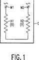
図1は非対称パン焼き機能を具えていない従来のトースターの回路図、
図2は非対称パン焼き機能を具えている第1の従来のトースターの回路図、
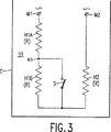
図3は非対称パン焼き機能を具えている第2の従来のトースターの回路図、
図4は図3のトースターの加熱素子の巻線パターンの配置を示す図、
図5は本発明による非対称パン焼き機能を具えているトースターの第1実施例の回路図、
図6は図5のトースターの加熱素子の巻線パターンの配置を示す図、
図7は本発明による非対称パン焼き機能を具えているトースターの第2実施例の回路図、
図8は本発明による非対称パン焼き機能を具えているトースターの第3実施例の回路図、
図9は本発明による非対称パン焼き機能を具えているトースターの第4実施例の回路図、
図10は本発明による非対称パン焼き機能を具えているトースターの第5実施例の回路図、及び
図11は本発明による非対称パン焼き機能を具えているトースターの第6実施例の回路図である。
図1は非対称パン焼き機能を具えていない従来のトースターの回路図である。
このトースターは、加熱室Cの両側に位置する二つの加熱素子H1及びH2を有する。パンの切片又は他の食品が二つの加熱素子H1とH2との間に挿入され、両面が焼かれる。二つの加熱素子H1及びH2は、例えば幹線電圧220VACの交流電圧が供給される端子M1とM2との間に直列に接続される。各加熱素子は抵抗値Rを有し、従って端子M1及びM2で見える全抵抗値は2Rである。この従来のトースターは、片面に焼かない堅い皮がある長方形パン、ローフカットの棒形パン、クランペット、マフィンその他の片面焼きには適していない。
図2は並列に接続された二つの加熱素子H1及びH2を有する従来のトースターの回路図である。加熱素子H1は、加熱素子H1に直列のスイッチSによりオフにすることができる。図1の構成と同様に各素子の加熱パワーを同一に保持するためには、各加熱素子が抵抗値4Rを持たなければならない。このような高い抵抗値では加熱素子の導体が極めて傷つき易いので、問題を引き起こす可能性がある抵抗値2Rは良い選択であるが、この場合は、トライアック制御によって実効幹線電圧を低くする必要がある。この解は有効であるが高価である。
低価格の解が図3に示されている。片面パン焼きは、一つの加熱素子の抵抗値を、例えば加熱素子H1の抵抗値を、他の加熱素子H2の抵抗値に比較して増すことによって得られる。この目的のため、加熱素子は二つのサブ素子H1A及びH1Bに分割される。サブ素子H1BはスイッチSで短絡することができる。二つのサブ素子H1A及びH1B並びに加熱素子H2が、端子M1とM2との間に直列に接続される。サブ素子H1Aの抵抗値及び加熱素子H2の抵抗値は、共にRに等しい。サブ素子H1Bの抵抗値は、例えば同様にRに等しくすることができるが、他の抵抗値を選択することもできる。スイッチSが閉じている時は、トースターは図1に示された構成と同様に通常の二面パン焼きモードで動作する。スイッチSが開いている時は、二つのサブ素子H1A及びH1Bにより相対的に多くの熱が輻射される。サブ素子及び素子H2の抵抗値が等しい場合は、一面では二つのサブ素子によって2/3のパワーが輻射され、他の面では素子H2によって1/3のパワーが輻射される。これは厳密には片面パン焼きではないが、実用上は同一の効果を有する。
図4に示すように、二つのサブ素子H1A及びH1Bは各々支持体SP1上の加熱導体の巻線からなっている。二つの巻線は支持体SP1上で同一の面積を占める必要があるため、交互巻き(インターリーブ)になっている。隣接する巻線間の最小間隔は一定の要求を満たす必要がある。これは、サブ素子H1Bの巻線の交互巻きのための空間を与えるために、加熱サブ素子H1Aの巻線間の間隔が最小間隔の2倍でなければならないことを意味する。従って、サブ素子H1Aの巻線の密度は可能な値より小さい。支持体SP2上の加熱素子H2がサブ素子H1Aと同一の加熱導体材料から作られている場合は、同様のことがこの加熱素子H2についても当てはまる。加熱サブ素子H1A及び加熱素子H2の巻線パターンがかなり粗いため、通常モードにおけるパン切片への輻射が、このような非対称モードを持っていない従来のトースターと比較して低下する。
図5は本発明による非対称パン焼き機能を有するトースターの回路図である。二つのサブ素子H1A及びH1B並びに加熱素子H2が上述の場合と同様に端子M1とM2との間に直列に接続されている。二つのダイオードD1及びD2の直列配置が、二つのサブ素子H1A及びH1Bの直列配置と並列に接続される。これらのダイオードは、ノードN2で、バックツーバックに即ちアノードとアノード又はカソードとカソードが相互接続される。例示としてダイオードが図示されている。例えばダイオード接続トランジスタ等の他の一方向性素子も同様に使用することができる。スイッチSがノードN2と二つのサブ素子H1A及びH1Bの相互接続ノードN1との間に配置される。サブ素子H1A及びH1Bと加熱素子H2との抵抗値は、同一でRに等しいことが望ましい。スイッチSが開いている時はトースターは非対称モードであり図3に関して説明したように動作する。即ち、一面でパワーの2/3が二つのサブ素子H1A及びH1Bによって輻射され、他の面で1/3が素子H2によって輻射される。スイッチSが閉じている時は、トースターは通常パン焼きモードで動作する。ダイオードD1はAC幹線電圧の負の半波間に導通し、電流はサブ素子H1Bを通してのみ流れる。ダイオードD2はAC幹線電圧の正の半波間に導通し、電流はサブ素子H1Aを通してのみ流れる。端子M1とM2との間で見た抵抗値は2Rに等しく、加熱サブ素子H1A及びH1Bが合わせて加熱素子H2と同一のパワーを輻射する。
図6に示されるように、サブ素子H1A及びH1Bの巻線は交互巻き(インターリーブ)ではないが、支持体SP1の隣接した部分に配置される。サブ素子H1Aの巻線の巻き数及びサブ素子H1Bの巻線の巻き数は、素子H2の巻線の巻き数の半分である。この方法においては、加熱導体の巻線の分布を、パン焼きされる切片の両面について等しくすることができ、巻線間の間隔を実用上容易な程度に小さくすることができる。この方法においては、均一なパン焼き効果が両面で得られる。
サブ素子H1A及びH1Bの抵抗値は加熱素子H2の抵抗値と等しいが、それらの巻き数は加熱素子H2の巻き数の半分であるため、サブ素子に用いられる導体の比抵抗は素子H2に用いられる導体のそれより2倍大きい。この比抵抗の相違が好ましくない場合は、素子H2も同様に二つのサブ素子に分割することができ、更に二つのダイオード及び他のスイッチを具えることができる。この場合、4個全てのサブ素子が同一の比抵抗を有する。他のスイッチは、パン焼きする切片の面を選択するためのオプションを提供する。しかしながら、他のスイッチは削除して永久的な接続で置き換えることもできる。
第1ノードと第2ノードとの間のスイッチは、ユーザーが操作できる電気スイッチ、リレー、又は、例えば図7に示すようにコントローラCMによってオンオフデューティサイクルが変化するように駆動されるトライアックのような制御可能の電子スイッチとすることができる。トライアックの場合、トライアックのオンオフデューティサイクルを適当に制御することにより、トースターを通常パン焼きから非対称パン焼きへ連続的に調整することができる。
図8は図5及び7に示された回路に代わる回路を示す図である。ノードN1及びノードN2が直接接続され、ダイオードD1及びD2がサイリスタT1及びT2で置き換えられている。サイリスタT1及びT2のトリガーゲートがコントローラCM2からトリガーパルスを受信する。両サイリスタに対する連続的なトリガーにより、AC幹線電圧の対応する半波の始期における効果は、図5のスイッチSが閉じた時の回路と同一である。即ち、トースターは通常加熱モードで動作する。非対称パン焼き効果は、サイリスタのトリガーを停止することによって得られる。オンオフ比を変えることにより、例えば幹線電圧の連続するサイクルの間トリガーパルスを削除すること(サイリスタのマルチサイクル制御)により、パン焼き効果を非対称から通常へ連続的に変えることができる。
図9は、2枚のパンの切片を同時に焼くための二つの加熱室C1及びC2を有するトースターを示す図であり、分割された第1加熱素子の他の端部に、即ち、端子M1とサブ素子H1Aとの間に、他の第2加熱素子H3が直列に接続され、これにより、二つの外側加熱素子及びスイッチ可能の中央加熱素子が形成されている。
図10は、二つの加熱室C1及びC2を有するトースターの他の構成を示す図である。スイッチ可能のサブ素子H1A及びH1Bが、ここでは加熱室C1及びC2の外側に配置され、第2加熱素子H2及び他の第2加熱素子H3が中央に配置されている。素子H2及びH3の巻線は、一つの支持体上に交互巻きしてもよいし、個別の支持体上に収容してもよい。
図11は、二つの加熱室C1及びC2を有するトースターの第2の他の構成を示す図である。スイッチ可能のサブ素子H1A及びH1Bが、加熱室C2の外側に配置されている。この配置により、二つの加熱室を有するトースターで1枚のパンの切片の両面焼きが可能になる。パンの1枚の切片のみを一つの加熱室に入れる場合、切片の内側の面が外側の面より早く焼ける。これは、空いている加熱室における外側素子からの輻射が中央の素子を加熱するという事実による。この効果を相殺するように、スイッチ可能のサブ素子H1A及びH1Bの配置を用いる。
上述の本発明の実施例は説明のために用いられたものであり、限定する意味を持つものではない。図示されているように、当業者により、これらの実施例に対して、添付の請求項に記載されている本発明の範囲を逸脱することなく種々の変更を行うことができる。The present invention includes a first heating element and a second heating element, wherein the first and second heating elements are electrically connected in series and applied with an AC power supply voltage, and the first heating element is divided into two sub-elements. And an electric toaster comprising switch means for interconnecting the sub-elements at a first node and activating and deactivating one of the two sub-elements.
Such an electric toaster is known from Australian patent specification 573097. This specification discloses a toaster that can be switched from a normal double-sided configuration of bread slices to a rectangular pan, a loaf-cut bar-shaped pan, a crampet, a muffin or other asymmetrical configuration of single-sided baking. . This known electric toaster comprises first and second main heating elements which are arranged on opposite faces of the heating chamber and connected in series. A third auxiliary heating element is arranged in series with the first main heating element and physically arranged on the same support as the first heating element. An electrical switch in parallel with the third heating element can switch the third heating element on and off. In the asymmetric heating mode, the electrical switch is opened and the third heating element is operable. Based on the resistance value that increases with the combination of the first and third heating elements, this combined heating element generates a radiant power that is greater than the second element, causing one side of the bread slice to be baked more strongly than the other side. In the normal or symmetrical heating mode, the electrical switch is closed, the third heating element is shorted, and equal radiation power is generated on both sides of the bread slice. The first and third heating elements are composed of alternating windings of heating conductors on the same support. The minimum spacing between adjacent windings must meet certain requirements. This means that the spacing between the windings of the first heating element must be twice the minimum spacing in order to provide space for alternating windings of the third heating element. Therefore, the winding density of the first heating element is less than possible. The same applies to the second heating element when the second heating element is made of the same heating conductor material as the first heating element. As a result of the rather coarse winding pattern of the first and second heating elements, the radiation of the bread slice in the normal mode is reduced compared to a conventional toaster without such an asymmetric mode.
Accordingly, it is an object of the present invention to provide an electric toaster having improved baking performance in normal and asymmetric baking modes.
To this end, according to the present invention, in the electric toaster as described in the opening paragraph, the switch means for starting and stopping are connected in series with a first unidirectional means and a second unidirectional means. They have corresponding electrodes connected in parallel with the first heating element, the first unidirectional means and the second unidirectional means interconnected at the second node, and the first node and the first Characterized in that it comprises means for interconnecting the two nodes.
In the asymmetric mode, the two sub-elements of the first heating element are permuted as is known from the above-mentioned patent specification. In the normal mode, the interconnection means operates to connect the first and second nodes. For example, first and second unidirectional means comprising diodes connected back-to-back are conducted only during the positive or negative half-cycle of the AC power supply voltage. As a result, assuming that the sub-elements are in a preferred state with equal resistance values, each of the two sub-elements supplies half of the power. Since both sub-elements operate in normal mode, they can be placed adjacent to each other on one support to form the upper and lower (or left and right) halves of the entire radiation surface. Alternate turns of the heating conductor are no longer necessary, and the spacing between the windings of each of the two sub-elements can be set to the minimum required to obtain uniform radiation. By increasing the number of operating heating conductors in the normal heating mode, a more uniform baking effect can be obtained.
In one embodiment, the two sub-elements of the first heating element comprise heating conductor windings on the support, the individual windings of the two sub-elements being located in adjacent portions of the support, The two heating elements comprise windings of the heating conductor on the other support, and the number of turns of the second heating element is substantially equal to the sum of the number of turns of the two sub-elements of the first heating element.
According to such a configuration, both sides of a slice of bread can be baked satisfactorily and uniformly in the normal mode.
The means for interconnecting the first node and the second node may be a controllable electronic switch such as an electric switch, relay or triac operable by the user. In the case of a triac, it is possible to continuously adjust from normal to asymmetric baking by appropriately controlling the on / off duty cycle of the triac.
In another embodiment, the means for interconnecting the first and second nodes is a simple short circuit, the first and second unidirectional means are thyristors, and the thyristor receives a trigger pulse from the controller. To do.
If necessary, the other or second heating element can also be divided into two sub-elements, comprising unidirectional elements and interconnecting means. This allows the user to select which side of the bread slice to bake strongly. This arrangement has the further advantage that both heating elements can be formed from heating conductors having the same resistance value. In the opposite case, the first heating element comprises two sub-elements, each having N windings and each having a resistance value R, and the second heating element having 2N windings. And has a resistance value R. In the latter case, the specific resistance of the conductor used for the two sub-elements of the first heating element must be greater than the specific resistance of the conductor used for the second heating element.
In a toaster having two heating chambers for baking two slices of bread simultaneously, another second heating element is connected in series to the other end of the first heating element divided into sub-elements. One outer heating element may be formed, and a switchable central heating element may be formed. Similarly, the sub element may be disposed outside the two heating chambers, and the second heating element may be disposed in the center.
These and other features and advantages of the present invention will become apparent from the following description of exemplary embodiments of the invention made with reference to the drawings.
FIG. 1 is a circuit diagram of a conventional toaster that does not have an asymmetric baking function.
FIG. 2 is a circuit diagram of a first conventional toaster having an asymmetric baking function,
FIG. 3 is a circuit diagram of a second conventional toaster having an asymmetric baking function,
FIG. 4 is a diagram showing an arrangement of winding patterns of the heating elements of the toaster of FIG.
FIG. 5 is a circuit diagram of a first embodiment of a toaster having an asymmetric baking function according to the present invention,
6 is a view showing the arrangement of winding patterns of the heating elements of the toaster of FIG.
FIG. 7 is a circuit diagram of a second embodiment of the toaster having an asymmetric baking function according to the present invention,
FIG. 8 is a circuit diagram of a third embodiment of the toaster having an asymmetric baking function according to the present invention.
FIG. 9 is a circuit diagram of a fourth embodiment of a toaster having an asymmetric baking function according to the present invention.
FIG. 10 is a circuit diagram of a fifth embodiment of the toaster having an asymmetric baking function according to the present invention, and FIG. 11 is a circuit diagram of a sixth embodiment of the toaster having an asymmetric baking function according to the present invention.
FIG. 1 is a circuit diagram of a conventional toaster that does not have an asymmetric baking function.
The toaster has two heating elements H1 and H2 located on both sides of the heating chamber C. A slice of bread or other food is inserted between the two heating elements H1 and H2, and both sides are baked. The two heating elements H1 and H2 are connected in series between terminals M1 and M2 to which an AC voltage of, for example, a main line voltage of 220 VAC is supplied. Each heating element has a resistance value R, so the total resistance value visible at terminals M1 and M2 is 2R. This conventional toaster is not suitable for rectangular bread with hard skin that does not bake on one side, loaf-cut bar bread, crampets, muffins and other single-sided bake.
FIG. 2 is a circuit diagram of a conventional toaster having two heating elements H1 and H2 connected in parallel. The heating element H1 can be turned off by a switch S in series with the heating element H1. In order to keep the heating power of each element the same as in the configuration of FIG. 1, each heating element must have a
A low cost solution is shown in FIG. Single-sided baking is obtained by increasing the resistance value of one heating element, for example, the resistance value of the heating element H1 compared to the resistance value of the other heating element H2. For this purpose, the heating element is divided into two sub-elements H1A and H1B. The sub element H1B can be short-circuited by the switch S. Two sub-elements H1A and H1B and a heating element H2 are connected in series between the terminals M1 and M2. The resistance value of the sub-element H1A and the resistance value of the heating element H2 are both equal to R. The resistance value of the sub-element H1B can be made equal to R, for example, but other resistance values can be selected. When the switch S is closed, the toaster operates in the normal two-sided baking mode, similar to the configuration shown in FIG. When the switch S is open, a relatively large amount of heat is radiated by the two sub-elements H1A and H1B. When the resistance values of the sub-element and the element H2 are equal, 2/3 power is radiated by the two sub-elements on one side, and 1/3 power is radiated by the element H2 on the other side. Strictly speaking, this is not single-sided baking, but practically has the same effect.
As shown in FIG. 4, the two sub-elements H1A and H1B are each composed of a winding of a heating conductor on the support SP1. Since the two windings need to occupy the same area on the support SP1, they are alternately wound (interleaved). The minimum spacing between adjacent windings must meet certain requirements. This means that the spacing between the windings of the heating sub-element H1A must be twice the minimum spacing to provide space for alternating windings of the sub-element H1B. Therefore, the winding density of the sub-element H1A is smaller than a possible value. The same applies to the heating element H2 if the heating element H2 on the support SP2 is made of the same heating conductor material as the sub-element H1A. Since the winding patterns of the heating sub-element H1A and the heating element H2 are considerably coarse, the radiation to the bread slice in the normal mode is reduced as compared with a conventional toaster that does not have such an asymmetric mode.
FIG. 5 is a circuit diagram of a toaster having an asymmetric baking function according to the present invention. The two sub-elements H1A and H1B and the heating element H2 are connected in series between the terminals M1 and M2 as in the case described above. A series arrangement of two diodes D1 and D2 is connected in parallel with a series arrangement of two sub-elements H1A and H1B. These diodes are interconnected back to back, ie anode and anode or cathode and cathode, at node N2. A diode is illustrated as an example. Other unidirectional elements such as diode-connected transistors can be used as well. A switch S is arranged between the node N2 and the interconnection node N1 of the two subelements H1A and H1B. The resistance values of the sub-elements H1A and H1B and the heating element H2 are preferably the same and equal to R. When switch S is open, the toaster is in an asymmetric mode and operates as described with respect to FIG. That is, 2/3 of the power is radiated by the two sub-elements H1A and H1B on one side, and 1/3 is radiated by the element H2 on the other side. When the switch S is closed, the toaster normally operates in the baking mode. Diode D1 conducts during the negative half-wave of the AC mains voltage, and current flows only through sub-element H1B. Diode D2 conducts during the positive half-wave of the AC mains voltage, and current flows only through sub-element H1A. The resistance value seen between the terminals M1 and M2 is equal to 2R, and the heating sub-elements H1A and H1B together radiate the same power as the heating element H2.
As shown in FIG. 6, the windings of the sub-elements H1A and H1B are not alternately wound (interleaved), but are arranged in adjacent portions of the support SP1. The number of turns of the winding of the sub-element H1A and the number of turns of the winding of the sub-element H1B are half of the number of turns of the winding of the element H2. In this method, the distribution of the windings of the heating conductor can be made equal on both sides of the slice to be baked, and the interval between the windings can be made as small as practical. In this method, a uniform baking effect can be obtained on both sides.
The resistance values of the sub-elements H1A and H1B are equal to the resistance value of the heating element H2, but since the number of turns is half that of the heating element H2, the specific resistance of the conductor used for the sub-element is used for the element H2. Two times larger than that of the conductor to be produced. If this difference in resistivity is not desirable, the element H2 can be similarly divided into two sub-elements, and can further comprise two diodes and other switches. In this case, all four sub-elements have the same specific resistance. Other switches provide an option to select the face of the section to be baked. However, other switches can be deleted and replaced with permanent connections.
The switch between the first node and the second node can be a user operated electric switch, a relay, or a triac, for example, driven by the controller CM to change the on-off duty cycle as shown in FIG. It can be a controllable electronic switch. In the case of a triac, the toaster can be continuously adjusted from normal baking to asymmetric baking by appropriately controlling the on / off duty cycle of the triac.
FIG. 8 is a circuit diagram showing an alternative to the circuit shown in FIGS. Nodes N1 and N2 are directly connected, and diodes D1 and D2 are replaced by thyristors T1 and T2. The trigger gates of thyristors T1 and T2 receive the trigger pulse from the controller CM2. Due to the continuous trigger for both thyristors, the effect at the beginning of the corresponding half-wave of the AC mains voltage is the same as the circuit when the switch S in FIG. 5 is closed. That is, the toaster operates in the normal heating mode. The asymmetric baking effect is obtained by stopping the trigger of the thyristor. By changing the on / off ratio, the baking effect can be continuously changed from asymmetric to normal, for example by eliminating the trigger pulse during successive cycles of the mains voltage (multi-cycle control of the thyristor).
FIG. 9 shows a toaster having two heating chambers C1 and C2 for baking two slices of bread at the same time, at the other end of the divided first heating element, ie with terminals M1 and Another second heating element H3 is connected in series with the sub-element H1A, thereby forming two outer heating elements and a switchable central heating element.
FIG. 10 is a diagram showing another configuration of the toaster having two heating chambers C1 and C2. The switchable sub-elements H1A and H1B are here arranged outside the heating chambers C1 and C2, and the second heating element H2 and the other second heating element H3 are arranged in the center. The windings of the elements H2 and H3 may be alternately wound on one support or may be accommodated on separate supports.
FIG. 11 is a diagram showing a second other configuration of the toaster having two heating chambers C1 and C2. Switchable sub-elements H1A and H1B are arranged outside the heating chamber C2. This arrangement makes it possible to bake a single piece of bread on a toaster with two heating chambers. If only one piece of bread is placed in one heating chamber, the inner surface of the piece is baked faster than the outer surface. This is due to the fact that the radiation from the outer element in the empty heating chamber heats the central element. An arrangement of switchable sub-elements H1A and H1B is used to offset this effect.
The above-described embodiments of the present invention have been used for illustrative purposes and are not meant to be limiting. As shown, various changes may be made by those skilled in the art to these embodiments without departing from the scope of the invention as set forth in the appended claims.
Claims (9)
Applications Claiming Priority (3)
| Application Number | Priority Date | Filing Date | Title |
|---|---|---|---|
| EP97200230.7 | 1997-01-29 | ||
| EP97200230 | 1997-01-29 | ||
| PCT/IB1998/000058 WO1998032361A1 (en) | 1997-01-29 | 1998-01-15 | Electric toaster with asymmetric heating effect |
Publications (3)
| Publication Number | Publication Date |
|---|---|
| JP2000508758A JP2000508758A (en) | 2000-07-11 |
| JP2000508758A5 JP2000508758A5 (en) | 2005-09-08 |
| JP3983303B2 true JP3983303B2 (en) | 2007-09-26 |
Family
ID=8227958
Family Applications (1)
| Application Number | Title | Priority Date | Filing Date |
|---|---|---|---|
| JP52919398A Expired - Lifetime JP3983303B2 (en) | 1997-01-29 | 1998-01-15 | Electric toaster with asymmetric heating effect |
Country Status (6)
| Country | Link |
|---|---|
| US (1) | US6051818A (en) |
| EP (1) | EP0920274B1 (en) |
| JP (1) | JP3983303B2 (en) |
| AT (1) | ATE212203T1 (en) |
| DE (1) | DE69803540T2 (en) |
| WO (1) | WO1998032361A1 (en) |
Families Citing this family (9)
| Publication number | Priority date | Publication date | Assignee | Title |
|---|---|---|---|---|
| KR100626401B1 (en) * | 2002-09-03 | 2006-09-20 | 엘지전자 주식회사 | Circuit for controlling heater in microwave oven having toaster |
| AU2009202799A1 (en) * | 2008-07-11 | 2010-01-28 | Breville Pty Limited | Toaster Oven |
| US20140318382A1 (en) * | 2010-05-11 | 2014-10-30 | Standex International Corporation | Quick heating quartz toaster |
| EP3019061B1 (en) | 2013-07-09 | 2019-09-25 | Strix Limited | Apparatus for heating food |
| EP2873925B1 (en) * | 2013-11-15 | 2021-07-14 | Electrolux Appliances Aktiebolag | Arrangement to supply a resistive load of a household appliance and method for feeding a resistive load of a household appliance |
| GB201500342D0 (en) | 2015-01-09 | 2015-02-25 | Strix Ltd | Apparatus for heating food |
| NZ746496A (en) * | 2016-03-09 | 2021-12-24 | Dmp Entpr Pty Ltd | Conveyor-type oven |
| US10368693B2 (en) | 2017-02-24 | 2019-08-06 | Willard Branch | Food toasting device |
| CN215305176U (en) * | 2021-06-15 | 2021-12-28 | 江门市新会恒隆家居创新用品有限公司 | Toaster |
Family Cites Families (16)
| Publication number | Priority date | Publication date | Assignee | Title |
|---|---|---|---|---|
| US2705276A (en) * | 1954-07-30 | 1955-03-29 | Gen Electric | Heating device control circuit |
| US3247358A (en) * | 1962-09-04 | 1966-04-19 | Norman L Chalfin | Dual heat level soldering iron |
| US3681569A (en) * | 1967-12-22 | 1972-08-01 | Hercules Galion Prod Inc | Heat control system |
| US3692975A (en) * | 1971-03-26 | 1972-09-19 | Joseph Markus | Food preparing system for passenger carrying conveyances |
| US4085309A (en) * | 1975-06-04 | 1978-04-18 | Sperry Rand Corporation | Control circuit arrangement for a portable electrically heated hair treatment appliance |
| US4296312A (en) * | 1979-06-01 | 1981-10-20 | General Electric Company | Electronic temperature sensing system for toaster appliances |
| US4487115A (en) * | 1983-07-13 | 1984-12-11 | Su Cheng Hsiung | Toaster |
| US4538049A (en) * | 1984-04-03 | 1985-08-27 | Black & Decker, Inc. | Toaster oven |
| FR2648034B1 (en) * | 1989-06-09 | 1994-07-08 | Seb Sa | MULTIPURPOSE TOASTER |
| US5218185A (en) * | 1989-08-15 | 1993-06-08 | Trustees Of The Thomas A. D. Gross 1988 Revocable Trust | Elimination of potentially harmful electrical and magnetic fields from electric blankets and other electrical appliances |
| ES2020837A6 (en) * | 1990-01-31 | 1991-10-01 | Agrupada Invest Off | Improvements in household toasters. |
| US5094154A (en) * | 1990-08-27 | 1992-03-10 | Black & Decker Inc. | Electric toaster with time delay mechanism |
| DE4446796C2 (en) * | 1994-12-24 | 1998-01-29 | Rowenta Werke Gmbh | Circuit arrangement for an electric toaster, fed by a mains voltage |
| US5698123A (en) * | 1996-01-16 | 1997-12-16 | Black & Decker Inc. | Toaster compensation for repeated use |
| US5844207A (en) * | 1996-05-03 | 1998-12-01 | Sunbeam Products, Inc. | Control for an electric heating device for providing consistent heating results |
| US5705791A (en) * | 1996-12-20 | 1998-01-06 | Whirlpool Corporation | Automatic toaster and a control therefor |
-
1998
- 1998-01-15 DE DE69803540T patent/DE69803540T2/en not_active Expired - Fee Related
- 1998-01-15 JP JP52919398A patent/JP3983303B2/en not_active Expired - Lifetime
- 1998-01-15 EP EP98900119A patent/EP0920274B1/en not_active Expired - Lifetime
- 1998-01-15 WO PCT/IB1998/000058 patent/WO1998032361A1/en active IP Right Grant
- 1998-01-15 AT AT98900119T patent/ATE212203T1/en not_active IP Right Cessation
- 1998-01-27 US US09/014,171 patent/US6051818A/en not_active Expired - Fee Related
Also Published As
| Publication number | Publication date |
|---|---|
| ATE212203T1 (en) | 2002-02-15 |
| DE69803540D1 (en) | 2002-03-14 |
| EP0920274B1 (en) | 2002-01-23 |
| EP0920274A1 (en) | 1999-06-09 |
| DE69803540T2 (en) | 2002-09-05 |
| WO1998032361A1 (en) | 1998-07-30 |
| JP2000508758A (en) | 2000-07-11 |
| US6051818A (en) | 2000-04-18 |
Similar Documents
| Publication | Publication Date | Title |
|---|---|---|
| US4198553A (en) | Combination oven fully utilizing the capability of a limited power source | |
| CA1253598A (en) | Power control arrangement | |
| CN112205072B (en) | Heating element for a cooking appliance | |
| JP3983303B2 (en) | Electric toaster with asymmetric heating effect | |
| US6455823B1 (en) | Electrical heater with thermistor | |
| US4188520A (en) | Effective concurrent microwave heating and electrical resistance heating in a countertop microwave oven | |
| DE2922003A1 (en) | MICROWAVE OVEN | |
| GB2312570A (en) | Power control for a radiant electric heater | |
| CA2018578C (en) | Multifunction toaster | |
| GB2329769A (en) | Electric heater control | |
| EP0331369A1 (en) | Controllable electric heater | |
| US2084881A (en) | Electric toaster | |
| AU2020282364A1 (en) | Supplementary radiant heat for pellet cooking appliances | |
| WO2004019726A1 (en) | Hair dryer with improved heating power control and circuits therefor | |
| JPH0350421A (en) | Heating structure in heating and cooking device | |
| JPH10106725A (en) | Sheet-like heater element and electric carpet | |
| GB2531599A (en) | Energy saving electric toaster | |
| US1432491A (en) | Electric heater | |
| JPH02270293A (en) | Induction heat cooking appliance | |
| JPH02114488A (en) | Induction heating cooker | |
| JP2702612B2 (en) | Variable output positive temperature coefficient thermistor heater | |
| JP2002050455A (en) | Surface-formed heat generation body and thermal equipment using it | |
| JPH023046Y2 (en) | ||
| KR19980017802U (en) | Microwave heater output converter | |
| JP3685002B2 (en) | Cooker |
Legal Events
| Date | Code | Title | Description |
|---|---|---|---|
| A521 | Request for written amendment filed |
Free format text: JAPANESE INTERMEDIATE CODE: A523 Effective date: 20050114 |
|
| A621 | Written request for application examination |
Free format text: JAPANESE INTERMEDIATE CODE: A621 Effective date: 20050114 |
|
| RD02 | Notification of acceptance of power of attorney |
Free format text: JAPANESE INTERMEDIATE CODE: A7422 Effective date: 20070330 |
|
| TRDD | Decision of grant or rejection written | ||
| A01 | Written decision to grant a patent or to grant a registration (utility model) |
Free format text: JAPANESE INTERMEDIATE CODE: A01 Effective date: 20070605 |
|
| A61 | First payment of annual fees (during grant procedure) |
Free format text: JAPANESE INTERMEDIATE CODE: A61 Effective date: 20070704 |
|
| FPAY | Renewal fee payment (event date is renewal date of database) |
Free format text: PAYMENT UNTIL: 20100713 Year of fee payment: 3 |
|
| R150 | Certificate of patent or registration of utility model |
Free format text: JAPANESE INTERMEDIATE CODE: R150 |