EP0920274B1 - Electric toaster with asymmetric heating effect - Google Patents
Electric toaster with asymmetric heating effect Download PDFInfo
- Publication number
- EP0920274B1 EP0920274B1 EP98900119A EP98900119A EP0920274B1 EP 0920274 B1 EP0920274 B1 EP 0920274B1 EP 98900119 A EP98900119 A EP 98900119A EP 98900119 A EP98900119 A EP 98900119A EP 0920274 B1 EP0920274 B1 EP 0920274B1
- Authority
- EP
- European Patent Office
- Prior art keywords
- heating element
- elements
- sub
- toaster
- heating
- Prior art date
- Legal status (The legal status is an assumption and is not a legal conclusion. Google has not performed a legal analysis and makes no representation as to the accuracy of the status listed.)
- Expired - Lifetime
Links
Images


Classifications
-
- A—HUMAN NECESSITIES
- A47—FURNITURE; DOMESTIC ARTICLES OR APPLIANCES; COFFEE MILLS; SPICE MILLS; SUCTION CLEANERS IN GENERAL
- A47J—KITCHEN EQUIPMENT; COFFEE MILLS; SPICE MILLS; APPARATUS FOR MAKING BEVERAGES
- A47J37/00—Baking; Roasting; Grilling; Frying
- A47J37/06—Roasters; Grills; Sandwich grills
- A47J37/08—Bread-toasters
-
- H—ELECTRICITY
- H05—ELECTRIC TECHNIQUES NOT OTHERWISE PROVIDED FOR
- H05B—ELECTRIC HEATING; ELECTRIC LIGHT SOURCES NOT OTHERWISE PROVIDED FOR; CIRCUIT ARRANGEMENTS FOR ELECTRIC LIGHT SOURCES, IN GENERAL
- H05B1/00—Details of electric heating devices
- H05B1/02—Automatic switching arrangements specially adapted to apparatus ; Control of heating devices
- H05B1/0227—Applications
- H05B1/0252—Domestic applications
- H05B1/0258—For cooking
Definitions
- the invention relates to an electric toaster comprising a first heating element and a second heating element, the first and second heating elements being electrically connected in series for receiving an alternating supply voltage, the first heating element being divided into two sub-elements, the sub-elements being interconnected in a first node and switching means for activating and deactivating one of said two subelements.
- Such an electric toaster is known from Australian Patent Specification No. 573097, which discloses a toaster which can be switched from a configuration for normal two-sided toasting of slices of bread to a configuration for asymmetric single-sided toasting of pieces of baguette, loaves cut lengthwise, crumpets, muffins or the like.
- the known electric toaster comprises first and second main heating elements arranged in series arranged at opposite sides of a toasting compartment.
- a third auxiliary heating element is arranged in series with the first main heating element and physically located on the same support as the first heating element.
- an electric switch in parallel with the third heating element the third heating element can be switched on and off. In the asymmetric heating mode, when the electric switch is open, the third heating element is operative.
- the first and third heating elements Due to the increased resistance of the combined first and third heating elements, more radiant power is generated by this combined heating element than by the second element and one face of the slice of bread is toasted more intensely than the other face.
- the third heating element In the normal or symmetric heating mode, when the electric switch is closed, the third heating element is short-circuited and equal radiant power is generated at both sides of the slice of bread.
- the first and third heating elements have interspersed windings of heating wire upon the same support. The minimum distance between the adjacent turns of the windings has to fulfil certain requirements. This means that the distance between the turns of the winding of the first heating element has to be twice the minimum distance in order to give room for the interspersed turns of the winding of the third heating element. The density of turns of the first heating element thus is lower than possible.
- the second heating element if this element is made of the same heating wire material as the first heating element.
- the irradiation of the slice of bread in the normal mode is not as good as compared with conventional toasters without such asymmetric mode.
- the electric toaster as defined in the opening paragraph comprises the features according to claim 1.
- the two subelements of the first heating element are in series in a fashion as known from the aforementioned Patent Specification.
- the means for interconnecting are operative to connect the first and second nodes.
- the first and second unidirectional means for example diodes connected back-to-back, are conductive only during the positive or negative half periods of the alternating supply voltage.
- each of the two subelements provides half of the power, assuming the preferred situation that the sub-elements have equal resistances. Since both sub-elements are active in the normal mode, they may be adjacently disposed on a support to form an upper and a lower (or left and right) half of the total radiant surface.
- Interspersing of heating wires is not required any more and the distance between the turns of the windings of each of the two sub-elements can be set at the desired minimum value to obtain homogenous irradiation. Also the increased number of active heating wires in the normal heating mode provides a more homogeneous toasting effect.
- the two sub-elements of the first heating element are composed of turns of heating wire upon a support, the individual turns of the two subelements being located on adjacent parts of the support, and the second heating element is composed of turns of heating wire upon a further support, the number of turns of the second heating element being substantially equal to the sum of the number of turns of the two sub-elements of the first heating element.
- the means for interconnecting the first node and the second node can be a user-operable electric switch, a relay or a controllable electronic switch, such as a triac.
- a triac the toaster can be adjusted gradually from normal to asymmetric toasting by suitably controlling the on-off duty cycle of the triac.
- the means for interconnecting the first node and the second node is a simple short-circuit and the first and unidirectional means are thyristors which receive trigger pulses from a controller.
- the other or second heating element can also be divided into two sub-elements and provided with unidirectional elements and interconnecting means. This enables the user to select which face of the slice of bread is to be toasted more intensely.
- This arrangement has the further advantage that both heating elements can be made of heating wire with the same resistance, contrary to the above arrangement in which the first heating element is preferably composed of two sub-elements each having a winding of N turns and each having a resistance R and in which the second heating element has a winding of 2N turns and also a resistance R. In the latter case the specific resistance of the wire used in the two sub-elements of the first heating element should be higher than the specific resistance of the wire used in the second heating element.
- a further second heating element may be series connected to the other end of the subdivided first heating element to form two outer heating elements and a switchable centre heating element.
- the sub-elements may also be located at the outside of the two compartments, the second heating element being located in the center.
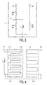
- FIG. 1 shows the circuit diagram of a conventional toaster without asymmetric toasting facility.
- the toaster has two heating elements H1 and H2 disposed at either side of a compartment C. A slice of bread or another food product is inserted between the two heating elements H1 and H2 and toasted at both sides.
- the two heating elements H1 and H2 are connected in series between terminals M1 and M2 to which an alternating voltage is supplied, for example 220 V AC mains voltage.
- Each heating element has a resistance R, so the total resistance seen at the terminals M1 and M2 is 2R.
- This conventional toaster is not suitable for one-side toasting of pieces of baguette, loaves cut lengthwise, crumpets, muffins or the like with a crust at one side which is not to be toasted.
- FIG 2 shows the circuit diagram of a conventional toaster with the two heating elements H1 and H2 connected in parallel.
- the heating element H1 can be switched off with a switch S in series with heating element H1.
- each heating element should have a resistance 4R.
- Such high resistance may cause problems because the wires of the heating elements are rather vulnerable.
- a resistance 2R would be a better choice, but in that case the effective mains voltage has to be reduced accordingly by means of triac control. This solution works well, but is rather expensive.
- One-side toasting is obtained by increasing the resistance of one of the heating elements, for example heating element H1, with respect to the resistance of the other heating element H2.
- the heating element is divided into two sub-elements H1A and H1B.
- Sub-element H1B can be short-circuited with a switch S.
- the two sub-elements H1A and H1B and the heating element H2 are connected in series between the terminals M1 and M2.
- the resistances of sub-element H1A and the resistance of heating element H2 are both equal to R.
- the resistance of sub-element H1B is, by way of example, also equal to R, but any other resistance may be selected as well.
- the toaster When the switch S is closed, the toaster operates in the normal two-sided toasting mode comparable to the configuration shown in Figure 1.
- the switch S When the switch S is open, relatively more heat is radiated by the two sub-elements H1A and H1B.
- the switch S In the case of equal resistances for the sub-elements and the element H2 two thirds of the power is radiated by the two subelements at one side and one third by element H2 at the other side. This is no true one-side toasting, but in practice the effect is the same.
- the two sub-elements H1A and H1B each consist of a winding of heating wire on a support SP1 as shown in Figure 4.
- the turns of the two windings are interspersed (interleaved) because they have to occupy the same area on the support SP1.
- the minimum distance between the adjacent turns of the windings has to fulfil certain requirements. This means that the distance between the turns of the winding of heating sub-element H1A has to be twice the minimum distance in order to give room for the interspersed turns of the winding of sub-element H1B.
- the density of turns of sub-element H1A thus is lower than possible.
- heating element H2 on support SP2 if this element is made of the same heating wire material as sub-element H1A.
- the irradiation of the slice of bread in the normal mode is not as good as compared with conventional toasters without such asymmetric mode.
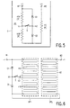
- Figure 5 shows the circuit diagram of a toaster with asymmetric toasting facility according to the invention.
- the two sub-elements H1A and H1B and the heating element H2 are again connected in series between the terminals M1 and M2.
- a series arrangement of two diodes D1 and D2 is connected in parallel with the series arrangement of the two sub-elements H1A and H1B.
- the diodes are interconnected back-to-back, i.e. anode to anode or cathode to cathode, in a node N2.
- diodes are shown.
- Other unidirectional elements such as diode-connected transistors may be used as well.
- the switch S is arranged between the node N2 and the interconnection node N1 of the two sub-elements H1A and H1B.
- the resistance of the sub-elements H1A and HIB and of heating element H2 is preferably the same and equal to R.
- Diode D2 conducts during positive half-waves of the AC mains voltage and current only flows through sub-element H1A.
- the resistance seen between the terminals M1 and M2 is equal to 2R and the heating sub-elements H1A and H1B together radiate as much power as heating element H2.
- the windings of sub-elements H1A and H1B are not interspersed (interleaved) but are located on adjacent parts of the support SP1.
- the number of turns in the winding of sub-element H1A and in the winding of sub-element H1B is half the number of turns in the winding of element H2.
- the specific resistance of the wire used for the sub-elements is two times as high as that of the wire used for element H2. If this different specific resistance is not desired, the element H2 can also be divided into two sub-elements and can be provided with two diodes and a further switch. All four sub-elements then have the same specific resistance.
- the further switch provides the option to select which side of the slice is to be toasted. However, the further switch may be omitted and replaced by a permanent connection.
- the switch between the first node and the second node can be a user-operable electric switch, a relay or a controllable electronic switch, such as a triac driven by a controller CM to change the on-off duty cycle of the triac, as shown in Figure 7.
- a triac the toaster can be adjusted gradually from normal to asymmetric toasting by suitably controlling the on-off duty cycle of the triac.
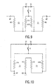
- FIG 8 shows an alternative circuit for the circuits shown in Figures 5 and 7.
- the node N1 and the node N2 are connected directly and the diodes D1 and D2 are replaced by thyristors T1 and T2.
- the trigger gates of the thyristors T1 and T2 receive trigger pulses from a controller CM2.
- CM2 a controller that controls the thyristors at the beginning of the corresponding half-wave of the AC mains voltage
- An asymmetric toasting effect is be obtained by stopping the triggering of the thyristors.
- the toasting effect can be changed gradually from asymmetric to normal.
- Fig. 9 shows a toaster with two compartments C1 and C2 for toasting two slices of bread at the same time, a further second heating element H3 is series connected to the other end of the subdivided first heating element, i.e. between terminal M1 and sub-element H1A, to form two outer heating elements and a switchable centre heating element.
- Fig. 10 shows an alternative arrangement for a toaster with two compartments C1 and C2.
- the switchable sub-elements H1A and H1B are here located at the outer side of the compartments C1 and C2 and the second heating element H2 and the further second heating element H3 are located in the centre.
- the turns of the windings of elements H2 and H3 may be interspersed on a single support or may be accommodated on separate supports.
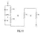
- Fig. 11 shows a second alternative arrangement for a toaster with two compartments C1 and C2.
- the switchable sub-elements H1A and H1B are located at the outer side of compartment C2. This arrangement allows two-sided toasting of one slice of bread in a toaster with two compartments. When only one slice of bread is placed in one of the compartments, the inner face of the slice is toasted faster than the outer face. This is due to the fact that in the free compartment the radiation from the outer element heats up the element in the centre.
- the arrangement with the switchable subelements H1A and H1B can be used to compensate for this effect.
Abstract
Description
Claims (9)
- An electric toaster comprising a first heating element (H1) and a second heating element (H2), the first (H1) and second (H2) heating elements being electrically connected in series for receiving an alternating supply voltage, the first heating element (H1) being divided into two sub-elements (H1A, H1B), the sub-elements (H1A, H1B) being interconnected in a first node (N1) and switching means for activating and deactivating one of said two subelements, characterized in that the switching means for activating and deactivating comprises: a series arrangement of a first unidirectional means (D1) and a second unidirectional means (D2) connected in parallel with said first heating element (H1), the first unidirectional means (D1) and the second unidirectional means (D2) having corresponding electrodes interconnected in a second node (N2), and means (S) for interconnecting the first node (N1) and the second node (N2).
- An electric toaster as claimed in claim 1, characterized in that each of the two sub-elements (H1A, H1B) of the first heating element (H1) has a resistance substantially equal to the resistance of the second heating element (H2).
- An electric toaster as claimed in claim 1 or 2, characterized in that the two sub-elements (H1A, H1B) of the first heating element (H1) are composed of turns of heating wire upon a support (SP1), the individual turns of the two subelements (H1A, H1B) being located on adjacent parts of the support (SP1).
- An electric toaster as claimed in claim 3, characterized in that the second heating element (H2) is composed of turns of heating wire upon a further support (SP2), the number of turns of the second heating element (H2) being substantially equal to the sum of the number of turns of the two sub-elements (H1A, H1B) of the first heating element (H1).
- An electric toaster as claimed in claim 1, 2, 3 or 4, characterized in that the means for interconnecting comprises a user-operable electrical switch (S).
- An electric toaster as claimed in claim 1, 2, 3 or 4, characterized in that the means for interconnecting comprises a bidirectional controllable electronic switch (ES), and in that the electronic toaster further comprises means (CM) for controlling an on-off duty cycle of the electronic switch (ES).
- An electric toaster as claimed in claim 6, characterized in that the first and second unidirectional elements (D1, D2) comprise diodes.
- An electric toaster as claimed in claim 1, 2, 3, or 4, characterized in that the first unidirectional means and the second unidirectional means comprise thyristors (T1, T2), the means for interconnecting being a short-circuit between de first node (N1) and the second node (N2), and in that the electronic toaster further comprises means (CM2) for triggering the thyristors (T1, T2).
- An electric toaster as claimed in claim 8, characterized in that the means (CM2) for triggering are operable to provide trigger pulses to the thyristors (T1, T2), which trigger pulses are present during selected ones of cycles of the alternating supply voltage.
Priority Applications (1)
| Application Number | Priority Date | Filing Date | Title |
|---|---|---|---|
| EP98900119A EP0920274B1 (en) | 1997-01-29 | 1998-01-15 | Electric toaster with asymmetric heating effect |
Applications Claiming Priority (4)
| Application Number | Priority Date | Filing Date | Title |
|---|---|---|---|
| EP97200230 | 1997-01-29 | ||
| EP97200230 | 1997-01-29 | ||
| PCT/IB1998/000058 WO1998032361A1 (en) | 1997-01-29 | 1998-01-15 | Electric toaster with asymmetric heating effect |
| EP98900119A EP0920274B1 (en) | 1997-01-29 | 1998-01-15 | Electric toaster with asymmetric heating effect |
Publications (2)
| Publication Number | Publication Date |
|---|---|
| EP0920274A1 EP0920274A1 (en) | 1999-06-09 |
| EP0920274B1 true EP0920274B1 (en) | 2002-01-23 |
Family
ID=8227958
Family Applications (1)
| Application Number | Title | Priority Date | Filing Date |
|---|---|---|---|
| EP98900119A Expired - Lifetime EP0920274B1 (en) | 1997-01-29 | 1998-01-15 | Electric toaster with asymmetric heating effect |
Country Status (6)
| Country | Link |
|---|---|
| US (1) | US6051818A (en) |
| EP (1) | EP0920274B1 (en) |
| JP (1) | JP3983303B2 (en) |
| AT (1) | ATE212203T1 (en) |
| DE (1) | DE69803540T2 (en) |
| WO (1) | WO1998032361A1 (en) |
Families Citing this family (9)
| Publication number | Priority date | Publication date | Assignee | Title |
|---|---|---|---|---|
| KR100626401B1 (en) * | 2002-09-03 | 2006-09-20 | 엘지전자 주식회사 | Circuit for controlling heater in microwave oven having toaster |
| US20100006561A1 (en) * | 2008-07-11 | 2010-01-14 | Breville Pty Limited | Toaster Oven |
| US20140318382A1 (en) * | 2010-05-11 | 2014-10-30 | Standex International Corporation | Quick heating quartz toaster |
| CA2915995C (en) | 2013-07-09 | 2021-03-23 | Strix Limited | Apparatus for heating food |
| EP2873925B1 (en) * | 2013-11-15 | 2021-07-14 | Electrolux Appliances Aktiebolag | Arrangement to supply a resistive load of a household appliance and method for feeding a resistive load of a household appliance |
| GB201500342D0 (en) | 2015-01-09 | 2015-02-25 | Strix Ltd | Apparatus for heating food |
| EP3426046B1 (en) * | 2016-03-09 | 2023-06-07 | DMP Enterprises Pty Ltd | Conveyor-type oven |
| US10368693B2 (en) | 2017-02-24 | 2019-08-06 | Willard Branch | Food toasting device |
| CN215305176U (en) * | 2021-06-15 | 2021-12-28 | 江门市新会恒隆家居创新用品有限公司 | Toaster |
Family Cites Families (16)
| Publication number | Priority date | Publication date | Assignee | Title |
|---|---|---|---|---|
| US2705276A (en) * | 1954-07-30 | 1955-03-29 | Gen Electric | Heating device control circuit |
| US3247358A (en) * | 1962-09-04 | 1966-04-19 | Norman L Chalfin | Dual heat level soldering iron |
| US3681569A (en) * | 1967-12-22 | 1972-08-01 | Hercules Galion Prod Inc | Heat control system |
| US3692975A (en) * | 1971-03-26 | 1972-09-19 | Joseph Markus | Food preparing system for passenger carrying conveyances |
| US4085309A (en) * | 1975-06-04 | 1978-04-18 | Sperry Rand Corporation | Control circuit arrangement for a portable electrically heated hair treatment appliance |
| US4296312A (en) * | 1979-06-01 | 1981-10-20 | General Electric Company | Electronic temperature sensing system for toaster appliances |
| US4487115A (en) * | 1983-07-13 | 1984-12-11 | Su Cheng Hsiung | Toaster |
| US4538049A (en) * | 1984-04-03 | 1985-08-27 | Black & Decker, Inc. | Toaster oven |
| FR2648034B1 (en) * | 1989-06-09 | 1994-07-08 | Seb Sa | MULTIPURPOSE TOASTER |
| US5218185A (en) * | 1989-08-15 | 1993-06-08 | Trustees Of The Thomas A. D. Gross 1988 Revocable Trust | Elimination of potentially harmful electrical and magnetic fields from electric blankets and other electrical appliances |
| ES2020837A6 (en) * | 1990-01-31 | 1991-10-01 | Agrupada Invest Off | Improvements in household toasters. |
| US5094154A (en) * | 1990-08-27 | 1992-03-10 | Black & Decker Inc. | Electric toaster with time delay mechanism |
| DE4446796C2 (en) * | 1994-12-24 | 1998-01-29 | Rowenta Werke Gmbh | Circuit arrangement for an electric toaster, fed by a mains voltage |
| US5698123A (en) * | 1996-01-16 | 1997-12-16 | Black & Decker Inc. | Toaster compensation for repeated use |
| US5844207A (en) * | 1996-05-03 | 1998-12-01 | Sunbeam Products, Inc. | Control for an electric heating device for providing consistent heating results |
| US5705791A (en) * | 1996-12-20 | 1998-01-06 | Whirlpool Corporation | Automatic toaster and a control therefor |
-
1998
- 1998-01-15 AT AT98900119T patent/ATE212203T1/en not_active IP Right Cessation
- 1998-01-15 WO PCT/IB1998/000058 patent/WO1998032361A1/en active IP Right Grant
- 1998-01-15 EP EP98900119A patent/EP0920274B1/en not_active Expired - Lifetime
- 1998-01-15 DE DE69803540T patent/DE69803540T2/en not_active Expired - Fee Related
- 1998-01-15 JP JP52919398A patent/JP3983303B2/en not_active Expired - Lifetime
- 1998-01-27 US US09/014,171 patent/US6051818A/en not_active Expired - Fee Related
Also Published As
| Publication number | Publication date |
|---|---|
| WO1998032361A1 (en) | 1998-07-30 |
| JP3983303B2 (en) | 2007-09-26 |
| JP2000508758A (en) | 2000-07-11 |
| US6051818A (en) | 2000-04-18 |
| EP0920274A1 (en) | 1999-06-09 |
| ATE212203T1 (en) | 2002-02-15 |
| DE69803540D1 (en) | 2002-03-14 |
| DE69803540T2 (en) | 2002-09-05 |
Similar Documents
| Publication | Publication Date | Title |
|---|---|---|
| US4198553A (en) | Combination oven fully utilizing the capability of a limited power source | |
| EP0920274B1 (en) | Electric toaster with asymmetric heating effect | |
| CA1253598A (en) | Power control arrangement | |
| US3320396A (en) | Electronic oven | |
| US5438914A (en) | Electric circuit for controlling the heat output of heating resistances in household appliances | |
| US6495809B2 (en) | Electrical heater with thermistor | |
| RU2668069C2 (en) | Improved tortilla toaster | |
| DE2921266A1 (en) | MICROWAVE COOKING OR BAKING APPLIANCE | |
| EP0804049A2 (en) | Radiant electric heater arrangement | |
| JPH081829B2 (en) | Device for induction heating of flat metal materials | |
| US5170039A (en) | Multifunction toaster | |
| CA1310055C (en) | Controllable electric heater | |
| GB2329769A (en) | Electric heater control | |
| US2084881A (en) | Electric toaster | |
| AU650523B2 (en) | Electric toasters | |
| GB2531599A (en) | Energy saving electric toaster | |
| WO2004019726A1 (en) | Hair dryer with improved heating power control and circuits therefor | |
| JPH02114488A (en) | Induction heating cooker | |
| CN217959744U (en) | Circuit system and cooking utensil | |
| JP7325273B2 (en) | heating cooker | |
| US20220151434A1 (en) | Cooking appliance employing radiative flux | |
| JPS6343739Y2 (en) | ||
| JP2002050455A (en) | Surface-formed heat generation body and thermal equipment using it | |
| GB2246033A (en) | Control circuit for an electric heating appliance | |
| JPH03163787A (en) | Microwave oven |
Legal Events
| Date | Code | Title | Description |
|---|---|---|---|
| PUAI | Public reference made under article 153(3) epc to a published international application that has entered the european phase |
Free format text: ORIGINAL CODE: 0009012 |
|
| 17P | Request for examination filed |
Effective date: 19990201 |
|
| AK | Designated contracting states |
Kind code of ref document: A1 Designated state(s): AT DE FR GB NL |
|
| GRAG | Despatch of communication of intention to grant |
Free format text: ORIGINAL CODE: EPIDOS AGRA |
|
| GRAG | Despatch of communication of intention to grant |
Free format text: ORIGINAL CODE: EPIDOS AGRA |
|
| GRAG | Despatch of communication of intention to grant |
Free format text: ORIGINAL CODE: EPIDOS AGRA |
|
| GRAH | Despatch of communication of intention to grant a patent |
Free format text: ORIGINAL CODE: EPIDOS IGRA |
|
| 17Q | First examination report despatched |
Effective date: 20010611 |
|
| GRAH | Despatch of communication of intention to grant a patent |
Free format text: ORIGINAL CODE: EPIDOS IGRA |
|
| GRAA | (expected) grant |
Free format text: ORIGINAL CODE: 0009210 |
|
| REG | Reference to a national code |
Ref country code: GB Ref legal event code: IF02 |
|
| AK | Designated contracting states |
Kind code of ref document: B1 Designated state(s): AT DE FR GB NL |
|
| PG25 | Lapsed in a contracting state [announced via postgrant information from national office to epo] |
Ref country code: NL Free format text: LAPSE BECAUSE OF FAILURE TO SUBMIT A TRANSLATION OF THE DESCRIPTION OR TO PAY THE FEE WITHIN THE PRESCRIBED TIME-LIMIT Effective date: 20020123 Ref country code: AT Free format text: LAPSE BECAUSE OF FAILURE TO SUBMIT A TRANSLATION OF THE DESCRIPTION OR TO PAY THE FEE WITHIN THE PRESCRIBED TIME-LIMIT Effective date: 20020123 |
|
| REF | Corresponds to: |
Ref document number: 212203 Country of ref document: AT Date of ref document: 20020215 Kind code of ref document: T |
|
| REF | Corresponds to: |
Ref document number: 69803540 Country of ref document: DE Date of ref document: 20020314 |
|
| ET | Fr: translation filed | ||
| NLV1 | Nl: lapsed or annulled due to failure to fulfill the requirements of art. 29p and 29m of the patents act | ||
| PLBE | No opposition filed within time limit |
Free format text: ORIGINAL CODE: 0009261 |
|
| STAA | Information on the status of an ep patent application or granted ep patent |
Free format text: STATUS: NO OPPOSITION FILED WITHIN TIME LIMIT |
|
| 26N | No opposition filed | ||
| PGFP | Annual fee paid to national office [announced via postgrant information from national office to epo] |
Ref country code: GB Payment date: 20090202 Year of fee payment: 12 |
|
| PGFP | Annual fee paid to national office [announced via postgrant information from national office to epo] |
Ref country code: DE Payment date: 20090313 Year of fee payment: 12 |
|
| PGFP | Annual fee paid to national office [announced via postgrant information from national office to epo] |
Ref country code: FR Payment date: 20090127 Year of fee payment: 12 |
|
| GBPC | Gb: european patent ceased through non-payment of renewal fee |
Effective date: 20100115 |
|
| REG | Reference to a national code |
Ref country code: FR Ref legal event code: ST Effective date: 20100930 |
|
| PG25 | Lapsed in a contracting state [announced via postgrant information from national office to epo] |
Ref country code: FR Free format text: LAPSE BECAUSE OF NON-PAYMENT OF DUE FEES Effective date: 20100201 |
|
| PG25 | Lapsed in a contracting state [announced via postgrant information from national office to epo] |
Ref country code: DE Free format text: LAPSE BECAUSE OF NON-PAYMENT OF DUE FEES Effective date: 20100803 |
|
| PG25 | Lapsed in a contracting state [announced via postgrant information from national office to epo] |
Ref country code: GB Free format text: LAPSE BECAUSE OF NON-PAYMENT OF DUE FEES Effective date: 20100115 |