JP3978523B2 - Power supply device, electronic device and power supply system - Google Patents
Power supply device, electronic device and power supply system Download PDFInfo
- Publication number
- JP3978523B2 JP3978523B2 JP2002016652A JP2002016652A JP3978523B2 JP 3978523 B2 JP3978523 B2 JP 3978523B2 JP 2002016652 A JP2002016652 A JP 2002016652A JP 2002016652 A JP2002016652 A JP 2002016652A JP 3978523 B2 JP3978523 B2 JP 3978523B2
- Authority
- JP
- Japan
- Prior art keywords
- power supply
- electronic device
- power
- output
- voltage
- Prior art date
- Legal status (The legal status is an assumption and is not a legal conclusion. Google has not performed a legal analysis and makes no representation as to the accuracy of the status listed.)
- Expired - Fee Related
Links
Images


Landscapes
- Power Sources (AREA)
Description
【0001】
【発明の属する技術分野】
本発明は電源装置並びに電子機器に係り、特に電源電圧の異なる複数の電子機器に対して適切な電圧を設定して供給する電源装置並びに電子機器に関する。
【0002】
【従来の技術】
電源電圧の異なる複数の電子機器を、1個の直流電源装置で使用出来るようにして携帯性を高め、且つ、電圧の設定誤りによる電子器の損傷や動作不良を防止することが可能な直流電源装置が、特開平11-353041号の公報に示されている。
【0003】
該直流電源装置は、電圧値を決定するための電圧制御端子を有し、接続中継部は直流電源部を負荷機器に接続し、且つ上記直流電源部の電圧制御端子へ電圧情報を与えるための電圧情報端子を有する。また、上記直流電源部に対して上記接続中継部は接続器により着脱可能であり、複数の電子機器のそれぞれの異なる電源電圧に対応した複数の接続中継部の中の1つを上記直流電源部に接続するものである。
【0004】
また、インピーダンス素子を持つ電源供給アダプタから得られるID信号に対応した電源電流を電源ユニットから出力することが可能な電源供給アダプタ、電源ユニット、電子機器及び電源供給システムが、特開2001−142577号の公報に示されている。
【0005】
該電源供給アダプタ等では、接続されている電子機器のIDを検出して、そのID信号に応じて電源回路のスイッチング動作を制御して電圧電流を出力している。
【0006】
【発明が解決しようとする課題】
しかしながら、従来の特開平11-353041号の公報に示されている直流電源装置では、定電圧電源のフィードバック信号発生のための分圧抵抗を、機器本体側に埋め込むことにより、機器ごとに最適な電源電圧を自動的に設定するようにしたものであり、機器に最適な電源電圧を提供することは可能であるが、機器の電流容量が電源側の容量を超える場合であってもその検出ができないという不具合を生じていた。したがって、機器側の電流容量が電源の供給可能な容量を超える場合には、電源の供給を明示的に停止するのが最良であるが、電源の供給を停止することが出来ないという不具合を生じていた。
【0007】
また、特開2001−142577号の公報に示されている電源供給アダプタ等では、予めインピーダンスに機器種別を割り当てているために、新規の機種に未対応の旧式の電源装置では対応できないという不具合を生ずる。更に、外部の電子機器へ供給する際の電流容量不足等に関する欠点は、上述の引例と同一である。
【0008】
また、上述の何れの装置を用いても、電源電圧が所定の電圧値に静定するまでの間は、過電圧又は低電圧等が機器側に印加されてしまうという不具合を生ずる。
【0009】
本発明は、このような事情に鑑みてなされたもので、任意の電子機器に対して、電源装置側の供給能力の範囲内で最適な電圧の電源を生成して供給することが可能な電源装置を提供することを目的としている。
【0010】
また本発明は、任意の電子機器の消費電流が当該電源装置の供給可能な許容電流を超える場合には、電力供給前にこれを検出して電源の供給を行わないようにすることが可能な電源装置を提供することを目的としている。
【0011】
また本発明は、電源装置の電源供給能力に応じて通常動作を実施することが可能な電子機器を提供することを目的としている。
【0012】
また本発明は、電源装置の電源供給能力が当該電子機器の消費電流を満たしている場合にのみ電源装置に対して電力の供給開始を指示することが可能な電子機器を提供することを目的としている。
【0013】
【課題を解決するための手段】
本発明は前記目的を達成するために、電子機器に電力を供給する電源装置において、電子機器から該電子機器にて使用する電源電圧に関する情報を受信する受信手段と、前記電子機器から受信した電源電圧に関する情報に基づいて当該電源装置が出力する供給電圧を制御する出力電圧制御手段とを備えたことを特徴としている。
【0014】
本発明によれば電源装置において、電子機器から受信した該電子機器が使用する電源電圧に関する情報に基づいて、該電子機器に出力する供給電圧を制御する出力電圧制御手段を備えたので、任意の電子機器に対して電源装置側の供給能力の範囲内で最適な電圧の電源を生成して供給することが可能となる。
【0015】
また本発明は前記目的を達成するために、電子機器に電力を供給する電源装置において、当該電源装置が電子機器に対して供給可能な許容電流値を記録する記録手段と、電子機器から該電子機器にて消費する消費電流値に関する情報を受信する受信手段と、前記記録手段に記録されている許容電流値を読み出して前記受信した電子機器の消費電流値が前記許容電流値以内であるか否かを判断する判断手段と、前記判断の結果電子機器の消費電流値が前記許容電流値以内でない場合には電子機器に対して消費電流値を設定することができない旨を示す設定不可メッセージを送信する送信手段とを備えたことを特徴としている。
【0016】
本発明によれば、電力を供給する対象の電子機器から受信手段が受信した消費電流値が、記録手段に記録されている当該電源装置にて供給可能な許容電流値以内でない場合には、前記電子機器に対して消費電流値を設定することができない旨を示す設定不可メッセージを送信する送信手段を備えたので、任意の電子機器の消費電流が当該電源装置の供給可能な許容電流を超える場合には、電力供給前にこれを検出して電源の供給を行わないようにすることが可能となる。
【0017】
また本発明は前記目的を達成するために、電源装置から電力の供給を受ける電子機器において、当該電子機器にて使用する電源電圧に関する情報又は当該電子機器にて消費する消費電流値に関する情報を電源装置に送信する送信手段と、前記電源装置が前記送信した電源電圧及び消費電流値にて電力を供給することが可能である旨の設定完了メッセージを前記電源装置から受信する受信手段と、前記電源装置から設定完了メッセージを受信すると当該電子機器の通常動作を開始する旨の判断を実施する情報処理手段、又は、前記電源装置に対して電力の供給の開始を指示する出力ONメッセージを送信する指示を前記送信手段を介して出力する情報処理手段とを備えたことを特徴としている。
【0018】
本発明によれば電子機器において、当該電子機器の電源電圧又は消費電流値を電源装置に対して送信手段が送信し、前記電源装置から前記送信した電源電圧又は消費電流値にて電力を供給することが可能である旨の設定完了メッセージを前記電源装置から受信手段が受信すると、当該電子機器の通常動作を実施する旨の判断を実施する情報処理手段、又は、前記電源装置に対して電力の供給の開始を指示する出力ONメッセージを送信する指示を前記送信手段を介して出力する情報処理手段を備えたので、電源装置の電源供給能力に応じて当該電子機器の通常動作を実施することが可能となる。
【0019】
また本発明によれば電子機器において、電源装置の電源供給能力が当該電子機器の消費電流を満たしている場合にのみ電源装置に対して電力の供給開始を指示することが可能となる。したがって本発明に係る電子機器によれば、電子機器の消費電流が電源装置が供給可能な許容電流を超える場合には、電力供給前にこれを検出して電源の供給を行わないようにすることが可能となる。
【0020】
【発明の実施の形態】
以下添付図面に従って、本発明に係る電源装置並びに電子機器の好ましい実施の形態について詳説する。
【0021】
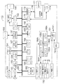
図1に、電源装置50から電力の供給を受ける電子機器の信号処理系ブロック図を示す。
【0022】
同図に示すように、電子機器の一形態である電子カメラ10の撮像処理部には、受光面に結像した被写体像を光電変換して画像信号として出力する撮像手段150と、アナログ信号用の信号処理手段153と、アナログの画像信号をデジタルの画像データに変換するA/D変換器154とが設けられている。
【0023】
また、画像データ等の情報を携帯電話等の他の通信機器と送受信するための通信手段として、画像データ等の情報を無線通信用の搬送波に乗せて送信又は受信する送受信手段157と、画像ファイル等の情報を送受信するアンテナ156とが設けられている。また、画像データ等の情報を携帯電話等の他の通信機器と送受信するための他の通信手段として、画像データ等の情報をシリアル通信を介して送信又は受信するシリアルインターフェース164(送信手段、受信手段)が設けられている。
【0024】
また、電子カメラ10には、画像データの圧縮処理等を実施する圧縮伸張手段167と、各種の文字を画像とともに表示手段168にオンスクリーンディスプレイするOSD169と、表示用の画像データを一時的に記憶しておくフレームメモリ171と、デジタルの画像データを表示用のコンポジット信号等に変換して表示手段168に出力する表示制御手段172とが設けられている。
【0025】
また、電子カメラ10には、電源スイッチやレリーズボタン等から構成される入力手段174と、入力手段174を介して入力された入力情報を変換して情報処理手段に伝達するI/O175と、記録媒体177を着脱可能に装着する記録媒体装着部178と、記録媒体177に対して画像データ等の情報を記録したり読み出したりする記録媒体インターフェース179とが設けられている。
【0026】
また、電子カメラ10には、電子カメラ10全体の制御を行うとともに画像処理や通信処理を実施する情報処理手段180と、情報の書き換えが可能であるとともに記憶した調整用の各種定数等を記憶する不揮発性メモリ182と、電子カメラ10の動作プログラム及び定数等が記憶されているROMやプログラム実行時の作業領域となるRAMとから構成されているメモリ181とが設けられている。
【0027】
なお情報処理手段180は、画像データに対してホワイトバランス処理を実施したり、ガンマ変換、YC変換処理、画素数の変換処理、電子ズーム処理、トリミング処理等を実施することが可能となっている。
【0028】
また、電子カメラ10には、時を刻むカレンダ時計190と、情報処理手段180の設定によって所定の時間を係数してその結果を情報処理手段180に伝達するタイマ190Aと、電子カメラ10を駆動するための電力を切り換えて供給する切り替え手段191と、充電可能な電池191Aと、外部の電源装置50から電力の供給を受ける電源コネクタ192と、撮像時に光を発光して被写体の光量不足を補う発光手段193と、該発光手段193の発光タイミング等の調節を行う発光制御手段194とが設けられている。
【0029】
なお、同図に示すように電子カメラ10の情報処理手段180とその周辺の各回路はバス199で接続されており、互いに情報の伝達を高速で行うことが可能であるとともに、情報処理手段180が実行する処理プログラムに基づいて周辺の各回路を制御することが可能となっている。
【0030】
また、電子カメラ10には、電源装置50と当該電子カメラ10にて利用する電源電圧や消費電流等に関する情報の送受信を実施するシリアルインターフェース164A(送信手段、受信手段)と、電源装置50との通信処理や、当該電子カメラ10にて利用する電源を切り換える指示を切り替え手段191に対して出力する制御を行うサブの情報処理手段180Aと、当該電子カメラ10にて利用する電源電圧や消費電流に関する情報や電源装置50との送受信に関する処理プログラム等を記録しているROM183A(記録手段)と、情報処理手段180のワークエリアとなるRAM184Aと、情報処理手段180Aの指示に基づいて切り替え手段191に電源の切替を指示する信号を出力するI/O188Aとが設けられている。
【0031】
なお、同図に示すように電子カメラ10のサブの情報処理手段180Aとその周辺の各回路はバス199Aで接続されており、互いに情報の伝達を高速で行うことが可能であるとともに、情報処理手段180Aが実行する処理プログラムに基づいて周辺の各回路を制御することが可能となっている。
【0032】
また、上記のサブの情報処理手段180Aとその周辺回路は、コネクタ192に設けられているサブ電源入力端子を介して入力した電力によって動作するように構成されている。したがって、電池191Aの消耗度合いやコネクタ192を介して入力されるメイン電源の電圧に関わりなく動作することが可能となっている。
【0033】
また、コネクタ192のメイン電源端子を介して供給されるメイン電源は、サブの情報処理手段180Aの判断により電池191Aの状況等によって切り換えて、電子カメラ10の各回路に供給することが可能となっている。なお、同図には示していないが、電池191Aを電源装置50から供給されるメイン電源によって充電することが可能な充電回路を設けてもよい。
【0034】
なお、上記の説明では、電子カメラ10の全体の制御を実施する情報処理手段180とは別に、消費電力の少ないサブの情報処理手段180Aを設けてメイン電源供給前に電源装置50と情報の送受信を実施する例で示したが、本発明はこの構成に限定されるものではなく、情報処理手段180Aを別途設けずに、メイン電源が供給されていない状態では消費電力を押さえるために情報処理手段180の動作クロックを落とすとともに、メモリ181、シリアルインターフェース164等の通信に必要な周辺回路のみに通電して、シリアルインターフェース164を介して電源装置50と電源電圧や消費電流に関する情報の送受信を実施するように構成しても本発明の目的を達成することが可能である。
【0035】
なお、送受信手段(シリアルインターフェース164又は164A)は、当該電子機器にて使用する電源電圧に関する情報又は当該電子機器にて消費する消費電流値に関する情報を電源装置50に送信することが可能となっている。
【0036】
また、送受信手段(シリアルインターフェース164又は164A)は、電源装置50が送信した電源電圧及び消費電流値にて電力を供給することが可能である旨の「設定完了メッセージ」を、電源装置50から受信することが可能となっている。
【0037】
また情報処理手段180又は180Aは、電源装置50から「設定完了メッセージ」を受信すると、電子カメラ10(電子機器)の通常動作を開始して、撮像や画像の閲覧等の処理を実施することが可能となっている。また、情報処理手段180又は180Aは、電源装置50から「設定完了メッセージ」を受信すると、電源装置50に対して電力の供給の開始を指示する旨の「出力ONメッセージ」を送信する指示を、シリアルインターフェース164又は164A(送信手段)を介して出力することが可能となっている
上記の説明では、本発明に係る電子機器を電子カメラ10とした例で説明したが、本発明はこれに限定されるものではなく、パソコン、携帯電話、電子手帳、MDレコーダ、CDレコーダその他の電子機器であってもよい。
【0038】
図2に、本発明に係る電源装置の電力制御系ブロック図を示す。
【0039】
同図に示すように電源装置50の電力生成部には、交流商用電源等から電力を入力するAC入力手段550と、電子カメラ10等の任意の電子機器に適合した電圧の電力を供給するメイン電源出力端子を備えるとともに通信用の端子等を備えた入出力コネクタ551と、商用電源の交流を直流に変換するとともに脈流を平滑化する機能を備えた整流平滑手段562と、整流平滑手段562から出力される直流電圧に対して、デューティー比を変更するなどのパルス幅変調を行って所定の電圧に変換する出力電圧制御手段570(スイッチングレギュレータ)とが設けられている。
【0040】
図2に示す例では、パルス幅を変調して出力電圧を制御する手段を用いている実施例で説明しているが、本発明はこれに限定されるものではなく、シリーズレギュレータ、切替式のドロッパ等の出力電圧制御手段を用いても本発明の目的を達成することが可能である。
【0041】
入出力コネクタ551には、接続先の電子機器に動作電力を供給するメイン電源出力及びその接地端子と、接続先の電子機器のサブの情報処理手段180A等に電力を供給するサブ電源出力端子と、シリアル通信入出力I/F用の通信端子と、電子機器を接続したことを検出する接続検出端子と、サブ電源及び通信用の共通接地端子とが設けられている。
【0042】
入出力コネクタ551に設けられている接続検出端子はプルアップ抵抗を介してI/O588に入力されている。また接続検出端子は、接続先の電子機器では接地するように構成されているので、電子機器と入出力コネクタとが接続されていない場合には接続検出端子の状態は「1」となり、電子機器と入出力コネクタとが接続されている場合には接続検出端子の状態は「0」となる。この接続検出端子の状態を情報処理手段580が読み取って、メイン電源出力やサブ電源出力等の供給電力の制御を実施することが可能となっている。
【0043】
また、電源装置50の電力生成部には、出力電流を検出して過電流による電子機器や電源装置50の損傷を防止する電流検出手段571と、過電圧を供給してしまうことによる電子機器や電源装置50の損傷を防止するとともに電子機器に適切な出力電圧を供給するために出力電圧を検出する電圧検出手段572と、電子機器に対して供給する電力を遮断する制御を行う出力制御手段573(リレー、アナログスイッチ等から構成されていてもよい)と、電子機器に供給するサブ電源の過電流に対する保護を行う過電流保護手段574とが設けられている。
【0044】
また、電源装置50の電力生成部には、当該電力制御部や電子機器で利用する電圧を出力する定電圧回路563とが設けられている。なお、定電圧回路563が出力する電圧は、出力電圧制御手段570が出力し得る電圧範囲のうちの最低電圧値としてもよい。また電圧検出手段572は、抵抗器により出力電圧を分圧した電圧を検出する構成であってもよい。
【0045】
また、電源装置50の電力制御部には、電源装置50全体の制御を実施することが可能な情報処理手段(CPU)580と、情報処理手段580が実行する処理プログラムや各種の設定定数等の情報が記録されているROM583と、情報処理手段580が演算処理を実施する際のワークエリアとなるRAM584とが設けられている。
【0046】
また、電源装置50の電力制御部には、情報処理手段580の指示に基づいて、電力を供給する電子機器と供給電圧や供給電力に関する情報の送受信を行うシリアルインターフェース又はパラレルインターフェース等の送受信手段585と、電力を供給する電子機器との接続の確認や、電源装置50内の出力制御手段573等の周辺回路とステータスの入出力を行うI/O588と、最初の電源投入時や電圧降下時に情報処理手段580に対してパワーオンリセット信号等を出力するリセット手段595とが設けられている。
【0047】
また、電源装置50の電力制御部には、情報処理手段580の指示に基づいて出力電圧制御手段570が出力する電圧を制御する情報を出力するD/A変換器596と、電流検出手段571が検出したアナログの電流情報や電圧検出手段572が検出したアナログの電圧情報をデジタルデータに変換して情報処理手段580に伝達するA/D変換器598とが設けられている。なお、当該電力制御部は、ワンチップマイコンやASIC等で構成されていてもよい。
【0048】
同図に示すように電源装置50の情報処理手段580とその周辺の各回路はバス599で接続されており、互いに情報の伝達を高速で行うことが可能であるとともに、情報処理手段580が実行する処理プログラムに基づいて周辺の各回路を制御することが可能となっている。
【0049】
また電源装置50は、出力電圧制御手段570が出力した電圧を電流検出手段571、電圧検出手段572、出力制御手段573及び入出力コネクタ551を介して電子カメラ10等の電子機器に供給することが可能となっている。
【0050】
情報処理手段580は、電圧検出手段572から取得した出力電圧情報と設定電圧値又は参照電圧値とを比較して、出力電圧制御手段570に対してスイッチング素子のデューティー比を制御する指令を出力することによって、目標の出力電圧を出力するように制御することが可能となっている。
【0051】
なお電流検出手段571は、出力電圧に関係なくハードウェアにて所定の許容電流値(プログラマブルな許容電流値であってもよい)以内に出力電流を制限する機能を有している。この過電流保護機能により、過電流が電子機器に対して出力された際に、情報処理手段580がその過電流となった電流値を読み取って出力を遮断する保護機能が動作を開始するまでのタイムラグの間においても、システムを過電流から保護することが可能となっている。
【0052】
なお情報処理手段580は、電流検出手段571が検出した出力電流情報と許容電流値とを比較して、許容電流値を超えた場合にはI/O588を介して出力制御手段573に対して出力電圧を遮断する指令を出力して、電子機器に対する電力の供給を停止することが可能となっている。また、出力制限する許容電流値は、電子機器から通信によって取得した電子機器固有の許容電流値(設定要求メッセージ)を設定するようにしてもよい。
【0053】
送受信手段585(受信手段)は、電子カメラ10(電子機器)から該電子カメラ10にて使用する電源電圧、又は消費電流値に関する情報を受信することが可能となっている。
【0054】
出力電圧制御手段570は、電子カメラ10から受信した電源電圧に関する情報に基づいて当該電源装置50が出力する供給電圧を制御することが可能となっている。
【0055】
また情報処理手段580(判断手段)は、ROM583等の記録手段に記録されている許容電流値を読み出して、送受信手段585を介して受信した電子カメラ10の消費電流値が前記許容電流値以内であるか否かを判断することが可能となっている。
【0056】
前記判断の結果、電子カメラ10の消費電流値が前記許容電流値以内でない場合には、情報処理手段580は送受信手段585を介して電子カメラ10に対して、消費電流値を設定することができない旨を示す「設定不可メッセージ」を送信することが可能となっている。
【0057】
図3に、電源装置50が電子機器に対して出力する供給電圧と許容電流との関係例を記載した図表を示す。
【0058】
同図に示すように、電源装置50は約15Wの電力を出力することが可能となっている。電源装置50が電子カメラ10等の電子機器に出力する電源電圧は、情報処理手段580の指示によって自在に変更することが可能となっている。なお、この図3に示す供給電圧と許容電流との関係は、ROM583に記録されており、情報処理手段580が読み出すことが可能となっている。
【0059】
図4に、入出力コネクタ551の外観斜視図を示す。
【0060】
同図に示すように、メイン電源出力端子とメイン電源用の接地端子は大電流を送電しても大きな電圧降下が発生しないように太い端子(ピン)が設けられている。また、サブ電源出力端子(ピン)及びサブ電源及び通信用接地端子(ピン)は他の端子よりも長く構成されており、入出力コネクタ551を電子カメラ10のコネクタ192に接続する際において、先に電子カメラ10の情報処理手段180A等の回路にサブ電源を供給することが可能となっている。したがって、シリアル通信入出力端子が電子カメラ10側のシリアル入出力端子と接続された時点では、既にシリアルインターフェース164A等のイニシャライズが終了しているため、送受信手段585等がシリアルインターフェース164A起動時に発するゴミの信号を拾って情報処理手段580が誤動作することを防止できる。
【0061】
図5に、本発明に係る電源装置50及び電子機器間で実施する通信処理及び電圧設定処理に関するフローチャートを示す。
【0062】
利用者が電源装置50のAC入力手段550を商用電源に接続すると、S100「AC投入」(以降S100のように省略して記載する)にて電源装置50に電力が供給される。すると電源装置50の整流平滑手段562からは直流が出力され、その電圧を用いて定電圧回路563がサブ電源を出力する。当該サブ電源の電圧が、情報処理手段580を動作させるのに適した電圧にまで達すると、リセット手段595は情報処理手段580に対してリセット信号を出力する。
【0063】
情報処理手段580が当該リセット信号を取得すると、情報処理手段580が実施する処理はS102「リセット」に進み、処理プログラムを最初から起動若しくは所定の番地から開始する処理を行う。S102にて情報処理手段580の処理が所定の番地から起動すると、情報処理手段580はD/A変換器596や送受信手段585等の各種周辺機器の初期化処理を行う。この初期化処理にて、出力制御手段573に対してはメイン電源出力を遮断する指示を出力しておく。該初期化処理が終了すると、情報処理手段580が実施する処理は次のS104「接続検出?」の処理に進む。
【0064】
S104にて情報処理手段580は、I/O588に接続されている接続検出端子の状態を観察して、電力を供給すべき電子機器が接続されるのを待つ処理を行っている。もし接続検出端子の状態が「1」である場合には、電子機器は未接続であると判断して、再びS104に戻る。
【0065】
一方、利用者によって電源装置50の入出力コネクタ551が電子カメラ10のコネクタ192と接続されると、図4に示した入出力コネクタ551の形状では先ずサブ電源が先に投入される。したがって、電子カメラ10側の処理はS200「コネクタ接続」からS202「サブ電源投入」に進む。サブ電源が所定の電圧値に達すると、情報処理手段180Aが実施する処理はS204「リセット」に進み、処理プログラムを最初から起動若しくは所定の番地から開始する処理を行う。
【0066】
また、利用者によって電源装置50の入出力コネクタ551が電子カメラ10のコネクタ192と完全に接続されると、入出力コネクタ551に設けられている接続検出端子が、電子カメラ10側で接地されるために、「1」から「0」の状態に遷移する。
【0067】
するとその接続検出端子の情報は、I/O588を介して情報処理手段580が読み取る。S104の判断にて接続検出端子の状態が「0」となった場合には、電子カメラ10と接続されたと判断して、情報処理手段580が実施する処理は次のS106「設定要求メッセージ待ち 電圧V、電流I」の判断に進む。S106では、シリアル通信入出力インターフェース端子を介して「電圧V」及び「電流I」のメッセージ情報を取得するのを待つ処理を行う。
【0068】
一方電子カメラ10側では、S204にて情報処理手段180Aの処理が所定の番地から起動して、接続されている各種周辺機器の初期化処理を終了すると、情報処理手段180Aが実施する処理は次のS206「設定要求メッセージ送信電圧V、電流I」に進む。S206にて情報処理手段180Aは、ROM183Aに記録されている当該電子機器で利用する電源の電圧値V又は消費電流値Iを含む電源の設定要求メッセージを読み出して、シリアルインターフェース164Aとコネクタ192とを介して電源装置50側に送信する処理を行う。
【0069】
一方、電子カメラ10側から発信された設定要求メッセージを、入出力コネクタ551及び送受信手段585を介して情報処理手段580が受信すると、情報処理手段50が実施する処理は、S108「要求電圧Vに対する電流容量読み取り Imax (V)」の処理に進む。S108にて情報処理手段580は、所定の供給電圧(V)に許容されている許容電流値(Imax )をROM583から読み出す処理を行う。ROM583から許容電流値(Imax )を読み出すと、情報処理手段580が実施する処理はS110「電源供給可否判断 Vmin ≦V≦Vmax and I≦Imax (V)」の判断に進む。
【0070】
S110で情報処理手段580は、先ず所定の供給電圧(V)が、当該電源装置50で出力可能な供給電圧の範囲(Vmin ≦V≦Vmax の範囲)に存在しているか否かの判断を行っている。もし所定の供給電圧(V)が、当該電源装置で出力可能な供給電圧の範囲に含まれていないと判断した場合には、処理はS112「設定不可メッセージ送信」に進む。
【0071】
また、もし所定の供給電圧(V)が、当該電源装置50で出力可能な供給電圧の範囲に含まれていると判断した場合には、次に電子カメラ10の消費電流(I)が当該電源装置50の所定の供給電圧(V)における出力可能な許容電流(Imax )以内であるか否かの判断を行う。もし電子カメラ10の消費電流(I)が、当該電源装置50の所定の供給電圧(V)における出力可能な許容電流(Imax )以内でないと判断した場合には、処理はS112「設定不可メッセージ送信」の処理に進む。
【0072】
またS110の判断にて、電子機器の消費電流(I)が当該電源装置50の所定の供給電圧(V)における出力可能な許容電流(Imax )以内であると判断した場合には、処理は次のS118「出力電圧をVに設定」処理に進む。
【0073】
S112にて情報処理手段580は、当該電源装置50では電子カメラ10が設定を要求している電源容量を満足しないとの判断(S110における判断)の結果から、出力電圧又は出力電流を設定することができない旨を示す「設定不可メッセージ」を、送受信手段585及び入出力コネクタ551を介して電子カメラ10に送信する処理を行う。なお、図5では「設定不可メッセージ」のようなエラーメッセージの伝達状況を破線で表している。
【0074】
また、次のS114「エラー表示」では、図示しないLED等のパイロットランプ等を点灯又は点滅させて、エラーの発生を利用者に対して通知する。次のS116「接続検出?」の判断では、入出力コネクタ551が電子カメラ10から抜去されるのを待つ処理を行っている。もし入出力コネクタ551と電子カメラ10との接続が切り離された場合には、処理はS102に戻り再びリセット処理を実施して初期状態に戻る。
【0075】
また、S118にて情報処理手段580は、電圧検出手段572が出力する電圧情報をA/D変換器598を介して取得して観察しながら、電子カメラ10が要求する所定の供給電圧に設定する情報を、D/A変換器596を介して出力電圧制御手段570に指示する。
【0076】
次のS120「出力電圧はVに安定化したか?」の判断では、電圧検出手段572が出力する電圧情報が、所定の供給電圧の範囲内に達するのを待つ処理を行う。もし、S120にて電圧検出手段572が出力する電圧情報が所定の供給電圧の範囲内に達したと判断した場合には、情報処理手段580が実施する処理は、S122「設定完了メッセージ送信」に進む。
【0077】
S122にて情報処理手段580は、電圧検出手段572が出力する電圧情報が所定の供給電圧に達したことを示す「設定完了メッセージ」を、送受信手段585を介して電子カメラ10に送信する処理を行う。
【0078】
一方、電子カメラ10の情報処理手段180Aは、S208「メッセージ応答待ち」の判断にて「送信不可メッセージ」又は「設定完了メッセージ」を受信するのを待つ処理を行っている。S208にて電源装置50からメッセージを受信すると、処理は次のS210「メッセージは?」の判断に進む。
【0079】
S210の判断にて、S208にて取得したメッセージが「設定不可」を示すメッセージであると判断した場合には、処理はS212「エラー表示」の処理に分岐して、図示しないLED等のパイロットランプに対して点灯又は点滅する指示を出力して利用者にその旨を通知し、S220「コネクタ離脱」に進む。
【0080】
またS210の判断にて、S208にて取得したメッセージが「設定完了」を示すメッセージであると判断した場合には、処理はS214「出力ONメッセージ送信」の処理に進む。S214にて情報処理手段180Aは、シリアルインターフェース164Aを介して「出力ONメッセージ」を電源装置50に対して送信する指示を出力する。
【0081】
一方、電源装置50の情報処理手段580が、S124にて電子カメラ10から「出力ONメッセージ」を送受信手段585を介して取得すると、処理はS126「出力ON」の処理に進む。S126にて情報処理手段580は、I/O588を介して出力制御手段573に対してメイン電源出力を電子カメラ10に対して供給通電する旨の指示を出力する。すると、電子カメラ10に対してメイン電源が供給される。そして情報処理手段580が実施する処理は、S132「接続検出?」の判断に進む。
【0082】
一方、電源装置50からメイン電源の供給を受けている電子カメラ10側では、情報処理手段180AがI/O188Aを介して当該電子カメラ10にて利用する電力の供給元をメイン電源入力側に設定する指示を切替手段191に出力する。すると切替手段191は、当該電子カメラ10で利用する電源を、コネクタ192を介して入力している電源に切り換える。すると電子カメラ10では、S216「機器の通常動作」にて、撮像処理や撮像した画像の閲覧等の処理を実施することが可能となる。利用者が電子カメラ10の操作を終了して、電子カメラ10の電源を遮断する処理等を入力手段174を介して指示した場合には、情報処理手段180Aが実施する処理はS218「出力OFFメッセージ送信」に進む。
【0083】
S218にて情報処理手段180Aは、シリアルインターフェース164Aを介して電源装置50に対して電源の「出力OFFメッセージ」を送信する指示を出力する。
【0084】
一方、電源装置50側の情報処理手段580は、S126、S128、S132を経由するループ処理を行っている。もし、電源装置50が電子カメラ10から「出力OFFメッセージ」を受信すると、情報処理手段580が実施する処理はS128「出力OFFメッセージあり?」の判断からS130「出力OFF」の処理に分岐する。
【0085】
S130にて情報処理手段580は、I/O588を介して出力制御手段573に対してメイン電源出力を電子カメラ10に対して遮断する旨の指示を出力する。すると、電子カメラ10に対して供給されていたメイン電源は遮断される。そして情報処理手段580が実施する処理は、次のS132の判断に進む。
【0086】
S132にて情報処理手段580は、I/O588に接続されている接続検出端子の状態を観察して、入出力コネクタ551が電子機器と接続されているか否かの判断を行っている。S132の判断にて、電子機器が接続されていると判断した場合には、処理はS124に戻る。
【0087】
また、S132にて入出力コネクタ551が電子機器から抜去されて未接続であると判断した場合には、処理はS102に戻り、電源装置側の処理はリセットされて初期状態に戻る。このようにして、電源装置50と電子カメラ10との間における電源電圧(V)及び電源電流(I)に関するネゴシエーションは、入出力コネクタ551接続後に1回だけ行われる。
【0088】
以上のようにして電源装置50は、接続された電子機器から使用する電源電圧(V)と消費電流(I)に関する情報を取得して、出力電圧を所定の電圧値に設定し、電子機器に対して供給するようにしているので、使用する電源電圧が異なる複数の電子機器に対しても適宜電圧値を設定して供給することが可能となっている。
【0089】
したがって、旅行や出張にでかける際に電子カメラ10や携帯電話、パソコン、電子手帳、髭剃り器等の、電源電圧の異なる複数の電子機器を持ってゆく場合であっても、電源装置は1つだけ持ってゆけばこと足りるので、軽快かつ快適な旅行や出張を楽しむことが可能となる。
【0090】
【発明の効果】
以上説明したように本発明に係る電源装置によれば、電子機器から受信した該電子機器が使用する電源電圧に関する情報に基づいて、該電子機器に出力する供給電圧を制御する出力電圧制御手段を備えたので、任意の電子機器に対して電源装置側の供給能力の範囲内で最適な電圧の電源を生成して供給することが可能となる。
【0091】
また本発明に係る電源装置によれば、電力を供給する対象の電子機器から受信手段が受信した消費電流値が、記録手段に記録されている当該電源装置にて供給可能な許容電流値以内でない場合には、前記電子機器に対して消費電流値を設定することができない旨を示す設定不可メッセージを送信する送信手段を備えたので、任意の電子機器の消費電流が当該電源装置の供給可能な許容電流を超える場合には、電力供給前にこれを検出して電源の供給を行わないようにすることが可能となる。
【0092】
また本発明に係る電子機器によれば、当該電子機器の電源電圧又は消費電流値を電源装置に対して送信手段が送信し、前記電源装置から前記送信した電源電圧又は消費電流値にて電力を供給することが可能である旨の設定完了メッセージを前記電源装置から受信手段が受信すると、当該電子機器の通常動作を実施する旨の判断を実施する情報処理手段、又は、前記電源装置に対して電力の供給の開始を指示する出力ONメッセージを送信する旨の指示を前記送信手段を介して出力する情報処理手段を備えたので、電源装置の電源供給能力に応じて当該電子機器の通常動作を実施することが可能となる。また本発明によれば電子機器において、電源装置の電源供給能力が当該電子機器の消費電流を満たしている場合にのみ電源装置に対して電力の供給開始を指示することが可能となる。
【0093】
したがって、電子機器の消費電流が電源装置が供給可能な許容電流を超える場合には、電力供給前にこれを検出して電源の供給を行わないようにすることが可能となる。
【0094】
また、本発明に係る電源装置及び電子機器によれば、予め電子機器と電源装置との間で電源電圧や消費電流に関する情報の送受信を行って、電子機器に供給する電源電圧や電流容量に関するネゴシエーションを実施して、その後電源装置側で供給する電圧の設定を行い、当該供給電圧が安定化したことを確認した後に、電源の供給を開始することが可能となる。したがって、任意の電子機器に対して電源装置側の供給能力の範囲内で最適な電圧の電源を提供することが可能となる。
【0095】
また、本発明に係る電源装置によれば、供給する電源電圧が静定して安定になった後に、電子機器に対して電力の供給を開始することが可能となる。
【図面の簡単な説明】
【図1】電源装置から電力の供給を受ける電子機器の信号処理系ブロック図
【図2】本発明に係る電源装置の電力制御系ブロック図
【図3】電源装置が電子機器に対して出力する供給電圧と許容電流との関係例を記載した図表
【図4】入出力コネクタの外観斜視図
【図5】本発明に係る電源装置及び電子機器間で実施する通信処理及び電圧設定処理に関するフローチャート
【符号の説明】
10…電子カメラ、50…電源装置、150…撮像手段、153…信号処理手段、154…A/D変換器、156…アンテナ、157…送受信手段、164、164A…シリアルインターフェース、167…圧縮伸張手段、168…表示手段、169…OSD、171…フレームメモリ、172…表示制御手段、174…入力手段、175…I/O、177…記録媒体、178…記録媒体装着部、179…記録媒体インターフェース、180、180A…情報処理手段、181…メモリ、182…不揮発性メモリ、183A…ROM、184A…RAM、188A…I/O、190…カレンダ時計、190A…タイマ、191…切替手段、191A…電池、192…コネクタ、193…発光手段、194…発光制御手段、199、199A…バス、550…AC入力手段、551…入出力コネクタ、562…整流平滑手段、563…定電圧回路、570…出力電圧制御手段、571…電流検出手段、572…電圧検出手段、573…出力制御手段、574…過電流保護手段、580…情報処理手段、583…ROM、584…RAM、585…送受信手段、588…I/O、595…リセット手段、596…D/A変換器、598…A/D変換器、599…バス[0001]
BACKGROUND OF THE INVENTION
The present invention relates to a power supply device and an electronic device, and more particularly to a power supply device and an electronic device that set and supply an appropriate voltage to a plurality of electronic devices having different power supply voltages.
[0002]
[Prior art]
A DC power supply that allows multiple electronic devices with different power supply voltages to be used with a single DC power supply device to improve portability and prevent damage to electronic devices and malfunction due to incorrect voltage settings An apparatus is shown in Japanese Patent Laid-Open No. 11-353041.
[0003]
The DC power supply device has a voltage control terminal for determining a voltage value, and the connection relay unit connects the DC power supply unit to a load device and provides voltage information to the voltage control terminal of the DC power supply unit. It has a voltage information terminal. Further, the connection relay unit can be attached to and detached from the DC power supply unit by a connector, and one of the plurality of connection relay units corresponding to different power supply voltages of the plurality of electronic devices is connected to the DC power supply unit. To connect to.
[0004]
Japanese Patent Application Laid-Open No. 2001-142577 discloses a power supply adapter, a power supply unit, an electronic device, and a power supply system that can output a power supply current corresponding to an ID signal obtained from a power supply adapter having an impedance element. It is shown in the gazette.
[0005]
The power supply adapter or the like detects the ID of the connected electronic device and controls the switching operation of the power supply circuit according to the ID signal to output a voltage / current.
[0006]
[Problems to be solved by the invention]
However, in the conventional DC power supply device disclosed in Japanese Patent Laid-Open No. 11-353041, a voltage dividing resistor for generating a feedback signal of a constant voltage power supply is embedded in the device main body side, so that it is optimal for each device. Although the power supply voltage is set automatically, it is possible to provide the optimal power supply voltage for the device, but the detection is possible even when the current capacity of the device exceeds the capacity on the power supply side. There was a problem that it was not possible. Therefore, when the current capacity on the equipment side exceeds the capacity that can be supplied with power, it is best to explicitly stop the supply of power, but there is a problem that the supply of power cannot be stopped. It was.
[0007]
In addition, in the power supply adapter disclosed in Japanese Patent Application Laid-Open No. 2001-142577, since the device type is assigned to the impedance in advance, there is a problem that an old power supply device that does not support a new model cannot be used. Arise. Furthermore, the drawbacks relating to insufficient current capacity when supplying to external electronic devices are the same as in the above-mentioned reference.
[0008]
Moreover, even if any of the above-described devices is used, there is a problem that an overvoltage or a low voltage is applied to the device until the power supply voltage is settled to a predetermined voltage value.
[0009]
The present invention has been made in view of such circumstances, and is a power source capable of generating and supplying a power source having an optimum voltage within a range of a power supply device-side supply capability to an arbitrary electronic device. The object is to provide a device.
[0010]
Further, according to the present invention, when the consumption current of an arbitrary electronic device exceeds the allowable current that can be supplied by the power supply device, it is possible to detect this before supplying power and not to supply power. The object is to provide a power supply.
[0011]
Another object of the present invention is to provide an electronic device capable of performing a normal operation according to the power supply capability of the power supply device.
[0012]
Another object of the present invention is to provide an electronic device capable of instructing the power supply device to start supplying power only when the power supply capability of the power supply device satisfies the current consumption of the electronic device. Yes.
[0013]
[Means for Solving the Problems]
In order to achieve the above object, the present invention provides a power supply apparatus for supplying power to an electronic device, a receiving means for receiving information on a power supply voltage used in the electronic device from the electronic device, and a power supply received from the electronic device. Output voltage control means for controlling the supply voltage output from the power supply unit based on information on the voltage.
[0014]
According to the present invention, the power supply device includes the output voltage control means for controlling the supply voltage output to the electronic device based on the information on the power supply voltage used by the electronic device received from the electronic device. It is possible to generate and supply a power supply having an optimum voltage within the range of the supply capability on the power supply device side to the electronic device.
[0015]
In order to achieve the above object, the present invention provides a power supply device for supplying power to an electronic device, a recording means for recording an allowable current value that can be supplied to the electronic device by the power supply device, and an electronic device from the electronic device. Receiving means for receiving information related to the current consumption value consumed by the device, and whether or not the current consumption value of the received electronic device is within the allowable current value by reading the allowable current value recorded in the recording means A determination means for determining whether or not the current consumption value of the electronic device is not within the allowable current value as a result of the determination, and a setting disable message indicating that the current consumption value cannot be set is transmitted to the electronic device And a transmission means.
[0016]
According to the present invention, when the consumption current value received by the receiving unit from the electronic device to which power is supplied is not within the allowable current value that can be supplied by the power supply device recorded in the recording unit, Since the transmission means for transmitting the setting impossible message indicating that the current consumption value cannot be set for the electronic device is provided, the current consumption of any electronic device exceeds the allowable current that can be supplied by the power supply device In this case, it is possible to prevent this from being performed by detecting this before supplying power.
[0017]
In order to achieve the above object, according to the present invention, in an electronic device that is supplied with power from a power supply device, information on a power supply voltage used in the electronic device or information on a current consumption value consumed in the electronic device is Transmitting means for transmitting to the apparatus; receiving means for receiving from the power supply apparatus a setting completion message indicating that the power supply apparatus can supply power with the transmitted power supply voltage and current consumption value; and the power supply Information processing means for performing a determination to start normal operation of the electronic device upon receiving a setting completion message from the device, or an instruction to transmit an output ON message instructing the power supply device to start power supply And an information processing means for outputting the information via the transmission means.
[0018]
According to the present invention, in the electronic device, the transmission means transmits the power supply voltage or current consumption value of the electronic device to the power supply device, and supplies power from the power supply device using the transmitted power supply voltage or current consumption value. When the receiving means receives from the power supply device a setting completion message indicating that the electronic device can be used, the information processing means for performing the determination that the normal operation of the electronic device is to be performed, or the power supply to the power supply device Since the information processing means for outputting an instruction to transmit an output ON message for instructing the start of supply via the transmission means is provided, the normal operation of the electronic device can be performed according to the power supply capability of the power supply device. It becomes possible.
[0019]
Further, according to the present invention, in the electronic device, it is possible to instruct the power supply device to start supplying power only when the power supply capability of the power supply device satisfies the current consumption of the electronic device. Therefore, according to the electronic device according to the present invention, when the consumption current of the electronic device exceeds the allowable current that can be supplied by the power supply device, this is detected before the power supply and the power supply is not performed. Is possible.
[0020]
DETAILED DESCRIPTION OF THE INVENTION
Hereinafter, preferred embodiments of a power supply device and an electronic apparatus according to the present invention will be described in detail with reference to the accompanying drawings.
[0021]
FIG. 1 shows a block diagram of a signal processing system of an electronic device that receives power from the
[0022]
As shown in the figure, an imaging processing unit of an
[0023]
Also, as a communication means for transmitting / receiving information such as image data to / from other communication devices such as a mobile phone, a transmission / reception means 157 for transmitting or receiving information such as image data on a wireless communication carrier, and an image file Etc., and an
[0024]
The
[0025]
In addition, the
[0026]
Further, the
[0027]
Note that the
[0028]
The
[0029]
As shown in the figure, the information processing means 180 of the
[0030]
In addition, the
[0031]
As shown in the figure, the sub information processing means 180A of the
[0032]
Also, the sub information processing means 180A and its peripheral circuits are configured to operate with electric power input via a sub power input terminal provided on the
[0033]
Further, the main power supplied via the main power terminal of the
[0034]
In the above description, in addition to the
[0035]
Note that the transmission / reception means (
[0036]
Further, the transmission / reception means (
[0037]
When the
In the above description, the example in which the electronic apparatus according to the present invention is the
[0038]
FIG. 2 shows a block diagram of a power control system of the power supply device according to the present invention.
[0039]
As shown in the figure, the power generation unit of the
[0040]
In the example shown in FIG. 2, the embodiment using the means for controlling the output voltage by modulating the pulse width is described. However, the present invention is not limited to this, but a series regulator, a switching type The object of the present invention can also be achieved by using an output voltage control means such as a dropper.
[0041]
The input /
[0042]
A connection detection terminal provided in the input /
[0043]
In addition, the power generation unit of the
[0044]
In addition, the power generation unit of the
[0045]
The power control unit of the
[0046]
In addition, the power control unit of the
[0047]
The power control unit of the
[0048]
As shown in the figure, the information processing means 580 of the
[0049]
Further, the
[0050]
The
[0051]
The
[0052]
The information processing means 580 compares the output current information detected by the current detection means 571 with the allowable current value, and outputs the output to the output control means 573 via the I /
[0053]
The transmission / reception unit 585 (reception unit) can receive information on the power supply voltage or current consumption value used in the
[0054]
The output voltage control means 570 can control the supply voltage output from the
[0055]
Further, the information processing means 580 (determination means) reads the allowable current value recorded in the recording means such as the
[0056]
As a result of the determination, if the current consumption value of the
[0057]
FIG. 3 is a chart showing an example of the relationship between the supply voltage output from the
[0058]
As shown in the figure, the
[0059]
FIG. 4 shows an external perspective view of the input /
[0060]
As shown in the figure, the main power supply output terminal and the main power supply ground terminal are provided with thick terminals (pins) so that a large voltage drop does not occur even when a large current is transmitted. Also, the sub power output terminal (pin) and the sub power and communication ground terminal (pin) are longer than the other terminals, and when connecting the input /
[0061]
FIG. 5 is a flowchart regarding communication processing and voltage setting processing performed between the
[0062]
When the user connects AC input means 550 of
[0063]
When the
[0064]
In S104, the information processing means 580 performs processing for observing the state of the connection detection terminal connected to the I /
[0065]
On the other hand, when the input /
[0066]
Further, when the input /
[0067]
Then, the information of the connection detection terminal is read by the information processing means 580 via the I /
[0068]
On the other hand, on the
[0069]
On the other hand, when the
[0070]
In S110, the
[0071]
If it is determined that the predetermined supply voltage (V) is included in the range of the supply voltage that can be output by the
[0072]
If it is determined in S110 that the consumption current (I) of the electronic device is within the allowable current (Imax) that can be output at the predetermined supply voltage (V) of the
[0073]
In S112, the information processing means 580 sets the output voltage or the output current based on the result of the determination that the
[0074]
In the next S114 “error display”, a pilot lamp such as an LED (not shown) is turned on or blinked to notify the user of the occurrence of an error. In the next determination of S116 “connection detection?”, A process of waiting for the input /
[0075]
In S118, the
[0076]
In the next determination of S120, “Is the output voltage stabilized at V?”, A process of waiting for the voltage information output by the voltage detection means 572 to reach within a predetermined supply voltage range is performed. If it is determined in S120 that the voltage information output by the
[0077]
In step S122, the
[0078]
On the other hand, the
[0079]
If it is determined in S210 that the message acquired in S208 is a message indicating “cannot be set”, the process branches to the process of S212 “Error display”, and a pilot lamp such as an LED (not shown). An instruction to turn on or blink is output to the user, and the user is notified of this, and the process proceeds to S220 “connector disconnection”.
[0080]
If it is determined in S210 that the message acquired in S208 is a message indicating “setting complete”, the process proceeds to S214 “output ON message transmission”. In S214, the
[0081]
On the other hand, when the
[0082]
On the other hand, on the side of the
[0083]
In S218, the information processing means 180A outputs an instruction to transmit the “output OFF message” of the power supply to the
[0084]
On the other hand, the
[0085]
In S <b> 130, the
[0086]
In S132, the
[0087]
If it is determined in S132 that the input /
[0088]
As described above, the
[0089]
Therefore, even when taking a plurality of electronic devices having different power supply voltages, such as the
[0090]
【The invention's effect】
As described above, according to the power supply device of the present invention, the output voltage control means for controlling the supply voltage output to the electronic device based on the information on the power supply voltage used by the electronic device received from the electronic device. Since it is provided, it becomes possible to generate and supply power of an optimal voltage to an arbitrary electronic device within the range of the supply capability on the power supply device side.
[0091]
According to the power supply device of the present invention, the current consumption value received by the receiving means from the electronic device to which power is supplied is not within the allowable current value that can be supplied by the power supply device recorded in the recording means. In this case, the power supply device can supply current consumption of an arbitrary electronic device because it includes a transmission unit that transmits a setting impossible message indicating that the current consumption value cannot be set to the electronic device. If the allowable current is exceeded, this can be detected before power supply to prevent power supply.
[0092]
According to the electronic device of the present invention, the transmission means transmits the power supply voltage or current consumption value of the electronic device to the power supply device, and the power is supplied from the power supply device using the transmitted power supply voltage or current consumption value. When the receiving unit receives a setting completion message indicating that the electronic device can be supplied from the power supply unit, the information processing unit that performs a determination to perform normal operation of the electronic device or the power supply unit Since the information processing means for outputting an instruction to transmit an output ON message for instructing the start of power supply is provided via the transmission means, the normal operation of the electronic device is performed according to the power supply capability of the power supply device. It becomes possible to carry out. Further, according to the present invention, in the electronic device, it is possible to instruct the power supply device to start supplying power only when the power supply capability of the power supply device satisfies the current consumption of the electronic device.
[0093]
Therefore, when the consumption current of the electronic device exceeds the allowable current that can be supplied by the power supply device, it is possible to detect this before supplying power and not supply power.
[0094]
In addition, according to the power supply device and the electronic device according to the present invention, information relating to the power supply voltage and current consumption is transmitted and received between the electronic device and the power supply device in advance, and negotiation regarding the power supply voltage and current capacity supplied to the electronic device is performed. After that, after setting the voltage to be supplied on the power supply device side and confirming that the supply voltage has stabilized, the supply of power can be started. Therefore, it becomes possible to provide a power supply having an optimum voltage within a range of the supply capability on the power supply device side for any electronic device.
[0095]
Further, according to the power supply device of the present invention, it is possible to start supplying power to the electronic device after the power supply voltage to be supplied is stabilized and stabilized.
[Brief description of the drawings]
FIG. 1 is a block diagram of a signal processing system of an electronic device that is supplied with power from a power supply device.
FIG. 2 is a block diagram of a power control system of a power supply device according to the present invention.
FIG. 3 is a chart describing an example of the relationship between the supply voltage output from the power supply device to the electronic device and the allowable current
FIG. 4 is an external perspective view of an input / output connector.
FIG. 5 is a flowchart regarding communication processing and voltage setting processing performed between the power supply apparatus and the electronic apparatus according to the invention.
[Explanation of symbols]
DESCRIPTION OF
Claims (9)
電子機器から該電子機器にて使用する電源電圧に関する情報および該電子機器にて消費する消費電流値に関する情報を受信する受信手段と、
各電子機器にて使用する電源電圧と前記電源電圧において供給可能な許容電流値とを対応づけた電圧電流関係情報を記録する記録手段と、
前記記録手段に記録された電圧電流関係情報のうち前記受信手段の受信した電源電圧に対応する許容電流値と、前記受信手段の受信した消費電流値とを比較することで、前記電子機器が要求する電力を供給可能か否かを判断する判断手段と、
前記判断手段が、前記電子機器が要求する電力を供給可能であると判断したことに応じ、該電子機器に出力する供給電圧を制御する出力電圧制御手段と、
前記電子機器にメインの動作電力を供給するメイン電源出力端子と、
少なくとも電子機器のサブの情報処理手段および情報送受信手段に電源を供給するサブ電源出力端子と、
を備え、
前記サブ電源出力端子は、前記メイン電源出力端子よりも長く構成されており、前記電子機器のサブの情報処理手段および情報送受信手段に電源を先に供給可能であることを特徴とする電源装置。In a power supply device that supplies power to an electronic device,
Receiving means for receiving information on the power supply voltage used in the electronic device and information on the current consumption value consumed in the electronic device from the electronic device;
Recording means for recording voltage-current relation information in which a power supply voltage used in each electronic device is associated with an allowable current value that can be supplied at the power supply voltage;
The electronic device requests by comparing the allowable current value corresponding to the power supply voltage received by the receiving unit with the current consumption value received by the receiving unit among the voltage-current related information recorded in the recording unit. Determining means for determining whether or not the power to be supplied can be supplied;
An output voltage control means for controlling a supply voltage output to the electronic device in response to determining that the electric power required by the electronic device can be supplied by the determining means;
A main power output terminal for supplying main operating power to the electronic device;
A sub power output terminal for supplying power to at least the sub information processing means and the information transmitting / receiving means of the electronic device;
With
The sub power supply output terminal is configured to be longer than the main power supply output terminal, and is capable of supplying power first to the sub information processing means and information transmission / reception means of the electronic device.
前記電源装置のメイン電源出力端子と接続するメイン入力端子と、
前記メイン電源出力端子よりも長く構成された前記電源装置のサブ電源出力端子と接続するサブ入力端子と、
前記サブ入力端子を介して供給された電力によって動作可能であり、当該電子機器にて使用する電源電圧に関する情報又は当該電子機器にて消費する消費電流値に関する情報を前記電源装置に送信するとともに、前記電源装置から前記送信した電源電圧及び消費電流値にて電力を供給することが可能である旨の設定完了メッセージを前記電源装置から受信する情報送受信手段と、
前記サブ入力端子を介して供給された電力によって動作可能であり、前記電源装置から前記設定完了メッセージを受信すると、当該電子機器の通常動作を開始する旨の判断を実施するか、又は前記電源装置に対して電力の供給の開始を指示する出力ONメッセージを送信する指示を前記情報送受信を介して出力する情報処理手段と、
を備えたことを特徴とする電子機器。In an electronic device that receives power supply from a power supply device,
A main input terminal connected to a main power output terminal of the power supply;
A sub input terminal connected to a sub power output terminal of the power supply device configured to be longer than the main power output terminal;
It is operable with the power supplied through the sub input terminal, and transmits information on the power supply voltage used in the electronic device or information on the current consumption value consumed in the electronic device to the power supply device Information transmitting / receiving means for receiving from the power supply device a setting completion message indicating that power can be supplied from the power supply device with the transmitted power supply voltage and current consumption value;
It is operable with the power supplied via the sub input terminal, and upon receiving the setting completion message from the power supply device, the electronic device is judged to start normal operation or the power supply device Information processing means for outputting an instruction to transmit an output ON message for instructing start of power supply to the device via the information transmission / reception;
An electronic device characterized by comprising:
前記情報処理手段は、前記設定完了メッセージを受信したことに応じ、電力の供給元を前記メイン入力端子に切り替える指示を前記切替手段に出力することを特徴とする請求項5又は6に記載の電子機器。In accordance with an instruction from the information processing means, the apparatus further comprises switching means for switching the power supply source to either the main input terminal or the sub input terminal,
Said information processing means, in response to receiving the setting completion message, electrons according to instruction for switching the power source of the main input terminal to Claim 5 or 6, characterized in that output to the switching means machine.
前記電源装置から電力を供給される電子機器と、
を備えたことを特徴とする電力供給システム。The power supply device according to any one of claims 1 to 4 ,
An electronic device to which power is supplied from the power supply device;
A power supply system comprising:
前記電子機器に電力を供給する電源装置と、
を備えたことを特徴とする電力供給システム。An electronic device according to any one of claims 5 to 7 ,
A power supply for supplying power to the electronic device;
A power supply system comprising:
Priority Applications (1)
| Application Number | Priority Date | Filing Date | Title |
|---|---|---|---|
| JP2002016652A JP3978523B2 (en) | 2002-01-25 | 2002-01-25 | Power supply device, electronic device and power supply system |
Applications Claiming Priority (1)
| Application Number | Priority Date | Filing Date | Title |
|---|---|---|---|
| JP2002016652A JP3978523B2 (en) | 2002-01-25 | 2002-01-25 | Power supply device, electronic device and power supply system |
Publications (3)
| Publication Number | Publication Date |
|---|---|
| JP2003216284A JP2003216284A (en) | 2003-07-31 |
| JP2003216284A5 JP2003216284A5 (en) | 2005-03-10 |
| JP3978523B2 true JP3978523B2 (en) | 2007-09-19 |
Family
ID=27652645
Family Applications (1)
| Application Number | Title | Priority Date | Filing Date |
|---|---|---|---|
| JP2002016652A Expired - Fee Related JP3978523B2 (en) | 2002-01-25 | 2002-01-25 | Power supply device, electronic device and power supply system |
Country Status (1)
| Country | Link |
|---|---|
| JP (1) | JP3978523B2 (en) |
Families Citing this family (9)
| Publication number | Priority date | Publication date | Assignee | Title |
|---|---|---|---|---|
| JP4221437B2 (en) | 2003-11-07 | 2009-02-12 | エムパシックス エルエルシー | Automatic power detection system and method |
| US8296587B2 (en) | 2006-08-30 | 2012-10-23 | Green Plug, Inc. | Powering an electrical device through a legacy adapter capable of digital communication |
| KR101305508B1 (en) * | 2006-09-18 | 2013-09-05 | 삼성전자주식회사 | Computer and Control Method Therof |
| JP5292776B2 (en) | 2007-07-19 | 2013-09-18 | ソニー株式会社 | Transmission device, power supply switching method for transmission device, reception device, and power supply method for reception device |
| JP2009278771A (en) * | 2008-05-14 | 2009-11-26 | Mitsubishi Electric Corp | Voltage-variable dc power supply device and electric apparatus |
| WO2010067400A1 (en) * | 2008-12-11 | 2010-06-17 | 富士通株式会社 | Power use method, slave device, and computer program |
| JP2011034306A (en) * | 2009-07-31 | 2011-02-17 | Toshiba Corp | Information processor and power supply control method |
| KR101214218B1 (en) * | 2010-11-18 | 2012-12-20 | 주식회사 현대케피코 | Apparatus for driving regulator-independent CPU's standby RAM and method thereof |
| WO2015141644A1 (en) * | 2014-03-19 | 2015-09-24 | ソニー株式会社 | Electronic apparatus, power source reception method in electronic apparatus, power source supply method in electronic apparatus, and cable |
-
2002
- 2002-01-25 JP JP2002016652A patent/JP3978523B2/en not_active Expired - Fee Related
Also Published As
| Publication number | Publication date |
|---|---|
| JP2003216284A (en) | 2003-07-31 |
Similar Documents
| Publication | Publication Date | Title |
|---|---|---|
| US6151652A (en) | I/O card, electronic equipment using I/O card, and procedure of starting up such electronic equipment | |
| US20070055805A1 (en) | Control system, electronic device and image forming apparatus | |
| JP3978523B2 (en) | Power supply device, electronic device and power supply system | |
| JPH09103037A (en) | Power supply unit, unit to be supplied with power and power supply system | |
| US9395781B2 (en) | Electronic device to perform enumeration without power request to an external device when electronic device is on | |
| US11455012B2 (en) | USB docking station with output power adjustment and method thereof | |
| KR101134743B1 (en) | Apparatus and method for downloading or transmitting data under the condition of battery power deficit in portable electronic device | |
| CN110970967A (en) | Electronic apparatus, control method, and storage medium | |
| US20180109106A1 (en) | Electric apparatus and power control method | |
| JP4112341B2 (en) | Printing system and digital camera compatible with this system | |
| JP6257336B2 (en) | IMAGING DEVICE AND IMAGING DEVICE CONTROL METHOD | |
| US20130061079A1 (en) | Image processing apparatus, method for controlling the same and storage medium | |
| JP2010206948A (en) | Information apparatus and charging method of information apparatus | |
| JP2004260911A (en) | Ac adapter | |
| JP7122590B2 (en) | Imaging device | |
| JP4099015B2 (en) | Cradle | |
| JP2006211858A (en) | Charger | |
| JP6754996B1 (en) | Imaging device | |
| JP2002010508A (en) | Apparatus and method for charging | |
| JP2023043758A (en) | Usb port controller and electronic device | |
| JP6961369B2 (en) | Power supply device, control method and program of power supply device | |
| JP2004236426A (en) | Battery charging/discharging control device | |
| JP2005125634A (en) | Printer having charger of mobile phone and printing system | |
| JP7390464B2 (en) | Electronic devices, accessories, operating methods and programs for electronic devices, operating methods and programs for accessories | |
| JP4617829B2 (en) | Portable communication device and battery switching method |
Legal Events
| Date | Code | Title | Description |
|---|---|---|---|
| A521 | Written amendment |
Free format text: JAPANESE INTERMEDIATE CODE: A523 Effective date: 20040402 |
|
| A621 | Written request for application examination |
Free format text: JAPANESE INTERMEDIATE CODE: A621 Effective date: 20040402 |
|
| A977 | Report on retrieval |
Free format text: JAPANESE INTERMEDIATE CODE: A971007 Effective date: 20060531 |
|
| A131 | Notification of reasons for refusal |
Free format text: JAPANESE INTERMEDIATE CODE: A131 Effective date: 20060602 |
|
| A521 | Written amendment |
Free format text: JAPANESE INTERMEDIATE CODE: A523 Effective date: 20060714 |
|
| A711 | Notification of change in applicant |
Free format text: JAPANESE INTERMEDIATE CODE: A712 Effective date: 20061207 |
|
| A131 | Notification of reasons for refusal |
Free format text: JAPANESE INTERMEDIATE CODE: A131 Effective date: 20070308 |
|
| A521 | Written amendment |
Free format text: JAPANESE INTERMEDIATE CODE: A523 Effective date: 20070507 |
|
| TRDD | Decision of grant or rejection written | ||
| A01 | Written decision to grant a patent or to grant a registration (utility model) |
Free format text: JAPANESE INTERMEDIATE CODE: A01 Effective date: 20070525 |
|
| A61 | First payment of annual fees (during grant procedure) |
Free format text: JAPANESE INTERMEDIATE CODE: A61 Effective date: 20070607 |
|
| R150 | Certificate of patent or registration of utility model |
Free format text: JAPANESE INTERMEDIATE CODE: R150 |
|
| FPAY | Renewal fee payment (event date is renewal date of database) |
Free format text: PAYMENT UNTIL: 20100706 Year of fee payment: 3 |
|
| FPAY | Renewal fee payment (event date is renewal date of database) |
Free format text: PAYMENT UNTIL: 20110706 Year of fee payment: 4 |
|
| LAPS | Cancellation because of no payment of annual fees |