JP2004236426A - Battery charging/discharging control device - Google Patents
Battery charging/discharging control device Download PDFInfo
- Publication number
- JP2004236426A JP2004236426A JP2003021535A JP2003021535A JP2004236426A JP 2004236426 A JP2004236426 A JP 2004236426A JP 2003021535 A JP2003021535 A JP 2003021535A JP 2003021535 A JP2003021535 A JP 2003021535A JP 2004236426 A JP2004236426 A JP 2004236426A
- Authority
- JP
- Japan
- Prior art keywords
- battery
- adapter
- unit
- switch
- charge
- Prior art date
- Legal status (The legal status is an assumption and is not a legal conclusion. Google has not performed a legal analysis and makes no representation as to the accuracy of the status listed.)
- Pending
Links
Images

Abstract
Description
【0001】
【発明の属する技術分野】
本発明はバッテリー充放電制御装置に関し、更に詳しくはバッテリーとACアダプタを使用する電子機器において、バッテリーの残量又は電圧によって、バッテリーの充放電を制御し、バッテリーの劣化を少なくするようにしたバッテリーの充放電制御装置に関する。
【0002】
【従来の技術】
充電式バッテリー又はACアダプタを使用して稼働する電子機器では、ACアダプタ使用時でもバッテリーの充電をバッテリーの残量に関係なく行なっている。
【0003】
この種の従来技術としては、使用状況や動作状況に応じて、過充電を起こさないように適切に内蔵2次電池を充電できるようにした技術がある(例えば特許文献1参照)。
【0004】
【特許文献1】
特開平8−186942号公報(第2頁、第3頁、図1)
【0005】
【発明が解決しようとする課題】
前述の従来技術は、内蔵2次電池(バッテリー)が過充電を起こさないように、一定の条件の下にバッテリーの充電を制御するようにしたものである。しかしながら、バッテリーは充放電を繰り返すとその特性が劣化するものであるが、従来技術では、充放電の繰り返しによるバッテリーの特性の劣化防止については考慮されていなかった。
【0006】
本発明はこのような課題に鑑みてなされたものであって、バッテリーの劣化防止を図ることができるバッテリー充放電制御装置を提供することを目的としている。
【0007】
【課題を解決するための手段】
(1)請求項1記載の発明は、以下の通りである。図1は本発明の原理ブロック図である。図において、1はACアダプタ、2はACアダプタ1が入力され、電源電圧を発生させる電源部、3は該電源部2からパワーの供給を受ける電子機器である。該電子機器3としては、電源で動作するあらゆる種類のものが含まれる。
【0008】
電源部2において、10はACアダプタ1が接続されたことを識別するACアダプタ識別部、11はバッテリー、SW1はACアダプタ1の出力とバッテリー11間を接続するオン/オフスイッチである。12はバッテリー11の状態を監視するバッテリー状態監視部である。該バッテリー状態監視部12は、例えばバッテリー11の残量や、バッテリー11の出力電圧を監視し、監視結果に応じて前記スイッチSW1のオン/オフを制御する。
【0009】
13はACアダプタ1の出力とバッテリー出力とを受け、何れか一方を選択して電子機器3に出力する電源切換部である。該電源切換部13において、SW2はACアダプタ1の出力又はバッテリー11の出力の何れか一方を選択して電子機器3に与えるスイッチである。該電源切換部13には、ACアダプタ識別部10からスイッチSW2を制御するための制御信号が与えられている。また、ACアダプタ識別部10は、スイッチSW1のオン/オフも制御する。バッテリー状態監視部12は前記スイッチSW1のオン/オフの制御を行なう。
【0010】
このように構成すれば、ACアダプタ識別部10がACアダプタ1が接続されたことを検出して電源切換部13を制御し、前記バッテリー状態監視部12がバッテリー11の状態を監視して前記スイッチSW1を制御するので、装置の最適な制御が可能になる。
(2)請求項2記載の発明は、前記ACアダプタ識別部12は、ACアダプタが接続されたことを検出したら、前記電源切換部13をACアダプタ側に切り換え、前記スイッチSW1をオフにすることを特徴とする。
【0011】
このように構成すれば、ACアダプタ識別部10がACアダプタ1が識別されたことを受けて、スイッチSW1をオフに、電源切換部13のスイッチSW2をACアダプタ出力側に選択する。この結果、電子機器3にはACアダプタ側からパワーが供給され、バッテリー11の充放電を防止することができる。
(3)請求項3記載の発明は、前記ACアダプタ識別部10は、ACアダプタ1がオフになったことを検出すると、前記電源切換部13をバッテリー側に切り換えることを特徴とする。
【0012】
このように構成すれば、ACアダプタ1がオフになったら、即座にバッテリー11から電子機器3にパワーを供給することができるようになる。
(4)請求項4記載の発明は、前記バッテリ状態監視部12は、バッテリーが十分に充電されている状態にあることを検出すると、前記スイッチSW1をオフにすることを特徴とする。
【0013】
バッテリー11にはACアダプタ10の出力が入力され、充電される。バッテリー状態監視部12は、バッテリーの状態が十分に充電された状態になったら、スイッチSW1をオフにする。このようにすることで、バッテリー11の充放電回数を少なくできるので、バッテリー11の劣化防止を図ることができる。
(5)請求項5記載の発明は、バッテリーの充放電を制御するための設定値を保持する記録部を設けたことを特徴とする。
【0014】
このように構成すれば、記録部に設定された各種のパラメータを用いてバッテリー11の充放電を最適に制御することができる。
(6)請求項6記載の発明は、ACアダプタ使用時、バッテリーの残量と、前記記録部に予め設定された値とを比較してバッテリーを充電するかどうかを決めるようにしたことを特徴とする。
【0015】
ここで、バッテリーの残量としては、例えば電荷が用いられる。バッテリー状態監視部12は、バッテリー11にどれだけの電荷が蓄積されているかを認識する。このように構成すれば、バッテリー11の状態を最適に制御することができる。
(7)請求項7記載の発明は、ACアダプタ使用時、バッテリーの電圧と前記記録部に予め設定された電圧とを比較し、バッテリーを充電するかどうかを決めるようにしたことを特徴とする。
【0016】
このように構成すれば、バッテリー11の状態を最適に制御することができる。
(8)請求項8記載の発明は、前記記録部に記憶する設定値を外部から設定できるようにしたことを特徴とする。
【0017】
このように構成すれば、後で記録部の設定値を変更することができる。これにより、バッテリーの充放電特性を任意に変更することができ、都合がよい。
(9)請求項9記載の発明は、外部から電源切換部を制御することにより、ACアダプタが使用可能な時でもバッテリーから電子機器にパワーを供給するようにしたことを特徴とする。
【0018】
このように構成すれば、オペレータの選択により電子機器3に供給される電源としてACアダプタ1及びバッテリー11の何れかを用いるかを選択することができる。例えば、ACアダプタ1を接続している場合でも、バッテリー11を選択することができる。この結果、非常事態に対処することができる。
【0019】
【発明の実施の形態】
以下、図面を参照して本発明の実施の形態例を詳細に説明する。
【0020】
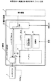
図2は本発明の一実施の形態例を示すブロック図である。図1と同一のものは、同一の符号を付して示す。図において、電源部2において、13はバッテリー11の充放電を制御するための設定値(パラメータ)を保持するための記録部である。該記録部13には、バッテリー11に充電を行なうための基準値となるバッテリー残量データや、バッテリーの電圧値が保持されている。この記録部13は、外部から設定値を変更することができるようになっている。
【0021】
10はACアダプタ識別部、11はバッテリー、12はバッテリー状態監視部、13は電源切換部である。ACアダプタ識別部10は、ACアダプタ出力を監視しており、出力電圧を監視することによりACアダプタ1が接続されたかどうかを識別するようにしている。例えばACアダプタ1が接続されたらその出力電圧は16V、接続されていない場合には0Vというように出力電圧が変化するので、この変化をとらえることにより、ACアダプタ1が接続されたかどうかを識別することができる。
【0022】
従って、ACアダプタ識別部10は、ACアダプタ1以外から回路駆動のための電源を供給される必要がある。例えば、バッテリー11から電源を供給されたり、リチウム電池等のボタン電池で動作させたりすることができる。リチウム電池で動作させる場合、容量が限られているため、ACアダプタ識別部10は、低消費電力型の回路とする必要がある。
【0023】
SW1はACアダプタ出力とバッテリー11間に接続されたスイッチである。また、電源切換部13には、ACアダプタ1からの出力か又はバッテリー11の出力を選択して電子機器3に供給するためのスイッチSW2が設けられている。
【0024】
この実施の形態例では、スイッチSW1のオン/オフを制御するための信号とし、ACアダプタ識別部10の出力、バッテリー状態監視部12の出力、外部からの制御信号がそれぞれ用いられるようになっている。また、電源切換部13には、外部からスイッチSW2の状態を切り換える制御信号が入っている。このように構成された装置の動作を説明すれば、以下の通りである。
【0025】
先ず、ACアダプタ10が接続されたものとする。ACアダプタ識別部10はこのことを識別すると、先ず電源切換部13に制御信号を与え、ACアダプタ側を選択させる。この結果、電子機器3にはACアダプタ1からパワーが供給される。それと同時に、ACアダプタ識別部10は、スイッチSW1をオフにする。この結果、バッテリー11にACアダプタ1の出力が接続され、バッテリー11は無負荷状態になる。バッテリー状態監視部12はバッテリー11の状態を監視している。
【0026】
このように構成すれば、ACアダプタ識別部10がACアダプタ1が接続されたことを検出して電源切換部13を制御し、前記バッテリー状態監視部12がバッテリー11の状態を監視して前記スイッチSW1を制御するので、装置の最適な制御が可能になる。
【0027】
また、この構成によれば、ACアダプタ識別部10がACアダプタ1が識別されたことを受けて、スイッチSW1をオフに、電源切換部13のスイッチSW2をACアダプタ出力側に選択する。この結果、電子機器3にはACアダプタ側からパワーが供給され、バッテリー11の放電を防止することができる。
【0028】
ここで、バッテリー状態監視部12が、バッテリー11が十分に充電された状態にある場合には、スイッチSW1をオフ状態を維持する。この結果、バッテリー11には充電されない。これにより、充電する時間及び回数を少なくすることができ、バッテリー11の劣化防止を図ることができる。
【0029】
図2の実施の形態例では、記録部13が設けられている。この記録部13には、バッテリー11の充放電を制御するための設定値(例えばバッテリー残量基準値、出力電圧基準値等)が記録されている。このように記録部13を設けることにより、電源部2は、記録部13に設定されたパラメータを用いてバッテリー11の充放電を制御することができる。
【0030】
また、本発明によれば、ACアダプタ1を使用時、バッテリー11の残量と、前記記録部13に予め設定された値とを比較してバッテリー11を充電するかどうかを決めるようにしている。ここで、バッテリーの残量としては、例えば電荷が用いられる。バッテリー状態監視部12は、バッテリー11にどれだけの電荷が蓄積されているかを認識する。バッテリー状態監視部12は、バッテリー11の電荷量を常時監視しており、バッテリーの電荷が予め記録部13に記録されている電荷基準量を下回った場合には、スイッチSW1をオンにして、ACアダプタ1からバッテリー11を充電するようにする。このように構成すれば、バッテリー11の状態を最適に制御することができる。
【0031】
また、本発明によれば、ACアダプタ1を使用時、バッテリー11の電圧と前記記録部13に予め設定された電圧とを比較し、バッテリー11を充電するかどうかを決めるようにしている。バッテリー状態監視部12は、バッテリー11の出力電圧がどれくらいあるかを常時監視しており、バッテリーの出力電圧が予め記録部13に記録されている基準電圧値を下回った場合には、スイッチSW1をオンにして、ACアダプタ1からバッテリー11を充電するようにする。このように構成すれば、バッテリー11の状態を最適に制御することができる。
【0032】
図2に示す実施の形態例では、記録部13に外部から設定値(パラメータ)を書き込むことができるようになっている。この場合において、設定値を入力する手段としては、例えばキーボード等を用いて、キーボードからバッテリー残量基準値、出力電圧基準値等の充電特性等を入力する。キーボードから入力されたパラメータを保持し続ける被必要があることから、記録部13としては、データの書き込み可能な不揮発性メモリが用いられる。
【0033】
このように構成すれば、後で記録部の設定値を変更することができる。これにより、バッテリーの充放電特性を任意に変更することができ、都合がよい。
【0034】
図2の実施の形態例では、スイッチSW1を制御するのに、外部から制御できるようになっている。この制御信号としては、例えば電子機器3のアプリケーションから制御できるようになっている。電子機器3は、その動作中に電源電圧をモニタする機能を有している。ここで、電源電圧が予め決められた動作電圧から著しく低下している場合には、スイッチSW1をオンにして、ACアダプタ1から充電することができるようになっている。
【0035】
上述の実施の形態例では、電源切換部13としては、電子的に切り換える場合を例にとった。しかしながら、本発明はこれに限るものではなく、外部から強制的にACアダプタ1の出力か、バッテリー11の出力であるかを手操作により切り換えるようにすることができる。このようにすれば、オペレータの選択により電子機器3に供給される電源としてACアダプタ1及びバッテリー11の何れかを用いるかを選択することができる。例えば、ACアダプタ1を接続している場合でも、バッテリー11を選択することができる。この結果、非常事態に対処することができる。
【0036】
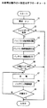
図3は本発明の動作の一例を示すフローチャートである。先ず、電源をオンにする(S1)。ACアダプタ識別部10は、ACアダプタ1が使用されているかどうかをチェックする(S2)。ACアダプタ1が使用されている場合には、電源切換部13を制御してACアダプタ1側を選択し、バッテリーからの電源供給を切り離す(S3)。
【0037】
次に、バッテリー状態監視部12は、記録部13に記録されているバッテリー特性情報を読み出す(S4)。この時、読み出したバッテリー特性情報(ここではバッテリー残量)をAとする。次に、バッテリー状態監視部12は、バッテリー11の残量Bを確認する(S5)。次に、バッテリー状態監視部12は、充電タイミングを判定する(S6)。バッテリー充電のタイミングはA=Bであるかどうかにより判定する。
【0038】
A=Bでなかった場合には、特に処理はしない。A=Bであった場合には、バッテリー残量が減ってきていることになるから、バッテリー状態監視部12は、スイッチSW1をオンにする。この結果、バッテリー11にはACアダプタ1から充電が開始される(S7)。バッテリー状態監視部12はバッテリー残量を確認する(S8)。そして、充電が完了したかどうかをチェックする(S9)。充電が完了しない場合には、ステップS7に戻り充電を続行する。バッテリーの充電が完了した場合には処理を終了する。
【0039】
【発明の効果】
以上説明したように、本発明によれば、以下の効果が得られる。
【0040】
(1)請求項1記載の発明によれば、ACアダプタ識別部がACアダプタが接続されたことを検出して電源切換部を制御し、前記バッテリー状態監視部がバッテリーの状態を監視してスイッチSW1を制御するので、装置の最適な制御が可能になる。
【0041】
(2)請求項2記載の発明によれば、ACアダプタ識別部がACアダプタが識別されたことを受けて、スイッチSW1をオフに、電源切換部のスイッチSW2をACアダプタ出力側に選択する。この結果、電子機器3にはACアダプタ側からパワーが供給され、バッテリーの放電を防止することができる。
【0042】
(3)請求項3記載の発明によれば、ACアダプタがオフになったら、即座にバッテリーから電子機器にパワーを供給することができるようになる。
【0043】
(4)請求項4記載の発明によれば、バッテリーにはACアダプタの出力が入力され、充電される。バッテリー状態監視部は、バッテリーの状態が十分に充電された状態になったら、スイッチSW1をオフにする。このようにすることで、バッテリーの充放電回数を少なくできるので、バッテリーの劣化防止を図ることができる。
【0044】
(5)請求項5記載の発明によれば、記録部に設定された各種のパラメータを用いてバッテリーの充放電を最適に制御することができる。
【0045】
(6)請求項6記載の発明によれば、バッテリーの状態を最適に制御することができる。
【0046】
(7)請求項7記載の発明によれば、バッテリーの状態を最適に制御することができる。
【0047】
(8)請求項8記載の発明によれば、後で記録部の設定値を変更することができる。これにより、バッテリーの充放電特性を任意に変更することができ、都合がよい。
【0048】
(9)請求項9記載の発明によれば、オペレータの選択により電子機器3に供給される電源としてACアダプタ1及びバッテリーの何れかを用いるかを選択することができる。例えば、ACアダプタを接続している場合でも、バッテリーを選択することができる。この結果、非常事態に対処することができる。
【0049】
このように、本発明によれば、バッテリーの劣化防止を図ることができるバッテリー充放電制御装置を提供することができる。
【図面の簡単な説明】
【図1】本発明の原理ブロック図である。
【図2】本発明の一実施の形態例を示すブロック図である。
【図3】本発明の動作の一例を示すフローチャートである。
【符号の説明】
1 ACアダプタ
2 電源部
3 電子機器
10 ACアダプタ識別部
11 バッテリー
12 バッテリー状態監視部
13 電源切換部
SW1 スイッチ
SW2 スイッチ[0001]
TECHNICAL FIELD OF THE INVENTION
The present invention relates to a battery charge / discharge control device, and more particularly, to an electronic device using a battery and an AC adapter, in which the charge / discharge of the battery is controlled by the remaining amount or voltage of the battery to reduce the deterioration of the battery. And a charge / discharge control device.
[0002]
[Prior art]
In an electronic device that operates using a rechargeable battery or an AC adapter, the battery is charged regardless of the remaining amount of the battery even when the AC adapter is used.
[0003]
As this kind of conventional technology, there is a technology in which a built-in secondary battery can be appropriately charged according to a use situation or an operation situation so as not to cause overcharging (for example, see Patent Document 1).
[0004]
[Patent Document 1]
JP-A-8-186942 (
[0005]
[Problems to be solved by the invention]
In the above-described prior art, charging of the battery is controlled under certain conditions so that the built-in secondary battery (battery) does not overcharge. However, the characteristics of a battery deteriorate when it is repeatedly charged and discharged. However, in the related art, no consideration has been given to prevention of deterioration of the characteristics of the battery due to repeated charging and discharging.
[0006]
The present invention has been made in view of such a problem, and has as its object to provide a battery charge / discharge control device capable of preventing battery deterioration.
[0007]
[Means for Solving the Problems]
(1) The invention described in
[0008]
In the
[0009]
A power supply switching unit 13 receives the output of the
[0010]
With this configuration, the AC adapter identification unit 10 detects that the
(2) In the invention described in
[0011]
With this configuration, the AC adapter identification unit 10 turns off the switch SW1 and selects the switch SW2 of the power supply switching unit 13 on the AC adapter output side in response to the identification of the
(3) The invention according to
[0012]
With this configuration, when the
(4) The invention according to claim 4 is characterized in that the battery
[0013]
The output of the AC adapter 10 is input to the battery 11 and charged. When the state of the battery becomes sufficiently charged, the battery
(5) The invention according to claim 5 is characterized in that a recording unit for holding a set value for controlling charging / discharging of the battery is provided.
[0014]
With this configuration, it is possible to optimally control the charging and discharging of the battery 11 using various parameters set in the recording unit.
(6) The invention according to claim 6 is characterized in that when the AC adapter is used, the remaining amount of the battery is compared with a value preset in the recording unit to determine whether to charge the battery. And
[0015]
Here, for example, electric charge is used as the remaining amount of the battery. The battery
(7) The invention according to claim 7 is characterized in that, when the AC adapter is used, the voltage of the battery is compared with a voltage preset in the recording unit to determine whether to charge the battery. .
[0016]
With this configuration, the state of the battery 11 can be optimally controlled.
(8) The invention according to
[0017]
With this configuration, the setting value of the recording unit can be changed later. This makes it possible to arbitrarily change the charge / discharge characteristics of the battery, which is convenient.
(9) The invention according to claim 9 is characterized in that power is supplied to the electronic device from the battery even when the AC adapter is available by controlling the power supply switching unit from the outside.
[0018]
With this configuration, it is possible to select which of the
[0019]
BEST MODE FOR CARRYING OUT THE INVENTION
Hereinafter, embodiments of the present invention will be described in detail with reference to the drawings.
[0020]
FIG. 2 is a block diagram showing one embodiment of the present invention. 1 are denoted by the same reference numerals. In the figure, in a
[0021]
Reference numeral 10 denotes an AC adapter identification unit, 11 denotes a battery, 12 denotes a battery state monitoring unit, and 13 denotes a power switching unit. The AC adapter identification unit 10 monitors the output of the AC adapter, and monitors the output voltage to identify whether the
[0022]
Therefore, the AC adapter identification unit 10 needs to be supplied with power for circuit driving from a source other than the
[0023]
SW1 is a switch connected between the output of the AC adapter and the battery 11. Further, the power supply switching unit 13 is provided with a switch SW2 for selecting an output from the
[0024]
In this embodiment, an output of the AC adapter identification unit 10, an output of the battery
[0025]
First, it is assumed that the AC adapter 10 is connected. Upon identifying this, the AC adapter identification unit 10 first supplies a control signal to the power supply switching unit 13 to select the AC adapter side. As a result, power is supplied to the
[0026]
With this configuration, the AC adapter identification unit 10 detects that the
[0027]
Further, according to this configuration, in response to the
[0028]
Here, when the battery 11 is in a fully charged state, the battery
[0029]
In the embodiment of FIG. 2, a recording unit 13 is provided. In the recording unit 13, set values (for example, a reference value of a remaining battery level, a reference value of an output voltage, and the like) for controlling charging and discharging of the battery 11 are recorded. By providing the recording unit 13 in this manner, the
[0030]
According to the present invention, when the
[0031]
Further, according to the present invention, when the
[0032]
In the embodiment shown in FIG. 2, setting values (parameters) can be written to the recording unit 13 from outside. In this case, as a means for inputting a set value, for example, a keyboard or the like is used to input a charge characteristic such as a battery remaining amount reference value and an output voltage reference value from the keyboard. Since it is necessary to keep holding the parameters input from the keyboard, a non-volatile memory in which data can be written is used as the recording unit 13.
[0033]
With this configuration, the setting value of the recording unit can be changed later. This makes it possible to arbitrarily change the charge / discharge characteristics of the battery, which is convenient.
[0034]
In the embodiment of FIG. 2, the switch SW1 can be controlled externally to control the switch SW1. The control signal can be controlled from, for example, an application of the
[0035]
In the above-described embodiment, the power supply switching unit 13 is electronically switched. However, the present invention is not limited to this, and it is possible to manually switch between the output of the
[0036]
FIG. 3 is a flowchart showing an example of the operation of the present invention. First, the power is turned on (S1). The AC adapter identification unit 10 checks whether the
[0037]
Next, the battery
[0038]
If A = B is not satisfied, no particular processing is performed. If A = B, it means that the remaining battery level is decreasing, and the battery
[0039]
【The invention's effect】
As described above, according to the present invention, the following effects can be obtained.
[0040]
(1) According to the first aspect of the present invention, the AC adapter identification unit detects that the AC adapter is connected and controls the power supply switching unit, and the battery state monitoring unit monitors the state of the battery and switches the power supply. Since the SW1 is controlled, the apparatus can be optimally controlled.
[0041]
(2) According to the second aspect of the invention, when the AC adapter is identified, the AC adapter identification unit turns off the switch SW1 and selects the switch SW2 of the power supply switching unit on the AC adapter output side. As a result, power is supplied to the
[0042]
(3) According to the third aspect of the invention, when the AC adapter is turned off, power can be immediately supplied from the battery to the electronic device.
[0043]
(4) According to the fourth aspect of the invention, the output of the AC adapter is input to the battery and charged. The battery state monitoring unit turns off the switch SW1 when the state of the battery is sufficiently charged. By doing so, the number of times of charging and discharging of the battery can be reduced, so that deterioration of the battery can be prevented.
[0044]
(5) According to the fifth aspect of the invention, it is possible to optimally control the charging and discharging of the battery using various parameters set in the recording unit.
[0045]
(6) According to the invention described in claim 6, the state of the battery can be optimally controlled.
[0046]
(7) According to the invention described in claim 7, the state of the battery can be optimally controlled.
[0047]
(8) According to the eighth aspect of the invention, it is possible to change the set value of the recording unit later. This makes it possible to arbitrarily change the charge / discharge characteristics of the battery, which is convenient.
[0048]
(9) According to the ninth aspect, it is possible to select which of the
[0049]
Thus, according to the present invention, it is possible to provide a battery charge / discharge control device capable of preventing battery deterioration.
[Brief description of the drawings]
FIG. 1 is a principle block diagram of the present invention.
FIG. 2 is a block diagram showing an embodiment of the present invention.
FIG. 3 is a flowchart showing an example of the operation of the present invention.
[Explanation of symbols]
DESCRIPTION OF
Claims (9)
バッテリーにACアダプタの出力を接続するスイッチと、
ACアダプタが接続されたことを識別し、識別結果に応じて前記電源切換部及びスイッチのオン/オフを制御するACアダプタ識別部と、
前記バッテリーの状態を監視して、前記スイッチのオン/オフを制御するバッテリー状態監視部と、
を設けたことを特徴とするバッテリー充放電制御装置。In an apparatus configured to supply power by selecting either an AC adapter or a battery by a power supply switching unit to an electronic device,
A switch for connecting the output of the AC adapter to the battery,
An AC adapter identification unit that identifies that an AC adapter has been connected, and controls on / off of the power supply switching unit and the switch according to the identification result;
A battery state monitoring unit that monitors the state of the battery and controls on / off of the switch;
A battery charge / discharge control device comprising:
Priority Applications (1)
| Application Number | Priority Date | Filing Date | Title |
|---|---|---|---|
| JP2003021535A JP2004236426A (en) | 2003-01-30 | 2003-01-30 | Battery charging/discharging control device |
Applications Claiming Priority (1)
| Application Number | Priority Date | Filing Date | Title |
|---|---|---|---|
| JP2003021535A JP2004236426A (en) | 2003-01-30 | 2003-01-30 | Battery charging/discharging control device |
Publications (1)
| Publication Number | Publication Date |
|---|---|
| JP2004236426A true JP2004236426A (en) | 2004-08-19 |
Family
ID=32950841
Family Applications (1)
| Application Number | Title | Priority Date | Filing Date |
|---|---|---|---|
| JP2003021535A Pending JP2004236426A (en) | 2003-01-30 | 2003-01-30 | Battery charging/discharging control device |
Country Status (1)
| Country | Link |
|---|---|
| JP (1) | JP2004236426A (en) |
Cited By (5)
| Publication number | Priority date | Publication date | Assignee | Title |
|---|---|---|---|---|
| JP2007325390A (en) * | 2006-05-31 | 2007-12-13 | Victor Co Of Japan Ltd | Charging device |
| JP2012010441A (en) * | 2010-06-22 | 2012-01-12 | Nec Aerospace Syst Ltd | Portable terminal |
| WO2018012055A1 (en) | 2016-07-13 | 2018-01-18 | ソニーモバイルコミュニケーションズ株式会社 | Information processing device, information processing system, and charging method |
| KR20180134633A (en) * | 2017-06-09 | 2018-12-19 | 오씨아이 주식회사 | System for management state of charge of energy storage device |
| CN110931902A (en) * | 2020-02-19 | 2020-03-27 | 深圳奥特迅电力设备股份有限公司 | Storage battery pack online maintenance method and system |
-
2003
- 2003-01-30 JP JP2003021535A patent/JP2004236426A/en active Pending
Cited By (8)
| Publication number | Priority date | Publication date | Assignee | Title |
|---|---|---|---|---|
| JP2007325390A (en) * | 2006-05-31 | 2007-12-13 | Victor Co Of Japan Ltd | Charging device |
| JP2012010441A (en) * | 2010-06-22 | 2012-01-12 | Nec Aerospace Syst Ltd | Portable terminal |
| WO2018012055A1 (en) | 2016-07-13 | 2018-01-18 | ソニーモバイルコミュニケーションズ株式会社 | Information processing device, information processing system, and charging method |
| US11336107B2 (en) | 2016-07-13 | 2022-05-17 | Sony Corporation | Information processing device, information processing system, and charging method |
| KR20180134633A (en) * | 2017-06-09 | 2018-12-19 | 오씨아이 주식회사 | System for management state of charge of energy storage device |
| KR102357402B1 (en) | 2017-06-09 | 2022-01-28 | 오씨아이 주식회사 | System for management state of charge of energy storage device |
| CN110931902A (en) * | 2020-02-19 | 2020-03-27 | 深圳奥特迅电力设备股份有限公司 | Storage battery pack online maintenance method and system |
| CN110931902B (en) * | 2020-02-19 | 2020-07-31 | 深圳奥特迅电力设备股份有限公司 | Storage battery pack online maintenance method and system |
Similar Documents
| Publication | Publication Date | Title |
|---|---|---|
| JP2001190032A (en) | Power supply control circuit and power supply control method | |
| JPH09103033A (en) | Charger and charging method | |
| JP2005073434A (en) | Charger | |
| JP2001283934A (en) | Battery pack idetifying device and battery pack | |
| US4631468A (en) | Battery charging circuit for electronic apparatus | |
| US7457141B2 (en) | AC adaptor | |
| JP2004236426A (en) | Battery charging/discharging control device | |
| JP2003235178A (en) | Battery output controller | |
| JP2000261975A (en) | Operation mode control method, operation mode control device and recording medium in which operation mode control process program is recorder for battery-driven apparatus | |
| JP3470768B2 (en) | Charge / discharge device | |
| JP2002010508A (en) | Apparatus and method for charging | |
| JPH114549A (en) | Battery charger | |
| JP2003299257A (en) | Charger | |
| JPH09233727A (en) | Battery charger | |
| JP2003339127A (en) | Uninterruptible power supply | |
| JP2004234540A (en) | Power source selection circuit and portable equipment | |
| JP4189987B2 (en) | Battery pack and external host device system using the battery pack as a power source | |
| JP3496312B2 (en) | Charging device | |
| JP3812210B2 (en) | Control unit for battery pack with built-in microcomputer | |
| JP7278906B2 (en) | Power supply control circuit for electronic equipment | |
| JPH02193534A (en) | Charging and discharging control mechanism | |
| JP2004023975A (en) | Power supply device | |
| JP2000278877A (en) | Information processor provided with function to charge secondary battery | |
| JPH0799730A (en) | Charging/discharging apparatus | |
| JP3018079B2 (en) | Battery power charging controller |