JP3977090B2 - Data processing device - Google Patents
Data processing device Download PDFInfo
- Publication number
- JP3977090B2 JP3977090B2 JP2002025417A JP2002025417A JP3977090B2 JP 3977090 B2 JP3977090 B2 JP 3977090B2 JP 2002025417 A JP2002025417 A JP 2002025417A JP 2002025417 A JP2002025417 A JP 2002025417A JP 3977090 B2 JP3977090 B2 JP 3977090B2
- Authority
- JP
- Japan
- Prior art keywords
- image data
- moving image
- file
- image file
- received
- Prior art date
- Legal status (The legal status is an assumption and is not a legal conclusion. Google has not performed a legal analysis and makes no representation as to the accuracy of the status listed.)
- Expired - Fee Related
Links
Images


Classifications
-
- H—ELECTRICITY
- H04—ELECTRIC COMMUNICATION TECHNIQUE
- H04N—PICTORIAL COMMUNICATION, e.g. TELEVISION
- H04N5/00—Details of television systems
- H04N5/76—Television signal recording
- H04N5/765—Interface circuits between an apparatus for recording and another apparatus
- H04N5/77—Interface circuits between an apparatus for recording and another apparatus between a recording apparatus and a television camera
- H04N5/772—Interface circuits between an apparatus for recording and another apparatus between a recording apparatus and a television camera the recording apparatus and the television camera being placed in the same enclosure
-
- H—ELECTRICITY
- H04—ELECTRIC COMMUNICATION TECHNIQUE
- H04N—PICTORIAL COMMUNICATION, e.g. TELEVISION
- H04N5/00—Details of television systems
- H04N5/76—Television signal recording
- H04N5/765—Interface circuits between an apparatus for recording and another apparatus
-
- H—ELECTRICITY
- H04—ELECTRIC COMMUNICATION TECHNIQUE
- H04N—PICTORIAL COMMUNICATION, e.g. TELEVISION
- H04N5/00—Details of television systems
- H04N5/76—Television signal recording
- H04N5/84—Television signal recording using optical recording
- H04N5/85—Television signal recording using optical recording on discs or drums
-
- H—ELECTRICITY
- H04—ELECTRIC COMMUNICATION TECHNIQUE
- H04N—PICTORIAL COMMUNICATION, e.g. TELEVISION
- H04N9/00—Details of colour television systems
- H04N9/79—Processing of colour television signals in connection with recording
- H04N9/80—Transformation of the television signal for recording, e.g. modulation, frequency changing; Inverse transformation for playback
- H04N9/804—Transformation of the television signal for recording, e.g. modulation, frequency changing; Inverse transformation for playback involving pulse code modulation of the colour picture signal components
- H04N9/8042—Transformation of the television signal for recording, e.g. modulation, frequency changing; Inverse transformation for playback involving pulse code modulation of the colour picture signal components involving data reduction
Description
【0001】
【発明の属する技術分野】
本発明はデータ処理装置に関し、特には情報データの通信処理に関する。
【0002】
【従来の技術】
近年、デジタルカメラやデジタルビデオカメラなど動画像や静止画像のデジタル画像データを記録する機器の普及が進んでいる。
【0003】
デジタルカメラでは記録媒体として小型メモリカードが広く利用されており、静止画像データだけでなく動画像データも記録できるものも登場している。
【0004】
また、デジタルビデオカメラでは記録媒体としてテープが広く利用されている。更に、記録媒体としてテープだけでなく小型メモリカードや光磁気ディスクのようなランダムアクセス可能な記録媒体を使用するものが登場してきており、動画像データだけでなく静止画像データも記録可能になってきている。このようなランダムアクセス可能な記録媒体を使用するデジタルビデオカメラでは、画像データをファイルの形式で保存する構成となる。
【0005】
これらの機器は、他の機器とケーブルで接続して画像データを転送することが一般的に行われるようになっており、特にデジタルビデオカメラでは、IEEE1394インターフェイスというデータ転送フォーマットが広く利用されている。
【0006】
IEEE1394インターフェイスは、転送モードとして非同期データを転送するAsynchronous転送モード(非同期転送モード)と、リアルタイムなビデオストリームデータ等の同期データを転送するIsochronous転送モード(同期転送モード)があるのが特徴的である。
【0007】
Isochronous転送モードは所定量のデータを一定データレートで連続的に転送することが要求されるデータ、特に動画像ストリームの転送に有効である。例えば、デジタルビデオカメラとパーソナルコンピュータ(以下PC)をIEEE1394インターフェイスで接続した場合に、Isochronous転送モードを利用することによって、デジタルビデオカメラからPCに転送されてくる画像データをPCでデコード処理してPCのモニタにリアルタイムに表示することが可能となる。
【0008】
一方、Asynchronous転送モードは、指定したノードに対して非同期に転送することが要求されるデータ、例えば制御コマンドやファイルデータなどの転送に有効である。更に、Asycrhonous転送モードでは、受信操作が行われたことを応答することができ、Isochoronous転送モードより確実な通信を行うことができる。
現在、デジタルビデオカメラでIEEE1394インターフェイスを使用して画像データを送受信する場合には、Isochoronous転送モードを使用して転送するのが一般的である。例えば、デジタルビデオカメラとPCをIEEE1394インターフェイスで接続した場合に、Isochronous転送モードを利用してデジタルビデオカメラからPCに送信されてくる画像データを、PCでデコード処理してリアルタイムに表示するアプリケーションソフトなどが広く普及している。さらに、Isochronous転送モードでPCに送信されてくる画像データを、ユーザの指示によってPCのハードディスクに保存していくことで、動画像データファイルを作成する処理を行うアプリケーションソフトもある。
【0009】
また、デジタルビデオカメラ二台をIEEE1394インターフェイスで接続し、Isochronous転送モードを使用して画像データのダビングを行うことも一般的に行われている。
【0010】
【発明が解決しようとする課題】
しかしながら、リアルタイム転送モードで転送された画像データストリームを記録媒体に記録する場合、送信側となる機器が記録媒体に保持している画像データと、画像受信側となる機器が保存する画像データが、完全に一致しない可能性があるという問題がある。
【0011】
例えば、記録媒体上の画像データを画像データファイルとして取り扱うデジタルビデオカメラとPCをIEEE1394インターフェイスで接続し、ビデオカメラからIshochronous転送モードで送信した画像データをPCにおいてファイルとして保存する場合、PCに保存される画像データはPCで保存開始の指示を操作したところからの画像データとなり、動画像データの先頭部分や終了部分が完全には一致しない可能性が生じる。
【0012】
これはPCで保存される画像データファイルは、デジタルビデオカメラの記録媒体上にあった元の画像データファイルとは異なった画像データファイルになることを意味している。
【0013】
また、Isochronous転送モードはリアルタイム性を持った転送モードであるので、動画像データやオーディオデータのような時間に関連する情報をもったデータを転送するのに適しているが、静止画像データを転送するのには適していない。
【0014】
例えば、Isochronous転送モードを用いて静止画像データを送信する場合、静止画像データを動画像データに従うフォーマットに変換してから転送することになる。そのため、受信側では元の画像データとは異なった画像データを受信することとなる。
【0015】
また、動画像データを転送する場合でも、機器によってIsochronous転送モードで転送することができる画像データのフォーマットは限られているので、送信すべき画像データのフォーマットを送信可能なフォーマットに変換して送信しなければならないといった状況が考えられる。
【0016】
このように、Isochronous転送モードのようなリアルタイムの転送方式により画像データを連続したストリームとして送信する場合、元の画像データとは異なった形態の画像データを転送する可能性が生じる。これはデジタルビデオカメラとPCを接続した場合だけでなく、リアルタイムの転送方式を使用して画像データをやり取りする場合全てに生じる可能性があることである。
【0017】
そして、リアルタイムの転送方式を利用して画像データを受信して保存しようとした場合、元の画像データファイルとは異なった画像データファイルを保存することになる。これは、ユーザが意図している画像データファイルの保存とは異なってしまう可能性があり、混乱の原因となる。
【0018】
本発明は前述の如き問題を解決することを目的とする。
【0019】
本発明の他の目的は、簡単な操作にて元の画像データと同じ形式で転送された画像データのファイルを受信可能とする処にある。
【0020】
【課題を解決するための手段】
前記目的を達成するため、本発明によれば、外部送信装置より送信された動画像ファイル及び前記動画像ファイルに含まれる前記動画像データを受信する通信手段と、指示手段と、前記通信手段による前記動画像データの受信中における前記指示手段の指示に応じて前記受信中の動画像データを含む動画像ファイルの送信を前記外部送信装置に要求すると共に、前記送信要求に応じて前記外部送信装置より送信された動画像ファイルを受信するよう前記通信手段を制御する制御手段と、前記受信された動画像ファイルを記録媒体に記録する記録手段とを備えるデータ処理装置が提示される。
【0021】
【発明の実施の形態】
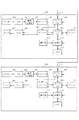
図1は、本発明に係るデジタルビデオカメラから構成されるシステムの構成を示すブロック図である。本実施形態の画像記録再生システムは、図1に示すように、同じ構成のデジタルビデオカメラ100と200とをデジタルインターフェイスで接続した例である。このデジタルビデオカメラ100及びデジタルビデオカメラ200は、それぞれ同様の機能を持ち、更に、デジタルインターフェイスによる画像送信機能と画像受信機能の両方の機能を持つ。
【0022】
以下、デジタルビデオカメラ100が受信側装置、デジタルビデオカメラ200が送信側装置として機能する場合について説明する。
【0023】
また、本実施形態では、デジタルインターフェイスとしてIEEE1394を用い、制御コマンドを送受信するためのプロトコルとしてFCP(Function Control Protocol)を使用する。FCPでは、Asynchronous転送モードにより種々のコマンドデータ及びレスポンスデータを送信する。
【0024】
デジタルビデオカメラ100は、Isochronous転送モードで受信している画像データの元となる画像データファイルを取得するためのカレントファイル取得コマンドを画像送信装置に送信する機能を持つ。
【0025】
また、デジタルビデオカメラ200は、カレントファイル取得コマンドを受信して、Isochronous転送モードで送信している画像データを含むファイルをAsynchronous転送モードで送信する機能を持つ。
【0026】
図1のデジタルビデオカメラ100において、101は被写体の光学像を電気信号に変換するカメラ部である。102は、A/D変換器である。103は、デジタル化された画像データを所定のフォーマットのデジタル画像データに変換する画像処理部である。104は、デジタル画像データを所定の符号化方式に従い符号化してその情報量を圧縮するエンコーダである。本形態ではMPEG2方式に従い画像データを符号化する。
【0027】
105はディスクD1に対して画像データを記録再生するディスクI/Fである。106はデジタルインターフェイス(以下DIF)であり、本形態ではIEEE1394インターフェイスを用いる。D1はDVD−RAMやMOなど、ランダムアクセス可能なディスク状記録媒体であり、動画像データや静止画像データ、音声データなどのデジタルデータをデータファイルとして記録可能である。
【0028】
107は符号化されたデジタルデータを復号する機能を持つデコーダである。108はD/A変換機、109は表示部であるモニタである。110はビデオカメラ100の動作を制御する制御部であり、マイクロコンピュータを有する。1111は書き込み可能なメモリであり、制御部110の読み取り可能なプログラムコードなどを記憶する。112は操作パネルやリモコンなどからなる操作部である。113はDIF106と外部機器のIEEE1394インターフェイスを接続する端子である。
【0029】
なお、図1のビデオカメラ200もビデオカメラ100同様の構成となっているので、ビデオカメラ200の各部の詳細な説明は省略する。
【0030】
次に、図1のビデオカメラ100及び、ビデオカメラ200の動作について説明する。
【0031】
ビデオカメラ100及びビデオカメラ200は、それぞれディスクD1とD2に記録されている画像データを再生する再生モードと、カメラ部により得られた画像データまたはDIFから入力される画像データを画像データファイルとしてディスクに記録する記録モードとを有する。
【0032】
また、各ビデオカメラ100及び200の制御部は、再生モード時は画像送信機能を持ち、記録モード時は画像受信機能を持つよう、各DIFの機能を制御する。以下、ビデオカメラ100が記録モードで動作しており、ビデオカメラ200が再生モードで動作している例を説明する。
【0033】
まず、ビデオカメラ100の記録モードの動作について説明する。
【0034】
カメラ部101は被写体の光学像を電気信号に変換し、その電気信号をA/D変換器102に供給する。A/D変換器102はカメラ部101から受け取った電気信号をデジタル化する。画像処理部103はデジタル化された画像データを所定のフォーマットのデジタル画像データに変換し、その変換した画像データをエンコーダ104とD/A変換器108に送る。エンコーダ104はデジタル化された画像データを符号化し、ディスクI/F105に渡す。
【0035】
記録モードにおいては、DIF106はIsochronous転送モードで画像データを受信することができる。DIF106はIsochronous転送モードで画像データを受け取った場合は、その画像データをデコーダ107に送信し、また、Isochronous転送モードで画像データを受信していることを制御部110に知らせる。
【0036】
更に、DIF106は制御部110の指示に従い、端子113を介して接続されたIEEE1394シリアルバス上の他のノード(機器)に対して制御コマンドを送信することも可能である。この制御コマンドのひとつである、Isochronous転送モードで受信している画像データのファイルをAsynchronous転送モードで取得するためのカレントファイル取得コマンドを発行して、画像データファイルをAsynchronous転送モードで受信することもできる。Asynchronous転送モードで受信した画像データファイルは、ディスクI/F105に送られる。
【0037】
操作部112はユーザによるカメラ部101からの画像データの記録や停止などの操作に応じて制御部110に操作指示を送る。例えば、操作部112はユーザによって記録操作が行われた場合は、制御部110に記録指示を送る。また、停止操作が行われた場合には、制御部110に停止命令を送る。
【0038】
制御部110は操作部112からの指示に従い、ディスクI/F105による記録再生動作を制御すると共に、DIF106に対して制御コマンドの送信指示その他の指示を行う。
【0039】
操作部112からの記録指示の際にIsochronous転送モードで画像データを受信していなかった場合、制御部110はディスクI/F105に対してエンコーダ104からの画像データを記録するよう制御する。また、制御部110は操作部112からの停止指示に応じて、ディスクI/F105に記録停止命令を送る。
【0040】
ディスクI/F105は周知のレーザピックアップや磁気ヘッド、及びディスクD1を回転駆動するためのメカニズムなどを有し、制御部110から記録指示を受けると、その時点でエンコーダ104から出力されている画像データをディスクD1上に記録する。本形態では、記録開始から記録停止までの間にディスクD1に記録された一連の動画像データを一つの動画像ファイルとしてディスクD1に記録する。
【0041】
また、制御部110は、DIF106によるIsochronous転送モードでの画像データの受信中において、ユーザが操作部112のキーを操作することによりファイル記録の指示があると、DIF106に対してカレントファイル取得コマンドの送信を指示する。DIF106は制御部110からの指示に従い、現在Isochronous転送モードで受信している画像データを含むファイルをAsynchronous転送モードで送信するよう外部機器に要求するためのカレントファイル取得コマンドを生成し、送信側装置であるビデオカメラ200に出力する。
【0042】
送信側装置であるビデオカメラ200は、このカレントファイル送信コマンドに応じて、後述の如く現在Isochronous転送モードにて送信中の画像データを含む画像ファイルをディスクD2より再生し、Asynchronous転送モードにてビデオカメラ100のDIF106に対して送信する。
【0043】
ディスクI/F105は、このようにDIF106がAsynchronous転送モードで受信した画像データファイルを取得した場合は、ディスクD1に対しこの画像データファイルを記録する。また、ディスクI/F105はエンコーダ104からの画像データを記録している時に制御部110から停止指示を受けると、ディスクD1に対する画像データの記録を停止する。
【0044】
記録モードにおいてはDIF106によりIsochronous転送モードで受信された動画像データがデコーダ107に出力されており、デコーダ107はDIF106から画像データを受け取ると、その画像データをデコードし、D/A変換器108に出力する。
【0045】
D/A変換器108は受信したデータをアナログ信号に変換する。画像処理部103とデコーダ107の両方から画像データを受け取っている場合は、デコーダ107から送られてくる画像データを優先して処理する。
【0046】
モニタ109はD/A変換器108から供給されたアナログ画像信号に係る画像を表示する。
【0047】
このような構成とすることで、ビデオカメラ100は、Isochronous転送モードで受信中の画像データをファイルとして記録することができる。
【0048】
ここで、ビデオカメラ100の画像データ保存処理について、図2のフローチャートを用いて詳細に説明する。
【0049】
図2において、ステップS201において、DIF106がIsochronous転送モードで画像データを受信している場合は、受信している画像データをデコーダ107でデコード処理してモニタ109に表示し、また、Isochronous転送モードで画像データを受信していない場合は、カメラ部101で撮影された画像データをモニタ109に表示する。
【0050】
ステップS202は、ユーザから画像データの保存指示があったかどうかの判断処理である。保存指示がなかった場合はステップS201に戻り、画像データの表示処理を繰り返す。保存指示があった場合はステップS203に移行する。
【0051】
ステップS203では、Isochronous転送モードで画像データを受信中かどうか判断し、Isochronous転送モードで画像データを受信している最中に、ユーザから画像データ保存の指示があった場合にはステップS204に移行する。ステップS204では、DIF106を制御し、現在Isochronous転送モードで受信している画像データのファイルを取得するため、カレントファイル取得コマンドを送信する。
【0052】
そして、ステップS205では、ステップS204で送信したカレントファイル取得コマンドの応答として送信側装置よりAsynchronous転送モードで画像データファイルを受信し、ディスクD1に保存する。
【0053】
また、ステップS203において、Isochronous転送モードで画像データを受信していない場合、ステップS206に移行し、カメラ部101で撮影している画像データをディスクD1に保存する。
【0054】
このような処理を行うことで、Isochronous転送モードで受信している画像データの元となる画像データファイルを取得して記録することが可能となる。
【0055】
次に、ビデオカメラ200による再生モードの動作について説明する。
【0056】
ビデオカメラ200は、再生モードにおいて、ディスクD2に記録されている画像データをディスクI/F205により再生し、DIF206によりIsochronous転送モードでビデオカメラ100に送信することができる。また、DIF206は他のノードから送信されてくる制御コマンドも受信する。DIF206は制御コマンドを受け取った場合、そのコマンドを制御部210に送信する。
【0057】
ディスクD2には動画像データファイルや、静止画像データファイル、音声データなどのデジタルデータのファイルが記録されている。
【0058】
操作部212はユーザの操作に従い再生や停止などの操作指示を制御部210に送る。例えば、操作部212は、ユーザによって再生操作が行われた場合は制御部210に再生指示を送信する。また、停止操作が行われた場合には制御部210に停止命令を送信する。
【0059】
制御部210は操作部212からの指示やDIF206からの制御コマンドを受信し、ディスクI/F205の動作を制御すると共に、DIF206によるデータの転送処理を制御する。
【0060】
制御部210は操作部212から再生指示があると、ディスクI/F205に画像データの再生を指示する。ディスクI/F205は制御部210からの指示に従い、ディスクD2に記録されている画像データを再生し、デコーダ207及びDIF206に出力する。ここで、制御部210は、画像データをディスクD2より再生する際、現在再生中の画像ファイルを特定するためのファイルパス名情報を保持している。
【0061】
再生された画像データはデコーダ207によりデコードされ、D/A変換器208を介してモニタ209にて表示される。また、制御部210はDIF206を制御し、再生された画像データをIsochronous転送モードにてビデオカメラ100に送信する。
【0062】
また、制御部210はDIF206を介して、前述のようにカレントファイル取得コマンドが送られてくると、記憶しておいた現在再生中の画像ファイルのファイルパス名と共に、ディスクI/F205に対して現在再生中の画像データを含む画像ファイルの再生を指示する。
【0063】
ディスクI/F205は制御部210からカレントファイル送信命令を受け取ると、指定されたファイルパス名の画像データファイルをディスクD2から読み出し、DIF206に出力する。制御部210はDIF206を制御し、この画像データファイルをAsynchronous転送モードでビデオカメラ100に送信する。
【0064】
このように、本形態では、リアルタイム転送モードによる画像データの受信中にユーザが画像データの保存指示を行った場合、その画像データを含む元の画像データファイルの転送を送信元の機器に要求している。そして、送信側機器においてこの要求に従い現在送信中の画像データを含む画像ファイルをファイル転送モードにて送信している。
【0065】
これにより、本形態では、リアルタイム転送モードにて受信中の画像データの元となる画像データファイルを確実に取得できる。そのため、元の画像データと同じ形態の画像データファイルを転送、記録することができ、ユーザの望んでいる画像データファイルを保存することが可能となる。
【0066】
なお、前述の実施形態では、ビデオカメラ100と200との間で一つの画像データファイルを送信する場合について説明したが、例えば、ディスクD2内に記録された複数の画像データファイルをビデオカメラ100に送信する場合にも本発明を適用することができる。
【0067】
以下、このように複数の画像データファイルがディスクD2に記録されている場合の処理について説明する。
【0068】
図3はビデオカメラ100によりディスクD2に記録された複数の画像データファイルを受信する際の制御部110の動作を説明するためのフローチャートである。
【0069】
まず、ステップS301において、ビデオカメラ200によりディスクD2に記録されている画像データファイルのうちの一つをIsochronous転送モードにてビデオカメラ100に転送し、ビデオカメラ100ではこのIsochronous転送モードで送信された画像データを受信し、モニタ109に表示する。
【0070】
この状態で、ステップS302において操作部112による保存の指示の有無を検出し、保存指示があった場合には前述のようにステップS303においてDIF106よりビデオカメラ200に対してカレントファイル取得コマンドを送信する。そして、ステップS304において、ビデオカメラ200より送信された現在受信中の画像データを含む画像データファイルをAsynchronous転送モードにて受信し、ディスクI/F105によりディスクD1に記録する。
【0071】
次に、ステップS305において、DIF106よりビデオカメラ200に対し、ディスクD2に記録されている次の画像データファイルに含まれる画像データの送信を要求するコマンドを出力する。そして、ステップS306おいて操作部112より受信停止の指示がない場合、ステップS301に戻り、ビデオカメラ200より送信された次の画像データファイルに含まれる画像データをIsochronous転送モードで受信する。
【0072】
また、ステップS302において保存指示がない場合、ステップS307において現在受信中の画像データを次の画像データファイルにスキップする指示が操作部112によりなされたか否かを検出し、スキップ要求があった場合にはステップS305に進み、DIF106よりDIF106よりビデオカメラ200に対し、ディスクD2に記録されている次の画像データファイルに含まれる画像データの送信を要求するコマンドを出力する。また、ステップS307でスキップ指示もない場合にはそのままステップS301に戻る。
【0073】
そして、ステップS306にて操作部112より受信停止の指示があると処理を終了する。
【0074】
このように、図3の実施形態によれば、ディスクD2に記録された複数の画像データファイルを受信する際、Isochronous転送モードで現在受信中の画像データの保存指示があると、この受信中の画像データを含む画像データファイルの転送要求を送信側装置に出力してAsynchronous転送モードにてこの画像データファイルを受信するので、元の画像データと同じ形態の画像データファイルを転送、記録することができる。
【0075】
加えて、本形態ではAsynchronous転送モードにて画像データファイルを受信、保存した後、ディスクD2に記録されている次の画像データファイルの再生、送信を要求するコマンドを自動的に出力するので、ディスクD2に記録されている複数の画像データファイルを次々に受信、保存する場合に非常に使い勝手がよい。
【0076】
また、Isochronous転送モードにて受信、表示している画像データの保存が不要であると判断した場合には、スキップ指示を出すだけで自動的に次の画像ファイルに含まれる画像ファイルの送信要求を出力し、Isochronous転送モードにて受信を開始するので、ディスクD2に記録されている複数の画像データファイルを次々に受信する場合にも非常に使い勝手がよい。
【0077】
なお、図1のビデオカメラにおいては、ディスク媒体に対して画像データを記録再生していたが、これ以外の記録媒体、例えばメモリカードなどのランダムアクセス媒体に対して画像データなどの情報データを記録再生する装置に対しても本発明を適用可能であり、同様の効果をもつ。
【0078】
次に、本発明の第2の実施形態について説明する。
【0079】
図4は、本発明に係る記録再生システムの構成を示すブロック図であり、コンピュータ300とビデオカメラ200から構成される。本実施形態においても、コンピュータ300とビデオカメラ200とはIEEE1394インターフェイスにより接続され、制御コマンドを送受信するためのプロトコルとしてFCPを使用する。
【0080】
本形態のコンピュータ300は、Isochronous転送モードで受信している画像データファイルのパス名を取得するためのパス名取得コマンドと、データファイルを取得するためのファイル取得コマンドを送信側装置に送信する機能を持つ。
【0081】
また、本実施形態のビデオカメラ200は前述の実施例で説明した構成及び機能を有し、更に、Isochronous転送モードで送信している画像データファイルのファイルパス名に関するパス名取得コマンドを受信して、画像データファイルのパス名を応答信号として送信する機能と、画像データファイルを取得するためのファイル取得コマンドを受信して、画像データファイルをAsynchronous転送モードで送信する機能を持つ。
【0082】
図4のコンピュータ300において、301はコンピュータ300の動作を制御する演算処理装置(CPU)302はCRTや液晶パネルなどのディスプレイ、303はプログラムデータや動画像データ、静止画像データ、音声データなどのデジタルデータを記録するハードディスク(HDD)である。ハードディスク303には後述する画像データ取得アプリケーションが、CPU301の読み取り可能なプログラムコードとして記録されている。
【0083】
304は内部メモリ、305は符号化された動画像データや静止画像データ、音声データ等を復号するデコーダである。306はキーボードやマウスなどからなる操作部、307は外部装置との間でデジタルデータの送受信を行うデジタルI/Fであり、本形態ではIEEE1394インターフェイスである。308はPCIバスなどのコンピュータ300内部の各処理部を相互に接続するための内部バス、309はDIF307と外部機器とを接続する端子である。
【0084】
図4に示すように、コンピュータ300とビデオカメラ200がIEEE1394インターフェイスによって接続されている。次に、コンピュータ300を構成する各処理部の機能と動作について説明する。本実施形態において、コンピュータ300は、ビデオカメラ200から送信される画像データを受信する画像受信装置として動作する。
【0085】
CPU301はHDD303に記録されているソフトウェアを実行するとともに、さまざまなデータを内部メモリ304に移動させる。また、CPU301は内部バス308によって接続されている各処理部の動作制御なども行う。
【0086】
DIF307はIEEE1394バスを介して転送される画像データを受信することができる。また、DIF307はIEEE1394シリアルバス上の他のノードに対して、制御コマンドを送信することも可能である。
【0087】
ユーザは、操作部306を操作して所望のアプリケーションを選択し、HDD303に記録されているアプリケーションをCPU301に実行させる。この時アプリケーションに関する情報はディスプレイ302によってユーザに提示される。また、ユーザは、操作部306を操作して、このアプリケーションの操作を行うことが可能である。たとえば、ユーザは画像データ取得アプリケーションを実行し、受信している画像データの保存処理の指示を行うことができる。
【0088】
デコーダ305はアプリケーションの動作に基づいて、DIF307から出力された画像データをデコードする。デコードされた画像データは、ディスプレイ302に表示される。なお、デコード処理はHDD303に記録されているアプリケーションが行うような構成でも良い。
【0089】
次に、コンピュータ300がDIF307によりIsochronous転送モードでビデオカメラ200によりディスクD2から再生された画像データを受信している場合の画像データ取得アプリケーションの動作について、図5のフローチャートを用いて詳細に説明する。
【0090】
図5はコンピュータ300におけるCPU301による制御動作を示すフローチャートである。
【0091】
図5において、ステップS501においてIsochronous転送モードで送られてくる画像データを受信し、この受信した画像データをデコーダ305によりデコードしてディスプレイ302に表示する。
【0092】
次に、ステップS502においてユーザから画像データの保存指示があったかどうかの判断し、保存指示がなかった場合はステップS501に戻り、受信している画像データの表示処理を繰り返す。
【0093】
Isochronous転送モードで画像データを受信している最中に、ユーザから画像データ保存の指示があった場合、ステップS503において、CPU301はDIF307を制御し、現在受信している画像データのファイルのパス名を調べるためのパス名取得コマンドをビデオカメラ200に送信する。ビデオカメラ200ではこのパス名取得コマンドに応じて画像データのファイルパス名をコンピュータ300に送信する。ステップS504においてはこのファイルパス名をDIF307により受信する。
【0094】
次に、ステップS505ではIsochronous転送モードで受信している画像データを含む画像データファイルの送信を要求するため、ステップS504で取得したファイルパス名を示す情報を含むファイル取得コマンドをDIF307からビデオカメラ200に送信する。ビデオカメラ200では、後述の如くこのファイル取得コマンドにて指定されたファイルパスの画像データファイルをディスクD2から再生し、Asynchronous転送モードにて送信する。そして、ステップS506において、DIF307によりこのようにAsynchronous転送モードで送信された画像データファイルを受信し、HDD303に保存する。
【0095】
次に、ビデオカメラ200の動作について説明する。
【0096】
通常の記録、再生時の動作は前述の実施形態で説明した通りであり、再生モードにおいてDIF206からIsochronous転送モードにてコンピュータ200に対して画像データを送信する。
【0097】
この状態でコンピュータ200よりDIF206を介してパス名取得コマンドが送られると、制御部210はディスクI/F205に対してパス名の取得指令を出す。ディスクI/F205は制御部210からパス名取得命令を受けると、ディスクD2より画像データを読み出し処理中の場合は、その時読み出している画像データファイルのパス名情報を保持しているので、そのファイルパス名の情報をDIF206によりAsynchronous転送モードでコンピュータ300に送信する。
【0098】
また、コンピュータ200よりDIF206を介してファイル取得コマンドが送られると、制御部210はディスクI/F205に対して画像データファイルの再生命令を出すと共に、DIF206を制御してIsochronous転送モードでのファイルデータ転送を停止する。ディスクI/F205は指定された画像データファイルをディスクD2より再生し、DIF206を制御してこの再生された画像データファイルをAsynchronous転送モードでコンピュータ200に送信する。
【0099】
なお、本実施例では、Asynchronous転送モードでファイル転送を行う場合は、事前にIsochronous転送モードでのデータ転送を停止するような構成としたが、Isochronous転送モードでのデータ転送を停止させないような構成としても良い。
【0100】
このように、本形態においても、コンピュータにおいてリアルタイム転送モードによる画像データの受信中にユーザが画像データの保存指示を行った場合、その画像データを含む元の画像データファイルの転送を送信元の機器に要求している。そして、送信側機器においてこの要求に従い現在送信中の画像データを含む画像ファイルをファイル転送モードにて送信している。
【0101】
これにより、本形態では、リアルタイム転送モードにて受信中の画像データの元となる画像データファイルを確実に取得できる。
【0102】
次に、本発明の第3の実施形態について説明する。
【0103】
本実施形態のシステムの構成は図4に示したものと同様であり、コンピュータ300がDIF307によりIsochronous転送モードで画像データを受信している場合の画像データ取得処理以外は第2の実施形態と同様の処理を行うので、この処理以外の詳細な説明は省略する。
【0104】
コンピュータ300がDIF307によりIsochronous転送モードで画像データを受信している場合の画像データ取得アプリケーションの動作について、図6のフローチャートを用いて詳細に説明する。
【0105】
図6は画像データの受信処理におけるCPU301の制御動作を説明するフローチャートである。
【0106】
図6において、ステップS601〜S604の処理は図5のステップS501〜S504の処理と同様である。
【0107】
次に、ステップS605において、ステップS604で取得したファイルパス名に含まれるファイルの拡張子によって、画像データを含む画像データファイルの形態を検出し、受信方法を判断する。即ち、ファイルの拡張子が静止画を表す拡張子(例えば、jpg、jpeg)だった場合はステップS606に進み、それ以外の拡張子だった場合はステップS608に進む。
【0108】
本形態では、静止画を判断するためのファイル拡張子としてJPEGファイルの例をあげたが、それ以外の拡張子で判断しても良い。また本形態では画像のフォーマットをファイルの拡張子で判断するような構成としたが、その他の方法を用いて判断するような構成でも良い。
【0109】
ステップS605で、Isochronous転送モードで受信している画像データが静止画ファイルのデータであった場合、Isochronous転送モードで受信している画像データを含む画像データファイルの送信を要求するため、ステップS604で取得したファイルパス名を示す情報を含むファイル取得コマンドをDIF307からビデオカメラ200に送信する。ビデオカメラ200ではこのファイル取得コマンドにて指定されたファイルパスの画像データファイルをディスクD2から再生し、Asynchronous転送モードにて送信する。そして、ステップS607において、DIF307によりこのようにAsynchronous転送モードで送信された画像データファイルを受信し、HDD303に保存する。
【0110】
また、Isochronous転送モードで受信している画像データを含む画像データファイルが静止画ファイルでなかった場合、ステップS608においてIsochronous転送モードで受信している画像データを保存する。
【0111】
このように、本形態によれば、リアルタイム転送モードで画像データを受信している場合に、その画像データを含む画像データファイルが動画像データファイルであった場合にはリアルタイム転送モードのままで画像データを取得し、画像データファイルが静止画像データファイルであった場合にはファイル転送モードにてファイルを取得している。
【0112】
そのため、リアルタイム転送モードにて受信している画像データのファイルフォーマットが静止画像データか動画像データかをユーザ自身が区別する必要がなく、いずれのフォーマットの場合であっても同様の操作でユーザの望んでいる画像データを取得することが可能となる。
【0113】
なお、前述の第3の実施形態では、リアルタイム送信されている画像データのフォーマットが静止画ファイルであった場合にその静止画像ファイルをAsynchronous転送モードにて受信しているが、例えば、元の画像ファイルに含まれる画像データのフォーマットが変換されてIsochronous転送モードにて送信されている場合、この受信中の画像データのフォーマットとそのもとの画像データファイルにおけるフォーマットとを比較し、これらが異なる場合に元の画像データファイルをAsynchronous転送モードにて送信するよう要求するよう構成することも可能である。
【0114】
なお、前述の各実施形態においては、画像データの送受信処理について説明したが、例えば、音声データなど他の情報データを送受信する場合にも同様に本発明を適用可能である。
【0115】
また、前述の各実施形態で説明した各機能をコンピュータを使って実現することも可能であり、そのための動作プログラムを記憶した記録媒体も本発明に含まれる。
【0116】
【発明の効果】
本発明によれば、受信中の動画データを含む動画ファイルを取得して記録するので、受信した動画データと同じ形態の動画ファイルを記録することができる。
【図面の簡単な説明】
【図1】本発明が適用されるデータ処理システムの構成を示す図である。
【図2】本発明の実施形態によるデータ受信動作を示すフローチャートである。
【図3】本発明の実施形態によるデータ受信動作を示すフローチャートである。
【図4】本発明が適用されるデータ処理システムの他の構成を示す図である。
【図5】本発明の実施形態によるデータ受信動作を示すフローチャートである。
【図6】本発明の実施形態によるデータ受信動作を示すフローチャートである。[0001]
BACKGROUND OF THE INVENTION
The present invention relates to a data processing apparatus, and more particularly to communication processing of information data.
[0002]
[Prior art]
In recent years, devices such as digital cameras and digital video cameras that record digital image data of moving images and still images have been widely used.
[0003]
In digital cameras, small memory cards are widely used as recording media, and some of them can record not only still image data but also moving image data.
[0004]
Also, tapes are widely used as recording media in digital video cameras. Furthermore, recording media that use not only tape but also randomly accessible recording media such as small memory cards and magneto-optical disks have appeared, and not only moving image data but also still image data can be recorded. ing. A digital video camera that uses such a randomly accessible recording medium is configured to store image data in a file format.
[0005]
These devices are generally connected to other devices with a cable to transfer image data. In particular, a digital video camera uses a data transfer format called IEEE1394 interface widely. .
[0006]
The IEEE 1394 interface is characterized by an asynchronous transfer mode (asynchronous transfer mode) in which asynchronous data is transferred as a transfer mode and an isochronous transfer mode (synchronous transfer mode) in which synchronous data such as real-time video stream data is transferred. .
[0007]
The isochronous transfer mode is effective for transferring a predetermined amount of data that is required to be transferred continuously at a constant data rate, particularly for moving image streams. For example, when a digital video camera and a personal computer (hereinafter referred to as a PC) are connected via an IEEE 1394 interface, by using the isochronous transfer mode, image data transferred from the digital video camera to the PC is decoded and processed by the PC. Can be displayed in real time on the monitor.
[0008]
On the other hand, the Asynchronous transfer mode is effective for transferring data that is requested to be transferred asynchronously to a specified node, such as a control command or file data. Further, in the asycrhonous transfer mode, it is possible to respond that a reception operation has been performed, and more reliable communication can be performed than in the isochoronous transfer mode.
Currently, when image data is transmitted and received using a digital video camera using an IEEE1394 interface, it is generally transferred using an isochoronous transfer mode. For example, when a digital video camera and a PC are connected via an IEEE 1394 interface, application software that decodes the image data transmitted from the digital video camera to the PC using the isochronous transfer mode and displays the data in real time. Is widely spread. In addition, there is application software that performs processing for creating a moving image data file by storing image data transmitted to the PC in the isochronous transfer mode in a hard disk of the PC according to a user instruction.
[0009]
In general, two digital video cameras are connected by an IEEE1394 interface and image data is dubbed using an isochronous transfer mode.
[0010]
[Problems to be solved by the invention]
However, when the image data stream transferred in the real-time transfer mode is recorded on the recording medium, the image data stored in the recording medium by the device on the transmission side and the image data stored by the device on the image reception side are: There is a problem that there is a possibility that they do not match completely.
[0011]
For example, when a digital video camera that handles image data on a recording medium as an image data file is connected to the PC via the IEEE 1394 interface, and image data transmitted from the video camera in the isochronous transfer mode is saved as a file on the PC, the data is saved on the PC. The image data becomes the image data from the operation of the storage start instruction on the PC, and there is a possibility that the head part and the end part of the moving image data do not completely match.
[0012]
This means that the image data file stored on the PC is different from the original image data file on the recording medium of the digital video camera.
[0013]
The isochronous transfer mode is a transfer mode with real-time characteristics, so it is suitable for transferring data with time-related information such as moving image data and audio data, but still image data is transferred. Not suitable for doing.
[0014]
For example, when still image data is transmitted using the isochronous transfer mode, the still image data is transferred after being converted into a format according to the moving image data. For this reason, the receiving side receives image data different from the original image data.
[0015]
Even when moving image data is transferred, the format of image data that can be transferred in the isochronous transfer mode is limited depending on the device. There are situations where you have to do this.
[0016]
As described above, when image data is transmitted as a continuous stream by a real-time transfer method such as the isochronous transfer mode, there is a possibility that image data in a form different from the original image data is transferred. This may occur not only when a digital video camera is connected to a PC but also when image data is exchanged using a real-time transfer method.
[0017]
When image data is received and stored using a real-time transfer method, an image data file different from the original image data file is stored. This may be different from the saving of the image data file intended by the user, which causes confusion.
[0018]
The object of the present invention is to solve the above-mentioned problems.
[0019]
Another object of the present invention is to make it possible to receive a file of image data transferred in the same format as the original image data with a simple operation.
[0020]
[Means for Solving the Problems]
In order to achieve the above object, according to the present invention, a communication unit that receives a moving image file transmitted from an external transmission device and the moving image data included in the moving image file, an instruction unit, and a communication unit In response to an instruction from the instruction means during reception of the moving image data, the external transmission device is requested to transmit a moving image file including the moving image data being received, and the external transmission device is responded to the transmission request. A data processing apparatus is provided that includes control means for controlling the communication means to receive the transmitted moving image file and recording means for recording the received moving image file on a recording medium.
[0021]
DETAILED DESCRIPTION OF THE INVENTION
FIG. 1 is a block diagram showing a configuration of a system including a digital video camera according to the present invention. As shown in FIG. 1, the image recording / playback system of the present embodiment is an example in which
[0022]
Hereinafter, a case where the
[0023]
In this embodiment, IEEE 1394 is used as a digital interface, and FCP (Function Control Protocol) is used as a protocol for transmitting and receiving control commands. In FCP, various command data and response data are transmitted in the Asynchronous transfer mode.
[0024]
The
[0025]
In addition, the
[0026]
In the
[0027]
A disk I /
[0028]
[0029]
Since the
[0030]
Next, operations of the
[0031]
The
[0032]
In addition, the control unit of each
[0033]
First, the operation of the recording mode of the
[0034]
The
[0035]
In the recording mode, the
[0036]
Further, the
[0037]
The operation unit 112 sends an operation instruction to the control unit 110 in response to an operation such as recording or stopping of image data from the
[0038]
In accordance with an instruction from the operation unit 112, the control unit 110 controls the recording / reproducing operation by the disc I /
[0039]
When the image data is not received in the isochronous transfer mode at the time of recording instruction from the operation unit 112, the control unit 110 controls the disk I /
[0040]
The disk I /
[0041]
In addition, when the user operates the keys of the operation unit 112 while the image data is being received in the isochronous transfer mode by the
[0042]
In response to the current file transmission command, the
[0043]
When the
[0044]
In the recording mode, the moving image data received by the
[0045]
The D /
[0046]
The
[0047]
With this configuration, the
[0048]
Here, the image data storage processing of the
[0049]
In FIG. 2, when the
[0050]
Step S202 is processing for determining whether or not there is an instruction to save image data from the user. If there is no save instruction, the process returns to step S201, and the image data display process is repeated. If there is a storage instruction, the process proceeds to step S203.
[0051]
In step S203, it is determined whether image data is being received in the isochronous transfer mode. If image data storage instructions are received from the user while image data is being received in the isochronous transfer mode, the process proceeds to step S204. To do. In step S204, the
[0052]
In step S205, the image data file is received in the asynchronous transfer mode from the transmission side device as a response to the current file acquisition command transmitted in step S204, and stored in the disk D1.
[0053]
If the image data is not received in the isochronous transfer mode in step S203, the process proceeds to step S206, and the image data captured by the
[0054]
By performing such processing, it is possible to acquire and record an image data file that is the source of image data received in the isochronous transfer mode.
[0055]
Next, the operation of the playback mode by the
[0056]
In the playback mode, the
[0057]
The disk D2 records digital data files such as moving image data files, still image data files, and audio data.
[0058]
The
[0059]
The
[0060]
When there is a reproduction instruction from the
[0061]
The reproduced image data is decoded by the
[0062]
When the current file acquisition command is sent via the
[0063]
When the disk I /
[0064]
As described above, in this embodiment, when the user gives an instruction to save image data while receiving the image data in the real-time transfer mode, the transmission source device is requested to transfer the original image data file including the image data. ing. In accordance with this request, the transmitting device transmits an image file including the image data currently being transmitted in the file transfer mode.
[0065]
As a result, in this embodiment, it is possible to reliably acquire the image data file that is the source of the image data being received in the real-time transfer mode. Therefore, an image data file having the same form as the original image data can be transferred and recorded, and an image data file desired by the user can be saved.
[0066]
In the above-described embodiment, the case where one image data file is transmitted between the
[0067]
Hereinafter, processing when a plurality of image data files are recorded on the disk D2 will be described.
[0068]
FIG. 3 is a flowchart for explaining the operation of the control unit 110 when the
[0069]
First, in step S301, one of the image data files recorded on the disk D2 by the
[0070]
In this state, the presence or absence of an instruction for saving by the operation unit 112 is detected in step S302, and if there is a saving instruction, the current file acquisition command is transmitted from the
[0071]
In step S305, the
[0072]
If there is no save instruction in step S302, it is detected in step S307 whether or not an instruction to skip the currently received image data to the next image data file is issued by the operation unit 112, and there is a skip request. In step S305, the
[0073]
Then, when there is an instruction to stop reception from the operation unit 112 in step S306, the process is terminated.
[0074]
As described above, according to the embodiment of FIG. 3, when receiving a plurality of image data files recorded on the disk D2, if there is an instruction to save the image data currently being received in the isochronous transfer mode, Since the transfer request of the image data file including the image data is output to the transmission side device and this image data file is received in the Asynchronous transfer mode, the image data file having the same form as the original image data can be transferred and recorded. it can.
[0075]
In addition, in this embodiment, after the image data file is received and stored in the Asynchronous transfer mode, a command for requesting reproduction and transmission of the next image data file recorded on the disk D2 is automatically output. This is very convenient when a plurality of image data files recorded in D2 are received and stored one after another.
[0076]
Also, if it is determined that it is not necessary to save the image data received and displayed in the isochronous transfer mode, a transmission request for an image file included in the next image file is automatically issued simply by issuing a skip instruction. Since the data is output and reception is started in the isochronous transfer mode, it is very convenient to receive a plurality of image data files recorded on the disk D2 one after another.
[0077]
In the video camera of FIG. 1, image data is recorded and reproduced on a disk medium. However, information data such as image data is recorded on a recording medium other than this, for example, a random access medium such as a memory card. The present invention can be applied to a reproducing apparatus and has the same effect.
[0078]
Next, a second embodiment of the present invention will be described.
[0079]
FIG. 4 is a block diagram showing the configuration of the recording / reproducing system according to the present invention, which is composed of a
[0080]
The
[0081]
In addition, the
[0082]
In the
[0083]
[0084]
As shown in FIG. 4, a
[0085]
The
[0086]
The
[0087]
The user operates the
[0088]
The decoder 305 decodes the image data output from the
[0089]
Next, the operation of the image data acquisition application when the
[0090]
FIG. 5 is a flowchart showing a control operation by the
[0091]
In FIG. 5, the image data sent in the isochronous transfer mode is received in step S501, and the received image data is decoded by the decoder 305 and displayed on the
[0092]
Next, in step S502, it is determined whether or not there is an instruction to save image data from the user. If there is no instruction to save, the process returns to step S501, and the display processing of the received image data is repeated.
[0093]
If the user instructs to save the image data while receiving the image data in the isochronous transfer mode, the
[0094]
In step S505, in order to request transmission of an image data file including image data received in the isochronous transfer mode, a file acquisition command including information indicating the file path name acquired in step S504 is transmitted from the
[0095]
Next, the operation of the
[0096]
Normal recording and reproduction operations are as described in the above embodiment, and image data is transmitted from the
[0097]
When a path name acquisition command is sent from the
[0098]
When a file acquisition command is sent from the
[0099]
In this embodiment, when file transfer is performed in the asynchronous transfer mode, the data transfer in the isochronous transfer mode is stopped in advance. However, the data transfer in the isochronous transfer mode is not stopped. It is also good.
[0100]
As described above, also in the present embodiment, when the user gives an instruction to save image data while receiving image data in the real-time transfer mode in the computer, the transmission of the original image data file including the image data is performed. To request. In accordance with this request, the transmitting device transmits an image file including the image data currently being transmitted in the file transfer mode.
[0101]
As a result, in this embodiment, it is possible to reliably acquire the image data file that is the source of the image data being received in the real-time transfer mode.
[0102]
Next, a third embodiment of the present invention will be described.
[0103]
The system configuration of the present embodiment is the same as that shown in FIG. 4, and is the same as that of the second embodiment except for the image data acquisition process when the
[0104]
The operation of the image data acquisition application when the
[0105]
FIG. 6 is a flowchart for explaining the control operation of the
[0106]
In FIG. 6, the processing of steps S601 to S604 is the same as the processing of steps S501 to S504 in FIG.
[0107]
In step S605, the form of the image data file including the image data is detected based on the extension of the file included in the file path name acquired in step S604, and the reception method is determined. That is, if the extension of the file is an extension representing a still image (for example, jpg, jpeg), the process proceeds to step S606, and if it is any other extension, the process proceeds to step S608.
[0108]
In this embodiment, an example of a JPEG file is given as an example of a file extension for determining a still image. However, an extension other than that may be used for determination. In this embodiment, the image format is determined based on the file extension. However, the image format may be determined using another method.
[0109]
In step S605, if the image data received in the isochronous transfer mode is still image file data, in order to request transmission of an image data file including the image data received in the isochronous transfer mode, in step S604. A file acquisition command including information indicating the acquired file path name is transmitted from the
[0110]
If the image data file including the image data received in the isochronous transfer mode is not a still image file, the image data received in the isochronous transfer mode is stored in step S608.
[0111]
As described above, according to this embodiment, when image data is received in the real-time transfer mode, if the image data file including the image data is a moving image data file, the image remains in the real-time transfer mode. Data is acquired, and if the image data file is a still image data file, the file is acquired in the file transfer mode.
[0112]
Therefore, it is not necessary for the user to distinguish whether the file format of the image data received in the real-time transfer mode is still image data or moving image data. It is possible to obtain desired image data.
[0113]
In the above-described third embodiment, when the format of the image data transmitted in real time is a still image file, the still image file is received in the asynchronous transfer mode. When the format of the image data included in the file is converted and transmitted in the isochronous transfer mode, the format of the image data being received is compared with the format of the original image data file, and they are different It is also possible to request that the original image data file be transmitted in the Asynchronous transfer mode.
[0114]
In each of the above-described embodiments, image data transmission / reception processing has been described. However, the present invention can be similarly applied to transmission / reception of other information data such as audio data.
[0115]
In addition, each function described in each of the above-described embodiments can be realized using a computer, and a recording medium storing an operation program therefor is also included in the present invention.
[0116]
【The invention's effect】
According to the present invention, since a moving image file including the moving image data being received is acquired and recorded, a moving image file having the same form as the received moving image data can be recorded.
[Brief description of the drawings]
FIG. 1 is a diagram showing a configuration of a data processing system to which the present invention is applied.
FIG. 2 is a flowchart illustrating a data reception operation according to an embodiment of the present invention.
FIG. 3 is a flowchart illustrating a data reception operation according to an embodiment of the present invention.
FIG. 4 is a diagram showing another configuration of a data processing system to which the present invention is applied.
FIG. 5 is a flowchart illustrating a data reception operation according to an embodiment of the present invention.
FIG. 6 is a flowchart illustrating a data reception operation according to an embodiment of the present invention.
Claims (7)
指示手段と、
前記通信手段による前記動画像データの受信中における前記指示手段の指示に応じて前記受信中の動画像データを含む動画像ファイルの送信を前記外部送信装置に要求すると共に、前記送信要求に応じて前記外部送信装置より送信された動画像ファイルを受信するよう前記通信手段を制御する制御手段と、
前記受信された動画像ファイルを記録媒体に記録する記録手段とを備えるデータ処理装置。A communication means for receiving a moving image file transmitted from an external transmission device and the moving image data included in the moving image file;
Instruction means;
In response to an instruction from the instruction unit during reception of the moving image data by the communication unit, the external transmission device is requested to transmit a moving image file including the moving image data being received, and in response to the transmission request Control means for controlling the communication means to receive a moving image file transmitted from the external transmission device;
A data processing apparatus comprising recording means for recording the received moving image file on a recording medium.
前記通信手段による前記動画像データの送信中に前記外部受信装置からファイル取得コマンドを受信したことに応じて、前記送信中の動画像データを含む動画像ファイルを前記外部受信装置に送信するよう前記通信手段を制御する制御手段とを備えるデータ送信装置。A communication means for transmitting a moving image file recorded in a recording medium and moving image data included in the moving image file to an external receiving device, and receiving a command from the external receiving device;
In response to receiving a file acquisition command from the external receiving device during transmission of the moving image data by the communication means, the moving image file including the moving image data being transmitted is transmitted to the external receiving device. A data transmission device comprising control means for controlling communication means.
Priority Applications (3)
| Application Number | Priority Date | Filing Date | Title |
|---|---|---|---|
| JP2002025417A JP3977090B2 (en) | 2002-02-01 | 2002-02-01 | Data processing device |
| US10/350,094 US7565056B2 (en) | 2002-02-01 | 2003-01-24 | Information data processing apparatus |
| US12/400,134 US9013601B2 (en) | 2002-02-01 | 2009-03-09 | Information data processing apparatus |
Applications Claiming Priority (1)
| Application Number | Priority Date | Filing Date | Title |
|---|---|---|---|
| JP2002025417A JP3977090B2 (en) | 2002-02-01 | 2002-02-01 | Data processing device |
Publications (3)
| Publication Number | Publication Date |
|---|---|
| JP2003229860A JP2003229860A (en) | 2003-08-15 |
| JP2003229860A5 JP2003229860A5 (en) | 2005-08-11 |
| JP3977090B2 true JP3977090B2 (en) | 2007-09-19 |
Family
ID=27654533
Family Applications (1)
| Application Number | Title | Priority Date | Filing Date |
|---|---|---|---|
| JP2002025417A Expired - Fee Related JP3977090B2 (en) | 2002-02-01 | 2002-02-01 | Data processing device |
Country Status (2)
| Country | Link |
|---|---|
| US (2) | US7565056B2 (en) |
| JP (1) | JP3977090B2 (en) |
Families Citing this family (4)
| Publication number | Priority date | Publication date | Assignee | Title |
|---|---|---|---|---|
| JP2004187066A (en) * | 2002-12-04 | 2004-07-02 | Canon Inc | Image processor |
| US7877777B2 (en) * | 2006-06-23 | 2011-01-25 | Canon Kabushiki Kaisha | Network camera apparatus and distributing method of video frames |
| JP2015198391A (en) | 2014-04-02 | 2015-11-09 | キヤノン株式会社 | Imaging apparatus, control method of imaging apparatus, and program |
| CN105721830A (en) * | 2016-03-27 | 2016-06-29 | 支锋利 | Application of photoelectric coupler to video monitoring networking |
Family Cites Families (15)
| Publication number | Priority date | Publication date | Assignee | Title |
|---|---|---|---|---|
| US5371551A (en) * | 1992-10-29 | 1994-12-06 | Logan; James | Time delayed digital video system using concurrent recording and playback |
| JP3839526B2 (en) * | 1996-09-20 | 2006-11-01 | 富士写真フイルム株式会社 | Digital camera |
| JP3912841B2 (en) | 1997-04-10 | 2007-05-09 | キヤノン株式会社 | Data communication device |
| US6453071B2 (en) | 1997-04-04 | 2002-09-17 | Canon Kabushiki Kaisha | Data communication apparatus, method and system and programs for data communication process stored in computer readable storage medium |
| US6480667B1 (en) * | 1997-12-23 | 2002-11-12 | Intel Corporation | Method of time shifting to simultaneously record and play a data stream |
| US6954280B1 (en) * | 1998-10-13 | 2005-10-11 | Canon Kabushika Kaisha | Image communication method, apparatus, and system |
| US7492393B2 (en) * | 1999-02-12 | 2009-02-17 | Sony Corporation | Method of and apparatus for generating a precise frame rate in digital video transmission from a computer system to a digital video device |
| JP2001042442A (en) * | 1999-07-30 | 2001-02-16 | Sony Corp | System and method for print order and delivery, digital camera, registration device, terminal device for print order, and print system |
| US6961345B2 (en) * | 1999-12-28 | 2005-11-01 | Matsushita Electric Industrial Co., Ltd. | System, method and apparatus for data transmission |
| US7327387B2 (en) * | 2000-02-21 | 2008-02-05 | Fujifilm Corporation | Image pick-up information transmitting system and remote control method for an information transmitting system |
| US7593035B2 (en) * | 2000-04-14 | 2009-09-22 | Fujifilm Corporation | Image data transmitting device and method |
| US20020051065A1 (en) * | 2000-04-26 | 2002-05-02 | Nikon Corporation | Recording medium for data file management, apparatus for data file management, handling apparatus for image data, and image capturing system |
| JP2001320532A (en) | 2000-05-11 | 2001-11-16 | Nippon Telegraph & Telephone East Corp | Method and system for still picture sale using moving picture |
| JP2001325139A (en) * | 2000-05-16 | 2001-11-22 | Canon Inc | Information processing system, information processor, image pickup system, information processing method, and storage medium |
| US6864911B1 (en) * | 2000-10-26 | 2005-03-08 | Hewlett-Packard Development Company, L.P. | Linkable digital cameras for an image capture system |
-
2002
- 2002-02-01 JP JP2002025417A patent/JP3977090B2/en not_active Expired - Fee Related
-
2003
- 2003-01-24 US US10/350,094 patent/US7565056B2/en not_active Expired - Fee Related
-
2009
- 2009-03-09 US US12/400,134 patent/US9013601B2/en active Active
Also Published As
| Publication number | Publication date |
|---|---|
| JP2003229860A (en) | 2003-08-15 |
| US7565056B2 (en) | 2009-07-21 |
| US20090180762A1 (en) | 2009-07-16 |
| US20030147633A1 (en) | 2003-08-07 |
| US9013601B2 (en) | 2015-04-21 |
Similar Documents
| Publication | Publication Date | Title |
|---|---|---|
| JP4355659B2 (en) | Data processing device | |
| JP2000149431A (en) | Data recording and reproducing device, and method therefor | |
| JP4170545B2 (en) | Video display system and terminal device used in this system | |
| JP2002305713A (en) | Image processing unit and its method, and storage medium | |
| JP3911380B2 (en) | Transfer rate control device | |
| KR101079077B1 (en) | Multisystem, and Device and Method for Access to Data Storage | |
| US9013601B2 (en) | Information data processing apparatus | |
| EP2254123A2 (en) | Recording and playback apparatus and method, program storage medium, and program | |
| JP4114636B2 (en) | Video tape recorder and video data transfer system | |
| KR100271415B1 (en) | Interactive data transmission system including information recording and/or reproduction apparatus connented to an e..... | |
| JP2004194130A (en) | Video camera utilizing network | |
| JP2005012262A (en) | Recording apparatus, recording method, recording/reproducing apparatus, and recording/reproducing method | |
| US20020154899A1 (en) | Recorded information managing apparatus and recorded information managing method | |
| JP3208034B2 (en) | Video monitoring method | |
| KR100596866B1 (en) | Video recorder usable network connection | |
| JP3455698B2 (en) | Disk device, video / audio data processing device, and video / audio control method | |
| JP2004172887A (en) | Data file copying system | |
| KR200429318Y1 (en) | Video Recording Apparatus, Integrated Video Capturing/Recording Apparatus, and Audio/Video Editing System | |
| JP2004336255A (en) | Data processor, method of editing video data and editing program | |
| JP3391782B1 (en) | Digital video signal MPEG conversion system, MPEG conversion device, and recording medium storing software for MPEG conversion system | |
| JP2002232846A (en) | Video and audio processor and video and audio processing method | |
| JP2005346800A (en) | Recording and reproducing controller | |
| JP2007172672A (en) | Information processor, method, and program | |
| JP2001094958A (en) | Video server | |
| JPH1153844A (en) | File management method, data controller, data recording /-data reproducing device and recording medium |
Legal Events
| Date | Code | Title | Description |
|---|---|---|---|
| A521 | Request for written amendment filed |
Free format text: JAPANESE INTERMEDIATE CODE: A523 Effective date: 20050119 |
|
| A621 | Written request for application examination |
Free format text: JAPANESE INTERMEDIATE CODE: A621 Effective date: 20050119 |
|
| A977 | Report on retrieval |
Free format text: JAPANESE INTERMEDIATE CODE: A971007 Effective date: 20070118 |
|
| A131 | Notification of reasons for refusal |
Free format text: JAPANESE INTERMEDIATE CODE: A131 Effective date: 20070123 |
|
| A521 | Request for written amendment filed |
Free format text: JAPANESE INTERMEDIATE CODE: A523 Effective date: 20070322 |
|
| TRDD | Decision of grant or rejection written | ||
| A01 | Written decision to grant a patent or to grant a registration (utility model) |
Free format text: JAPANESE INTERMEDIATE CODE: A01 Effective date: 20070605 |
|
| A61 | First payment of annual fees (during grant procedure) |
Free format text: JAPANESE INTERMEDIATE CODE: A61 Effective date: 20070620 |
|
| FPAY | Renewal fee payment (event date is renewal date of database) |
Free format text: PAYMENT UNTIL: 20100629 Year of fee payment: 3 |
|
| R150 | Certificate of patent or registration of utility model |
Free format text: JAPANESE INTERMEDIATE CODE: R150 Ref document number: 3977090 Country of ref document: JP Free format text: JAPANESE INTERMEDIATE CODE: R150 |
|
| FPAY | Renewal fee payment (event date is renewal date of database) |
Free format text: PAYMENT UNTIL: 20110629 Year of fee payment: 4 |
|
| FPAY | Renewal fee payment (event date is renewal date of database) |
Free format text: PAYMENT UNTIL: 20120629 Year of fee payment: 5 |
|
| FPAY | Renewal fee payment (event date is renewal date of database) |
Free format text: PAYMENT UNTIL: 20120629 Year of fee payment: 5 |
|
| FPAY | Renewal fee payment (event date is renewal date of database) |
Free format text: PAYMENT UNTIL: 20130629 Year of fee payment: 6 |
|
| LAPS | Cancellation because of no payment of annual fees |