JP3976894B2 - Image recording apparatus, control method therefor, and memory medium - Google Patents
Image recording apparatus, control method therefor, and memory medium Download PDFInfo
- Publication number
- JP3976894B2 JP3976894B2 JP18303198A JP18303198A JP3976894B2 JP 3976894 B2 JP3976894 B2 JP 3976894B2 JP 18303198 A JP18303198 A JP 18303198A JP 18303198 A JP18303198 A JP 18303198A JP 3976894 B2 JP3976894 B2 JP 3976894B2
- Authority
- JP
- Japan
- Prior art keywords
- image
- state
- image display
- recording
- control circuit
- Prior art date
- Legal status (The legal status is an assumption and is not a legal conclusion. Google has not performed a legal analysis and makes no representation as to the accuracy of the status listed.)
- Expired - Lifetime
Links
Images


Landscapes
- Indication In Cameras, And Counting Of Exposures (AREA)
Description
【0001】
【発明の属する技術分野】
本発明は、画像記録装置及びその制御方法並びにメモリ媒体に係り、特に、記録媒体に画像を記録する画像記録装置及びその制御方法並びにその制御に供するプログラムを格納したメモリ媒体に関する。
【0002】
【従来の技術】
画像記録装置の1つとして、例えば、固体メモリ素子を有するメモリカードを記録媒体として、静止画像や動画像を記録し再生する電子カメラがある。その中には、カラー液晶パネル等の表示部に被写体像を表示する電子ファインダー機能を備える電子カメラもある。
【0003】
このような電子カメラでは、撮影前の画像を電子ファインダーとしての表示部に連続的に表示して、撮影する画像の構図の決定に供したり、撮影済みの画像の確認に供したりすることができる。また、このような電子カメラでは、複数の記録媒体を必要に応じて交換しながら各種の撮影を行ったり、撮影に先立って撮影機能等の事前確認を行ったりすることが可能である。
【0004】
【発明が解決しようとする課題】
上記の従来例に係る電子カメラでは、記録媒体が装着されない状態で撮影を行うことを禁止している機種が多い。かかる機種では、記録媒体を装着しなければシャッターボタンを押しても撮影が行われないため、例えば、単に自動焦点機構等の動作確認をする場合であっても、記録媒体を準備する必要があり、不便である。
【0005】
一方、記録媒体が装着されていない状態での撮影動作を許可している機種もある。かかる機種では、記録媒体が装着されていない事に気付かずに撮影動作がなされ、重要なシーンの記録に失敗する可能性があった。
【0006】
本発明は、上記の背景に鑑みてなされたものであり、例えば、記録媒体に画像を記録することができない状態で撮影動作がなされることによる画像の記録の失敗を防止することを目的とする。
【0007】
【課題を解決するための手段】
本発明の第1の側面に係る画像記録装置は、記録媒体に画像を記録する画像記録装置であって、画像を入力する入力手段と、画像を記録媒体に記録する記録手段と、操作者によってオン・オフすることが可能であって、オン状態であるときに、前記入力手段により入力される画像を表示可能な画像表示手段と、前記記録手段が前記記録媒体に対して画像を記録することが可能な状態であるか否かを検知する検知手段と、画像の記録に関する指示を受付ける受付手段と、前記受付手段が前記指示を受付けた際に、前記記録手段が前記記録媒体に対して画像を記録することができない状態である場合には、前記画像表示手段をオフからオンに切り換えるとともに、前記画像表示手段に警告表示を行う制御手段と、を備えることを特徴とする。
本発明の第2の側面に係る画像記録装置の制御方法は、操作者によってオン・オフすることが可能であって、オン状態であるときに、入力される画像を表示可能な画像表示手段と、記録媒体に画像を記録する記録手段を有する画像記録装置の制御方法であって、画像を入力する入力工程と、前記記録手段が前記記録媒体に対して画像を記録することが可能な状態であるか否かを検知する検知工程と、画像の記録に関する指示を受付けた際に前記記録手段が前記記録媒体に対して画像を記録することができない状態である場合に、前記画像表示手段をオフ状態からオン状態に切り換えるとともに、前記画像表示手段に警告表示を行う制御工程と、を含むことを特徴とする。
本発明の第3の側面に係るメモリ媒体は、操作者によってオン・オフすることが可能であって、オン状態であるときに、入力される画像を表示可能な画像表示手段と、記録媒体に画像を記録する記録手段を有する画像記録装置を制御するための制御プログラムを格納したメモリ媒体であって、該制御プログラムが、前記画像記録装置に、画像を入力する入力工程と、前記記録手段が前記記録媒体に対して画像を記録することが可能な状態であるか否かを検知する検知工程と、画像の記録に関する指示を受付けた際に前記記録手段が前記記録媒体に対して画像を記録することができない状態である場合に、前記画像表示手段をオフ状態からオン状態に切り換えるとともに、前記画像表示手段に警告表示を行う制御工程と、を含む処理を実行させることを特徴とする。
【0020】
本発明の第2の側面に係る画像記録装置の制御方法は、記録媒体に画像を記録する画像記録装置の制御方法であって、画像を入力する入力工程と、画像を記録媒体に記録する記録工程と、前記記録媒体に対して画像を記録することが可能な状態であるか否かを検知する検知工程と、画像の記録に関する指示を受付けた際に前記記録媒体に対して画像を記録することができない状態である場合に、所定の警告を発する警告工程とを含むことを特徴とする。
【0033】
【発明の実施の形態】
以下、本発明の好適な実施の形態として電子カメラに関して説明するが、本発明は、動画又は静止画を記録媒体に記録するあらゆる画像記録装置に適用することができる。また、本発明は、記録媒体に対して電気的に画像を記録する電子カメラのみならず、例えば銀塩カメラやビデオカメラ等の画像記録装置にも適用することができる。また、本発明は、画像記録装置を構成要素の一部として含む画像処理装置や情報処理装置等のあらゆる装置に適用することができる。また、本発明は、撮像装置等の他の装置から供給される画像を記録媒体に記録する画像記録装置にも適用することができる。
【0034】
[第1の実施の形態]
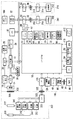
図1は、本発明の好適な実施の形態に係る電子カメラの概略構成を示す図である。
【0035】
この実施の形態に係る電子カメラは、電子カメラ本体100と、レンズユニット300とを備え、記録媒体200及び/又は210を電子カメラ本体100に装着することができる。
【0036】
先ず、電子カメラ本体100に関して説明する。図1において、14は光学像を電気信号に変換する撮像素子(例えば、CCD素子)、16は撮像素子14のアナログ信号出力をディジタル信号に変換するA/D変換器である。18は、撮像素子14、A/D変換器16、D/A変換器26にクロック信号や制御信号を供給するタイミング発生回路であり、メモリ制御回路22及びシステム制御回路50により制御される。
【0037】
20は、画像処理回路であり、A/D変換器16から出力されるデータ或いはメモリ制御回路22から出力されるデータに対して、例えば、画素補間処理や色変換処理等の画像処理を施す。
【0038】
また、画像処理回路20では、撮像に係る画像データを用いて、システム制御回路50が露光制御部340及び焦点制御部342を制御してTTL(スルー・ザ・レンズ)方式のAF(オートフォーカス)処理、AE(自動露出)処理及びEF(フラッシュプリ発光)処理を実現するための演算処理を行う。さらに、画像処理回路20では、撮像した画像データを用いて、TTL方式のAWB(オートホワイトバランス)処理を行う。
【0039】
22は、メモリ制御回路であり、A/D変換器16、タイミング発生回路18、画像処理回路20、画像表示メモリ24、D/A変換器26、メモリ30及び圧縮・伸長回路32を制御する。
【0040】
A/D変換器16から出力されるデータは、画像処理回路20及びメモリ制御回路22を介して、或いは画像処理回路20を介することなくメモリ制御回路22のみを介して、画像表示メモリ24或いはメモリ30に書き込まれる。
【0041】
24は画像表示メモリ、26はD/A変換器である。28は、例えばTFT-LCD等で構成される画像表示部である。画像表示メモリ24に書き込まれた表示用の画像データはD/A変換器26を介して画像表示部28に供給され、これにより画像が表示される。画像表示部28を用いて撮像に係る画像を逐次表示することにより、電子ファインダー機能を実現することができる。また、画像表示部28は、システム制御回路50からの指示に従って画像の表示をON/OFFする機能を有し、画像表示をOFF状態にすることにより、電子カメラ本体100の電力消費を大幅に低減することができる。
【0042】
30は、撮影した静止画像や動画像を格納するためのメモリであり、所定枚数の静止画像や所定時間の動画像を格納するために十分な記憶量を備えている。従って、複数枚の静止画像を連続して撮影する連写撮影やパノラマ撮影を行うこともできる。また、メモリ30はシステム制御回路50の作業領域としても使用され得る。
【0043】
32は、例えば適応離散コサイン変換(ADCT)等により画像データを圧縮或いは伸長する圧縮・伸長回路であり、メモリ30に格納された画像データを読み込んで圧縮処理或いは伸長処理を行い、処理済みのデータをメモリ30に書き込む。
【0044】
48はフラッシュであり、AF補助光の投光機能やフラッシュ調光機能も有する。露光制御部340及び焦点制御部342は、TTL方式により制御される。即ち、露光制御部340及び焦点制御部342は、撮像に係る画像データを画像処理回路20によって演算した演算結果に基づいてシステム制御回路50により制御される。
【0045】
50は電子カメラ本体100の全体を制御するシステム制御回路である。52はシステム制御回路50が動作する際に参照する定数、変数、プログラム等を記憶するメモリである。
【0046】
54は、システム制御回路50がプログラムに基づいて動作する際に、その実行に応じて、文字、表示、音声等により動作状態やメッセージ等を発する情報出力部であり、例えばLCDやLEDの表示素子及びスピーカ等の発音素子で構成される。情報出力部54を構成する単数或いは複数の構成要素は、例えば、電子カメラ本体100の操作部70近辺の視認し易い位置に設置される。また、情報出力部54の構成要素は、光学ファインダー104内にも配置される。
【0047】
情報出力部54による表示内容のうちLCD等により表示するものとしては、例えば、シングルショット/連写撮影表示、セルフタイマー表示、圧縮率表示、記録画素数表示、記録枚数表示、残撮影可能枚数表示、シャッタースピード表示、絞り値表示、露出補正表示、フラッシュ表示、赤目緩和表示、マクロ撮影表示、ブザー設定表示、時計用電池残量表示、電池残量表示、エラー表示、複数桁の数字による情報表示、記録媒体200及び210の着脱状態表示、レンズユニット300の着脱状態表示、通信I/F動作表示、日付け・時刻表示、外部コンピュータとの接続状態を示す表示等がある。
【0048】
また、情報出力部54による表示内容のうち光学ファインダー104内に表示するものとしては、例えば、合焦表示、撮影準備完了表示、手振れ警告表示、フラッシュ充電表示、フラッシュ充電完了表示、シャッタースピード表示、絞り値表示、露出補正表示、記録媒体書き込み動作表示等がある。
【0049】
また、情報出力部54の表示内容のうちLED等に表示するものとしては、例えば、合焦表示、撮影準備完了表示、手振れ警告表示、フラッシュ充電表示、フラッシュ充電完了表示、記録媒体書き込み動作表示、マクロ撮影設定通知表示、二次電池充電状態表示等がある。
【0050】
また、情報出力部54による表示内容のうちランプ等に表示するものとしては、例えば、セルフタイマー通知ランプ等がある。このセルフタイマー通知ランプは、AF補助光と共用であってもよい。
【0051】
56は電気的に消去・記録可能な不揮発性メモリであり、例えばEEPROM等で構成される。
【0052】
60,62,64,66,68,70及び72は、システム制御回路50に対する各種の動作指示を入力するための操作手段であり、例えば、スイッチ、ダイアル、タッチパネル、視線検知によるポインティング、音声認識装置等の単数或いは複数の組み合わせで構成される。以下に、これらの操作手段に関して具体的に説明する。
【0053】
60はモードダイアルスイッチであり、これにより操作者は、電源オフ、自動撮影モード、撮影モード、パノラマ撮影モード、再生モード、マルチ画面再生・消去モード、PC接続モード等の各機能モードを切り替えることができる。
【0054】
62はシャッタースイッチであり、シャッターボタン64の操作途中(半押し)でスイッチ信号SW1をON状態にし、AF(オートフォーカス)処理、AE(自動露出)処理、AWB(オートホワイトバランス)処理、EF(フラッシュプリ発光)処理等の動作の開始を指示する。また、シャッタースイッチ62は、シャッターボタン64の操作完了(全押し、即ち撮影指示)でスイッチ信号SW2をON状態しに、撮像素子14から出力される信号をA/D変換器16によりデジタル信号に変換し、これをメモリ制御回路22を介してメモリ30に格納する露光処理、画像処理回路20やメモリ制御回路22における演算処理による現像処理、メモリ30から画像データを読み出して、これを圧縮・伸長回路32で圧縮して記録媒体200或いは210に画像データを書き込む記録処理という一連の処理の開始を指示する。
【0055】
66は画像表示のON/OFFスイッチであり、これにより操作者は、画像表示部28への画像の表示のON/OFFを設定することができる。この機能により、TFT-LCD等で構成される画像表示部28への電流供給を任意に遮断し、省電力化を図ることができる、
68はクイックレビューのON/OFFスイッチであり、これにより操作者は、撮影直後の画像を自動再生するクイックレビュー機能を設定することができる。また、このクイックレビューのON/OFFの設定は、画像表示部28への画像の表示をOFFに設定した場合においても有効である。
【0056】
70は各種ボタンやタッチパネル等からなる操作部であり、メニューボタン、セットボタン、マクロボタン、マルチ画像再生改ページボタン、フラッシュ設定ボタン、単写/連写/セルフタイマー切り替えボタン、メニュー移動+(プラス)ボタン、メニュー移動−(マイナス)ボタン、再生画像移動+(プラス)ボタン、再生画像−(マイナス)ボタン、撮影画質選択ボタン、露光補正ボタン、日付/時間設定ボタン、パノラマモード等の撮影及び再生を実行する際に各種機能の選択及び切り替えを設定するための選択/切り替えボタン、パノラマモード等の撮影及び再生を実行する際に各種機能の決定及び実行を設定する決定/実行ボタン等がある。
【0057】
72は圧縮モードスイッチであり、JPEG圧縮の圧縮率(JPEG圧縮のモード)を選択するため、或いは、撮像素子14から出力される信号をそのままデジタル化して記録媒体に記録するCCDRAWモードを選択するためのスイッチである。
【0058】
JPEG圧縮のモードとしては、例えばノーマルモードとファインモードが用意されている。JPEG圧縮のモードでは、撮像素子14から読み出されてA/D変換器16、画像処理回路20及びメモリ制御回路22を介してメモリ30に書き込まれた画像データをメモリ30から読み出し、圧縮・伸長回路32により設定された圧縮率で圧縮を行った後に、その圧縮済みの画像データを記録媒体200或いは210に記録する。
【0059】
CCDRAWモードでは、撮像素子14の色フィルタの画素配列に応じてライン毎にそのまま撮像素子14から読み出して、A/D変換器16及びメモリ制御回路22を介してメモリ30に書き込まれた画像データをメモリ30から読み出し、記録媒体200或いは210に記録する。
【0060】
80は電源制御部であり、例えば、電池検出回路、DC−DCコンバータ、通電するブロックを切り替えるスイッチ回路等により構成されており、電池の装着の有無、電池の種類及び電池残量を検出し、その検出結果及びシステム制御回路50の指示に基づいてDC−DCコンバータを制御して、必要な電圧を必要な期間だけ各部(記録媒体、レンズユニットを含む)に供給する。82,84はコネクタ、86は、例えば、アルカリ電池やリチウム電池等の一次電池、NiCd電池、NiMH電池、Li電池等の二次電池、ACアダプタ等で構成される電源部である。
【0061】
90及び94はメモリカードやハードディスク等の記録媒体200及び210と接続するためのインターフェース、92及び96は記録媒体200及び210を保持するためのコネクタ、98はコネクタ92或いは96に記録媒体200或いは210が装着されているか否かを検知する記録媒体着脱検知部である。
【0062】
なお、この実施の形態は、記録媒体を装着するためのインターフェース及びコネクタを2系統持つものとして説明しているが、記録媒体を装着(保持)するためのインターフェース及びコネクタの系統は、単数でもよいし複数でもよい。インターフェース及びコネクタとしては、PCMCIAカードやCF(コンパクトフラッシュ)カード等の規格に準拠したものを用いて構成しても構わない。
【0063】
さらに、インターフェース90及び94並びにコネクタ92及び96をPCMCIAカードやCF(コンパクトフラッシュ)カード等の規格に準拠したものを用いて構成した場合、LANカード、モデムカード、USBカード、IEEE1394カード、P1284カード、SCSIカード、PHS等の通信カード等の各種通信カードを接続することにより、他のコンピュータやプリンタ等の周辺機器との間で画像データや画像データに付属した管理情報を相互に転送することができる。
【0064】
104は光学ファインダーであり、この光学ファインダー104を利用することにより、画像表示部28を利用した電子ファインダー機能を使用することなく、撮影を行うことができる。また、光学ファインダー104内には、情報出力部54の一部の構成要素、例えば、合焦表示、手振れ警告表示、フラッシュ充電表示、シャッタースピード表示、絞り値表示、露出補正表示等のための素子が設置されている。
【0065】
110は通信部であり、例えば、RS232C、USB、IEEE1394、P1284、SCSI、モデム、LAN、無線通信等による通信を行う。112は、通信部110と協同して電子カメラ本体100を他の機器と接続するためのコネクタ或いは無線通信用のアンテナである。
【0066】
120は、レンズマウント106内において、電子カメラ本体100をレンズユニット300と接続するためのインターフェース、122は電子カメラ本体100をレンズユニット300と電気的に接続するためのコネクタ、124はレンズマウント106及び/或いはコネクタ122にレンズユニット300が装着されているか否かを検知するレンズ着脱検知部である。
【0067】
コネクタ122は、電子カメラ本体100とレンズユニット300との間で制御信号、状態信号、データ信号等を相互に伝達する機能及び各種電圧の電流をレンズユニット300に供給する機能を備えている。なお、コネクタ122は、電気信号のみならず、光信号、音声信号等を伝達する構成としても良い。
【0068】
200はメモリカードやハードディスク等を含む記録媒体である。記録媒体200は、半導体メモリや磁気ディスク等で構成される記録部202、電子カメラ本体100と接続するためのインターフェース204及びコネクタ206を備えている。
【0069】
210はメモリカードやハードディスク等を含む記録媒体である。記録媒体210は半導体メモリや磁気ディスク等で構成される記録部212、電子カメラ本体100と接続するためのインターフェース214及びコネクタ216を備えている。
【0070】
300は交換レンズタイプのレンズユニットである。306は、レンズユニット300を電子カメラ本体100と機械的に結合するためのレンズマウントである。レンズマウント306内には、レンズユニット300を電子カメラ100と電気的に接続するための各種機能が含まれている。
【0071】
310は撮影レンズ、312は絞り機能を備えるシャッターである。320は、レンズマウント306内において、レンズユニット300を電子カメラ本体100と接続するためのインターフェース、322はレンズユニット300を電子カメラ本体100と電気的に接続するためのコネクタである。
【0072】
コネクタ322は、電子カメラ本体100とレンズユニット300との間で制御信号、状態信号、データ信号等を相互に伝達するための機能及び各種電圧の電流を入力する機能を備えている。また、コネクタ322は、電気信号のみならず、光信号、音声信号等を伝達する構成としても良い。
【0073】
340は、絞り機能を備えるシャッター312を制御する露光制御部であり、フラッシュ48と連携することによりフラッシュ調光機能を実現している。342は撮影レンズ10のフォーカシングを制御する焦点制御部、344は撮影レンズ10のズーミングを制御するズーム制御部である。
【0074】
350はレンズユニット300の全体を制御するレンズシステム制御回路である。レンズシステム制御回路350は、動作用の定数、変数、プログラム等を記憶するメモリや、レンズユニット300の識別情報(例えば固有の番号)、管理情報、開放絞り値、最小絞り値、焦点距離等の機能情報、現在や過去の各設定値などを保持する不揮発性メモリの機能を備えている。
【0075】
以下、図2乃至図8を参照して、第1の実施の形態に係る電子カメラの動作を説明する。
【0076】
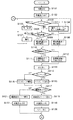
図2乃至図4は、電子カメラ本体100を制御する主ルーチンのフローチャートである。電池交換等がなされて電源が投入されると、ステップS101において、システム制御回路50は、フラグや制御変数等を初期化し、次いで、ステップS102において、画像表示部28の画像表示をOFF状態に設定する。
【0077】
ステップS103では、システム制御回路50は、モードダイアル60の設定位置を確認し、モードダイアル60が電源OFFの位置に設定されている場合は、各表示部の表示を終了状態に変更し、フラグや制御変数等を含む必要なパラメータや設定値及び設定モードを不揮発性メモリ56に記憶し、電源制御部80に命じて、画像表示部28を含めて電子カメラ本体100の各部の不要な電源を遮断するための所定の終了処理を行った後にステップS103に戻る。
【0078】
また、ステップS103において、モードダイアル60が撮影モードの位置に設定されている場合はステップS106に進む。また、ステップS103において、モードダイアル60がその他のモードの位置に設定されている場合は、ステップS104において、システム制御回路50は選択されたモードに応じた処理を実行した後にステップS103に戻る。
【0079】
ステップS106では、システム制御回路50は、電源制御部80により電池等により構成される電源部86の残容量や動作状況が電子カメラ本体100の動作に支障があるか否かを判断する。そして、動作に支障があると判断した場合は、システム制御回路50は、ステップS107において、情報出力部54を用いて表示や音声により所定の警告を発した後にステップS103に戻る。なお、画像表示部28の画像表示がON状態である場合は、画像表示部28をも利用して警告を発してもよい。
【0080】
また、ステップS106において、電源部86の残容量が所定の閾値より多いと判断した場合は、ステップS109において、システム制御回路50は、電池残容量を示すフラグを、電子カメラ本体100の動作を継続するために十分であることを示すHに設定すると共に表示設定を「電池残容量H」に設定して、ステップS110に進む。
【0081】
また、ステップS106において、電源部86の残容量が所定の閾値より少ないと判断した場合は、電池残容量を示すフラグを、電子カメラ本体100の動作を継続する上で電源部86の残容量が残り少ない状態であることを示すLに設定すると共に表示設定を「電池残容量L」に設定して、ステップS110に進む。
【0082】
なお、電池残容量を示すフラグの状態は、例えば、システム制御回路50の内部メモリ或いはメモリ52に記憶される。
【0083】
ステップS110では、システム制御回路50は、記録媒体着脱検知部98に問合わせることにより、記録媒体200或いは210が電子カメラ100に装着されているか否かを確認し、いずれかが装着されていると判断した場合はステップS111において表示設定を「記録媒体有り」に設定し、いずれも装着されていないと判断した場合はステップS112において表示設定を「記録媒体無し」に設定する。
【0084】
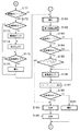
ステップS113では、システム制御回路50は、情報出力部54を利用して、表示設定の内容に基づいて、表示や音声により電池残容量や記録媒体の装着に関する情報を含む電子カメラ本体100の各種設定状態の表示を行う。なお、画像表示部28の画像表示がON状態である場合は、画像表示部28をも利用して電子カメラ本体100の各種設定状態の表示を行ってもよい。
【0085】
ステップS114では、システム制御回路50は、クイックレビューのON/OFFスイッチ68の設定状態を確認し、クリックレビューがON状態に設定されていると判断した場合は、ステップS115において、クイックレビューフラグを設定し、一方、クイックレビューがOFF状態に設定されてると判断した場合は、ステップS116において、クイックレビューフラグを解除する。
【0086】
なお、クイックれビューフラグの状態は、例えば、システム制御回路50の内部メモリ或いはメモリ52に記憶される。
【0087】
ステップS117では、システム制御回路50は、画像表示部28への画像の表示を設定するON/OFFスイッチ66の設定状態を確認し、ON状態に設定されていると判断した場合は、ステップS118において画像表示フラグを設定し、ステップS119において画像表示部28の画像表示をON状態に設定し、ステップS120において、撮像した画像を逐次表示するスルー表示状態に設定して、ステップS131に進む。
【0088】
スルー表示状態においては、撮像素子14、A/D変換器16、画像処理回路20及びメモリ制御回路22を介して画像表示メモリ24に逐次書き込まれた画像データを、メモリ制御回路22及びD/A変換器26を介して画像表示部28に逐次転送して画像表示部28に画像を表示することにより、画像表示部28を電子ファインダーとして機能させる。
【0089】
ステップS117において、画像表示に関するON/OFFスイッチ66がOFF状態に設定されていると判断した場合は、ステップS121において、画像表示フラグを解除し、ステップS122において、画像表示部28の画像表示をOFF状態に設定して、ステップS131に進む。
【0090】
画像表示部28への画像表示がOFF状態である場合は、操作者は、画像表示部28による電子ファインダー機能ではなく、光学ファインダー104を利用して撮影を行う。この場合、電力消費量の大きい画像表示部28やD/A変換器266等における電力消費を削減することができる。
【0091】
なお、画像表示フラグの状態は、例えば、システム制御回路50の内部メモリ或いはメモリ52に記憶される。
【0092】
ステップS131では、スイッチ信号SW1がON状態(シャッターボタン64が半押しの状態)であるか否かを確認し、OFF状態であればステップS103に戻る。
【0093】
一方、スイッチ信号SW1がON状態であれば、システム制御回路50は、ステップS132において、システム制御回路50の内部メモリ或いはメモリ52に記憶されている画素表示フラグの状態を確認し、画像表示フラグが設定されている場合はステップS135に進み、画像表示フラグが解除されている場合はステップS133に進む。
【0094】
ステップS133では、システム制御回路50は、記録媒体着脱検知部98に問合わせることにより、記録媒体200或いは210が電子カメラ本体100に装着されているか否かを確認し、いずれかが装着されていると判断した場合はステップS136に進む。
【0095】
一方、記録媒体200或いは210のいずれも電子カメラ本体100に装着されていないと判断した場合は、システム制御回路50は、ステップS134において画像表示部28の画像表示をON状態に設定し、ステップS135に進む。
【0096】
ステップS135では、システム制御回路50は、画像表示部28の表示状態をフリーズ表示状態に設定してステップS136に進む。フリーズ表示状態では、撮像素子14、A/D変換器16、画像処理回路20及びメモリ制御回路22を介して画像表示メモリ24内の画像データを書き換えることを禁止し、直前に画像表示メモリ24に書き込まれた画像データをメモリ制御回路22及びD/A変換器26を介して画像表示部28に転送することにより、電子ファインダーとしての画像表示部28にフリーズした映像を表示する。
【0097】
ステップS136では、システム制御回路50は、記録媒体着脱検知部98に問合わせることにより、記録媒体200或いは210が電子カメラ本体100に装着されているか否かを確認し、いずれかが装着されていると判断した場合は、ステップS138に進む。
【0098】
一方、記録媒体200或いは210のいずれも電子カメラ本体100に装着されていないと判断した場合は、ステップS137において、システム制御回路50は、情報出力部54或いは画像表示部28を利用して表示や音声により記録媒体200或いは210のいずれも電子カメラ本体100に装着されていないことを操作者に対して警告し、ステップS138に進む。
【0099】
このように、スイッチ信号SW1がON状態になった時、即ち、シャッターボタン64が半押し状態にされた時に、記録媒体200或いは210が電子カメラ本体100に装着されているか否かを確認し、いずれも装着されていない場合にはその旨の警告を行うことにより、操作者が記録媒体に画像を記録することができない事に気付かず誤って撮影動作を続行することを防止することができる。また、シャッターボタン64が半押しの状態にされた時に記録媒体200或いは210のいずれも電子カメラ本体100に装着されていない場合、画像表示部28の画像表示がOFF状態に設定されていても、これをON状態に切り換えて警告を表示することにより、操作者が記録媒体に画像を記録することができない事に気付かず誤って撮影動作を続行することを防止することができる。一般的に、TFT-LCD等で構成される画像表示部28は情報出力部54の表示素子よりも大型であるため、画像表示部28を利用して操作者に警告を発することにより、操作者への警告を効果的に行うことができる。
【0100】
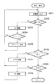
ステップS138では、システム制御回路50は、焦点制御部342等を制御して撮影レンズ310の焦点を撮像素子14の撮像面に合わせると共に露光制御部340等を制御して測光処理を行って絞り値及びシャッター時間を決定する。なお、測光処理においては、必要であればフラッシュの設定も行う。この測距・測光処理(ステップS138)の詳細は図5を参照して後述する。
【0101】
ステップS139では、システム制御回路50は、システム制御回路50の内部メモリ或いはメモリ52に記録されている画像表示フラグの状態を確認し、画像表示フラグが設定されている場合はステップS142に進む。
【0102】
一方、画像表示フラグが解除されている場合は、ステップS140において、システム制御回路50は、記録媒体着脱検知部98に問合わせることにより、記録媒体200或いは210が電子カメラ本体100に装着されているか否かを確認し、いずれかが装着されていると判断した場合はステップS143に進む。
【0103】
一方、記録媒体200或いは210のいずれも電子カメラ本体100に装着されていないと判断した場合は、ステップS141において、システム制御回路50は、画像表示部28の画像表示をON状態に設定し、ステップS142に進む。
【0104】
ステップS142では、システム制御回路50は、画像表示部28の表示状態をスルー表示状態に設定してS143に進む。なお、ステップS142におけるスルー表示状態は、ステップS120におけるスルー表示状態と同じ動作状態である。
【0105】
ステップS143では、システム制御回路50は、記録媒体着脱検知部98に問合わせることにより、記録媒体200或いは210が電子カメラ本体100に装着されているか否かを確認し、いずれかが装着されていると判断した場合はステップS145に進む。
【0106】
一方、記録媒体200或いは210のいずれも電子カメラ本体100に装着されていないと判断した場合は、ステップS144において、情報出力部54及び/或いは画像表示部28を利用して表示や音声により、記録媒体200或いは210のいずれも画像処理装置100に装着されていないことを警告し、ステップS145に進む。
【0107】
このように、スイッチ信号SW1がON状態(シャッターボタン64が半押しの状態)になり、測距・測光処理が行われた後に、記録媒体200或いは210が電子カメラ本体100に装着されているか否かを確認し、いずれも装着されていない場合にはその旨の警告を行うことにより、操作者が記録媒体に画像を記録することができない事に気付かず誤って撮影動作を続行することを防止することができる。また、シャッターボタン64が半押しの状態にされ、測距・測光処理が行われた後に、記録媒体200或いは210のいずれも電子カメラ本体100に装着されていない場合、画像表示部28の画像表示がOFF状態に設定されていても、これをON状態に切り換えて警告を表示することにより、操作者が記録媒体に画像を記録することができない事に気付かず誤って撮影動作を続行することを防止することができる。一般的に、TFT-LCD等で構成される画像表示部28は情報出力部54の表示素子よりも大型であるため、画像表示部28を利用して警告を発することにより、操作者への警告を効果的に行うことができる。
【0108】
ステップS145では、スイッチ信号SW2がON状態、即ち、撮影指示状態であるか否かを確認し、スイッチ信号SW2がOFF状態であればステップS160に進む。そして、ステップS160において、スイッチ信号SW1がON状態であるか否かを確認し、OFF状態であればステップS103に戻り、ON状態であればステップS145に戻る。
【0109】
一方、スイッチ信号SW2がON状態、即ち、撮影が指示されたと判断した場合は、ステップS171において、システム制御回路50は、システム制御回路50の内部メモリ或いはメモリ52に記憶されている画像表示フラグの状態を確認し、画像表示フラグが設定されている場合はステップS173に進む。
【0110】
一方、画像表示フラグが解除されている場合は、ステップS172において、システム制御回路50は、記録媒体着脱検知部98に問合わせることにより、記録媒体200或いは210が電子カメラ本体100に装着されているか否かを確認し、いずれかが装着されていると判断した場合はステップS175に進む。
【0111】
一方、記録媒体200或いは210のいずれも電子カメラ本体100に装着されていないと判断した場合は、システム制御回路40は、ステップS172において、画像表示部28への画像表示をON状態に設定し、ステップS174に進む。
【0112】
ステップS174では、システム制御回路50は、画像表示部28の表示状態を固定色表示状態に設定してステップS175に進む。固定色表示状態では、撮像素子14、A/D変換器16、画像処理回路20及びメモリ制御回路22を介して画像表示メモリ24に書き込まれた画像データの代わりに、固定色の画像データをメモリ制御回路22及びD/A変換器26を介して画像表示部28に供給し、電子ファインダーとしての画像表示部28に固定色の映像(警告画像)を表示する。
【0113】
ステップS175では、システム制御回路50は、記録媒体着脱検知部98に問合わせることにより、記録媒体200或いは210が電子カメラ本体100に装着されているか否かを確認し、いずれかが装着されていると判断した場合はステップS181に進む。
【0114】
一方、記録媒体200或いは210のいずれも電子カメラ本体100に装着されていないと判断した場合は、ステップS176において、システム制御回路50は、情報出力部54及び/或いは画像表示部28を利用して表示や音声により記録媒体200或いは210のいずれも電子カメラ本体100に装着されていないことを操作者に警告し、ステップS181に進む。
【0115】
このように、スイッチ信号SW2がON状態、即ち、撮影が指示された際に、記録媒体200或いは210が電子カメラ本体100に装着されているか否かを確認し、いずれも装着されていない場合はその旨を操作者に警告することにより、操作者が記録媒体に画像を記録することができない事に気付かず誤って撮影動作を続行することを防止することができる。また、撮影が指示された際に、記録媒体200或いは210のいずれも電子カメラ本体100に装着されていない場合、画像表示部28の画像表示がOFF状態に設定されている場合であっても、これをON状態に切り換えて警告表示を行うことにより、操作者が記録媒体に画像を記録することができない事に気付かず誤って撮影動作を続行することを防止することができる。一般的に、TFT-LCD等で構成される画像表示部28は情報出力部54よりも大型であるため、画像表示部28を利用して操作者に警告を発することにより、操作者への警告を効果的に行うことができる。
【0116】
ステップS181では、システム制御回路50は、撮像素子14、A/D変換器16、画像処理回路20及びメモリ制御回路22を介して、或いは、画像処理回路20を介さずにA/D変換器16及びメモリ制御回路22を介して、メモリ30に撮影に係る画像データを書き込む露光処理、及び、メモリ制御回路22の他必要に応じて画像処理回路20を用いて、メモリ30に書き込まれた画像データを読み出して各種処理を行う現像処理からなる撮影処理を実行する。この撮影処理(ステップS181)の詳細は図6を参照して後述する。
【0117】
ステップS182では、システム制御回路50は、撮影処理(ステップS181)によってメモリ30に書き込まれた画像データを読み出して、メモリ制御回路22を介して画像表示メモリ24に転送する表示画像処理を実行する。この表示画像処理(ステップS182)の詳細は図7を参照して後述する。
【0118】
ステップS183では、システム制御回路50は、システム制御回路50の内部メモリ或いはメモリ52に記憶されている画像表示フラグの状態を確認し、画像表示フラグが設定されている場合はステップS187に進む。この場合は、撮影中も画像表示部28が常に電子ファインダーとして利用され、撮影直後のクイックレビュー表示も行われる。
【0119】
一方、画像表示フラグが解除されている場合は、ステップS184において、システム制御回路50は、記録媒体着脱検知部98に問合わせることにより、記録媒体200或いは210が電子カメラ本体100に装着されているか否かを確認し、いずれかが装着されていると判断した場合はステップS185に進み、いずれも装着されていないと判断した場合はステップS186に進む。
【0120】
ステップS185では、システム制御回路50は、システム制御回路50の内部メモリ或いはメモリ52に記憶されているクイックレビューフラグの状態を確認し、クイックレビューフラグが設定されていない場合は、画像表示部28をOFFの状態に維持したままステップS189に進む。この場合は、撮影後においても画像表示部28はOFF状態であり、クイックレビュー表示も行われない。これは、例えば、光学ファインダー104を利用して撮影を連続的に行う場合のように、撮影直後の撮影画像の確認が不要である場合に好適な使用方法であり、省電力を重視する使用方法でもある。
【0121】
一方、クイックレビューフラグが設定されている場合は、システム制御回路50は、ステップS186において画像表示部28の画像表示をON状態に設定し、ステップS187において、画像表示部28を利用してクイックレビュー表示を行う。このように、画像表示部28の画像表示をOFF状態に設定した場合においても、クイックレビューのON/OFFスイッチ72によりクイックレビュー機能が設定されている場合は、撮影直後に自動的に撮影画像が画像表示部28に再生される。これは、省電力と撮影画像の確認との両立を図る使用方法である。
【0122】
ステップS188では、システム制御回路50は、記録媒体着脱検知部98に問合わせることにより、記録媒体200或いは210が電子カメラ本体100に装着されているか否かを確認し、いずれかが装着されていると判断した場合はステップS189に進む。
【0123】
一方、記録媒体200或いは210のいずれも電子カメラ本体100に装着されていないと判断した場合は、情報出力部54及び/或いは画像表示部28を利用して表示や音声により記録媒体200或いは210のいずれも電子カメラ本体100に装着されていないことを操作者に警告し、ステップS151に進む。
【0124】
このように、スイッチ信号SW2がON状態にされ、撮影処理(ステップS181)、表示画像処理(ステップS182)が行われた後に、記録媒体200或いは210が電子カメラ本体100に装着されているか否かを確認し、いずれも装着されていない場合はその旨を操作者に警告することにより、操作者が記録媒体に画像を記録することができない事に気付かず誤って撮影動作を続行することを防止することができる。また、スイッチ信号SW2がON状態にされ、撮影処理(ステップS181)、表示画像処理(ステップS182)が行われた後に、記録媒体200或いは210が電子カメラ本体100に装着されているか否かを確認し、いずれも装着されていない場合、画像表示部28の画像表示がOFF状態に設定されている場合であっても、これをON状態に切り換えて警告表示を行うことにより、操作者が記録媒体に画像を記録することができない事に気付かず誤って撮影動作を続けることを防止することができる。一般的に、TFT-LCD等で構成される画像表示部28は情報出力部54よりも大型であるため、画像表示部28を利用して操作者に警告を発することにより、操作者への警告を効果的に行うことができる。
【0125】
ステップS189では、システム制御回路50は、メモリ30に書き込まれた撮影画像データを読み出して、メモリ制御回路22の他必要に応じて画像処理回路20を用いて各種画像処理を行い、また、圧縮・伸長回路32を用いて、設定したモードに応じて画像圧縮処理を行う。この圧縮処理(ステップS189)の詳細は図8を参照して後述する。
【0126】
ステップS190では、システム制御回路50は、インターフェース90或いは94及びコネクタ92或いは96を介して、メモリカードやコンパクトフラッシュカード等の記録媒体200或いは210に画像データを記録し、ステップS151に進む。なお、画像表示部28がON状態の場合は、記録媒体200或いは210に対して画像データを書き込んでいる間、書き込み動作中であることを示す情報、例えば「BUSY」のような文字列を画像表示部28に表示してもよい。また、情報出力部54においても、例えばLEDを点滅させることにより、記録媒体に対する画像データの書き込み動作中であることを表示してもよい。
【0127】
このように、記録媒体200或いは210が電子カメラ本体100に装着されている場合は、圧縮処理(ステップS189)及び記録処理(ステップS190)を順次実行して、記録媒体200或いは210に撮影に係る画像データを順次記録することができる。
【0128】
ステップS151では、システム制御回路50は、スイッチ信号SW2がON状態、即ち、撮影の指示が継続しているか否かを確認し、スイッチ信号SW2がON状態であれば、ステップS152において、システム制御回路50は、システム制御回路50の内部メモリ或いはメモリ52に記憶されている連写フラグの状態を確認し、連写フラグが設定されている場合は、ステップS181に戻り、次の撮影を行う。
【0129】
一方、連写フラグが設定されていない場合は、スイッチ信号SW2がOFF状態に復帰するまで、即ち、撮影指示が解除されるまで、ステップS151及びS152の処理を繰り返す。
【0130】
このように、この実施の形態では、撮影直後にクイックレビュー表示を行うように設定されている場合において、記録処理(ステップS190)或いは警告処理(ステップS191)が終了した際にスイッチ信号SW2がON状態(撮影指示状態)であれば、スイッチ信号SW2がOFF状態に復帰するまで画像表示部28におけるクイックレビュー表示を継続するため、操作者は、撮影画像の確認を入念に行うことができる。
【0131】
一方、ステップS151において、スイッチ信号SW2がOFF状態であると判断した場合は、ステップS153において、所定のミニマムレビュー時間が経過するのを待った後にステップS154に進む。なお、このミニマムレビュー時間は、固定値としてもよいし、操作者が任意に設定することができるように構成してもよい。
【0132】
このように、この実施の形態では、画像表示部28におけるクイックレビュー表示を所定の時間継続することにより、操作者が撮影画像の確認を確実に行うことを可能とすると共に、長時間にわたって不必要にクイックレビュー表示を継続することによって次の撮影チャンスが失われることを防止する。
【0133】
ステップS154では、システム制御回路50は、画像表示フラグの状態を確認し、画像表示フラグが設定されている場合はステップS157に進み、設定されていない場合はステップS156に進む。
【0134】
ステップS157では、システム制御回路50は、画像表示フラグの状態に拘らず、画像表示部28の表示状態をスルー表示状態に設定して、ステップS158に進む。これにより、画像表示部28におけるクイックレビュー表示によって撮影画像を操作者が確認した後に、画像表示部28は、次の撮影のためにスルー表示状態になる。
【0135】
ステップS155では、ステム制御回路50は、記録媒体着脱検知部98に問合わせることにより、記録媒体200或いは210が電子カメラ本体100に装着されているか否かを確認し、いずれかが装着されている場合は、ステップS156において、画像表示部28の画像表示をOFF状態に設定して、ステップS158に進む。この場合、画像表示部28におけるクイックレビュー表示によって操作者が撮影画像を確認した後に画像表示部28がOFF状態にされるため、電力消費量の大きい画像表示部28やD/A変換器26等による電力消費が削減される。
【0136】
一方、記録媒体200或いは210のいずれも電子カメラ本体100に装着されていない場合は、ステップS157において、システム制御回路50は、画像表示フラグの状態に拘らず、画像表示部28の画像表示をスルー表示状態に設定する。
【0137】
ステップS158では、システム制御回路50は、記録媒体着脱検知部98に問合わせることにより、記録媒体200或いは210が電子カメラ本体100に装着されているか否かを確認し、いずれかが装着されていると判断した場合はステップS160に進む。
【0138】
一方、記録媒体200或いは210のいずれも電子カメラ本体100に装着されていないと判断した場合は、ステップS159において、システム制御回路50は、情報出力部54及び/或いは画像表示部28を利用して表示や音声により記録媒体200或いは210のいずれも電子カメラ本体100に装着されていないことを警告し、ステップS160に進む。
【0139】
このように、スイッチ信号SW2がOFF状態にされた際に、記録媒体200或いは210が電子カメラ本体100に装着されいるか否かを確認し、いずれも装着されていない場合はその旨の警告を行うことにより、操作者が記録媒体に画像を記録することができいない事に気付かず誤って撮影動作を続行することを防止することができる。また、スイッチ信号SW2がOFF状態にされた際に、記録媒体200或いは210のいずれも電子カメラ本体100に装着されていない場合、画像表示フラグが解除されている場合においても、画像表示部28の画像表示をOFF状態に設定することなくスルー表示状態に設定して警告を表示することにより、操作者が記録媒体に画像を記録することができいない事に気付かず誤って撮影動作を続行することを防止することができる。一般的に、TFT-LCD等で構成される画像表示部28は情報出力部54よりも大型であるため、画像表示部28を利用して操作者に警告を発することにより、操作者への警告を効果的に行うことができる。
【0140】
ステップS160では、スイッチ信号SW1がON状態であるか否かを確認し、ON状態であればステップS145に進んで次の撮影に備え、OFF状態であれば一連の撮影動作を終えてステップS103に戻る。
【0141】
以上説明したように、この実施の形態によれば、記録媒体が装着されていない状態で撮影に関する動作を実行した場合に、情報出力部54及び/或いは画像表示部28を利用して所定の警告を行うことにより、記録媒体が未装着のままで失敗撮影がなさることを防止することができる。
【0142】
また、この実施の形態によれば、画像表示部28がOFF状態であっても、記録媒体が未装着のまま撮影動作を実行した場合に、画像表示部28をON状態に切り換えて画像表示部28を利用して所定の警告を行うことにより、記録媒体が未装着のままで失敗撮影がなされることを防止することができる。
【0143】
さらに、この実施の形態によれば、シャッターボタン64が押されて撮影動作に入った際に記録媒体が未装着の状態である場合に、画像表示部28がOFF状態であっても、これをON状態に切り換えた後に、画像表示部28により、スルー画像、フリーズ画像、固定色画像、クイックレビュー画像等の各画像表示を行うと共に所定の警告を行うことにより、記録媒体が未装着のままで失敗撮影がなされることを防止することができる。
【0144】
図5は、測距・測光処理(図3のステップS138)の詳細を示すフローチャートである。ステップS201において、システム制御回路50は、撮像素子14から出力される電荷信号をA/D変換器16によりデジタル画像データに変換して画像処理回路20に逐次読み込む。
【0145】
この逐次読み込まれた画像データを利用して、画像処理回路20は、TTL(スルー・ザ・レンズ)方式のAE(自動露出)処理、EF(フラッシュプリ発光)処理及びAF(オートフォーカス)処理のための所定の演算を行う。なお、ここ演算処理は、撮影に係る全画素のうち必要な部分を抽出した画素を対象としてなされる。これにより、TTL方式のAE、EF、AWB及びAFの各処理において、例えば、中央重点モード、平均モード、評価モード等の各モード毎に最適な演算を行うことができる。
【0146】
ステップS202では、システム制御回路50は、画像処理回路20による演算結果に基づいて露出(AE)が適正であるか否かを判断し、露出(AE)が適正でないと判断した場合にはステップS203に進み、露光制御部340を用いてAE制御を行う。
【0147】
ステップS204では、AE制御で得られた測定データを用いて、システム制御回路50は、フラッシュが必要か否かを判断し、フラッシュが必要であれば、ステップS205においてフラッシュフラグをセットし、フラッシュ48を充電する。
【0148】
AE制御を繰り返した後、ステップS202において、露出(AE)が適正であると判断した場合は、システム制御回路50は、測定データ及び/或いは設定パラメータをシステム制御回路50の内部メモリ或いはメモリ52に記憶する。
【0149】
ステップS206では、画像処理回路20による演算結果及びAE制御で得られた測定データを用いて、システム制御回路50は、ホワイトバランス(AWB)が適正であるか否かを判断し、適正でなければステップS207において、画像処理回路20を用いて色処理のパラメータを調節してAWB制御を行う。
【0150】
AWB制御を繰り返した後、ステップS206において、ホワイトバランス(AWB)が適正であると判断した場合は、システム制御回路50は、測定データ及び/或いは設定パラメータをシステム制御回路50の内部メモリ或いはメモリ52に記憶する。
【0151】
ステップS208では、AE制御及びAWB制御で得られた測定データを用いて、システム制御回路50は、焦点が撮像面に合っているか否かを判断し、焦点が合っていなければステップS209において、焦点制御回路42を用いてAF制御を行う(S209)。
【0152】
AF制御を繰り返した後、ステップS208において、焦点が撮像面に合っていると判断した場合(合焦)は、システム制御回路50は、測定データ及び/或いは測定パラメータをシステム制御回路50の内部メモリ或いはメモリ52に記憶し、測距・測光処理ルーチン(ステップS138)を終了する。
【0153】
図6は、撮影処理(図4のステップS181)の詳細を示すフローチャートである。ステップS301において、システム制御回路50は、その内部メモリ或いはメモリ52に記憶されている測光データに従って、露光制御部340に命じて、絞り機能を有するシャッター312を絞り値に応じて開放し、ステップS302において撮像素子14の露光を開始する。
【0154】
ステップS303では、システム制御回路50は、フラッシュ・フラグの状態を参照してフラッシュ48が必要であるか否かを判断し、必要な場合はにはステップS304においてフラッシュを発光させる。
【0155】
ステップS305では、システム制御回路50は、測光データに従って撮像素子14の露光終了を待ち、その後、シャッター312を閉じさせる。
【0156】
ステップS307では、撮像素子14から電荷信号を読み出して、これをA/D変換器16、画像処理回路20及びメモリ制御回路22を介して、或いは、画像処理回路20を介さずにA/D変換器16及びメモリ制御回路22を介して、撮影に係る画像データをメモリ30に書込み、撮影処理ルーチン(ステップS181)を終了する。
【0157】
図7は、表示画像処理(図4のステップS182)の詳細を示すフローチャートである。ステップS401では、システム制御回路50は、設定された撮影モードに応じてフレーム処理を行う必要があるか否かを判断し、その必要があればステップS402に進み、必要がなければステップS404に進む。
【0158】
ステップS402では、システム制御回路50は、メモリ制御回路50の他必要に応じて画像処理回路20を用いて、メモリ30に書き込まれた画像データを読み出して垂直加算処理を実行し、ステップS403では色処理を実行し、処理後の画像データをメモリ30に書き込む。
【0159】
ステップS404では、システム制御回路50は、メモリ30から画像データを読み出し、これをメモリ制御回路22を介して画像表示メモリ24に転送し、表示画像処理ルーチン(ステップS182)を終了する。
【0160】
図8は、圧縮処理(図4のステップS189)の詳細を示すフローチャートである。ステップS501では、システム制御回路50は、メモリ制御回路22の他必要に応じて画像処理回路20を用いて、メモリ30に書き込まれた画像データを読み出して、各画素の縦横の比率(縦横画素比率)が1:1になるように画素を補間する画素正方化処理を行った後、メモリ30に処理後の画像データを書き込む。
【0161】
ステップS502では、メモリ30から画像データを読み出して、圧縮・伸長回路32を用いて、設定されたモードに応じて画像を圧縮し、圧縮処理ルーチン(ステップS189)を終了する。
【0162】
[第2の実施の形態]
この実施の形態は、第1の実施の形態に係る電子カメラにおける制御手順を変更したものである。図9乃至図11並びに図5乃至図8に、この実施の形態に係る制御手順が示されている。なお、図5乃至図8に示す処理に関しては、第1の実施の形態と同様であるため説明を省略する。
【0163】
以下、図9乃至図11を参照しながら、この実施の形態に係る電子カメラ本体100の動作を説明する。電池交換等がなされて電源が投入されると、ステップS601において、システム制御回路50は、フラグや制御変数等を初期化し、次いで、ステップS602において、画像表示部28の画像表示をOFF状態に設定する。
【0164】
ステップS603では、システム制御回路50は、モードダイアル60の設定位置を確認し、モードダイアル60が電源OFFの位置に設定されている場合は、各表示部の表示を終了状態に変更し、フラグや制御変数等を含む必要なパラメータや設定値及び設定モードを不揮発性メモリ56に記録し、電源制御部80に命じて、画像表示部28を含めて電子カメラ本体100の各部の不要な電源を遮断するための所定の終了処理を行った後にステップS603に戻る。
【0165】
また、ステップS603において、モードダイアル60が撮影モードの位置に設定されている場合はステップS606に進む。また、ステップS603において、モードダイアル60がその他のモードの位置に設定されている場合は、ステップS604において、システム制御回路50は選択されたモードに応じた処理を実行した後にステップS603に戻る。
【0166】
ステップS606では、システム制御回路50は、電源制御部80により電池等により構成される電源部86の残容量や動作状況が電子カメラ本体100の動作に支障があるか否かを否かを判断する。そして、動作に問題があると判断した場合は、システム制御回路50は、ステップS607において、情報出力部54を用いて表示や音声により所定の警告を発した後にステップS603に戻る。なお、画像表示部28の画像表示がON状態である場合は、画像表示部28をも利用して警告を発してもよい。
【0167】
また、ステップS606において、電源部86の残容量が所定の閾値より多いと判断した場合は、ステップS609において、システム制御回路50は、電池残容量を示すフラグを、電子カメラ本体100の動作を継続するために十分であることを示すHに設定すると共に表示設定を「電池残容量H」に設定して、ステップS610に進む。
【0168】
また、ステップS606において、電源部86の残容量が所定の閾値より少ないと判断した場合は、電池残容量を示すフラグを、電子カメラ本体100の動作を継続する上で電源部86の残容量が残り少ない状態であることを示すLに設定すると共に表示設定を「電池残容量L」に設定して、ステップS610に進む。
【0169】
なお、電池残容量を示すフラグの状態は、例えば、システム制御回路50の内部メモリ或いはメモリ52に記憶される。
【0170】
ステップS610では、システム制御回路50は、記録媒体着脱検知部98に問合わせることにより、記録媒体200或いは210が電子カメラ本体100に装着されているか否かを確認し、いずれかが装着されていると判断した場合はステップS611において表示設定を「記録媒体有り」に設定し、いずれも装着されていないと判断した場合はステップS612において表示設定を「記録媒体無し」に設定する。
【0171】
ステップS613では、システム制御回路50は、情報出力部54を利用して、表示設定の内容に基づいて、表示や音声により電池残容量や記録媒体の装着に関する情報を含む電子カメラ本体100の各種設定状態の表示を行う。なお、画像表示部28の画像表示がON状態である場合は、画像表示部28をも利用して電子カメラ本体100の各種設定状態の表示を行ってもよい。
【0172】
ステップS614では、システム制御回路50は、クイックレビューON/OFFスイッチ98の設定状態を確認し、クイックレビューがON状態に設定されていると判断した場合は、ステップS615において、クイックレビューフラグを設定し、一方、クイックレビューがOFF状態に設定されていると判断した場合は、ステップS616において、クイックレビューフラグを解除する。
【0173】
なお、クイックレビューフラグの状態は、例えば、システム制御回路50の内部メモリ或いはメモリ52に記憶される。
【0174】
ステップS617では、システム制御回路50は、画像表示部28への画像の表示を設定するON/OFFスイッチ66の設定状態を確認し、ON状態に設定されていると判断した場合は、ステップS618において画像表示フラグを設定し、ステップS619において、、撮像した画像を逐次表示するスルー表示状態に設定して、ステップS631に進む。
【0175】
スルー表示状態においては、撮像素子14、A/D変換器16、画像処理回路20及びメモリ制御回路22を介して画像表示メモリ24に逐次書き込まれた画像データを、メモリ制御回路22及びD/A変換器26を介して画像表示部28に逐次転送して画像表示部28に画像を表示することにより、画像表示部28を電子ファインダーとして機能させる。
【0176】
ステップS617において、画像表示に関するON/OFFスイッチ66がOFF状態に設定されていると判断した場合は、ステップS621において、画像表示フラグを解除し、ステップS622において、画像表示部28の画像表示をOFF状態に設定して、ステップS631に進む。
【0177】
画像表示部28への画像表示がOFF状態である場合は、操作者は、画像表示部28による電子ファインダー機能ではなく、光学ファインダー104を利用して撮影を行う。この場合、電力消費量の大きい画像表示部28やD/A変換器266等における電力消費を削減することができる。
【0178】
なお、画像表示フラグの状態は、例えば、システム制御回路50の内部メモリ或いはメモリ52に記憶される。
【0179】
ステップS631では、スイッチ信号SW1がON状態(シャッターボタン64が半押しの状態)であるか否かを確認し、OFF状態であればステップS603に戻る。
【0180】
一方、スイッチ信号SW1がON状態であれば、システム制御回路50は、ステップS632において、システム制御回路50の内部メモリ或いはメモリ52に記憶されている画像表示フラグの状態を確認し、画像表示フラグが設定されている場合はステップS635に進み、画像表示フラグが解除されている場合はステップS638に進む。
【0181】
ステップS635では、システム制御回路50は、画像表示部28の表示状態をフリーズ表示状態に設定してステップS638に進む。フリーズ表示状態では、撮像素子14、A/D変換器16、画像処理回路20及びメモリ制御回路22を介して画像表示メモリ24内の画像データ書き換えることを禁止し、直前に画像表示メモリ24に書込まれた画像データをメモリ制御回路22及びD/A変換器26を介して画像表示部28により転送することにより、電子ファインダーとしての画像表示部28にフリーズした映像を表示する。
【0182】
ステップS638では、システム制御回路50は、焦点制御部342等を制御して撮影レンズ310の焦点を撮像素子14の撮像面に合わせると共に露光制御部340等を制御して測光処理を行って絞り値及びシャッター時間を決定する。なお、測光処理においては、必要であればフラッシュの設定も行う。この測距・測光処理(ステップS638)の詳細は前述の通りである(図5参照)。
【0183】
ステップS639では、システム制御回路50は、システム制御回路50の内部メモリ或いはメモリ52に記憶されている画像表示フラグの状態を確認し、画像表示フラグが解除されている場合はステップS645に進む。
【0184】
一方、画像表示フラグが設定されている場合は、ステップS642において、システム制御回路50は、画像表示部28の表示状態をスルー表示状態に設定してステップS645に進む。なお、ステップS642におけるスルー表示状態は、ステップS620におけるスルー表示状態と同じ動作状態である。
【0185】
ステップS645では、スイッチ信号SW2がON状態であればステップS660に進む。そして、ステップS660において、スイッチ信号SW1がON状態であるか否かを確認し、OFF状態であればステップS603に戻り、ON状態であればステップS645に戻る。
【0186】
一方、スイッチ信号SW2がON状態、即ち、撮影が指示されたと判断した場合は、ステップS671において、システム制御回路50は、システム制御回路50の内部メモリ或いはメモリ52に記憶されている画像表示フラグの状態を確認し、画像表示フラグが設定されている場合はステップS674に進み、画像表示フラグが解除されている場合はステップS681に進む。
【0187】
ステップS674では、システム制御回路50は、画像表示部28の表示状態を固定色表示状態に設定してステップS681に進む。固定色表示状態では、撮像素子14、A/D変換器16、画像処理回路20及びメモリ制御回路22を介して画像表示メモリ24に書き込まれた撮影画像データの代わりに、固定色の画像データをメモリ制御回路22及びD/A変換器26を介して画像表示部28に供給し、電子ファインダーとしての画像表示部28に固定色の映像を表示する。
ステップS681では、システム制御回路50は、撮像素子14、A/D変換器16、画像処理回路20及びメモリ制御回路22を介して、或いは、画像処理回路20を介さずにA/D変換器16及びメモリ制御回路22を介して、メモリ30に撮影に係る画像データを書き込む露光処理、及び、メモリ制御回路22の他必要に応じて画像処理回路20を用いて、メモリ30に書き込まれた画像データを読み出して各種処理を行う現像処理からなる撮影処理を実行する。この撮影処理(ステップS681)の詳細は前述の通りである(図6参照)。
【0188】
ステップS682では、システム制御回路50は、撮影処理(ステップS681)によってメモリ30に書き込まれた画像データを読み出して、メモリ制御回路22を介して画像表示メモリ24に転送する表示画像処理を実行する。この表示画像処理(ステップS682)の詳細は前述の通りである(図7参照)。
【0189】
ステップS683では、システム制御回路50は、システム制御回路50の内部メモリ或いはメモリ52に記憶されている画像表示フラグの状態を確認し、画像表示フラグが設定されている場合はステップS687に進む。この場合は、撮影中も画像表示部28が常に電子ファインダーとして利用され、撮影直後のクイックレビュー表示も行われる。
【0190】
一方、画像表示フラグが解除されている場合は、ステップS184において、システム制御回路50は、記録媒体着脱検知部98に問合わせることにより、記録媒体200或いは210が電子カメラ本体100に装着されているか否かを確認し、いずれかが装着されていると判断した場合はステップS685に進み、いずれも装着されていないと判断した場合はステップS686に進む。
【0191】
ステップS685では、システム制御回路50は、システム制御回路50の内部メモリ或いはメモリ52に記憶されているクイックレビューフラグの状態を確認し、クイックレビューフラグが設定されていない場合は、画像表示部28をOFF状態に維持したままステップS689に進む。この場合は、撮影後においても画像表示部28はOFF状態であり、クイックレビュー表示も行われない。これは、例えば、光学ファインダー104を利用して撮影を連続的に行う場合のように、撮影直後の撮影画像の確認が不要である場合に好適な使用方法であり、省電力を重視する使用方法でもある。
【0192】
一方、クイックレビューフラグが設定されている場合は、システム制御回路50は、ステップS686において画像表示部28の画像表示をON状態に設定し、ステップS687において、画像表示部28を利用してクイックレビュー表示を行う。このように、画像表示部28の画像表示をOFF状態に設定した場合においても、クイックレビューのON/OFFスイッチ72によりクイックレビュー機能が設定されている場合は、撮影直後に自動的に撮影画像が画像表示部28に再生される。これは、省電力と撮影画像の確認との両立を図る使用方法である。
【0193】
ステップS688では、システム制御回路50は、記録媒体着脱検知部98に問合わせることにより、記録媒体200或いは210が電子カメラ本体100に装着されているか否かを確認し、いずれかが装着されていると判断した場合はステップS689に進む。
【0194】
一方、記録媒体200或いは210のいずれも電子カメラ本体100に装着されていないと判断した場合は、情報出力部54及び/或いは画像表示部28を利用して表示や音声により、記録媒体200或いは210のいずれも電子カメラ本体100に装着されていないことを操作者に警告し、ステップS651に進む。
【0195】
このように、スイッチ信号SW2がON状態にされ、撮影処理(ステップS681)、表示画像処理(ステップS682)が行われた後に、記録媒体200或いは210が電子カメラ本体100に装着されているか否かを確認し、いずれも装着されていない場合はその旨を操作者に警告することにより、操作者が記録媒体に画像を記録することができない事に気付かず誤って撮影動作を続行することを防止することができる。また、スイッチ信号SW2がON状態にされ、撮影処理(ステップS681)、表示画像処理(ステップS682)が行われた後に、記録媒体200或いは210が電子カメラ本体100に装着されているか否かを確認し、いずれも装着されていない場合、画像表示部28の画像表示がOFF状態に設定されている場合であっても、これをON状態に切り換えて警告表示を行うことにより、操作者が記録媒体に画像を記録することができない事に気付かず誤って撮影動作を続けることを防止することができる。一般的に、TFT-LCD等で構成される画像表示部28は情報出力部54よりも大型であるため、画像表示部28を利用して操作者に警告を発することにより、操作者への警告を効果的に行うことができる。
【0196】
ステップS689では、システム制御回路50は、メモリ30に書き込まれた撮影画像データを読み出して、メモリ制御回路22の他必要に応じて画像処理回路20を用いて各種画像処理を行い、また、圧縮・伸長回路32を用いて、設定したモードに応じて画像圧縮処理を行う。この圧縮処理(ステップS689)の詳細は前述の通りである(図8参照)。
【0197】
ステップS690では、システム制御回路50は、インタフェース90或いは94及びコネクタ92或いは96を介して、メモリカードやコンパクトフラッシュカード等の記録媒体200或いは210に画像データを記録し、ステップS651に進む。なお、画像表示部28がON状態の場合は、記録媒体200或いは210に対して画像データを書き込んでいる間、書き込み動作中であることを示す情報、例えば「BUSY」のような文字列を画像表示部28に表示してもよい。また、情報出力部54においても、例えばLEDを点滅させることにより、記録媒体に対する画像データの書き込み動作中であることを表示してもよい。
【0198】
このように、記録媒体200或いは210が電子カメラ本体100に装着されている場合は、圧縮処理(ステップS689)及び記録処理(ステップS690)を順次実行して、記録媒体200或いは210に撮影に係る画像データを順次記録することができる。
【0199】
ステップS651では、システム制御回路50は、スイッチ信号SW2がON状態、即ち、撮影の指示が継続しているか否かを確認し、スイッチ信号SW2がON状態であれば、ステップS653において、システム制御回路50は、システム制御回路50の内部メモリ或いはメモリ52に記憶されている連写フラグの状態を確認し、連写フラグが設定されている場合は、ステップS681に戻り、次の撮影を行う。
【0200】
一方、連写フラグが設定されていない場合は、スイッチ信号SW2がOFF状態に復帰するまで、即ち、撮影指示が解除されるまで、ステップS651及びS652の処理を繰り返す。
【0201】
このように、この実施の形態では、撮影直後にクイックレビュー表示を行うように設定されている場合において、記録処理(ステップS690)或いは警告処理(ステップS691)が終了した際にスイッチ信号SW2がOFF状態に復帰するまで画像表示部28におけるクイックレビュー表示を継続するため、操作者は、撮影画像の確認を入念に行うことができる。
【0202】
一方、ステップS651において、スイッチ信号SW2がOFF状態であると判断した場合は、ステップS653において、所定のミニマムレビュー時間が経過するのを待った後にステップS654に進む。なお、このミニマムレビュー時間は、固定値としてもよいし、操作者が任意に設定することができるように構成してもよい。
【0203】
このように、この実施の形態では、画像表示部28におけるクイックレビュー表示を所定の時間継続することにより、操作者が撮影画像の確認を確実に行うことを可能にすると共に、長時間にわたって不必要にクイックレビュー表示を継続することによって次の撮影チャンスが失われることを防止する。
【0204】
ステップS654では、システム制御回路50は、画像表示フラグの状態を確認し、画像表示フラグが設定されている場合が設定されている場合はステップS657に進み、設定されていない場合はステップS656に進む。
【0205】
ステップS657では、画像表示フラグの状態に拘らず、画像表示部28の表示状態をスルー表示状態に設定して、ステップS660に進む。これにより、画像表示部28におけるクイックレビュー表示によって撮影画像を操作者が確認した後に、画像表示部28は、次の撮影のためにスルー表示状態になる。
【0206】
一方、ステップS656では、システム制御回路50は、画像表示部28の画像表示をOFF状態に設定して、ステップS660に進む。この場合、画像表示部28におけるクイックレビュー表示によって操作者が撮影画像を確認した後に画像表示部28がOFF状態にされるため、電力消費量の大きい画像表示部28やD/A変換器26等による電力消費が削減される。
【0207】
ステップS660では、スイッチ信号SW1がON状態であるか否かを確認し、ON状態であればステップS645に進んで次の撮影に備え、OFF状態であれば一連の撮影動作を終えてステップS603に戻る。
【0208】
以上のように、第2の実施の形態によれば、シャッターボタン64が押されて撮影動作が実行された際に記録媒体が装着されていない場合には、画像表示部28のON/OFF状態に拘らず(OFF状態である場合にはON状態に切り換える)、画像表示部28に撮像に係る画像の表示(例えば、クイックレビュー表示等)を行うと共に所定の警告表示を行うことにより、操作者が記録媒体が未装着であることに気付かずに撮影を行うことを防止する。
【0209】
[その他]
上記の各実施の形態では、記録媒体が未装着である場合において、シャッターボタン64の操作に応答して画像表示部28或いは情報出力部54を利用して操作者に対して警告を発するが、この警告を他の情報に応答して発してもよい。例えば、メインスイッチを兼ねるモードダイアル60、画像表示のON/OFFスイッチ66、クイックレビューのON/OFFスイッチ68、操作部70の各スイッチ、シャッターボタン64に操作者が触れたことを検知するセンサ、操作者がグリップを握ったことを検知するセンサ、或いはこれらのスイッチやセンサの出力の組み合わせ等から供給される情報に基づいて、記録媒体が未装着である場合にその旨の警告を発することもできる。
【0210】
また、記録媒体が装着されているか否かを操作者が確認するためのスイッチを別に設けて、このスイッチの操作に応答して、記録媒体が未装着である場合にその旨の警告を発することもできる。
【0211】
また、上記の各実施の形態では、記録媒体が電子カメラ本体100に装着されていない場合に警告を発するが、例えば、記録媒体が故障している場合、記録媒体に対する記録が禁止されている場合、記録媒体に空き領域がない場合等のように、記録媒体に対する記録ができない状態である場合にも、操作者に対して警告を発することも有効である。
【0212】
また、上記の各実施の形態では、レンズユニット300が交換タイプであるものとして説明したが、レンズユニット300と電子カメラ本体100とが一体をなす構成であってもよいことは言うまでもない。また、電子カメラ本体100は、複数のレンズユニット200を装着可能な構成を有していてもよい。
【0213】
また、画像表示部28をOFF状態にする場合、画像表示部28を構成する全ての要素をOFF状態にしてもよいし、一部の要素をOFF状態にしてもよい。例えば、画像表示部28の一部の要素のみをOFF状態にする構成を採用した場合においても、レンズユニット300が電子カメラ本体100から取り外された時に、画像表示部28に不要な画像が表示されることを防止する機能を備えることができる。例えば、画像表示部28をLCDとバックライト部とで構成した場合、LCDをON状態に維持したままでバックライト部をOFF状態にすることにより、画像表示部28に不要な画像が表示されることを防止することができる。
【0214】
また、上記の各実施の形態では、スルー表示とクイックレビュー表示を1つの画像表示部28を利用して行うが、それぞれの表示を行うための別個の画像表示部を備えてもよい。この場合において、各画像表示部のON/OFFを、例えば画像表示のON/OFFスイッチ66及びクイックレビューのON/OFFスイッチ68の設定に応じて行う構成を採用することができる。また、画像表示のON/OFFスイッチ66及びクイックレビューのON/OFFスイッチ68を備えない構成、或いは、画像表示のON/OFFスイッチ66及びクイックレビューのON/OFFスイッチ68の一方を備えない構成を採用することもできる。
【0215】
また、記録媒体200及び210は、PCMCIAカードやコンパクトフラッシュ等のメモリカード、ハードディスク等の他、例えば、マイクロDAT、光磁気ディスク、CD−RやCD−WR等の光ディスク、DVD等の相変化型光ディスク等で構成することもできる。
【0216】
また、記録媒体200及び210は、メモリカードやハードディスク等の複数種類のメモリデバイスを一体化した複合媒体であってもよい。この場合において、メモリデバイスの一部を複合媒体から取り外し可能な構成を採用することもできる。
【0217】
また、上記の各実施の形態では、記録媒体200及び210と電子カメラ本体100とが別体をなし、必要に応じて記録媒体200及び210を着脱することができるが、いずれか一方或いは双方が電子カメラ本体100に固定的に接続されていてもよい。ここで、全ての記録媒体が電子カメラ装置100に固定されている場合、記録媒体が装着されているか否かを確認して未装着の場合に操作者に警告を発するという態様ではなく、全ての記録媒体が、例えば、故障状態、記録の禁止状態、空き領域が無い状態等の理由で記録不能な状態にある場合に、その旨の警告を行う。
【0218】
また、電子カメラ本体100に装着可能なメモリ媒体の個数は、単数であってもよいし、複数であってもよい。
【0219】
また、本発明は、複数の機器(例えば、レンズユニット、画像処理部、画像記録部など)から構成されるシステムに適用しても、一つの機器からなる装置(例えば、単体のカメラ)に適用してもよい。
【0220】
また、本発明の目的は、前述した実施形態の機能を実現するソフトウェアのプログラムコードを記録した記憶媒体を、システムあるいは装置に供給し、そのシステムあるいは装置のコンピュータ(またはCPUやMPU)が記憶媒体に格納されたプログラムコードを読出し実行することによっても、達成されることは言うまでもない。
【0221】
この場合、記憶媒体から読出されたプログラムコード自体が前述した実施形態の機能を実現することになり、そのプログラムコードを記憶した記憶媒体は本発明を構成することになる。
【0222】
プログラムコードを供給するための記憶媒体としては、例えば、フロッピディスク,ハードディスク,光ディスク,光磁気ディスク,CD−ROM,CD−R,磁気テープ,不揮発性のメモリカード,ROMなどを用いることができる。
【0223】
また、コンピュータが読出したプログラムコードを実行することにより、前述した実施形態の機能が実現されるだけでなく、そのプログラムコードの指示に基づき、コンピュータ上で稼働しているOS(オペレーティングシステム)などが実際の処理の一部または全部を行い、その処理によって前述した実施形態の機能が実現される場合も含まれることは言うまでもない。
【0224】
さらに、記憶媒体から読出されたプログラムコードが、コンピュータに挿入された機能拡張ボードやコンピュータに接続された機能拡張ユニットに備わるメモリに書込まれた後、そのプログラムコードの指示に基づき、その機能拡張ボードや機能拡張ユニットに備わるCPUなどが実際の処理の一部または全部を行い、その処理によって前述した実施形態の機能が実現される場合も含まれることは言うまでもない。
【0225】
【発明の効果】
本発明によれば、例えば、記録媒体に画像を記録することができない状態で撮影動作がなされることによる画像の記録の失敗を防止することができる。
【0226】
【図面の簡単な説明】
【図1】本発明の好適な実施の形態に係る電子カメラの概略構成を示す図である。
【図2】第1の実施の形態に係る電子カメラ本体の主ルーチンのフローチャートである。
【図3】第1の実施の形態に係る電子カメラ本体の主ルーチンのフローチャートである。
【図4】第1の実施の形態に係る電子カメラ本体の主ルーチンのフローチャートである。
【図5】測距・測光処理の詳細を示すフローチャートである。
【図6】撮影処理の詳細を示すフローチャートである。
【図7】表示画像処理の詳細を示すフローチャートである。
【図8】圧縮処理の詳細を示すフローチャートである。
【図9】第2の実施の形態に係る電子カメラ本体の主ルーチンのフローチャートである。
【図10】第2の実施の形態に係る電子カメラ本体の主ルーチンのフローチャートである。
【図11】第2の実施の形態に係る電子カメラ本体の主ルーチンのフローチャートである。
【符号の説明】
14 撮像素子
16 A/D変換器
18 タイミング発生回路
20 画像処理回路
22 メモリ制御回路
24 画像表示メモリ
26 D/A変換器
28 画像表示部
30 メモリ
32 画像圧縮・伸長回路
48 フラッシュ
50 システム制御回路
52 メモリ
54 情報出力部
56 不揮発性メモリ
60 モードダイアルスイッチ
62 シャッタースイッチ
64 シャッターボタン
66 画像表示のON/OFFスイッチ
68 クイックレビューのON/OFFスイッチ
70 操作部
80 電源制御部
82 コネクタ
86 電源部
90 インタフェース
92 コネクタ
94 インタフェース
96 コネクタ
98 記録媒体着脱検知部
100 画像処理装置
104 光学ファインダー
106 レンズマウント
110 通信部
112 コネクタ(またはアンテナ)
120 インタフェース
122 コネクタ
124 レンズ着脱検知部
126 レンズ着脱スイッチ
200 記録媒体
202 記録部
204 インタフェース
206 コネクタ
210 記録媒体
212 記録部
214 インタフェース
216 コネクタ
300 レンズユニット
306 レンズマウント
310 撮影レンズ
312 シャッター
320 インタフェース
322 コネクタ
340 露光制御部
342 焦点制御部
344 ズーム制御部
350 レンズ制御回路
SW1 スイッチ信号
SW2 スイッチ信号[0001]
BACKGROUND OF THE INVENTION
The present invention relates to an image recording apparatus, a control method therefor, and a memory medium, and more particularly, to an image recording apparatus that records an image on a recording medium, a control method therefor, and a memory medium that stores a program used for the control.
[0002]
[Prior art]
As one of image recording apparatuses, for example, there is an electronic camera that records and reproduces still images and moving images using a memory card having a solid-state memory element as a recording medium. Among them, there is an electronic camera having an electronic viewfinder function for displaying a subject image on a display unit such as a color liquid crystal panel.
[0003]
In such an electronic camera, images before shooting can be continuously displayed on a display unit as an electronic viewfinder, which can be used for determining the composition of images to be shot and for checking images that have already been shot. . Also, with such an electronic camera, it is possible to perform various types of shooting while exchanging a plurality of recording media as necessary, or to perform prior confirmation such as a shooting function before shooting.
[0004]
[Problems to be solved by the invention]
In the above-described conventional electronic camera, there are many models that prohibit photographing in a state where no recording medium is mounted. In such a model, since a picture is not taken even if the shutter button is pressed unless a recording medium is mounted, for example, even when simply confirming the operation of an autofocus mechanism or the like, it is necessary to prepare a recording medium. Inconvenient.
[0005]
On the other hand, there is also a model that permits a shooting operation without a recording medium attached. In such a model, there is a possibility that the recording operation is performed without noticing that the recording medium is not installed, and recording of an important scene may fail.
[0006]
The present invention has been made in view of the above background, and an object of the present invention is to prevent image recording failure due to, for example, a shooting operation being performed in a state where an image cannot be recorded on a recording medium. .
[0007]
[Means for Solving the Problems]
An image recording apparatus according to a first aspect of the present invention is an image recording apparatus that records an image on a recording medium, and includes an input unit that inputs an image, a recording unit that records an image on a recording medium,An image display means that can be turned on and off by an operator and can display an image input by the input means when in an on state;Detection means for detecting whether or not the recording means is capable of recording an image on the recording medium, receiving means for receiving an instruction regarding image recording, and the receiving means accepting the instruction When the recording means is in a state where the image cannot be recorded on the recording medium,Control means for switching the image display means from off to on and displaying a warning on the image display means;It is characterized by providing.
An image recording apparatus control method according to a second aspect of the present invention includes an image display means that can be turned on and off by an operator and can display an input image when the operator is in an on state. A control method for an image recording apparatus having recording means for recording an image on a recording medium, wherein an input step for inputting an image and the recording means are capable of recording an image on the recording medium. A detection step for detecting whether or not the image display means is turned off when the recording means is incapable of recording an image on the recording medium upon receiving an instruction relating to image recording. And a control step of switching from the state to the on state and displaying a warning on the image display means.
The memory medium according to the third aspect of the present invention can be turned on and off by an operator, and can be displayed on an image display means capable of displaying an input image when the operator is in an on state. A memory medium storing a control program for controlling an image recording apparatus having recording means for recording an image, wherein the control program inputs an image to the image recording apparatus, and the recording means A detecting step for detecting whether or not an image can be recorded on the recording medium, and the recording means records an image on the recording medium upon receiving an instruction for recording the image. A control step of switching the image display means from an off state to an on state and displaying a warning on the image display means when the image display means cannot be performed. It is characterized in.
[0020]
An image recording apparatus control method according to a second aspect of the present invention is an image recording apparatus control method for recording an image on a recording medium, an input step for inputting an image, and a recording for recording an image on a recording medium. A process, a detection process for detecting whether or not an image can be recorded on the recording medium, and an image is recorded on the recording medium upon receiving an instruction for recording the image. And a warning step for issuing a predetermined warning when it is in a state in which it cannot be performed.
[0033]
DETAILED DESCRIPTION OF THE INVENTION
Hereinafter, an electronic camera will be described as a preferred embodiment of the present invention, but the present invention can be applied to any image recording apparatus that records a moving image or a still image on a recording medium. Further, the present invention can be applied not only to an electronic camera that electrically records an image on a recording medium but also to an image recording apparatus such as a silver salt camera or a video camera. Further, the present invention can be applied to any apparatus such as an image processing apparatus or an information processing apparatus that includes the image recording apparatus as a part of the constituent elements. The present invention can also be applied to an image recording apparatus that records an image supplied from another apparatus such as an imaging apparatus on a recording medium.
[0034]
[First Embodiment]
FIG. 1 is a diagram showing a schematic configuration of an electronic camera according to a preferred embodiment of the present invention.
[0035]
The electronic camera according to this embodiment includes an
[0036]
First, the
[0037]
An image processing circuit 20 performs image processing such as pixel interpolation processing and color conversion processing on the data output from the A /
[0038]
Further, in the image processing circuit 20, the
[0039]
A
[0040]
Data output from the A /
[0041]
[0042]
[0043]
A compression /
[0044]
A flash 48 has an AF auxiliary light projecting function and a flash light control function. The
[0045]
A
[0046]
[0047]
Among the contents displayed by the
[0048]
Further, among the contents displayed by the
[0049]
Moreover, as what is displayed on the LED or the like among the display contents of the
[0050]
Moreover, what is displayed on a lamp etc. among the display contents by the
[0051]
[0052]
[0053]
[0054]
[0055]
[0056]
[0057]
[0058]
For example, a normal mode and a fine mode are prepared as JPEG compression modes. In the JPEG compression mode, image data read from the
[0059]
In the CCD RAW mode, image data read from the
[0060]
[0061]
90 and 94 are interfaces for connecting to the
[0062]
Although this embodiment has been described as having two interfaces and connectors for mounting a recording medium, a single interface and connector system for mounting (holding) a recording medium may be used. There may be more than one. The interface and the connector may be configured using a PCMCIA card, a CF (compact flash) card, or the like that conforms to a standard.
[0063]
Further, when the interfaces 90 and 94 and the
[0064]
[0065]
A
[0066]
[0067]
The connector 122 has a function of mutually transmitting control signals, status signals, data signals, and the like between the
[0068]
[0069]
[0070]
[0071]
[0072]
The connector 322 has a function for mutually transmitting a control signal, a status signal, a data signal, and the like between the
[0073]
[0074]
A lens
[0075]
The operation of the electronic camera according to the first embodiment will be described below with reference to FIGS.
[0076]
2 to 4 are flowcharts of a main routine for controlling the
[0077]
In step S103, the
[0078]
If the
[0079]
In step S <b> 106, the
[0080]
If it is determined in step S106 that the remaining capacity of the
[0081]
In step S106, if it is determined that the remaining capacity of the
[0082]
The state of the flag indicating the remaining battery capacity is stored in, for example, the internal memory of the
[0083]
In step S110, the
[0084]
In step S113, the
[0085]
In step S114, the
[0086]
The state of the quick view flag is stored in the internal memory or the
[0087]
In step S117, the
[0088]
In the through display state, the image data sequentially written in the
[0089]
If it is determined in step S117 that the ON /
[0090]
When the image display on the
[0091]
The state of the image display flag is stored in the internal memory or the
[0092]
In step S131, it is confirmed whether or not the switch signal SW1 is in the ON state (the shutter button 64 is half-pressed). If it is in the OFF state, the process returns to step S103.
[0093]
On the other hand, if the switch signal SW1 is in the ON state, the
[0094]
In step S133, the
[0095]
On the other hand, if it is determined that none of the
[0096]
In step S135, the
[0097]
In step S136, the
[0098]
On the other hand, if it is determined that none of the
[0099]
As described above, when the switch signal SW1 is turned on, that is, when the shutter button 64 is half-pressed, it is confirmed whether or not the
[0100]
In step S138, the
[0101]
In step S139, the
[0102]
On the other hand, if the image display flag has been canceled, in step S140, the
[0103]
On the other hand, if it is determined that neither the
[0104]
In step S142, the
[0105]
In step S143, the
[0106]
On the other hand, if it is determined that neither the
[0107]
As described above, whether or not the
[0108]
In step S145, it is confirmed whether or not the switch signal SW2 is in the ON state, that is, the photographing instruction state. If the switch signal SW2 is in the OFF state, the process proceeds to step S160. In step S160, it is checked whether or not the switch signal SW1 is in the ON state. If the switch signal SW1 is in the OFF state, the process returns to step S103, and if it is in the ON state, the process returns to step S145.
[0109]
On the other hand, if the switch signal SW2 is in the ON state, that is, if it is determined that photographing has been instructed, the
[0110]
On the other hand, if the image display flag is cancelled, in step S172, the
[0111]
On the other hand, if it is determined that none of the
[0112]
In step S174, the
[0113]
In step S175, the
[0114]
On the other hand, if it is determined that none of the
[0115]
As described above, when the switch signal SW2 is in the ON state, that is, when shooting is instructed, it is confirmed whether or not the
[0116]
In step S <b> 181, the
[0117]
In step S182, the
[0118]
In step S183, the
[0119]
On the other hand, if the image display flag is cancelled, in step S184, the
[0120]
In step S185, the
[0121]
On the other hand, if the quick review flag is set, the
[0122]
In step S188, the
[0123]
On the other hand, if it is determined that neither of the
[0124]
As described above, whether or not the
[0125]
In step S189, the
[0126]
In step S190, the
[0127]
As described above, when the
[0128]
In step S151, the
[0129]
On the other hand, if the continuous shooting flag is not set, the processes in steps S151 and S152 are repeated until the switch signal SW2 returns to the OFF state, that is, until the shooting instruction is canceled.
[0130]
Thus, in this embodiment, when the quick review display is set to be performed immediately after shooting, the switch signal SW2 is turned on when the recording process (step S190) or the warning process (step S191) is completed. In the state (shooting instruction state), the quick review display on the
[0131]
On the other hand, if it is determined in step S151 that the switch signal SW2 is in the OFF state, the process proceeds to step S154 after waiting for a predetermined minimum review time to elapse in step S153. The minimum review time may be a fixed value, or may be configured so that the operator can arbitrarily set it.
[0132]
As described above, in this embodiment, the quick review display on the
[0133]
In step S154, the
[0134]
In step S157, the
[0135]
In step S155, the
[0136]
On the other hand, if neither the
[0137]
In step S158, the
[0138]
On the other hand, if it is determined that neither the
[0139]
As described above, when the switch signal SW2 is turned off, it is confirmed whether or not the
[0140]
In step S160, it is confirmed whether or not the switch signal SW1 is in the ON state. If the switch signal SW1 is in the ON state, the process proceeds to step S145 to prepare for the next shooting. Return.
[0141]
As described above, according to this embodiment, when an operation relating to shooting is executed in a state where no recording medium is mounted, a predetermined warning is made using the
[0142]
Further, according to this embodiment, even when the
[0143]
Furthermore, according to this embodiment, even when the
[0144]
FIG. 5 is a flowchart showing details of distance measurement / photometry processing (step S138 in FIG. 3). In step S <b> 201, the
[0145]
Using this sequentially read image data, the image processing circuit 20 performs TTL (through-the-lens) AE (automatic exposure) processing, EF (flash preflash) processing, and AF (autofocus) processing. A predetermined calculation is performed. Note that the calculation process is performed on pixels obtained by extracting necessary portions from all pixels related to photographing. Thereby, in each process of TTL system AE, EF, AWB, and AF, an optimal calculation can be performed for each mode such as the center weight mode, the average mode, and the evaluation mode, for example.
[0146]
In step S202, the
[0147]
In step S204, using the measurement data obtained by the AE control, the
[0148]
After repeating the AE control, if it is determined in step S202 that the exposure (AE) is appropriate, the
[0149]
In step S206, the
[0150]
After repeating AWB control, if it is determined in step S206 that the white balance (AWB) is appropriate, the
[0151]
In step S208, using the measurement data obtained by the AE control and the AWB control, the
[0152]
After the AF control is repeated, if it is determined in step S208 that the focus is on the imaging surface (focusing), the
[0153]
FIG. 6 is a flowchart showing details of the photographing process (step S181 in FIG. 4). In step S301, the
[0154]
In step S303, the
[0155]
In step S305, the
[0156]
In step S307, a charge signal is read out from the
[0157]
FIG. 7 is a flowchart showing details of the display image processing (step S182 in FIG. 4). In step S401, the
[0158]
In step S402, the
[0159]
In step S404, the
[0160]
FIG. 8 is a flowchart showing details of the compression process (step S189 in FIG. 4). In step S501, the
[0161]
In step S502, image data is read from the
[0162]
[Second Embodiment]
In this embodiment, the control procedure in the electronic camera according to the first embodiment is changed. FIGS. 9 to 11 and FIGS. 5 to 8 show the control procedure according to this embodiment. Note that the processing shown in FIGS. 5 to 8 is the same as that in the first embodiment, and thus the description thereof is omitted.
[0163]
Hereinafter, the operation of the
[0164]
In step S603, the
[0165]
In step S603, if the
[0166]
In step S <b> 606, the
[0167]
If it is determined in step S606 that the remaining capacity of the
[0168]
If it is determined in step S606 that the remaining capacity of the
[0169]
The state of the flag indicating the remaining battery capacity is stored in, for example, the internal memory of the
[0170]
In step S610, the
[0171]
In step S613, the
[0172]
In step S614, the
[0173]
The state of the quick review flag is stored in, for example, the internal memory of the
[0174]
In step S617, the
[0175]
In the through display state, the image data sequentially written in the
[0176]
If it is determined in step S617 that the ON /
[0177]
When the image display on the
[0178]
The state of the image display flag is stored in the internal memory or the
[0179]
In step S631, it is confirmed whether or not the switch signal SW1 is in the ON state (the shutter button 64 is half-pressed), and if it is in the OFF state, the process returns to step S603.
[0180]
On the other hand, if the switch signal SW1 is in the ON state, the
[0181]
In step S635, the
[0182]
In step S638, the
[0183]
In step S639, the
[0184]
On the other hand, if the image display flag is set, in step S642, the
[0185]
In step S645, if the switch signal SW2 is ON, the process proceeds to step S660. In step S660, it is confirmed whether or not the switch signal SW1 is in the ON state. If the switch signal SW1 is in the OFF state, the process returns to step S603, and if it is in the ON state, the process returns to step S645.
[0186]
On the other hand, if it is determined that the switch signal SW2 is in the ON state, that is, it is determined that photographing has been instructed, the
[0187]
In step S674, the
In step S <b> 681, the
[0188]
In step S682, the
[0189]
In step S683, the
[0190]
On the other hand, if the image display flag is cancelled, in step S184, the
[0191]
In step S685, the
[0192]
On the other hand, if the quick review flag is set, the
[0193]
In step S688, the
[0194]
On the other hand, if it is determined that none of the
[0195]
As described above, whether or not the
[0196]
In step S689, the
[0197]
In step S690, the
[0198]
As described above, when the
[0199]
In step S651, the
[0200]
On the other hand, if the continuous shooting flag is not set, the processes in steps S651 and S652 are repeated until the switch signal SW2 returns to the OFF state, that is, until the shooting instruction is canceled.
[0201]
As described above, in this embodiment, when the quick review display is set to be performed immediately after shooting, the switch signal SW2 is turned OFF when the recording process (step S690) or the warning process (step S691) ends. Since the quick review display on the
[0202]
On the other hand, if it is determined in step S651 that the switch signal SW2 is in the OFF state, the process proceeds to step S654 after waiting for a predetermined minimum review time to elapse in step S653. The minimum review time may be a fixed value, or may be configured so that the operator can arbitrarily set it.
[0203]
As described above, in this embodiment, the quick review display on the
[0204]
In step S654, the
[0205]
In step S657, the display state of the
[0206]
On the other hand, in step S656, the
[0207]
In step S660, it is confirmed whether or not the switch signal SW1 is in the ON state. If the switch signal SW1 is in the ON state, the process proceeds to step S645 to prepare for the next shooting. Return.
[0208]
As described above, according to the second embodiment, the ON / OFF state of the
[0209]
[Others]
In each of the above embodiments, when the recording medium is not loaded, a warning is issued to the operator using the
[0210]
In addition, a separate switch is provided for the operator to check whether or not the recording medium is loaded, and a warning to that effect is issued when the recording medium is not loaded in response to the operation of this switch. You can also.
[0211]
In each of the above embodiments, a warning is issued when the recording medium is not attached to the
[0212]
In each of the above embodiments, the
[0213]
When the
[0214]
In each of the above embodiments, through display and quick review display are performed using one
[0215]
The
[0216]
The
[0217]
Further, in each of the above embodiments, the
[0218]
In addition, the number of memory media that can be attached to the
[0219]
In addition, the present invention can be applied to a system (for example, a single camera) composed of a single device even if it is applied to a system composed of a plurality of devices (for example, a lens unit, an image processing unit, an image recording unit, etc.). May be.
[0220]
Another object of the present invention is to supply a storage medium storing software program codes for implementing the functions of the above-described embodiments to a system or apparatus, and the computer (or CPU or MPU) of the system or apparatus stores the storage medium. Needless to say, this can also be achieved by reading and executing the program code stored in the.
[0221]
In this case, the program code itself read from the storage medium realizes the functions of the above-described embodiments, and the storage medium storing the program code constitutes the present invention.
[0222]
As a storage medium for supplying the program code, for example, a floppy disk, a hard disk, an optical disk, a magneto-optical disk, a CD-ROM, a CD-R, a magnetic tape, a nonvolatile memory card, a ROM, or the like can be used.
[0223]
Further, by executing the program code read by the computer, not only the functions of the above-described embodiments are realized, but also an OS (operating system) operating on the computer based on the instruction of the program code. It goes without saying that a case where the function of the above-described embodiment is realized by performing part or all of the actual processing and the processing is included.
[0224]
Further, after the program code read from the storage medium is written into a memory provided in a function expansion board inserted into the computer or a function expansion unit connected to the computer, the function expansion is performed based on the instruction of the program code. It goes without saying that the CPU or the like provided in the board or the function expansion unit performs part or all of the actual processing, and the functions of the above-described embodiments are realized by the processing.
[0225]
【The invention's effect】
According to the present invention, for example, it is possible to prevent image recording failure due to a shooting operation being performed in a state where an image cannot be recorded on a recording medium.
[0226]
[Brief description of the drawings]
FIG. 1 is a diagram showing a schematic configuration of an electronic camera according to a preferred embodiment of the present invention.
FIG. 2 is a flowchart of a main routine of the electronic camera body according to the first embodiment.
FIG. 3 is a flowchart of a main routine of the electronic camera body according to the first embodiment.
FIG. 4 is a flowchart of a main routine of the electronic camera body according to the first embodiment.
FIG. 5 is a flowchart showing details of distance measurement / photometry processing;
FIG. 6 is a flowchart showing details of photographing processing.
FIG. 7 is a flowchart showing details of display image processing.
FIG. 8 is a flowchart showing details of compression processing.
FIG. 9 is a flowchart of a main routine of the electronic camera body according to the second embodiment.
FIG. 10 is a flowchart of a main routine of the electronic camera body according to the second embodiment.
FIG. 11 is a flowchart of a main routine of the electronic camera body according to the second embodiment.
[Explanation of symbols]
14 Image sensor
16 A / D converter
18 Timing generator
20 Image processing circuit
22 Memory control circuit
24 Image display memory
26 D / A converter
28 Image display
30 memory
32 Image compression / decompression circuit
48 flash
50 System control circuit
52 memory
54 Information output section
56 Nonvolatile memory
60 mode dial switch
62 Shutter switch
64 Shutter button
66 Image display ON / OFF switch
68 Quick review ON / OFF switch
70 Operation unit
80 Power control unit
82 connector
86 Power supply
90 interface
92 connector
94 interface
96 connectors
98 Recording medium attachment / detachment detector
100 Image processing apparatus
104 Optical viewfinder
106 Lens mount
110 Communication Department
112 connector (or antenna)
120 interface
122 connector
124 Lens attachment / detachment detection unit
126 Lens switch
200 recording media
202 Recording unit
204 interface
206 Connector
210 Recording medium
212 Recording unit
214 interface
216 connector
300 Lens unit
306 Lens mount
310 Photography lens
312 shutter
320 interface
322 connector
340 Exposure control unit
342 Focus control unit
344 Zoom control unit
350 Lens control circuit
SW1 switch signal
SW2 switch signal
Claims (3)
画像を入力する入力手段と、
画像を記録媒体に記録する記録手段と、
操作者によってオン・オフすることが可能であって、オン状態であるときに、前記入力手段により入力される画像を表示可能な画像表示手段と、
前記記録手段が前記記録媒体に対して画像を記録することが可能な状態であるか否かを検知する検知手段と、
画像の記録に関する指示を受付ける受付手段と、
前記受付手段が前記指示を受付けた際に、前記記録手段が前記記録媒体に対して画像を記録することができない状態である場合には、前記画像表示手段をオフ状態からオン状態に切り換えるとともに、前記画像表示手段に警告表示を行う制御手段と、
を備えることを特徴とする画像記録装置。An image recording apparatus for recording an image on a recording medium,
An input means for inputting an image;
Recording means for recording an image on a recording medium;
An image display means that can be turned on and off by an operator and can display an image input by the input means when in an on state;
Detecting means for detecting whether or not the recording means is in a state capable of recording an image on the recording medium;
Accepting means for accepting an instruction relating to image recording;
When the accepting means accepts the instruction and the recording means is in a state where it cannot record an image on the recording medium, the image display means is switched from an off state to an on state, and Control means for displaying a warning on the image display means;
An image recording apparatus comprising:
画像を入力する入力工程と、
前記記録手段が前記記録媒体に対して画像を記録することが可能な状態であるか否かを検知する検知工程と、
画像の記録に関する指示を受付けた際に前記記録手段が前記記録媒体に対して画像を記録することができない状態である場合に、前記画像表示手段をオフ状態からオン状態に切り換えるとともに、前記画像表示手段に警告表示を行う制御工程と、
を含むことを特徴とする画像記録装置の制御方法。 Control of an image recording apparatus that can be turned on and off by an operator and has an image display means capable of displaying an input image and a recording means for recording an image on a recording medium when the operator is in an on state. A method,
An input process for inputting an image;
A detection step of detecting whether or not the recording unit is capable of recording an image on the recording medium;
When the recording unit is in a state where it cannot record an image on the recording medium upon receiving an instruction relating to image recording, the image display unit is switched from an off state to an on state, and the image display A control process for displaying a warning on the means ;
A control method for an image recording apparatus.
画像を入力する入力工程と、
前記記録手段が前記記録媒体に対して画像を記録することが可能な状態であるか否かを検知する検知工程と、
画像の記録に関する指示を受付けた際に前記記録手段が前記記録媒体に対して画像を記録することができない状態である場合に、前記画像表示手段をオフ状態からオン状態に切り換えるとともに、前記画像表示手段に警告表示を行う制御工程と、
を含む処理を実行させることを特徴とするメモリ媒体。An image recording device that can be turned on and off by an operator and has an image display means capable of displaying an input image and a recording means for recording an image on a recording medium when the image is in an on state. And a control program stored in the image recording apparatus.
An input process for inputting an image;
A detection step of detecting whether or not the recording unit is capable of recording an image on the recording medium;
When the recording unit is in a state where it cannot record an image on the recording medium upon receiving an instruction relating to image recording, the image display unit is switched from an off state to an on state, and the image display A control process for displaying a warning on the means ;
A memory medium characterized by executing processing including:
Priority Applications (1)
| Application Number | Priority Date | Filing Date | Title |
|---|---|---|---|
| JP18303198A JP3976894B2 (en) | 1998-06-29 | 1998-06-29 | Image recording apparatus, control method therefor, and memory medium |
Applications Claiming Priority (1)
| Application Number | Priority Date | Filing Date | Title |
|---|---|---|---|
| JP18303198A JP3976894B2 (en) | 1998-06-29 | 1998-06-29 | Image recording apparatus, control method therefor, and memory medium |
Publications (3)
| Publication Number | Publication Date |
|---|---|
| JP2000023078A JP2000023078A (en) | 2000-01-21 |
| JP2000023078A5 JP2000023078A5 (en) | 2006-12-21 |
| JP3976894B2 true JP3976894B2 (en) | 2007-09-19 |
Family
ID=16128537
Family Applications (1)
| Application Number | Title | Priority Date | Filing Date |
|---|---|---|---|
| JP18303198A Expired - Lifetime JP3976894B2 (en) | 1998-06-29 | 1998-06-29 | Image recording apparatus, control method therefor, and memory medium |
Country Status (1)
| Country | Link |
|---|---|
| JP (1) | JP3976894B2 (en) |
Families Citing this family (3)
| Publication number | Priority date | Publication date | Assignee | Title |
|---|---|---|---|---|
| US7113204B2 (en) | 2000-02-04 | 2006-09-26 | Canon Kabushiki Kaisha | Image sensing apparatus, control method of image sensing apparatus, and computer program product |
| JP4599008B2 (en) * | 2001-09-18 | 2010-12-15 | キヤノン株式会社 | IMAGING DEVICE AND IMAGING DEVICE CONTROL METHOD |
| JP4948365B2 (en) * | 2007-11-09 | 2012-06-06 | キヤノン株式会社 | Information recording apparatus, control method thereof, and program |
-
1998
- 1998-06-29 JP JP18303198A patent/JP3976894B2/en not_active Expired - Lifetime
Also Published As
| Publication number | Publication date |
|---|---|
| JP2000023078A (en) | 2000-01-21 |
Similar Documents
| Publication | Publication Date | Title |
|---|---|---|
| JP3814514B2 (en) | Image display apparatus, image processing method, and program | |
| JP2005150836A (en) | Photographing apparatus | |
| JP4693651B2 (en) | Imaging apparatus and control method thereof | |
| JP4095383B2 (en) | Imaging apparatus, control method therefor, and storage medium | |
| JP2005223758A (en) | Image processing apparatus, control method thereof, computer program, and recording medium | |
| JP2004088243A (en) | Imaging apparatus, and method and apparatus for controlling same | |
| JP3625371B2 (en) | Image processing apparatus, control method for image processing apparatus, and storage medium | |
| JP3976894B2 (en) | Image recording apparatus, control method therefor, and memory medium | |
| JP4700796B2 (en) | Imaging apparatus, control method therefor, and storage medium | |
| JP4136296B2 (en) | Image processing apparatus, method, and computer-readable storage medium | |
| JP4724511B2 (en) | Imaging apparatus, recording control method thereof, and program | |
| JP4636739B2 (en) | IMAGING DEVICE, IMAGING DEVICE CONTROL METHOD, PROGRAM, AND COMPUTER-READABLE STORAGE MEDIUM | |
| JP2007189533A (en) | Imaging apparatus, and control method and control program of the apparatus | |
| JP2006203689A (en) | Imaging apparatus and control method thereof, program, and storage medium | |
| JP4818158B2 (en) | Image processing apparatus, control method therefor, and computer program | |
| JP2000041207A (en) | Image processor, controlling method and recording medium | |
| JP2000115669A (en) | Image processor, control method for image processor and storage medium | |
| JP4298534B2 (en) | Image display apparatus and method | |
| JP4991412B2 (en) | Imaging apparatus, image recording method, and program | |
| JP2006166051A (en) | Electronic camera | |
| JP4612763B2 (en) | Imaging apparatus and control method thereof | |
| JP5178438B2 (en) | IMAGING DEVICE, IMAGING DEVICE CONTROL METHOD, AND PROGRAM | |
| JP4408545B2 (en) | Imaging device | |
| JP2000092374A (en) | Image pickup device, its control method and storage medium | |
| JP4908860B2 (en) | Control device and control method thereof |
Legal Events
| Date | Code | Title | Description |
|---|---|---|---|
| A521 | Request for written amendment filed |
Free format text: JAPANESE INTERMEDIATE CODE: A523 Effective date: 20041215 |
|
| A621 | Written request for application examination |
Free format text: JAPANESE INTERMEDIATE CODE: A621 Effective date: 20041215 |
|
| RD01 | Notification of change of attorney |
Free format text: JAPANESE INTERMEDIATE CODE: A7426 Effective date: 20041215 |
|
| RD03 | Notification of appointment of power of attorney |
Free format text: JAPANESE INTERMEDIATE CODE: A7423 Effective date: 20041215 |
|
| A521 | Request for written amendment filed |
Free format text: JAPANESE INTERMEDIATE CODE: A523 Effective date: 20061108 |
|
| A131 | Notification of reasons for refusal |
Free format text: JAPANESE INTERMEDIATE CODE: A131 Effective date: 20070312 |
|
| A521 | Request for written amendment filed |
Free format text: JAPANESE INTERMEDIATE CODE: A523 Effective date: 20070508 |
|
| TRDD | Decision of grant or rejection written | ||
| A01 | Written decision to grant a patent or to grant a registration (utility model) |
Free format text: JAPANESE INTERMEDIATE CODE: A01 Effective date: 20070604 |
|
| A61 | First payment of annual fees (during grant procedure) |
Free format text: JAPANESE INTERMEDIATE CODE: A61 Effective date: 20070620 |
|
| FPAY | Renewal fee payment (event date is renewal date of database) |
Free format text: PAYMENT UNTIL: 20100629 Year of fee payment: 3 |
|
| R150 | Certificate of patent or registration of utility model |
Free format text: JAPANESE INTERMEDIATE CODE: R150 |
|
| FPAY | Renewal fee payment (event date is renewal date of database) |
Free format text: PAYMENT UNTIL: 20110629 Year of fee payment: 4 |
|
| FPAY | Renewal fee payment (event date is renewal date of database) |
Free format text: PAYMENT UNTIL: 20120629 Year of fee payment: 5 |
|
| FPAY | Renewal fee payment (event date is renewal date of database) |
Free format text: PAYMENT UNTIL: 20120629 Year of fee payment: 5 |
|
| FPAY | Renewal fee payment (event date is renewal date of database) |
Free format text: PAYMENT UNTIL: 20130629 Year of fee payment: 6 |
|
| EXPY | Cancellation because of completion of term |