JP3975943B2 - Air conditioner - Google Patents
Air conditioner Download PDFInfo
- Publication number
- JP3975943B2 JP3975943B2 JP2003050262A JP2003050262A JP3975943B2 JP 3975943 B2 JP3975943 B2 JP 3975943B2 JP 2003050262 A JP2003050262 A JP 2003050262A JP 2003050262 A JP2003050262 A JP 2003050262A JP 3975943 B2 JP3975943 B2 JP 3975943B2
- Authority
- JP
- Japan
- Prior art keywords
- wind direction
- air
- right wind
- air conditioner
- direction plates
- Prior art date
- Legal status (The legal status is an assumption and is not a legal conclusion. Google has not performed a legal analysis and makes no representation as to the accuracy of the status listed.)
- Expired - Fee Related
Links
Images


Description
【0001】
【発明の属する技術分野】
本発明は空気調和機に係わり、詳しくは、室内への吹出風を左右に偏向する風向調節装置に関するものである。
【0002】
【従来の技術】
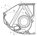
空気調和機においては、例えば、図2で示すような室内機の本体1上部の吸込口2と、同本体1下部の吹出口3とを結ぶ空気通路に熱交換器4aおよび4bと、同熱交換器4aおよび4bで熱交換された空気を室内へ送出する送風ファン5とを設け、前記吹出口3に室内への吹出風を左右に偏向する複数の板状の左右風向板6を回動自在に軸支するとともに、これら左右風向板群を連結板により回動自在に連結した構成になっている。
【0003】
ところで、送風ファン5からの吹出風は吹出口3に向かって直進するので、これを図7に示すような方向に回動させた複数の左右風向板6によって偏向しようとすると、吹出風がより多く当たる面は圧力面となり吹出風が偏向されるが、その裏側では風量が少なく負圧面となり、渦が起こり、この渦に室内空気が巻き込まれて表裏に温度差を生じ、冷房時はそこに結露が起こるという問題がある。
【0004】
このような結露を防止するようにした風向調節装置としては(例えば、特許文献1参照)があるが、構成が複雑で、組立にも時間を要し、コスト的にも問題があった。
【0005】
【特許文献1】
特開平11ー173652号公報(第4頁、第12図)
【0006】
【発明が解決しようとする課題】
本発明においては、上記の問題点に鑑み、より簡単な構成にして、且つ結露を防止できるようにした風向調節装置を備えた空気調和機を提供することを目的としている。
【0007】
【課題を解決するための手段】
本発明は上記の課題を解決するためになされたもので、第1の手段として、本体に設けた吸込口と吹出口とを結ぶ空気通路に熱交換器と送風ファンとを設け、前記吹出口に室内への吹出風を左右に偏向する複数の左右風向板を回動自在に設けると共に、これら左右風向板群を連結板により回動自在に連結してなる空気調和機において、隣合う一対の前記左右風向板の前後端間を対称な湾曲に形成すると共に、双方の上端又は下端中央に前記連結板に連結する連結軸と回転軸を備えたL字状の連結体を一体かつ対称に形成してなる構成とする。
【0009】
【発明の実施の形態】
以下、本発明の実施の形態を図1〜図6に基づいて説明する。
図1は空気調和機の室内機の一例を示す斜視図であり、図2は同室内機の内部構成を示す側断面図、図3および図4は第1の実施の形態を示す要部斜視図および動作説明図、図5および図6は第2の実施の形態を示す要部斜視図および動作説明図である。
【0010】
図において、1は空気調和機の室内機本体、2は同室内機本体1の上部に設けられた室内空気の吸込口、3は同室内機本体1の下部に設けられた吹出口で、前記吸込口2と吹出口3を結ぶ空気通路には熱交換器4aおよび4bと、同熱交換器4aおよび4bで熱交換された空気を吹出口3に向けて送出する送風ファン5が設けられ、吹出口3にはその天井側に回動自在に軸支され、送風ファン5からの吹出風を左右に偏向する複数の左右風向板6が設けられ、この左右風向板群は後述する連結板によって回動自在に連結された構成になっている。なお、左右風向板群の前方には室内への吹出風を上下に偏向する上下風向板(図示省略)が設けられている。
【0011】
左右風向板6は図3および図4に示すように、隣合う一対の左右風向板(6ー6)の前後端間を対称な湾曲に形成したものになっており、隣合う一対の左右風向板同士(6ー6)の上端中央部と、これら左右風向板群の後方上部の左右方向に設けられる連結板7との間に、後述する連結体8A、8Bを設けた構成になっている。
【0012】
連結体8A、8Bは平面L字状で対称をなし、何れもその一端が、対向する左右風向板(6ー6)の上端面中央部から延出させた形でそれぞれ一体に形成され、他端上面に前記連結板7に回動自在に連結される連結軸8aを有し、前記L字状のコーナ部上面に左右風向板(6ー6)をそれぞれ回動自在に軸支する回転軸8bを備えたものになっている。
【0013】
上記構成によれば、回転軸8bが左右風向板6の上端から離れた位置にあるため、吹出風を直進させるときは、左右風向板(6ー6)が図4の(A)に示すような横並びの対称位置となるが、吹出風を左方向に偏向させるときは、左右風向板(6ー6)が図4の(B)に示すような位置に回動し、また、吹出風を右方向に偏向させるときは、左右風向板(6ー6)が図4の(C)に示すような位置に回動して非対称となり、左右風向板6先端部近傍での渦と、この渦による室内空気の巻き込みが起き難くなり、結露しなくなる。
【0014】
図5および図6は第2の実施の形態を示したもので、先に説明した第1の実施の形態との違いは隣合う一対の左右風向板(6ー6)と連結板7との間に設ける連結体8Cだけである。
この連結体8Cは、平面T字状でその左右両端が、隣合う一対の左右風向板(6ー6)の上端面中央部間に一体に形成され、他端上面に前記連結板7に回動自在に連結される連結軸8aを有し、前記T字状の分岐点上面に左右風向板(6ー6)を回動自在に軸支する回転軸8bを備えたものになっている。
【0015】
このような構成であれば左右風向板(6ー6)とその連結体8Cとを一度に形成することができ、また、一体化されているので従来の風向調節装置に比して組立が簡単に行える。なお、動作および機能においては、前者と似通っているので説明は省略する。
【0016】
【発明の効果】
以上説明したような構成からなる左右風向板を有する空気調和機であれば、吹出風を左右に偏向しても、吹出口で空気抵抗が生じて送風の効率が低下したり、左右風向板に結露が発生するようなことはなく、品質および快適性が向上するにも係わらず、構成が単純であるためコストアップの恐れもない。
【図面の簡単な説明】
【図1】本発明に係わる空気調和機の室内機の外観斜視図である。
【図2】本発明および従来例に係わる室内機の内部構成を示す側断面図である。
【図3】本発明の第1の実施の形態を示す風向調節装置の要部斜視図である。
【図4】本発明の第1の実施の形態による動作機能の説明図で、(A)は吹出風が直進のとき、(B)は吹出風が左方向に偏向されたとき、(C)は吹出風が右方向に偏向されたときである。
【図5】本発明の第2の実施の形態を示す風向調節装置の要部斜視図である。
【図6】本発明の第2の実施の形態による動作機能の説明図で、(A)は吹出風が直進のとき、(B)は吹出風が左方向に偏向されたとき、(C)は吹出風が右方向に偏向されたときである。
【図7】従来例を示す空気調和機の送風ファンと左右風向板の関係説明図である。
【符号の説明】
1 室内機本体
2 吸込口
3 吹出口
4a、4b 熱交換器
5 送風ファン
6 左右風向板
7 連結板
8A、8B、8C 連結体
8a 連結軸
8b 回転軸[0001]
BACKGROUND OF THE INVENTION
The present invention relates to an air conditioner, and more particularly, to a wind direction adjusting device that deflects air blown into a room left and right.
[0002]
[Prior art]
In the air conditioner, for example, the
[0003]
By the way, since the blown air from the
[0004]
There is a wind direction adjusting device that prevents such dew condensation (see, for example, Patent Document 1), but the configuration is complicated, time is required for assembly, and there is a problem in cost.
[0005]
[Patent Document 1]
Japanese Patent Application Laid-Open No. 11-173652 (page 4, FIG. 12)
[0006]
[Problems to be solved by the invention]
In view of the above problems, an object of the present invention is to provide an air conditioner including a wind direction adjusting device that has a simpler configuration and can prevent condensation.
[0007]
[Means for Solving the Problems]
The present invention has been made to solve the above problems, and as a first means, a heat exchanger and a blower fan are provided in an air passage connecting a suction port and a blower outlet provided in the main body, and the blower outlet is provided. In an air conditioner in which a plurality of left and right wind direction plates for deflecting the air blown into the room to the left and right are pivotably connected, and the left and right wind direction plate groups are pivotally connected by a connecting plate. Formed symmetrically between the front and rear ends of the left and right wind direction plates, and integrally and symmetrically formed an L-shaped connecting body having a connecting shaft and a rotating shaft connected to the connecting plate at the upper end or the lower end center of both. The configuration is as follows.
[0009]
DETAILED DESCRIPTION OF THE INVENTION
Hereinafter, embodiments of the present invention will be described with reference to FIGS.
FIG. 1 is a perspective view showing an example of an indoor unit of an air conditioner, FIG. 2 is a side sectional view showing an internal configuration of the indoor unit, and FIGS. 3 and 4 are perspective views of a main part showing a first embodiment. FIGS. 5 and 6 are a perspective view and an operation explanatory diagram of a main part showing a second embodiment.
[0010]
In the figure, 1 is an indoor unit body of an air conditioner, 2 is an air inlet for indoor air provided in the upper part of the
[0011]
As shown in FIGS. 3 and 4, the left and right
[0012]
The
[0013]
According to the above configuration, since the
[0014]
5 and 6 show the second embodiment. The difference from the first embodiment described above is that the pair of left and right wind direction plates (6-6) and the connecting
The
[0015]
With such a configuration, the left and right wind direction plates (6-6) and the connecting
[0016]
【The invention's effect】
In the case of an air conditioner having a left and right wind direction plate having the configuration described above, even if the blown air is deflected to the left and right, air resistance is generated at the air outlet and air blowing efficiency is reduced, or the left and right wind direction plates are Condensation does not occur, and although the quality and comfort are improved, the structure is simple and there is no risk of cost increase.
[Brief description of the drawings]
FIG. 1 is an external perspective view of an indoor unit of an air conditioner according to the present invention.
FIG. 2 is a side sectional view showing an internal configuration of an indoor unit according to the present invention and a conventional example.
FIG. 3 is a perspective view of the main part of the wind direction adjusting device showing the first embodiment of the present invention.
FIGS. 4A and 4B are explanatory diagrams of an operation function according to the first embodiment of the present invention, in which FIG. 4A is a view when the blowing wind is straight, FIG. 4B is a view when the blowing wind is deflected to the left, and FIG. Is when the blowing wind is deflected to the right.
FIG. 5 is a perspective view of a main part of a wind direction adjusting device showing a second embodiment of the present invention.
6A and 6B are explanatory diagrams of operation functions according to the second embodiment of the present invention, in which FIG. 6A is a view when the blowing wind is straight, FIG. 6B is a drawing when the blowing wind is deflected to the left, and FIG. Is when the blowing wind is deflected to the right.
FIG. 7 is a diagram illustrating the relationship between a blower fan and left and right wind direction plates of an air conditioner showing a conventional example.
[Explanation of symbols]
DESCRIPTION OF
Claims (1)
Priority Applications (1)
| Application Number | Priority Date | Filing Date | Title |
|---|---|---|---|
| JP2003050262A JP3975943B2 (en) | 2003-02-27 | 2003-02-27 | Air conditioner |
Applications Claiming Priority (1)
| Application Number | Priority Date | Filing Date | Title |
|---|---|---|---|
| JP2003050262A JP3975943B2 (en) | 2003-02-27 | 2003-02-27 | Air conditioner |
Publications (2)
| Publication Number | Publication Date |
|---|---|
| JP2004257674A JP2004257674A (en) | 2004-09-16 |
| JP3975943B2 true JP3975943B2 (en) | 2007-09-12 |
Family
ID=33115724
Family Applications (1)
| Application Number | Title | Priority Date | Filing Date |
|---|---|---|---|
| JP2003050262A Expired - Fee Related JP3975943B2 (en) | 2003-02-27 | 2003-02-27 | Air conditioner |
Country Status (1)
| Country | Link |
|---|---|
| JP (1) | JP3975943B2 (en) |
Families Citing this family (5)
| Publication number | Priority date | Publication date | Assignee | Title |
|---|---|---|---|---|
| KR101195562B1 (en) * | 2007-07-10 | 2012-10-29 | 삼성전자주식회사 | Air conditioner |
| JP2010085070A (en) * | 2008-10-03 | 2010-04-15 | Hitachi Appliances Inc | Air conditioner |
| JP5267373B2 (en) * | 2009-08-05 | 2013-08-21 | パナソニック株式会社 | Air conditioner wind direction change device |
| CN104296347A (en) * | 2014-10-05 | 2015-01-21 | 刘健萍 | Novel air ducting device of air conditioner |
| CN108087964A (en) * | 2016-11-22 | 2018-05-29 | 苏州三星电子有限公司 | A kind of regulating device and air-cooled ducted air conditioner of controllable air-cooled ducted air conditioner outlet air trend |
-
2003
- 2003-02-27 JP JP2003050262A patent/JP3975943B2/en not_active Expired - Fee Related
Also Published As
| Publication number | Publication date |
|---|---|
| JP2004257674A (en) | 2004-09-16 |
Similar Documents
| Publication | Publication Date | Title |
|---|---|---|
| JP2002061944A (en) | Decoration panel of air conditioner, supply opening unit, and air conditioner | |
| JP2004245482A (en) | Separate type air-conditioner | |
| JP3975943B2 (en) | Air conditioner | |
| JP3052949B1 (en) | Air conditioner indoor unit | |
| JP2001304609A (en) | Indoor unit of air conditioner | |
| JP2000234796A (en) | Air conditioner | |
| JP2001324159A (en) | Indoor unit of air conditioner | |
| JP3596422B2 (en) | Indoor unit of air conditioner | |
| JP3203131B2 (en) | Air conditioner | |
| JP2001311530A (en) | Indoor unit for air-conditioner | |
| JP4391575B1 (en) | Embedded ceiling air conditioner | |
| JP3894129B2 (en) | Floor-mounted air conditioner | |
| JP3589803B2 (en) | Indoor unit for air conditioner | |
| JP3608238B2 (en) | Air conditioner indoor unit | |
| JP2940508B2 (en) | Ceiling-mounted air conditioner | |
| JP3784488B2 (en) | Air conditioner and ceiling-embedded air conditioner | |
| JPH0734272Y2 (en) | Air conditioner | |
| JPH10339470A (en) | Indoor machine for air conditioner | |
| JP3178579B2 (en) | Air conditioner | |
| JPH09229403A (en) | Air conditioner | |
| JP2005055138A (en) | Air conditioner | |
| JPH0835719A (en) | Air conditioner | |
| JPH08614Y2 (en) | Air conditioner heat exchanger | |
| WO2022097316A1 (en) | Ceiling-embedded air conditioner indoor unit | |
| JPH0623857Y2 (en) | Air conditioner outdoor unit |
Legal Events
| Date | Code | Title | Description |
|---|---|---|---|
| A621 | Written request for application examination |
Free format text: JAPANESE INTERMEDIATE CODE: A621 Effective date: 20051130 |
|
| A977 | Report on retrieval |
Free format text: JAPANESE INTERMEDIATE CODE: A971007 Effective date: 20070207 |
|
| A131 | Notification of reasons for refusal |
Free format text: JAPANESE INTERMEDIATE CODE: A131 Effective date: 20070220 |
|
| A521 | Written amendment |
Free format text: JAPANESE INTERMEDIATE CODE: A523 Effective date: 20070420 |
|
| TRDD | Decision of grant or rejection written | ||
| A01 | Written decision to grant a patent or to grant a registration (utility model) |
Free format text: JAPANESE INTERMEDIATE CODE: A01 Effective date: 20070529 |
|
| A61 | First payment of annual fees (during grant procedure) |
Free format text: JAPANESE INTERMEDIATE CODE: A61 Effective date: 20070611 |
|
| FPAY | Renewal fee payment (event date is renewal date of database) |
Free format text: PAYMENT UNTIL: 20100629 Year of fee payment: 3 |
|
| FPAY | Renewal fee payment (event date is renewal date of database) |
Free format text: PAYMENT UNTIL: 20110629 Year of fee payment: 4 |
|
| FPAY | Renewal fee payment (event date is renewal date of database) |
Free format text: PAYMENT UNTIL: 20110629 Year of fee payment: 4 |
|
| FPAY | Renewal fee payment (event date is renewal date of database) |
Free format text: PAYMENT UNTIL: 20120629 Year of fee payment: 5 |
|
| FPAY | Renewal fee payment (event date is renewal date of database) |
Free format text: PAYMENT UNTIL: 20130629 Year of fee payment: 6 |
|
| FPAY | Renewal fee payment (event date is renewal date of database) |
Free format text: PAYMENT UNTIL: 20140629 Year of fee payment: 7 |
|
| S531 | Written request for registration of change of domicile |
Free format text: JAPANESE INTERMEDIATE CODE: R313532 |
|
| R350 | Written notification of registration of transfer |
Free format text: JAPANESE INTERMEDIATE CODE: R350 |
|
| LAPS | Cancellation because of no payment of annual fees |