JP3973945B2 - Reel seat - Google Patents
Reel seat Download PDFInfo
- Publication number
- JP3973945B2 JP3973945B2 JP2002085963A JP2002085963A JP3973945B2 JP 3973945 B2 JP3973945 B2 JP 3973945B2 JP 2002085963 A JP2002085963 A JP 2002085963A JP 2002085963 A JP2002085963 A JP 2002085963A JP 3973945 B2 JP3973945 B2 JP 3973945B2
- Authority
- JP
- Japan
- Prior art keywords
- fishing rod
- reel
- cylinder member
- outer cylinder
- main body
- Prior art date
- Legal status (The legal status is an assumption and is not a legal conclusion. Google has not performed a legal analysis and makes no representation as to the accuracy of the status listed.)
- Expired - Fee Related
Links
- 239000011120 plywood Substances 0.000 description 12
- 239000000463 material Substances 0.000 description 7
- 230000002093 peripheral effect Effects 0.000 description 6
- KAKZBPTYRLMSJV-UHFFFAOYSA-N Butadiene Chemical compound C=CC=C KAKZBPTYRLMSJV-UHFFFAOYSA-N 0.000 description 2
- PPBRXRYQALVLMV-UHFFFAOYSA-N Styrene Chemical compound C=CC1=CC=CC=C1 PPBRXRYQALVLMV-UHFFFAOYSA-N 0.000 description 2
- NLHHRLWOUZZQLW-UHFFFAOYSA-N Acrylonitrile Chemical compound C=CC#N NLHHRLWOUZZQLW-UHFFFAOYSA-N 0.000 description 1
- 229920000049 Carbon (fiber) Polymers 0.000 description 1
- 241000276420 Lophius piscatorius Species 0.000 description 1
- 239000004677 Nylon Substances 0.000 description 1
- 229920000122 acrylonitrile butadiene styrene Polymers 0.000 description 1
- 239000004917 carbon fiber Substances 0.000 description 1
- 230000000694 effects Effects 0.000 description 1
- VNWKTOKETHGBQD-UHFFFAOYSA-N methane Chemical compound C VNWKTOKETHGBQD-UHFFFAOYSA-N 0.000 description 1
- 229920001778 nylon Polymers 0.000 description 1
- -1 polybutylene terephthalate Polymers 0.000 description 1
- 229920001707 polybutylene terephthalate Polymers 0.000 description 1
- 239000011347 resin Substances 0.000 description 1
- 229920005989 resin Polymers 0.000 description 1
Images


Classifications
-
- A—HUMAN NECESSITIES
- A01—AGRICULTURE; FORESTRY; ANIMAL HUSBANDRY; HUNTING; TRAPPING; FISHING
- A01K—ANIMAL HUSBANDRY; AVICULTURE; APICULTURE; PISCICULTURE; FISHING; REARING OR BREEDING ANIMALS, NOT OTHERWISE PROVIDED FOR; NEW BREEDS OF ANIMALS
- A01K87/00—Fishing rods
- A01K87/06—Devices for fixing reels on rods
-
- A—HUMAN NECESSITIES
- A01—AGRICULTURE; FORESTRY; ANIMAL HUSBANDRY; HUNTING; TRAPPING; FISHING
- A01K—ANIMAL HUSBANDRY; AVICULTURE; APICULTURE; PISCICULTURE; FISHING; REARING OR BREEDING ANIMALS, NOT OTHERWISE PROVIDED FOR; NEW BREEDS OF ANIMALS
- A01K89/00—Reels
Landscapes
- Life Sciences & Earth Sciences (AREA)
- Environmental Sciences (AREA)
- Animal Husbandry (AREA)
- Biodiversity & Conservation Biology (AREA)
- Marine Sciences & Fisheries (AREA)
- Fishing Rods (AREA)
Description
【0001】
【発明の属する技術の分野】
この発明は、釣竿に装着して使用するリールを支持するためのリールシートの構造に関するものである。
【0002】
【従来の技術および発明が解決しようとする課題】
図6は、従来の釣竿のリールシート部分を示す図である。
【0003】
この釣竿1では、釣竿本体2がグリップ3に挿通支持されており、グリップ3にはリールシート4が設けられている。グリップ3は、フロントグリップ5およびリアグリップ6を有し、リールシート4はこれらの間に配設されている。フロントグリップ5およびリアグリップ6には、それぞれフード8,9が設けられており、フロントグリップ5が矢印7の方向に沿ってスライドすることができるようになっている。そして、リールの脚部をリールシート4のリール載置面10に当接させた状態でフロントグリップ5をリールシート4側へスライドさせると、フード8,9間にリールの脚部が挟持され、リールは支持されるようになっている。
【0004】
図7は、図6におけるA−A断面図であり、リールシート4の断面構造を示している。
【0005】
同図に示すように、リールシート4は、円筒状の部材の一部を軸方向に切断して形成されており、この切断面が上記リール載置面10を構成している。なお、参照符号11は、釣竿本体2を支持するスリーブを示している。
【0006】
このようにしてリール載置面10を形成すると、当然にリール載置面10の肉厚tが薄くなる。しかも、釣竿1に付加価値を付けて商品性を向上させるために、リールシート4をたとえばプライウッド等により構成したい場合があるが、プライウッド等は温度変化に対する強度が低い。そのため、たとえば室内で釣竿を準備し、それを寒冷地の屋外(釣り場)で使用した場合等には、その温度変化によって上記肉厚tの部分が破損(割れ)してしまうおそれがある。
【0007】
加えて、釣竿1の操作性等(握り易さ等)を考慮すれば、リールシート4の外径寸法Dの範囲は自ずと決定されることから、釣竿本体2の外径をあまり大きくすることができない。なぜなら、リールシート4の外径Dが決まれば、釣竿本体2の外径を大きくすると上記肉厚tがきわめて薄くなってしまうからである。
【0008】
つまり、従来においては、手触りや高級感等の付加価値を付けるためにリールシート4をプライウッド等により構成したいという要請があるが、そのためにリールシートが損傷するおそれがあると共に、外径の大きい釣竿本体を採用することが事実上不可能であるという不都合があった。
【0009】
そこで、本発明の目的は、プライウッド等の機械的強度の低い材質で構成しつつ、その損傷を防止して外径の大きい釣竿本体にも適用することができるリールシートを提供することである。
【0010】
【課題を解決するための手段】
(1) リールシートが上述のように損傷する原因は、プライウッド等の機械的強度の低い材質で構成したこと、および釣竿本体を挿通支持するために肉厚が薄くなってしまい、そのために当該薄肉部分に大きな応力が生じてしまうことに起因することは明らかである。そのため本願発明者は、リールシートの形状ないし構造において、そもそも大きな応力が発生する薄肉部分を無くすことができれば、リールシートの損傷という不都合は起こり得ないと考えた。
【0014】
(2) そこで、本願に係る釣竿は、釣竿本体、この釣竿本体が挿通されるフロントグリップ及びリアグリップ並びにこのフロントグリップとリアグリップとの間に設けられておりその断面がC字状を呈しておりこの釣竿本体に嵌め込まれている外筒部材を備えており、このフロントグリップとこのリアグリップとの間にある釣竿本体のうち、この外筒部材の間隙に露出した部分が載置面を形成しており、この外筒部材とこの載置面とによってリールシートが構成されることを特徴とするものである。
【0015】
この構成によれば、釣用リールの脚部を載置面に載置することによって、釣用リールを装着することができる。このとき、釣竿本体はフロントグリップ及びリアグリップにより支持されており、釣用リールの脚部は釣竿本体の外面上に載置されることになる。また、外筒部材は釣竿本体に嵌め込まれているのみであり、外筒部材は釣竿本体の外面を装飾する部材として機能する。
【0016】
したがって、外筒部材は釣竿本体を支持する機能を有しないため、剛性等の機械的強度を担保する必要がなく、きわめて薄肉に形成することができる。しかも、外筒部材は間隙が設けられた断面C字状に形成されており、いわゆる開断面形状となっていることから、温度変化による変形が容易であり、大きな応力が発生することがない。
【0017】
(3) 特に、上記外筒部材の間隙の幅寸法を、釣用リールの脚部を間隙に嵌め込むことができる寸法に設定することができる。
【0018】
このようにすれば、釣用リールの脚部を載置面に載置した状態で、当該脚部と外筒部材との干渉を避けることができる。これにより、外筒部材の損傷等を確実に防止することができる。
【0020】
かかる構成の釣竿では、上述したように、リールシート部分にプライウッド等の機械的強度の低い材質を採用してもその損傷を防止することができ、また、外径の大きい釣竿本体を採用することができる。
【0021】
【発明の実施の形態】
以下、本発明の実施の形態について説明する。
<第1の実施形態>
図1は、本発明の第1の実施形態に係る釣竿10の要部拡大正面図である。
【0022】
この釣竿10は、たとえばルアーロッドとして構成されており、釣竿本体11と、グリップ12と、リールシート13とを備えている。
【0023】
グリップ12は、実釣時において釣人が把持する部分であって、フロントグリップ14およびリアグリップ15を備えている。そして、これらの間にリールシート13が設けられている。このリールシート13は、釣用のリール(図示せず)を装着・固定するためのものである。
【0024】
フロントグリップ14の後端およびリアグリップ15の先端にはそれぞれ、リールの脚部の前方側および後方側を固定するためのフロントフード16およびリアフード17が設けられている。つまり、リールシート13は、これらフロントフード16およびリアフード17によって挟み込まれるようにして配設されている。また、リアグリップ15の先端部にはねじ軸部18が形成されており、この部分にナット19,20が螺合されている。
【0025】
このため、ナット19を所定方向へ回転させると、リアフード17がリールシート13側へスライドするようになっている。したがって、リールシート13にリールの脚部を載置した状態でナット19を回転させることによって、フロントフード16とリアフード17とによってリールの脚部を挟持することができるようになっている。また、ナット19を反所定方向へ回転させることによってリアフード17をリールシート13と反対側へスライドさせることができるので、リールをリールシート13から取り外すことができる。なお、ナット20は、ナット19の緩みを防止するロックナットとして機能している。これらナット19,20の外周面には、滑り止めのためのローレットを形成することもできる。
【0026】
釣竿本体11は、フロントグリップ14側からグリップ12の内部に挿通されて支持されている。釣竿本体11は、細長棒状に形成され、たとえばカーボン繊維を筒状に形成する等、公知の要領で製造することができる。なお、図示していないが、釣竿本体11の所要の位置には、釣糸を案内するガイド部材が適宜配設されている。
【0027】
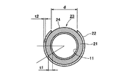
図2は、釣竿10の要部拡大斜視図であり、リールシート13の構造を詳細に示している。また、図3は、図2におけるB−B断面図である。
【0028】
これらの図に示すように、リールシート13は二重の筒状に形成されており、内筒部材(リール載置部)21と、外筒部材(筒状部材)22とを備えている。
【0029】
内筒部材21は、図に示すような断面円形の部材であって、たとえばナイロン、ポリブチレンテレフタレート、アクリロニトリル/ブタジエン/スチレン樹脂(ABS樹脂)等により形成することができる。この内筒部材21の両端は、上記フロントグリップ15およびリアグリップ16に連結されている。上記釣竿本体11は、この内筒部材21に挿通され支持されている。
【0030】
外筒部材22は、図に示すような断面C字状に形成されている。すなわち、外筒部材22は、全体として円筒状に形成されているが、軸方向に沿って間隙23が形成されている。この間隙23は、外筒部材22の径方向に貫通している。この外筒部材22は、内筒部材21の外側に嵌め込まれている。したがって、上記間隙23部分には、内筒部材21の外周面が露出している。そして、この外周面によって、リールの脚部が当接・載置される載置面24が構成されている。
【0031】
なお、内筒部材21の外周面の一部を特別の形状に形成し、この部分を載置面として構成することもできる。この場合、「特別の形状」とは、外周面の曲率半径を特定の数値に設定し、リールの脚部を載置しやすく形成すること等が考えられる。そして、その場合には、載置面と外筒部材22の間隙23とが対向するように、当該外筒部材23を内筒部材21に取り付けることができる。
【0032】
外筒部材22の間隙23の幅寸法dは、15mm〜17mmに設定することができる。もっとも、この寸法dはなんら限定される必要はないが、あえてかかる寸法に設定することによって、一般に市販されているすべてのリールの脚部が、この間隙23に嵌め込むことができるという利点がある。
【0033】
外筒部材22は、プライウッド等により構成されている。もっとも、外筒部材22の材質はなんら限定される必要はないが、プライウッド等を採用して外筒部材22を木製とすることによって、リールシート13自体を高級感のあるものに仕上げることができるという利点がある。
【0034】
本実施形態に係る釣竿10では、次のようにしてリールを取り付けることができる。
【0035】
図1および図2を参照して説明する。まず、ナット19,20を回転させて、フロントフード16とリアフード17との距離を大きくする。そして、リールの脚部を上記載置面24上に当接させ、その状態でナット19,20を締め込む。これにより、フロントフード16とリアフード17との間でリールの脚部が挟持され、リールが釣竿10に装着される。
【0036】
このとき、釣竿本体11は内筒部材21によって支持され、外筒部材22は内筒部材21を囲繞するように取り付けられているのみである。つまり、外筒部材22は、内筒部材21の外面を装飾する部材として機能している。
【0037】
したがって、内筒部材21は、その外観の善し悪しを特に考慮することなく釣竿本体11を確実に支持するという機能を確保することのみに重点をおいて設計することができる。たとえば、本実施形態では、内筒部材を上記材料で構成しているから、内筒部材21の肉厚t1は、0.5mm〜1.0mmという薄肉に設定することができる。
【0038】
また、外筒部材22については、釣竿本体11を支持する機能を有しないため剛性等の機械的強度を担保する必要がなく、きわめて薄肉に形成することができる。本実施形態では、外筒部材22の肉厚t2は、1.5mm〜3.0mmに設定することができる。しかも、外筒部材22は、図に示すような断面C字状に形成されており、いわゆる開断面形状となっている。このため、外筒部材22は、温度変化による変形が容易であり、大きな応力が発生することがない。すなわち、従来のように、外筒部材を閉断面形状とすると、肉厚の薄い部分に大きな応力が発生していたが、本実施形態のように、外筒部材22を開断面形状とすることによって、そのような大きな応力が発生する薄肉部分が存在しない。
【0039】
その結果、外筒部材の肉厚t2を上述のようにきわめて薄肉に設定したとしても、外筒部材22に亀裂等が生じることがない。また、内筒部材21の肉厚t1を上述のように設定することができるので、支持する釣竿本体11の外径を大きくすることができる。詳述すると、釣竿10の操作性等を考慮した場合、リールシート13部分全体の外径寸法は、一定の範囲内に限定されてしまうので、内筒部材21の外径も一定の寸法以下に制限されてしまう。しかし、内筒部材21の肉厚t1を薄くすることによって、相対的に大径の釣竿本体11を挿通支持することが可能となる。
【0040】
よって、本実施形態に係る釣竿10では、リールシート13の強度設計において内筒部材21を機械的強度の高い材料を選定することにより、リールシート13全体の外径を小さくすることが可能であり、デザイン上の自由度が向上する。しかも、外筒部材22は開断面形状を呈しているから温度変化等による破損のおそれがなく、外筒部材22をたとえばプライウッド等により構成することができるので、リールシート13を手触りの良い高級感のあるものに仕上げることができる。
【0041】
特に本実施形態では、外筒部材22の間隙23の幅寸法dを上述の寸法に設定し、リールの脚部を間隙23に嵌め込むようにしているので、リールの脚部と外筒部材22との干渉を避けることができ、これにより、筒状部材の損傷等を確実に防止することができる。しかも、リールの装着位置を低く、すなわち、装着したリールの位置を釣竿10の中心に近づけることができるので、実釣における釣竿10の操作性を向上させることができる。
<第2の実施形態>
次に、本発明の第2の実施形態について説明する。
【0042】
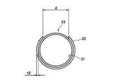
図4は、本発明の第2の実施形態に係る釣竿30の要部拡大正面部である。また、図5は、図4におけるB−B断面図である。
【0043】
本実施形態に係る釣竿30が上記第1の実施形態に係る釣竿10と異なるところは、釣竿10では、釣竿本体11を内筒部材21(図2参照)により支持する構造であるのに対し、釣竿30では、内筒部材21を設けずに、釣竿本体31をグリップ12によって支持する構造となっており、そのために、外筒部材32は、釣竿本体31に嵌め込まれている点である。なお、釣竿30のその他の構成については釣竿10と同様であるので、同様の参照符号を付してその説明を省略する。
【0044】
釣竿本体31は、図1で示した釣竿本体11よりも大径に構成されており、釣竿本体11と同様に製作することができる。本実施形態では、釣竿本体31はグリップ12によって支持されており、釣竿本体31の一部33がリールシート13の一部を構成している。
【0045】
すなわち、本実施形態では、釣竿本体31の一部33と、外筒部材32とによりリールシート13が構成されており、釣竿本体31の一部33の外周面が、リールを載置する載置面24を兼ねている。また、外筒部材32は、上記第1の実施形態で示したと同様に断面C字状に形成されており、プライウッド等を使用して構成することができる。
【0046】
本実施形態に係る釣竿30では、釣竿本体31がグリップ12により支持されており、リールシート13全体の外径を釣人が握りやすい寸法に設定しながら、釣竿本体31の外径をきわめて大きなものとすることができる。
【0047】
しかも、リールシート13には外筒部材32が設けられており、これが釣竿本体31に嵌め込まれているので、外筒部材32には機械的強度(剛性等)が要求されない。したがって、外筒部材32はきわめて薄肉に形成することができ、亀裂等が生じるおそれがない。
【0048】
よって、本実施形態に係る釣竿30では、リールシート13の設計においてデザイン上の自由度が向上する。しかも、外筒部材32は断面C字状を呈しているから温度変化等による破損のおそれがなく、外筒部材32をプライウッド等により構成した場合には、リールシート13を手触りの良い高級感のあるものに仕上げることができる。
【0049】
また、上記第1の本実施形態と同様に、外筒部材32の間隙23の幅寸法dを上述の寸法に設定し、リールの脚部を間隙23に嵌め込むようにしているので、リールの脚部と外筒部材22との干渉を避けることができ、これにより、筒状部材の損傷等を確実に防止することができる。しかも、リールの装着位置を低く、すなわち、装着したリールの位置を釣竿30の中心に近づけることができるので、実釣における釣竿30の操作性をさらに向上させることができる。
【0050】
【発明の効果】
以上のように本発明によれば、釣竿本体はリール載置部により支持され、これを筒状部材によって外観の装飾を行うことができる。したがって、リール載置部を機械的強度の高い材料で構成することにより、リール載置部の外径をそれほど大きくすることなく大径の釣竿本体をも支持することができるうえ、筒状部材も薄肉に形成することができる。
【0051】
その結果、リールシートの強度設計においてリールシート全体の外径を小さくすることが可能であり、デザイン上の自由度が向上する。しかも、筒状部材は開断面形状を呈しているから温度変化による破損のおそれがなく、筒状部材をたとえばプライウッド等により構成することができ、リールシートを手触りがよく高級感のあるものに仕上げることができる。
【図面の簡単な説明】
【図1】本発明の第1の実施形態に係る釣竿の要部拡大正面図である。
【図2】釣竿の要部拡大斜視図である。
【図3】図2におけるB−B断面図である。
【図4】本発明の第2の実施形態に係る釣竿の要部拡大正面図である。
【図5】図4におけるB−B断面図である。
【図6】従来の釣竿のリールシート部分を示す図である。
【図7】図6におけるA−A断面図である。
【符号の説明】
10 釣竿
11 釣竿本体
12 グリップ
13 リールシート
14 フロントグリップ
15 リアグリップ
21 内筒部材
22 外筒部材
23 溝
24 載置面
30 釣竿
31 釣竿本体
32 外筒部材
33 釣竿本体の一部[0001]
[Field of the Invention]
The present invention relates to a structure of a reel sheet for supporting a reel used by being mounted on a fishing rod.
[0002]
[Background Art and Problems to be Solved by the Invention]
FIG. 6 is a view showing a reel seat portion of a conventional fishing rod.
[0003]
In this fishing rod 1, a fishing rod
[0004]
FIG. 7 is a cross-sectional view taken along the line AA in FIG. 6 and shows a cross-sectional structure of the reel sheet 4.
[0005]
As shown in the figure, the reel sheet 4 is formed by cutting a part of a cylindrical member in the axial direction, and this cut surface constitutes the
[0006]
When the
[0007]
In addition, considering the operability of the fishing rod 1 (ease of gripping, etc.), the range of the outer diameter dimension D of the reel seat 4 is naturally determined, so that the outer diameter of the
[0008]
In other words, in the past, there is a demand for the reel sheet 4 to be made of plywood or the like in order to add value such as touch and luxury. However, the reel sheet may be damaged, and a fishing rod having a large outer diameter may be required. There was a disadvantage that it was practically impossible to adopt the main body.
[0009]
SUMMARY OF THE INVENTION An object of the present invention is to provide a reel sheet that is made of a material having low mechanical strength such as plywood and that can be applied to a fishing rod body having a large outer diameter while preventing damage.
[0010]
[Means for Solving the Problems]
(1) The reason why the reel sheet is damaged as described above is that it is made of a material with low mechanical strength such as plywood, and the thickness of the fishing rod is reduced because it is inserted and supported. It is clear that this is caused by the fact that a large stress is generated in the portion. For this reason, the inventor of the present application has considered that the inconvenience of damage to the reel sheet cannot occur if the thin portion where the large stress is generated can be eliminated in the reel sheet shape or structure.
[0014]
(2) Therefore, the fishing rod according to the present application is provided with a fishing rod main body, a front grip and a rear grip through which the fishing rod main body is inserted, and between the front grip and the rear grip. The outer cylinder member fitted in the fishing rod body is provided, and the portion of the fishing rod body between the front grip and the rear grip that is exposed in the gap between the outer cylinder members forms a mounting surface. The outer cylinder member and the placement surface constitute a reel sheet .
[0015]
According to this configuration, the fishing reel can be mounted by mounting the leg portion of the fishing reel on the mounting surface. At this time, the fishing rod main body is supported by the front grip and the rear grip, and the leg portion of the fishing reel is placed on the outer surface of the fishing rod main body. Further, the outer cylinder member is only fitted into the fishing rod main body , and the outer cylinder member functions as a member for decorating the outer surface of the fishing rod main body .
[0016]
Therefore, since the outer cylinder member does not have a function of supporting the fishing rod main body, it is not necessary to ensure mechanical strength such as rigidity and can be formed to be extremely thin. In addition, since the outer cylinder member is formed in a C-shaped cross section with a gap, and has a so-called open cross-sectional shape, the outer cylinder member is easily deformed due to a temperature change, and no large stress is generated.
[0017]
(3) In particular, the width of the gap of the outer cylinder member, the leg portion of the fishing reel can set Teisu Rukoto the dimensioned to fit in the gap.
[0018]
In this way, it is possible to avoid interference between the leg portion and the outer cylinder member in a state where the leg portion of the fishing reel is placed on the placement surface. Thereby, damage etc. of an outer cylinder member can be prevented reliably.
[0020]
In the fishing rod having such a configuration, as described above, even if a material with low mechanical strength such as plywood is used for the reel seat portion, the damage can be prevented, and a fishing rod main body having a large outer diameter should be adopted. Can do.
[0021]
DETAILED DESCRIPTION OF THE INVENTION
Embodiments of the present invention will be described below.
<First Embodiment>
FIG. 1 is an enlarged front view of a main part of a
[0022]
The
[0023]
The
[0024]
A
[0025]
For this reason, when the
[0026]
The
[0027]
FIG. 2 is an enlarged perspective view of the main part of the
[0028]
As shown in these drawings, the
[0029]
The
[0030]
The
[0031]
In addition, a part of outer peripheral surface of the
[0032]
The width d of the
[0033]
The
[0034]
In the
[0035]
This will be described with reference to FIGS. First, the nuts 19 and 20 are rotated to increase the distance between the
[0036]
At this time, the fishing rod
[0037]
Therefore, the
[0038]
Further, since the
[0039]
As a result, even if the thickness t2 of the outer cylinder member is set to be extremely thin as described above, the
[0040]
Therefore, in the
[0041]
In particular, in the present embodiment, the width dimension d of the
<Second Embodiment>
Next, a second embodiment of the present invention will be described.
[0042]
FIG. 4 is an enlarged front view of a main part of a
[0043]
The difference between the
[0044]
The fishing rod
[0045]
That is, in the present embodiment, the
[0046]
In the
[0047]
In addition, since the
[0048]
Therefore, in the
[0049]
Further, similarly to the first embodiment, the width d of the
[0050]
【The invention's effect】
As described above, according to the present invention, the fishing rod main body is supported by the reel mounting portion, and the appearance can be decorated by the cylindrical member. Therefore, by configuring the reel mounting portion with a material having high mechanical strength, it is possible to support a large-diameter fishing rod main body without enlarging the outer diameter of the reel mounting portion, and also a cylindrical member. It can be formed thin.
[0051]
As a result, it is possible to reduce the outer diameter of the entire reel sheet in the strength design of the reel sheet, and the degree of freedom in design is improved. In addition, since the cylindrical member has an open cross-sectional shape, there is no risk of damage due to temperature changes, and the cylindrical member can be made of, for example, plywood, and the reel sheet is finished with a good touch and high quality. be able to.
[Brief description of the drawings]
FIG. 1 is an enlarged front view of a main part of a fishing rod according to a first embodiment of the present invention.
FIG. 2 is an enlarged perspective view of a main part of a fishing rod.
FIG. 3 is a cross-sectional view taken along the line BB in FIG.
FIG. 4 is an enlarged front view of a main part of a fishing rod according to a second embodiment of the present invention.
5 is a cross-sectional view taken along the line BB in FIG.
FIG. 6 is a view showing a reel sheet portion of a conventional fishing rod.
7 is a cross-sectional view taken along line AA in FIG.
[Explanation of symbols]
DESCRIPTION OF
Claims (2)
このフロントグリップとこのリアグリップとの間にある釣竿本体のうち、この外筒部材の間隙に露出した部分が載置面を形成しており、Of the fishing rod body between this front grip and this rear grip, the part exposed in the gap of this outer cylinder member forms a mounting surface,
この外筒部材とこの載置面とによってリールシートが構成されることを特徴とする釣竿。A fishing rod characterized in that a reel seat is constituted by the outer cylinder member and the placement surface.
上記外筒部材の間隙の幅寸法は、釣用リールの脚部を間隙に嵌め込むことができる寸法に設定されていることを特徴とする釣竿。In fishing rod according to claim 1 Symbol placement,
A fishing rod characterized in that a width dimension of the gap of the outer cylinder member is set to a dimension capable of fitting a leg portion of a fishing reel into the gap.
Priority Applications (4)
| Application Number | Priority Date | Filing Date | Title |
|---|---|---|---|
| JP2002085963A JP3973945B2 (en) | 2002-03-26 | 2002-03-26 | Reel seat |
| TW092104081A TWI264277B (en) | 2002-03-26 | 2003-02-26 | Fastening seat for reel |
| CNB031213111A CN1309299C (en) | 2002-03-26 | 2003-03-25 | Fish wire reel base |
| KR1020030018488A KR100947807B1 (en) | 2002-03-26 | 2003-03-25 | Fishing rod |
Applications Claiming Priority (1)
| Application Number | Priority Date | Filing Date | Title |
|---|---|---|---|
| JP2002085963A JP3973945B2 (en) | 2002-03-26 | 2002-03-26 | Reel seat |
Publications (3)
| Publication Number | Publication Date |
|---|---|
| JP2003274811A JP2003274811A (en) | 2003-09-30 |
| JP2003274811A5 JP2003274811A5 (en) | 2005-06-16 |
| JP3973945B2 true JP3973945B2 (en) | 2007-09-12 |
Family
ID=28449281
Family Applications (1)
| Application Number | Title | Priority Date | Filing Date |
|---|---|---|---|
| JP2002085963A Expired - Fee Related JP3973945B2 (en) | 2002-03-26 | 2002-03-26 | Reel seat |
Country Status (4)
| Country | Link |
|---|---|
| JP (1) | JP3973945B2 (en) |
| KR (1) | KR100947807B1 (en) |
| CN (1) | CN1309299C (en) |
| TW (1) | TWI264277B (en) |
Families Citing this family (1)
| Publication number | Priority date | Publication date | Assignee | Title |
|---|---|---|---|---|
| JP6586054B2 (en) * | 2016-07-11 | 2019-10-02 | 真義 東村 | Lure rod |
Family Cites Families (10)
| Publication number | Priority date | Publication date | Assignee | Title |
|---|---|---|---|---|
| JP2506854Y2 (en) * | 1990-06-04 | 1996-08-14 | ダイワ精工株式会社 | Reel fixing device for fishing rod |
| US5291683A (en) * | 1990-07-20 | 1994-03-08 | Shimano Inc. | Fishing rod |
| JPH0555872U (en) * | 1992-01-07 | 1993-07-27 | 株式会社シマノ | Reel mounting structure for fishing rod |
| JPH06225671A (en) * | 1993-02-02 | 1994-08-16 | Daiwa Seiko Inc | Reel stem fixation device of fishing rod |
| JP2567038Y2 (en) * | 1992-09-04 | 1998-03-30 | 株式会社シマノ | fishing rod |
| JPH09205945A (en) * | 1996-01-31 | 1997-08-12 | Daiwa Seiko Inc | Fishing rod |
| JP3066321B2 (en) | 1996-06-20 | 2000-07-17 | 富士工業株式会社 | Reel seat for fishing rod |
| JPH11155431A (en) * | 1997-11-28 | 1999-06-15 | Mamiya Op Co Ltd | Reel seat structure for fishing rod and fishing rod with the same |
| US5996270A (en) * | 1998-08-10 | 1999-12-07 | Alley; F. William | Reel seat with machinable core |
| CN2462665Y (en) * | 2001-02-08 | 2001-12-05 | 崔普铉 | Reel base |
-
2002
- 2002-03-26 JP JP2002085963A patent/JP3973945B2/en not_active Expired - Fee Related
-
2003
- 2003-02-26 TW TW092104081A patent/TWI264277B/en not_active IP Right Cessation
- 2003-03-25 KR KR1020030018488A patent/KR100947807B1/en active IP Right Grant
- 2003-03-25 CN CNB031213111A patent/CN1309299C/en not_active Expired - Fee Related
Also Published As
| Publication number | Publication date |
|---|---|
| TWI264277B (en) | 2006-10-21 |
| KR100947807B1 (en) | 2010-03-15 |
| CN1309299C (en) | 2007-04-11 |
| CN1446460A (en) | 2003-10-08 |
| JP2003274811A (en) | 2003-09-30 |
| TW200304356A (en) | 2003-10-01 |
| KR20030077440A (en) | 2003-10-01 |
Similar Documents
| Publication | Publication Date | Title |
|---|---|---|
| KR100459310B1 (en) | Reel Seat for Fishing Rod | |
| JP7117987B2 (en) | Fishing rod reel seat nut, fishing rod reel seat and fishing rod | |
| JPH0642810B2 (en) | Reel fixing device | |
| JP3973945B2 (en) | Reel seat | |
| KR900003964Y1 (en) | Reel seat | |
| JP4037159B2 (en) | Reel seat | |
| JP3935753B2 (en) | Reel seat and fishing rod equipped with the same | |
| JP2017012065A (en) | Reel seat support structure and fishing rod having the same | |
| JP4507253B2 (en) | fishing rod | |
| JP7386149B2 (en) | fishing rod | |
| JP5018077B2 (en) | Brush cutter | |
| JP3948978B2 (en) | Reel seat and fishing rod | |
| JP3068726B2 (en) | Fishing rod reel seat mounting structure | |
| JP7094735B2 (en) | Reel seat | |
| JP3066321B2 (en) | Reel seat for fishing rod | |
| JP3654566B2 (en) | Fishing rod reel seat | |
| JP2001275523A (en) | Device for fixing reel leg of fishing rod | |
| KR20030021148A (en) | Reel seat | |
| JP3908066B2 (en) | Reel seat | |
| KR101044822B1 (en) | Fishing rod | |
| JP5817979B2 (en) | Reel seat and hood and operation nut used therefor | |
| JP3817136B2 (en) | Locking nut for glasses | |
| JP2008017792A (en) | Fishing rod | |
| JP6936094B2 (en) | fishing rod | |
| GB2628029A (en) | Fishing rod |
Legal Events
| Date | Code | Title | Description |
|---|---|---|---|
| A521 | Request for written amendment filed |
Free format text: JAPANESE INTERMEDIATE CODE: A523 Effective date: 20040914 |
|
| A621 | Written request for application examination |
Free format text: JAPANESE INTERMEDIATE CODE: A621 Effective date: 20040914 |
|
| RD04 | Notification of resignation of power of attorney |
Free format text: JAPANESE INTERMEDIATE CODE: A7424 Effective date: 20041101 |
|
| A977 | Report on retrieval |
Free format text: JAPANESE INTERMEDIATE CODE: A971007 Effective date: 20061228 |
|
| A131 | Notification of reasons for refusal |
Free format text: JAPANESE INTERMEDIATE CODE: A131 Effective date: 20070116 |
|
| A521 | Request for written amendment filed |
Free format text: JAPANESE INTERMEDIATE CODE: A523 Effective date: 20070301 |
|
| A131 | Notification of reasons for refusal |
Free format text: JAPANESE INTERMEDIATE CODE: A131 Effective date: 20070327 |
|
| A521 | Request for written amendment filed |
Free format text: JAPANESE INTERMEDIATE CODE: A523 Effective date: 20070514 |
|
| TRDD | Decision of grant or rejection written | ||
| A01 | Written decision to grant a patent or to grant a registration (utility model) |
Free format text: JAPANESE INTERMEDIATE CODE: A01 Effective date: 20070612 |
|
| A61 | First payment of annual fees (during grant procedure) |
Free format text: JAPANESE INTERMEDIATE CODE: A61 Effective date: 20070613 |
|
| R150 | Certificate of patent or registration of utility model |
Free format text: JAPANESE INTERMEDIATE CODE: R150 Ref document number: 3973945 Country of ref document: JP Free format text: JAPANESE INTERMEDIATE CODE: R150 |
|
| FPAY | Renewal fee payment (event date is renewal date of database) |
Free format text: PAYMENT UNTIL: 20100622 Year of fee payment: 3 |
|
| FPAY | Renewal fee payment (event date is renewal date of database) |
Free format text: PAYMENT UNTIL: 20100622 Year of fee payment: 3 |
|
| FPAY | Renewal fee payment (event date is renewal date of database) |
Free format text: PAYMENT UNTIL: 20110622 Year of fee payment: 4 |
|
| R250 | Receipt of annual fees |
Free format text: JAPANESE INTERMEDIATE CODE: R250 |
|
| FPAY | Renewal fee payment (event date is renewal date of database) |
Free format text: PAYMENT UNTIL: 20110622 Year of fee payment: 4 |
|
| FPAY | Renewal fee payment (event date is renewal date of database) |
Free format text: PAYMENT UNTIL: 20120622 Year of fee payment: 5 |
|
| R250 | Receipt of annual fees |
Free format text: JAPANESE INTERMEDIATE CODE: R250 |
|
| FPAY | Renewal fee payment (event date is renewal date of database) |
Free format text: PAYMENT UNTIL: 20120622 Year of fee payment: 5 |
|
| FPAY | Renewal fee payment (event date is renewal date of database) |
Free format text: PAYMENT UNTIL: 20130622 Year of fee payment: 6 |
|
| R250 | Receipt of annual fees |
Free format text: JAPANESE INTERMEDIATE CODE: R250 |
|
| R250 | Receipt of annual fees |
Free format text: JAPANESE INTERMEDIATE CODE: R250 |
|
| R250 | Receipt of annual fees |
Free format text: JAPANESE INTERMEDIATE CODE: R250 |
|
| R250 | Receipt of annual fees |
Free format text: JAPANESE INTERMEDIATE CODE: R250 |
|
| R250 | Receipt of annual fees |
Free format text: JAPANESE INTERMEDIATE CODE: R250 |
|
| R250 | Receipt of annual fees |
Free format text: JAPANESE INTERMEDIATE CODE: R250 |
|
| R250 | Receipt of annual fees |
Free format text: JAPANESE INTERMEDIATE CODE: R250 |
|
| R250 | Receipt of annual fees |
Free format text: JAPANESE INTERMEDIATE CODE: R250 |
|
| R250 | Receipt of annual fees |
Free format text: JAPANESE INTERMEDIATE CODE: R250 |
|
| LAPS | Cancellation because of no payment of annual fees |