JP3973762B2 - Alarm system - Google Patents
Alarm system Download PDFInfo
- Publication number
- JP3973762B2 JP3973762B2 JP16578798A JP16578798A JP3973762B2 JP 3973762 B2 JP3973762 B2 JP 3973762B2 JP 16578798 A JP16578798 A JP 16578798A JP 16578798 A JP16578798 A JP 16578798A JP 3973762 B2 JP3973762 B2 JP 3973762B2
- Authority
- JP
- Japan
- Prior art keywords
- sensor
- signal
- alarm
- alarm system
- smoke
- Prior art date
- Legal status (The legal status is an assumption and is not a legal conclusion. Google has not performed a legal analysis and makes no representation as to the accuracy of the status listed.)
- Expired - Fee Related
Links
Images


Classifications
-
- G—PHYSICS
- G08—SIGNALLING
- G08B—SIGNALLING OR CALLING SYSTEMS; ORDER TELEGRAPHS; ALARM SYSTEMS
- G08B17/00—Fire alarms; Alarms responsive to explosion
- G08B17/10—Actuation by presence of smoke or gases, e.g. automatic alarm devices for analysing flowing fluid materials by the use of optical means
- G08B17/103—Actuation by presence of smoke or gases, e.g. automatic alarm devices for analysing flowing fluid materials by the use of optical means using a light emitting and receiving device
- G08B17/107—Actuation by presence of smoke or gases, e.g. automatic alarm devices for analysing flowing fluid materials by the use of optical means using a light emitting and receiving device for detecting light-scattering due to smoke
-
- G—PHYSICS
- G08—SIGNALLING
- G08B—SIGNALLING OR CALLING SYSTEMS; ORDER TELEGRAPHS; ALARM SYSTEMS
- G08B29/00—Checking or monitoring of signalling or alarm systems; Prevention or correction of operating errors, e.g. preventing unauthorised operation
- G08B29/18—Prevention or correction of operating errors
- G08B29/185—Signal analysis techniques for reducing or preventing false alarms or for enhancing the reliability of the system
-
- G—PHYSICS
- G08—SIGNALLING
- G08B—SIGNALLING OR CALLING SYSTEMS; ORDER TELEGRAPHS; ALARM SYSTEMS
- G08B17/00—Fire alarms; Alarms responsive to explosion
- G08B17/10—Actuation by presence of smoke or gases, e.g. automatic alarm devices for analysing flowing fluid materials by the use of optical means
- G08B17/11—Actuation by presence of smoke or gases, e.g. automatic alarm devices for analysing flowing fluid materials by the use of optical means using an ionisation chamber for detecting smoke or gas
- G08B17/113—Constructional details
Description
【0001】
【発明の属する技術分野】
本発明は、周囲の状態センサーから受け取った電気信号の誤り検出に関し、特に、本発明は、煙や火災のような周囲状態を示す電気信号における非煙の変化による誤り警報を最小にする処理装置および方法に関する。
【0002】
【従来の技術】
警報状態の検出のためのいろいろなシステムは知られている。このようなシステムの1つの特定の形状は、共通の譲渡人に譲渡されたTice他に与えられた米国特許第4,916,423 号に示された形式の煙または火災検知システムであり、レファレンスによって、ここに取り込まれる。
このシステムの検出器の1つ以上からの入力を受け取ると、このシステムに関連した制御装置は、火災状態が関心のある1以上の領域に存在するか否かに関して判断をすることができる。いろいろな技術がこの判断をする目的のために、過去に用いられている。
光電煙感知器やイオン化型煙感知器のような煙のセンサーは、周囲の煙の検知されたレベルを示す出力を与えるように意図されている。周囲のノイズ、たとえば、各々の感知器に入ることができる埃の粒子や虫は、煙の存在と関連のない状態にあるセンサーからの出力信号に変化を生じる。これらのノイズの出力は、それぞれの感知器の感度が非常に高いならば、誤った警報を発生する。このような誤った警報は望ましくない。
【0003】
一般に、初期に警告をだすために用いられる光電煙センサーは、光源と光感知レシーバを用いる。光源、レシーバおよびバッフリングの設計および配置は、煙や他の粒子が光りビームの領域に存在しないかぎり、通常、光源から著しい光がレシーバに達しないものである。もし、煙や他の粒子がこの領域に存在するならば、それらは、光の光子を散乱し、いくらかの光がレシーバに到達するようにする。
初期に警告しない煙感知システムにおいては、警報を発生するためにセンサに必要な煙の濃度は、通常周りに存在する埃、ファイバーおよび他の煙でない粒子の濃度と比較して、かなり大きく、従って、これらのシステムは、これらの粒子によって生じた誤りの徴候に敏感でない。初期に警告する煙感知システムにおいては、煙の低いレベルによって得られた信号が、この形式のシステムが一般に用いられる環境において、空気で運ばれる煙でない粒子によって得られる信号と匹敵されるかも知れない。
【0004】
従来の早い警報システムにおいて、煙センサーに存在する空気中の非煙粒子を除去するために、フィルターが用いられた。一般に、フィルターの存在は、センサーがフィルターを通して空気を排出するファンあるいは他の手段を有することを必要とする。従来の感知器に用いられる機械的ファンやフィルターは、高価であり、定期的なメンテナンスを必要とする。
【0005】
【発明が解決しようとする課題】
ファンやフィルターを必要としない早い警報システムに用いることができる感知器の必要性がある。追加的な機械的要素を組み込む必要性をさけながら、誤りの徴候を最小にすることが、このようなシステムの経費を著しく増大することなく達成されることが好ましい。
【0006】
【課題を解決するための手段】
本発明による火災感知器および警報システムは、制御装置と多くの初期に警報する煙センサーを有する。これらの煙センサーの各々は、その領域における煙粒子の密度を測る。各々のセンサーは、煙濃度の電気的表示である信号を制御装置へ送る。この制御装置は、少なくとも幾つかのセンサーからの信号を処理し、警報状態にあるか否かを判断する。
煙でない空気によって運ばれる粒子によって引き起こされる誤りの指示は、拒否されなければならないので、システムが煙りの非常に低いレベルを検知するように設計される。
煙と繊維状の粒子、例えば、けばや糸くづあるいは人間の毛の間の識別能力は、本発明を具体化する以外に、システムの重大な利点である。制御装置において信号処理ソフトウェアと結合された、煙センサーの設計によって、本システムがこれらの繊維状粒子を検出することができる。この設計の特徴は、システムがこのような繊維の存在によって引き起こされる誤り警報を最小にする。
【0007】
本システムは、少なくとも2つの煙センサーが各部屋や囲まれた空間に据え付けられることが必要である。誤りの読み取りを生じる十分大きな繊維状の粒子は、単一の煙センサーに入る可能性は小さいが、重大である。このような粒子が同時に2つのセンサーに入る可能性は非常に小さいので、重大ではない。
制御装置が煙り警報を示す第1のセンサーからの信号を識別すると、それは、信号を解析し、読み取りが繊維状の粒子をも示しているか否かを判断する。もし、第1のセンサーからの読み取りが繊維状の粒子を示しているなら、制御装置は同じ部屋にあるとわかっている第2の感知器からの読み取りを解析する。
もし、所定の時間期間中に、煙の小さなレベルを示す、第2のセンサーからの読み取りが受信されないなら、制御装置は、第1のセンサーにおける信号が繊維状の粒子、あるいは他の幾らかの非煙現象によって生じたことの表示をする。メンテナンスやトラブルの信号を発生することができる。
【0008】
本発明の他の多くの利点や特徴は、本発明の以下の詳細な説明やその実施の形態、特許請求の範囲、および図面から容易に明らかになるであろう。
【0009】
【発明の実施の形態】
本発明は、多くの異なる形状の実施の形態ができるけれども、本願の開示が本発明の原理の説明として考慮されるべきであり、本発明を図示された特定の実施形態に限定する意図でないという理解で本発明の特定の実施形態を図面に示し、詳細に説明する。
図1は、本発明によるシステム10のブロック図を示す。このシステム10は、制御装置12を有し、この制御装置は、プログラム可能なプロセッサ14と記憶装置16で実現される。この記憶装置16は、プロセッサ14によって使用される制御プログラムとデータ記憶領域を有する。
制御装置12は、双方向通信リンク20によって、符号22で一般に示される複数の周囲の状態センサー、即ち感知器に接続される。複数の、例えばセンサー22a,22b,...22nのような数22は、隣接領域における特定の周囲の状態を検知するためである。システム10は出力のビジュアルディスプレイ装置15a及びオペレータ制御装置、即ちキーボード15bのような入力装置を有するオペレータディスプレイ装置も有する。
【0010】
制御装置12も複数のシステム出力を有する。これらの出力は、耳で聞いたり、目で見たりできる警報器を作動させるために用いられる。更に、制御装置12は、煙の移動を制御するように、ビルディングにおける通気、即ち空気取り扱いシステムに結合される。
代表的な形式の感知器は、イオン型あるいは光電型の煙感知器を有する。温度感知器ばかりでなく他の形式の周囲の状態センサーは、本発明によるシステムにおいて用いることができる。
特に、本システム10は、1つ以上の領域、例えば連続していても、あるいは連続していなくてもよい領域R1、R2をモニターする。2つ以上の感知器22-1,22-2,...22-kは、領域R1に配置される。検出器22-1'...22-k' 領域R2に配置される。領域R1、R2は、例えば実質的に閉じた部屋である。
【0011】
図2は、システム10と一緒に用いることができる感知器22iのブロック図の代表例である。この感知器22iは、センサー素子30を有する。この素子30は、特定の周囲の状態、例えば、煙、温度、赤外線放射等を感知し、ライン32上にそれらを示す電気システムを生成する。
図2を参照すると。ライン32を介して、センサー30からの出力が感知器の局部的な制御素子40に結合される。この制御素子40は、ディジタル回路か、アナログ回路のいずれかで実現される。ディジタル形状の場合、制御素子40は、ハードワイヤードロジックで実現されるか、プログラムされたマイクロプロセッサを組み込むことができる。この制御回路40は、インターフェース回路42を介して、システム制御装置12と通信リンク20を介して、双方向通信をすることができる。
【0012】
本発明による方法は、システム制御装置12か制限のない感知器の局部的制御素子40において実行される。ハードワイヤード回路によるか、制限のないプログラムされたプロセッサによって実行される。
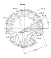
図3は、従来の光電チャンバーPA-10 の断面図を示す。このチャンバーは、内部に感知するボリュームPA-14 を有するハウジングPA-12 を含む。
光の放射源PA-16 がハウジングに設けられ、光のビームPA-18 を内部の光感知領域PA-14 へ放射するように向けられる。図3に示されるように、放射された光ビームPA-18 は、それが領域PA-14を横切るにしたがって、幾らかコニカル状に広がった形状を示す。光ビームPA-18 は、ハウジングPA-12 の方へ向けられ、そこで吸収される。
【0013】
光電センサーPA-20 は、ビームPA-18 の軸から外れている。センサーPA-20 は、ボリュームPA-14 にある粒子状の物質によって散乱される、ビームPA-18 からの光がそこへ入射し、それによって、出力の電気信号を生じる。
素子PA-22 とPA-24 は、センサーPA-20 に入る光の量を制限する。
チャンバーPA-10 の形状に対して煙の粒子が検出される領域である、効果的な感知する光のボリュームは、0.064立方インチのオーダーである。
図4は、本発明による22iのような代表的な煙感知器の煙感知チャンバーの断面図である。ハウジング30は、例えば、3インチあるいはそれ以下のオーダーの直径を有する。例えば、2.5 インチあるいはそれ以下のオーダーのハウジングが用いられる。
【0014】
強度の強いコヒーレント光源30-1、例えば、レーザーあるいはレーザーダイオードは、ハウジング、またはチャンバー30に配置される。光源はパルス化され、それが周期的間隔で短いパルスの光を(数秒ごとに)放射するようにする。
レンズ30-2は、光を小さいが強いビーム30-3にフォーカスする。光ビーム30-3は、それがチャンバーの反対側にある光トラップ30-4に到達するまで、感知器のチャンバーをとおして連続する。光トラップは、ほとんどの光を吸収し、中央のチャンバー領域から離れて僅かな量を反射する。
好ましくは、レンズ30-2と共同しているソース30-1は、0.0022立方インチのオーダーの効果的なビーム、あるいは光感知ボリュームを有するビーム30-3を生成する。このビームのボリュームは、従来の感知器のそれの3パーセントのオーダーである。
【0015】
従って、ごみの粒子はビーム30-3の直径とボリュームに比較して大きい。光ビーム30-3の大きさばかりでなく感知ビームのボリュームの大きさも周囲のごみの粒子間の一般的な距離よりも小さい。
後で述べるように、この減少したボリュームは、感知器30を小さくし、おそらくごみが誘発する出力信号を発生する。
前に、適した早期に警報を出す感知器を説明した。図5に示されているように、このような煙感知器は、散乱した放射エネルギー30-8のコレクタあるいはバッフルも有する。
上述のように、散乱した光粒子がセンサー30-7に到達することができる光ビームのボリュームは、センサーのボリュームと比較して小さい。この小さなボリュームは、効果的な散乱ボリューム(Effective Scattering Volume: ESV)と呼ばれる。
【0016】
比較的大きく、まばらである埃や繊維状の粒子と比較して、煙の粒子は、小さく、数が多い。ESVは、その大きさは空気で運ばれる大きな埃の粒子間の一般的な距離と比べて小さいが、実際の火災における煙の粒子間距離と比べて大きいように、設計される。このように、2つ以上の大きな埃の粒子 (センサー30-7において重要な信号を与えるのに十分大きい) が同時にESVを占有することは、まったく起こりそうもない。空気で運ばれる粒子は、一定の移動をするので、たまの埃粒子は、埃粒子がESVの内外を通るにしたがって、センサー30-7において過渡信号を生じる。煙の粒子は、多くがESV中にあるので、センサーにおいて比較的一定の信号を発生する。幾らかはESVから出るが、他のものは、内部を移動する。
【0017】
繊維状の粒子は、埃と同様に働く(ESVを通過し、過渡的な信号のみを生じる)。しかし、それらは一つの大きさが非常に長いので、繊維の一端がセンサーの表面に接触し、多端がESVに侵入することが可能である。この状態は図5に示されている。繊維状の粒子Fがそこに図示されている感知器に入る。
繊維Fは空気で運ばれないので、長い時間の間この位置にとどまり、一定の信号をセンサー30-7と制御装置12に与える。繊維状の粒子は、煙の粒子と比較すると、一般には非常に大きいので、それらの粒子は、それらの存在を検知するステップがとられない限り、誤り警報を生じる。
本システムおよび方法は、煙と繊維状の粒子間で区別する。第1の感知器から受信した信号が起こりうる火災を示すのに十分おおきいと、まずソフトウェアを介して制御プロセッサ14は、その感知器に対して記憶装置16に記憶されている前の測定値を分析する。もし、前の記憶された読み取りが火災状態、例えば、時間と共に比較的ゆっくりした増加を示すプロファイルを示すなら、その感知からの信号は、煙を示し、警報が制御装置12によって、また制御装置12において出される。他の火災のプロファイルが用いられることが理解されるであろう。例えば、第1の感知器からの出力信号の傾斜がプリセットされた値と比較されてもよい。代わりに、パターン認識技術が本発明の精神および範囲から逸脱することなく用いられる。
【0018】
もし、その感知器から受信した信号が、非常に低いレベルから数秒で警報レベルまで比較的急な増加を示すなら、これは、おそらく繊維であり、警報表示は更なる分析のために、遅延される。もし、その感知器から受信した信号が、上述のように、繊維を表示するように決められるなら、制御装置12は、同じ部屋か同じ物理的空間に配置されていることが知られている第2の感知器から受信した信号を分析する。例えば、もし、図1において、起こりうる繊維や煙の警報指示が感知器22-kから受信するなら、制御装置12は、感知器22-l' や22-k' でなく、感知器22-lからの出力を調べる。もし、重要でない信号、更に非常に低い信号が所定の時間の間に(同じ部屋R1にある)感知器22-1から受信すると、これは、感知器22-kの信号が煙りでなく、繊維状の粒子によって発生されることの証拠である。もし、第2の感知器22-1の信号のこの欠如がおきると、制御装置12は、警報を示さず、代わりに誤り状態が感知器22-kに存在し、感知器がチェックされ、クリーニングされなければならないことをそのディスプレイ15a上に表示する。もし、代わりに所定の時間の間、小さなアナログ信号が第2の感知器22-1から送られるなら、制御装置12は、第1の感知器22-kのための警報状態を示すであろう。
【0019】
領域R1にある他の感知器22-2、22-3からの出力が同じプロセスにおいて分析されることもできる。好適な分析時間は5秒から60秒の範囲にある。
上述から、いろいろな変形や変更が本発明の精神および範囲から逸脱することなく行われることが理解されるであろう。ここに示された特定の装置に限定されることを意図しなし、考えるべきでないことが解るであろう。勿論、特許請求の範囲に入るすべての変更によってカバーされることが意図されている。
【図面の簡単な説明】
【図1】警報システムのブロック図である。
【図2】図1の警報システムに用いることができる感知器のブロック図である。
【図3】従来の光電感知器の断面図である。
【図4】光電感知器の断面図である。
【図5】繊維状素子を含む感知器の概略図である。[0001]
BACKGROUND OF THE INVENTION
The present invention relates to error detection of electrical signals received from ambient condition sensors, and in particular, the present invention relates to a processing device that minimizes error alarms due to non-smoke changes in electrical signals indicative of ambient conditions such as smoke and fire. And methods.
[0002]
[Prior art]
A variety of systems for the detection of alarm conditions are known. One particular form of such a system is a smoke or fire detection system of the type shown in U.S. Pat. No. 4,916,423 issued to Tice et al. It is captured.
Upon receiving input from one or more of the detectors of the system, a controller associated with the system can make a determination as to whether a fire condition exists in one or more areas of interest. Various techniques have been used in the past for the purpose of making this determination.
Smoke sensors, such as photoelectric smoke detectors and ionization smoke detectors, are intended to provide an output indicative of the detected level of ambient smoke. Ambient noise, such as dust particles and insects that can enter each sensor, causes a change in the output signal from the sensor that is unrelated to the presence of smoke. These noise outputs generate false alarms if the sensitivity of each sensor is very high. Such false alarms are undesirable.
[0003]
In general, a photoelectric smoke sensor used for giving an initial warning uses a light source and a light-sensitive receiver. The design and arrangement of the light source, receiver, and buffing is usually such that no significant light from the light source reaches the receiver unless smoke or other particles are present in the area of the light beam. If smoke or other particles are present in this region, they scatter light photons, allowing some light to reach the receiver.
In smoke-sensing systems that do not warn early, the smoke concentration required for the sensor to generate an alarm is quite large compared to the concentrations of dust, fibers and other non-smoke particles that are normally present, and therefore These systems are not sensitive to the signs of errors caused by these particles. In early warning smoke sensing systems, the signal obtained by low smoke levels may be comparable to the signal obtained by non-smoke particles carried in air in an environment where this type of system is commonly used. .
[0004]
In conventional early warning systems, filters were used to remove non-smoke particles in the air present in the smoke sensor. In general, the presence of a filter requires that the sensor have a fan or other means to exhaust air through the filter. Mechanical fans and filters used in conventional sensors are expensive and require regular maintenance.
[0005]
[Problems to be solved by the invention]
There is a need for a sensor that can be used in early warning systems that do not require fans or filters. It is preferred that minimizing the signs of errors while avoiding the need to incorporate additional mechanical elements is achieved without significantly increasing the cost of such a system.
[0006]
[Means for Solving the Problems]
The fire detector and alarm system according to the invention has a control device and a number of early alarm smoke sensors. Each of these smoke sensors measures the density of smoke particles in that area. Each sensor sends a signal to the controller that is an electrical indication of smoke concentration. The controller processes signals from at least some sensors to determine whether an alarm condition is present.
Since indications of errors caused by particles carried by non-smoke air must be rejected, the system is designed to detect very low levels of smoke.
The ability to discriminate between smoke and fibrous particles, such as flakes, string or human hair, is a significant advantage of the system other than embodying the present invention. A smoke sensor design combined with signal processing software in the controller allows the system to detect these fibrous particles. This design feature minimizes false alarms caused by the presence of such fibers in the system.
[0007]
The system requires that at least two smoke sensors be installed in each room or enclosed space. Large enough fibrous particles that produce false readings are critical, although unlikely to enter a single smoke sensor. The possibility that such particles enter the two sensors at the same time is so small that it is not critical.
When the controller identifies a signal from the first sensor that indicates a smoke alarm, it analyzes the signal to determine whether the reading also indicates fibrous particles. If the reading from the first sensor indicates fibrous particles, the controller analyzes the reading from the second sensor that is known to be in the same room.
If a reading from the second sensor, indicating a small level of smoke, is not received during the predetermined time period, the controller may cause the signal at the first sensor to be a fibrous particle, or some other Indication of non-smoke phenomenon. Maintenance and trouble signals can be generated.
[0008]
Many other advantages and features of the present invention will become readily apparent from the following detailed description of the invention and the embodiments thereof, from the claims and from the drawings.
[0009]
DETAILED DESCRIPTION OF THE INVENTION
While the invention is capable of many different forms of embodiments, the disclosure herein is to be considered as an illustration of the principles of the invention and is not intended to limit the invention to the particular embodiments illustrated. For purposes of understanding, specific embodiments of the invention are shown in the drawings and will be described in detail.
FIG. 1 shows a block diagram of a
[0010]
The
Typical types of detectors include ionic or photoelectric smoke detectors. Other types of ambient condition sensors as well as temperature sensors can be used in the system according to the present invention.
In particular, the
[0011]
FIG. 2 is a representative block diagram of a sensor 22 i that can be used with the
Referring to FIG. Via
[0012]
The method according to the invention is carried out in the
FIG. 3 shows a cross-sectional view of a conventional photoelectric chamber PA-10. The chamber includes a housing PA-12 having a volume PA-14 sensed therein.
A light radiation source PA-16 is provided in the housing and is directed to emit a beam of light PA-18 to the interior light sensitive area PA-14. As shown in FIG. 3, the emitted light beam PA-18 exhibits a shape that expands somewhat conically as it crosses the region PA-14. The light beam PA-18 is directed towards the housing PA-12 where it is absorbed.
[0013]
The photoelectric sensor PA-20 is off the axis of the beam PA-18. Sensor PA-20 receives light from beam PA-18, which is scattered by particulate matter in volume PA-14, thereby producing an output electrical signal.
Elements PA-22 and PA-24 limit the amount of light entering sensor PA-20.
The effective sensing light volume, the area where smoke particles are detected for the shape of chamber PA-10, is on the order of 0.064 cubic inches.
FIG. 4 is a cross-sectional view of a smoke sensing chamber of a typical smoke detector such as 22i according to the present invention. The
[0014]
A strong coherent light source 30-1, for example, a laser or laser diode, is disposed in the housing or
Lens 30-2 focuses the light into a small but strong beam 30-3. The light beam 30-3 continues through the sensor chamber until it reaches a light trap 30-4 on the opposite side of the chamber. The light trap absorbs most of the light and reflects a small amount away from the central chamber region.
Preferably, source 30-1 in conjunction with lens 30-2 produces an effective beam on the order of 0.0022 cubic inches, or beam 30-3 having a light sensitive volume. The volume of this beam is on the order of 3 percent that of a conventional sensor.
[0015]
Therefore, the dust particles are large compared to the diameter and volume of the beam 30-3. Not only the size of the light beam 30-3 but also the volume of the sensing beam is smaller than the general distance between surrounding dust particles.
As will be discussed later, this reduced volume makes the
Previously, a sensor that gave a suitable early warning was described. As shown in FIG. 5, such a smoke detector also has a collector or baffle of scattered radiant energy 30-8.
As described above, the volume of the light beam that the scattered light particles can reach the sensor 30-7 is small compared to the volume of the sensor. This small volume is called an Effective Scattering Volume (ESV).
[0016]
Compared to relatively large and sparse dust and fibrous particles, smoke particles are small and numerous. The ESV is designed so that its size is small compared to the typical distance between large dust particles carried by air, but large compared to the distance between smoke particles in a real fire. Thus, it is highly unlikely that two or more large dust particles (large enough to give an important signal at sensor 30-7) will simultaneously occupy the ESV. Since the particles carried by the air move constantly, the occasional dust particles produce a transient signal at the sensor 30-7 as the dust particles pass inside and outside the ESV. Smoke particles produce a relatively constant signal at the sensor because many are in the ESV. Some will leave the ESV, while others will move inside.
[0017]
Fibrous particles behave like dust (pass through the ESV and produce only transient signals). However, they are so long in one size that one end of the fiber can contact the surface of the sensor and the other end can penetrate the ESV. This state is shown in FIG. Fibrous particles F enter the sensor illustrated therein.
Since the fiber F is not carried by air, it stays in this position for a long time and gives a constant signal to the sensor 30-7 and the
The system and method distinguish between smoke and fibrous particles. If the signal received from the first sensor is large enough to indicate a possible fire, first via the software, the
[0018]
If the signal received from the sensor shows a relatively steep increase from a very low level to an alarm level in seconds, this is probably a fiber and the alarm display is delayed for further analysis. The If the signal received from the sensor is determined to display the fiber as described above, the
[0019]
The output from other sensors 22-2, 22-3 in region R1 can also be analyzed in the same process. A suitable analysis time is in the range of 5 to 60 seconds.
From the foregoing, it will be understood that various modifications and changes can be made without departing from the spirit and scope of the invention. It will be understood that it is not intended and should not be considered to be limited to the specific apparatus shown here. Of course, it is intended to be covered by all modifications falling within the scope of the claims.
[Brief description of the drawings]
FIG. 1 is a block diagram of an alarm system.
FIG. 2 is a block diagram of a sensor that can be used in the alarm system of FIG.
FIG. 3 is a cross-sectional view of a conventional photoelectric sensor.
FIG. 4 is a cross-sectional view of a photoelectric sensor.
FIG. 5 is a schematic view of a sensor including a fibrous element.
Claims (9)
前記感知器は、それぞれの感知器の隣接領域において感知された状態を示す信号を送信し、
前記第1と第2の感知器は、共通の領域を有し、且つ、
前記制御装置は:
前記共通の領域において前記第1の感知器から受信した信号が前記第1の感知器に入った、空気によって運ばれる煙でない物質を示すものであるか否かを決定する手段と;
前記共通の領域にある前記第2の感知器が警報状態を示す信号を前記制御装置に送信するか否かを決定する他の手段と;
警報状態の存在を示す手段と、
を有することを特徴とする警報システム。An alarm system comprising: a control device; a communication link connected to the control device; and at least first and second smoke detectors connected to the communication link,
The sensors transmit signals indicative of a sensed state in an adjacent area of each sensor;
The first and second sensors have a common area; and
The control device is:
Means for determining whether a signal received from the first sensor in the common area is indicative of a non-smoke material carried by the air entering the first sensor;
Other means for determining whether said second sensor in said common area sends a signal indicating an alarm condition to said control device;
Means to indicate the presence of an alarm condition;
An alarm system characterized by comprising:
Applications Claiming Priority (2)
| Application Number | Priority Date | Filing Date | Title |
|---|---|---|---|
| US08/853605 | 1997-05-09 | ||
| US08/853,605 US6150935A (en) | 1997-05-09 | 1997-05-09 | Fire alarm system with discrimination between smoke and non-smoke phenomena |
Publications (2)
| Publication Number | Publication Date |
|---|---|
| JPH1166452A JPH1166452A (en) | 1999-03-09 |
| JP3973762B2 true JP3973762B2 (en) | 2007-09-12 |
Family
ID=25316486
Family Applications (1)
| Application Number | Title | Priority Date | Filing Date |
|---|---|---|---|
| JP16578798A Expired - Fee Related JP3973762B2 (en) | 1997-05-09 | 1998-05-11 | Alarm system |
Country Status (4)
| Country | Link |
|---|---|
| US (1) | US6150935A (en) |
| EP (1) | EP0877347B1 (en) |
| JP (1) | JP3973762B2 (en) |
| DE (1) | DE69821671T2 (en) |
Families Citing this family (25)
| Publication number | Priority date | Publication date | Assignee | Title |
|---|---|---|---|---|
| US6879253B1 (en) * | 2000-03-15 | 2005-04-12 | Siemens Building Technologies Ag | Method for the processing of a signal from an alarm and alarms with means for carrying out said method |
| DE10046992C1 (en) * | 2000-09-22 | 2002-06-06 | Bosch Gmbh Robert | Scattered light smoke |
| US7068177B2 (en) * | 2002-09-19 | 2006-06-27 | Honeywell International, Inc. | Multi-sensor device and methods for fire detection |
| CN101680832A (en) * | 2007-03-09 | 2010-03-24 | 爱克斯崔里斯科技有限公司 | Method and system for particle detection |
| US8378808B1 (en) | 2007-04-06 | 2013-02-19 | Torrain Gwaltney | Dual intercom-interfaced smoke/fire detection system and associated method |
| US7847700B2 (en) * | 2007-07-03 | 2010-12-07 | Conforti Fred J | System and method for an optical particle detector |
| EP2053574B1 (en) * | 2007-10-25 | 2014-11-12 | Securiton AG | Smoke detector with particle suppression |
| US8284065B2 (en) * | 2008-10-03 | 2012-10-09 | Universal Security Instruments, Inc. | Dynamic alarm sensitivity adjustment and auto-calibrating smoke detection |
| US8766807B2 (en) * | 2008-10-03 | 2014-07-01 | Universal Security Instruments, Inc. | Dynamic alarm sensitivity adjustment and auto-calibrating smoke detection |
| US8098166B2 (en) | 2009-04-23 | 2012-01-17 | Honeywell International Inc. | Variable air speed aspirating smoke detector |
| US8395501B2 (en) | 2010-11-23 | 2013-03-12 | Universal Security Instruments, Inc. | Dynamic alarm sensitivity adjustment and auto-calibrating smoke detection for reduced resource microprocessors |
| US8681011B2 (en) * | 2011-02-21 | 2014-03-25 | Fred Conforti | Apparatus and method for detecting fires |
| RU2487416C1 (en) * | 2011-10-31 | 2013-07-10 | Сергей Иванович Бурдюгов | Adaptive method of fire alarm |
| US8994562B1 (en) | 2011-12-06 | 2015-03-31 | Shane Daniel | Boat monitoring systems and methods |
| CN102521943A (en) * | 2012-01-10 | 2012-06-27 | 浙江宇安消防装备有限公司 | Portable escape equipment storage box and community intelligent fire-fighting early-warning integrated device |
| US9202359B2 (en) * | 2012-08-30 | 2015-12-01 | Honeywell International Inc. | Multilevel signaling system and method |
| CN104332037B (en) * | 2014-10-27 | 2017-02-15 | 小米科技有限责任公司 | method and device for alarm detection |
| US9934672B2 (en) * | 2015-09-24 | 2018-04-03 | Honeywell International Inc. | Systems and methods of conserving battery life in ambient condition detectors |
| DE102016209052A1 (en) * | 2016-05-24 | 2017-11-30 | Hekatron Vertriebs Gmbh | Procedure for detecting smoke and hazard detectors |
| US10540871B2 (en) | 2017-07-05 | 2020-01-21 | Oneevent Technologies, Inc. | Evacuation system |
| WO2020010599A1 (en) | 2018-07-13 | 2020-01-16 | Carrier Corporation | High sensitivity fiber optic based detection |
| US11176796B2 (en) | 2018-07-13 | 2021-11-16 | Carrier Corporation | High sensitivity fiber optic based detection |
| US11340172B2 (en) | 2018-07-13 | 2022-05-24 | Carrier Corporation | Enhanced robustness for high sensitivity fiber optic smoke detection |
| US11936489B2 (en) | 2021-02-02 | 2024-03-19 | True Manufacturing Co., Inc. | Systems, methods, and appliances that enable regional control of refrigeration appliances |
| WO2022256749A2 (en) | 2021-06-04 | 2022-12-08 | Smart Cellular Labs, Llc | Integrated smoke alarm communications system |
Family Cites Families (7)
| Publication number | Priority date | Publication date | Assignee | Title |
|---|---|---|---|---|
| US4611197A (en) * | 1985-02-19 | 1986-09-09 | Sansky Michael J | Malfunction-detecting status monitoring system |
| US4812819A (en) * | 1987-04-13 | 1989-03-14 | The United States Of America As Represented By The United States Department Of Energy | Functional relationship-based alarm processing system |
| US4916432A (en) * | 1987-10-21 | 1990-04-10 | Pittway Corporation | Smoke and fire detection system communication |
| US5172096A (en) * | 1991-08-07 | 1992-12-15 | Pittway Corporation | Threshold determination apparatus and method |
| US5483222A (en) * | 1993-11-15 | 1996-01-09 | Pittway Corporation | Multiple sensor apparatus and method |
| US5557262A (en) * | 1995-06-07 | 1996-09-17 | Pittway Corporation | Fire alarm system with different types of sensors and dynamic system parameters |
| US5736928A (en) * | 1995-09-01 | 1998-04-07 | Pittway Corporation | Pre-processor apparatus and method |
-
1997
- 1997-05-09 US US08/853,605 patent/US6150935A/en not_active Expired - Lifetime
-
1998
- 1998-05-08 EP EP98303622A patent/EP0877347B1/en not_active Expired - Lifetime
- 1998-05-08 DE DE1998621671 patent/DE69821671T2/en not_active Expired - Lifetime
- 1998-05-11 JP JP16578798A patent/JP3973762B2/en not_active Expired - Fee Related
Also Published As
| Publication number | Publication date |
|---|---|
| EP0877347A2 (en) | 1998-11-11 |
| DE69821671T2 (en) | 2005-01-13 |
| JPH1166452A (en) | 1999-03-09 |
| US6150935A (en) | 2000-11-21 |
| EP0877347A3 (en) | 2000-01-19 |
| DE69821671D1 (en) | 2004-03-25 |
| EP0877347B1 (en) | 2004-02-18 |
Similar Documents
| Publication | Publication Date | Title |
|---|---|---|
| JP3973762B2 (en) | Alarm system | |
| JP3860635B2 (en) | Fire alarm system with smoke particle identification function | |
| US6967582B2 (en) | Detector with ambient photon sensor and other sensors | |
| US7602304B2 (en) | Multi-sensor device and methods for fire detection | |
| US7129847B2 (en) | Detector with dust filter and airflow monitor | |
| EP1057149B1 (en) | Flame and smoke detector | |
| US5552765A (en) | Smoke detector with individually stored range of acceptable sensitivity | |
| US20090051552A1 (en) | Fire or Smoke Detector with High False Alarm Rejection Performance | |
| DE50202632D1 (en) | OUTSIDE FIRE DETECTION DEVICE | |
| US9459208B2 (en) | Duct detector with remote airflow test capability | |
| US7493816B1 (en) | Smoke detectors | |
| US5818326A (en) | Early fire detection using temperature and smoke sensing | |
| EP0762358B1 (en) | Fire detection system | |
| JPS6325398B2 (en) | ||
| JPH01270199A (en) | Early detection of fire and fire alarm for implementing the same | |
| CN110892460B (en) | Chamber-less smoke detector with indoor air quality detection and monitoring | |
| US6195011B1 (en) | Early fire detection using temperature and smoke sensing | |
| JPH07200961A (en) | Fire alarm system for early detection of fire | |
| US7019657B2 (en) | Method, apparatus and system for fire detection | |
| EP4160563A1 (en) | Fire discrimination by temporal pattern analysis | |
| KR20220052004A (en) | Method and apparatus for detecting fire | |
| GB2260812A (en) | Detecting hazardous substances present in an area |
Legal Events
| Date | Code | Title | Description |
|---|---|---|---|
| A621 | Written request for application examination |
Free format text: JAPANESE INTERMEDIATE CODE: A621 Effective date: 20050329 |
|
| A131 | Notification of reasons for refusal |
Free format text: JAPANESE INTERMEDIATE CODE: A131 Effective date: 20061211 |
|
| A524 | Written submission of copy of amendment under article 19 pct |
Free format text: JAPANESE INTERMEDIATE CODE: A524 Effective date: 20070308 |
|
| TRDD | Decision of grant or rejection written | ||
| A01 | Written decision to grant a patent or to grant a registration (utility model) |
Free format text: JAPANESE INTERMEDIATE CODE: A01 Effective date: 20070514 |
|
| A61 | First payment of annual fees (during grant procedure) |
Free format text: JAPANESE INTERMEDIATE CODE: A61 Effective date: 20070613 |
|
| R150 | Certificate of patent or registration of utility model |
Free format text: JAPANESE INTERMEDIATE CODE: R150 |
|
| FPAY | Renewal fee payment (event date is renewal date of database) |
Free format text: PAYMENT UNTIL: 20100622 Year of fee payment: 3 |
|
| LAPS | Cancellation because of no payment of annual fees |