EP0877347A2 - Fire alarm systems - Google Patents
Fire alarm systems Download PDFInfo
- Publication number
- EP0877347A2 EP0877347A2 EP98303622A EP98303622A EP0877347A2 EP 0877347 A2 EP0877347 A2 EP 0877347A2 EP 98303622 A EP98303622 A EP 98303622A EP 98303622 A EP98303622 A EP 98303622A EP 0877347 A2 EP0877347 A2 EP 0877347A2
- Authority
- EP
- European Patent Office
- Prior art keywords
- smoke
- detector
- detectors
- fire
- alarm
- Prior art date
- Legal status (The legal status is an assumption and is not a legal conclusion. Google has not performed a legal analysis and makes no representation as to the accuracy of the status listed.)
- Granted
Links
Images

Classifications
-
- G—PHYSICS
- G08—SIGNALLING
- G08B—SIGNALLING OR CALLING SYSTEMS; ORDER TELEGRAPHS; ALARM SYSTEMS
- G08B17/00—Fire alarms; Alarms responsive to explosion
- G08B17/10—Actuation by presence of smoke or gases, e.g. automatic alarm devices for analysing flowing fluid materials by the use of optical means
- G08B17/103—Actuation by presence of smoke or gases, e.g. automatic alarm devices for analysing flowing fluid materials by the use of optical means using a light emitting and receiving device
- G08B17/107—Actuation by presence of smoke or gases, e.g. automatic alarm devices for analysing flowing fluid materials by the use of optical means using a light emitting and receiving device for detecting light-scattering due to smoke
-
- G—PHYSICS
- G08—SIGNALLING
- G08B—SIGNALLING OR CALLING SYSTEMS; ORDER TELEGRAPHS; ALARM SYSTEMS
- G08B29/00—Checking or monitoring of signalling or alarm systems; Prevention or correction of operating errors, e.g. preventing unauthorised operation
- G08B29/18—Prevention or correction of operating errors
- G08B29/185—Signal analysis techniques for reducing or preventing false alarms or for enhancing the reliability of the system
-
- G—PHYSICS
- G08—SIGNALLING
- G08B—SIGNALLING OR CALLING SYSTEMS; ORDER TELEGRAPHS; ALARM SYSTEMS
- G08B17/00—Fire alarms; Alarms responsive to explosion
- G08B17/10—Actuation by presence of smoke or gases, e.g. automatic alarm devices for analysing flowing fluid materials by the use of optical means
- G08B17/11—Actuation by presence of smoke or gases, e.g. automatic alarm devices for analysing flowing fluid materials by the use of optical means using an ionisation chamber for detecting smoke or gas
- G08B17/113—Constructional details
Definitions
- the present invention relates to fire alarm systems, and in particular to fault detection of electrical signals received from ambient condition sensors. More particularly, the invention relates to processing apparatus and methods for minimizing false alarms due to non-smoke variations in electrical signals indicative of ambient conditions such as smoke or fire.
- a control unit associated with the system Upon receipt of inputs from one or more of the detectors of the system, a control unit associated with the system is able to make a determination as to whether or not a fire condition is present in one or more regions of interest. A variety of techniques have been used in the past for the purpose of making this determination.
- Sensors of smoke such as photoelectric smoke detectors or ionization-type smoke detectors are intended to provide outputs indicative of sensed levels of ambient smoke.
- Environmental noise such as dust particles or insects which may enter the respective detector can produce variations in output signals from the sensors which are not in any way correlated with the presence of smoke. These noise outputs can produce false alarms if the sensitivity of the respective detector is high enough. Such false alarms are undesirable.
- Photoelectric smoke sensors used for early warning typically use a light source and a light sensitive receiver.
- the design and placement of the light source, receiver, and baffling are such that no significant light from the source normally reaches the receiver unless smoke or other particles are present in the area of the light beam. If smoke or other particles are present in this area, they will scatter the light photons, and cause some of the light to reach the receiver.
- non-early warning smoke detection systems the density of smoke required at a sensor to cause an alarm is relatively large compared to the density of dust, fibers and other non-smoke particles normally existing in the environment, therefore these systems are not susceptible to false indications caused by such particles.
- the signals given by low levels of smoke may be comparable to that given by non-smoke airborne particles in the environment that this type of system is typically used.
- filters were used to remove non-smoke particles in the air present in the smoke sensors.
- the presence of a filter usually requires that the sensor include a fan or other means to draw air through the filter.
- the mechanical fans and filters used in prior art detectors are expensive, subject to failure, and require regular maintenance.
- detectors which can be used in early warning systems without requiring the presence of fans or filters. Preferably minimizing false indications could be accomplished without significantly increasing the expense of such systems while avoiding any need to incorporate additional mechanical components.
- a fire detection and alarm system in accordance with the present invention includes a control unit and multiple early warning smoke sensors. Each of these smoke sensors measures the density of smoke particles in its area. Each of the sensors then sends a signal to the control unit which is an electrical indication of that smoke density. The control unit processes the signals from at least some of the sensors and determines if an alarm condition exists.
- the system requires that at least two smoke sensors be installed in each room or enclosed space.
- the probability that a fiber particle, large enough to cause a false reading, will enter a single smoke sensor is small, but significant.
- the probability that such a particle will enter two sensors at the same time is so small as to be insignificant.
- control unit When the control unit identifies a signal from a first sensor that could be indicative of smoke alarm, it then analyzes the signal and determines if the reading could also be indicative of fiber particle. If the reading from the first sensor could be indicative of a fiber particle, the control unit then analyzes a reading from a second detector known to be in the same room.
- control unit will provide an indication that the signal at the first sensor has been caused by a fiber particle or some other non-smoke phenomenon. A maintenance or trouble signal can then be generated.
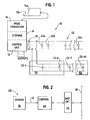
- FIG. 1 illustrates a block diagram of a system 10 in accordance with the present invention.
- This system 10 includes a control unit 12, which can be implemented with a programmable processor 14 and a storage unit 16.
- the storage unit 16 can include both control programs and data storage regions for use by the processor 14.
- the control unit 12 is coupled by a bidirectional communication link 20 to a plurality of ambient condition sensors or detectors generally indicated at 22.
- the members of the plurality 22, such as sensors 22a, 22b--22n are intended to detect a particular ambient condition in an adjacent region.
- the system 12 can also include an operator display unit with an output visual display device 15a and an operator control or input device such as keyboard 15b.
- the control unit 12 also includes a plurality of system outputs.
- the outputs can be used to activate audible or visual alarms.
- the unit 12 can be coupled to ventilation or air handling systems in the building so as to control smoke migration.
- detectors include ionization-type or photoelectric-type smoke detectors. Temperature sensors as well as other types of ambient condition sensors could be used in the system 10 in accordance with the present invention.
- the system 10 is intended to monitor one or more regions, for example regions R1, R2 which might or might not be contiguous.
- regions R1, R2 which might or might not be contiguous.
- detectors 22-1, 22-2 -- 22-k are located in region R1.
- Detectors 22-1' -- 22-k' are located in region R2.
- the regions R1, R2 can be substantially closed rooms for example.
- FIG. 2 is a block diagram representation of a detector 22i useable with the system 10.
- the detector 22i includes a sensor element 30.
- the element 30 is intended to sense a particular ambient condition, such as smoke, temperature, infrared radiation or the like and it generates an electrical system indicative thereof on a line 32.
- output from the sensor 30, on the line 32 is coupled to a local detector control element 40.
- the control element 40 could be implemented with either digital or analog circuitry. If in digital form, the control element 40 could be implemented as either hard wired logic or could incorporate a programmed microprocessor.
- the control element 40, via interface circuitry 42 is capable of carrying on bidirectional communication with the system control unit 12, via the communication link 20.
- a method in accordance with the present invention could be implemented in either the system control unit 12 or the detector local control element 40 without limitation.
- Implementation can be by either hardwired circuitry or by means of a programmed microprocessor also without limitation.
- FIG. 3 illustrates in cross-section, a prior art photoelectric chamber PA-10.
- This chamber includes a housing PA-12 with an internal sensing volume PA-14.
- a light emitting source, PA-16 is carried on the housing and oriented to emit a beam of light PA-18 into the internal light sensing region PA-14. As is illustrated in FIG. 3, the emitted light beam PA-18 exhibits a somewhat conical expanding shape as it traverses the region PA-14. The light beam PA-18 is directed toward and absorbed on the housing PA-12.
- a photoelectric sensor PA-20 Offset from the axis of the beam PA-18 is a photoelectric sensor PA-20.
- the sensor PA-20 is oriented such that light from the beam PA-18 which has been scattered by particulate matter in the volume PA-14 will be incident thereon thereby generating an output electrical signal.
- Elements PA-22 and PA-24 limit the amount of light which can fall upon the sensor PA-20.
- the effective sensing light volume which is the region in which smoke particles can be detected.
- the geometry of the chamber PA-10 is on the order of .064 cubic inches.
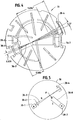
- FIG. 4 is a cross-sectional drawing of a smoke sensing chamber 30 of a representative smoke detection device such as 22i in accordance with the present invention.
- the housing 30 could, for example, have a diameter on the order of three inches or less.
- a housing with a diameter on the order of two and one-half inches or less could be used.
- the light source is pulsed to cause it to emit a short pulse of light at periodic intervals (every few seconds).
- a lens 30-2 focuses the light into a small but intense beam 30-3.
- the light beam 30-3 continues through the detector chamber until it strikes a light trap 30-4 at the opposite end of the chamber.
- the light trap absorbs most of the light, and reflects a small amount away from the central chamber area.
- source 30-1 in combination with the lens 30-2 will produce a beam 30-3 having an effective beam or light sensing volume on the order of .0022 cubic inches.
- This beam volume is on the order of 3% that of prior art detectors.
- dust particles are large compared to the diameter and volume of the beam 30-3.
- the dimensions of light beam 30-3 as well as those of the sensing beam volume are smaller than a typical distance between ambient dust particles. As described subsequently, this reduced volume makes the detector 30 less likely to produce dust induced output signals which appear to be due to the presence of smoke.
- Such smoke detectors can also include a collector or baffle of scattered radiant energy 30-8.
- ESV Effective Scattering Volume
- Smoke particles are small and numerous compared to dust and fiber particles, which are relatively large and sparse.
- the ESV is designed so its dimensions are small relative to the typical distance between large airborne dust particles, yet large relative to the distance between smoke particles in a true fire. In this way is very unlikely that more than one large dust particle (large enough to give a significant signal at the sensor 30-7) will occupy the ESV at the same time. Since the airborne particles are in constant motion, the occasional dust particles will cause a transient signal at the sensor 30-7 as the dust particles pass in and out of the ESV. Smoke particles generate a relatively constant signal at the sensor because many are in the ESV, and as some pass out of the ESV, others move in.
- Fiber particles may perform similarly to dust (i.e. pass through the ESV and cause only a transient signal). However, since they are very long in one dimension, it is possible that one end of the fiber may touch a surface in the sensor and the other end encroach on the ESV. This situation is illustrated in FIG. 5. Fiber particle F has entered the detector illustrated therein.
- the fiber F Since the fiber F is not airborne, it may remain in this position for a long period of time and provide a constant signal to the sensor 30-7 and control unit 12. Since fiber particles are typically very large compared to smoke particles, their presence can cause a false alarm unless steps are taken to detect their presence.
- the present system and method discriminate between smoke and fiber particles.
- the control processor 14 via software first analyzes previous measurements stored in memory 16 for that detector. If the previous stored readings exhibit a profile indicative of a fire condition, such as a relatively gradual increase over time, the signal from that detector is indicative of smoke and an alarm is indicated by and at the control unit 12. It will be understood that other fire profiles can be used. For example, the slopes of the output signals from the first detector can be compared to a preset value. Alternately, pattern recognition techniques could be used without departing from the spirit and scope of the present invention.
- the control unit 12 analyzes the signals received from a second detector known to be located in the same room or physical space.
- the control unit 12 will examine the output from detector 22-1, not detectors 22-1' or 22-k'. If no significant signal, even a very low signal, is received from detector 22-1, (which is in the same room R1), for a predetermined time period, this is further evidence that the signal at the detector 22-k is caused by a fiber particle and not smoke. If this lack of signal at the second detector 22-1 occurs, the control unit 12 does not indicate an alarm but instead indicates on its display 15a that a fault condition exists in the detector 22-k and that detector must be checked or cleaned. If instead, during the predetermined time period, a small analog signal is being sent from the second detector 22-1, the control unit 12 will indicate an alarm condition for the first detector 22-k.
- a preferred analysis time is in a range of 5 to 60 seconds.
Abstract
Description
Claims (20)
- An alarm system comprising:a control unit;a communications link coupled to the control unit;a plurality of spaced-apart ambient condition detectors coupled to the communications link, each such detector being operable to transmit a signal indicative of ambient conditions sensed in regions adjacent to the detector concerned; andcircuitry for indicating the presence of an alarm condition, the control unit including circuitry for determining if a signal received from a selected detector in a predetermined region is indicative of the possible presence of a foreign element in the detector and additional circuitry for determining whether a second detector in the same region is transmitting signals to the control unit indicative of possible alarm condition.
- A system as claimed in claim 1 wherein at least some of the detectors sense ambient smoke.
- A system as claimed in claim 1 or 2 wherein the control unit includes circuitry for storage of prior signal values from the selected detector.
- A system as claimed in claim 3 wherein the determining circuitry analyzes the stored prior values for the detector and in response to a trend indicating a fire condition, enables the circuitry for indicating the alarm condition.
- A system as claimed in claim 4 which includes delay circuitry in the event that the trend does not indicate a fire condition.
- A fire alarm system as claimed in claim 1 wherein said plurality of detectors comprises multiple smoke sensors which are monitored by a control panel of said control unit, and said smoke sensors send signals to said control panel that indicate the level of smoke sensed by said smoke sensors, and said control panel uses said signals from at least two of said smoke sensors in order to reach a decision that a fire condition exists and to distinguish a fire condition from a non-fire condition.
- A fire alarm system as claimed in claim 1 wherein said plurality of detectors comprises multiple smoke sensors which are monitored by a control panel of said control unit, and said smoke sensors output signals to said control panel that indicate the level of smoke sensed by said smoke sensors, and said control panel uses said signals from at least two of the said smoke sensors in order to reach a decision that non-smoke airborne material has intruded into one of said sensors.
- A fire alarm system as claimed in claim 1 wherein said plurality of detectors comprises multiple smoke sensors which are monitored by a control panel of said control unit, and said smoke sensors send signals to said control panel that indicate the level of smoke sensed by said smoke sensors, and said control panel uses said signal received from a first smoke sensor to determine if a possible alarm condition exists, and if the signal from said first sensor has a sharp increase with respect to time, said control panel performs further processing of the signals from a second sensor before making a decision that a fire alarm condition exists at said first sensor or making a decision that a special non-fire condition exists at said first sensor.
- A system as claimed in claim 8 where said control panel indicates that a fire alarm condition exists at said first sensor if the signal from said second sensor remains below a predetermined level for a predetermined time.
- A system as claimed in claim 8 where said control panel indicates that a special non-fire condition exists at said first sensor and that maintenance action is necessary if the signal from said second sensor rises above a predetermined level during a predetermined time.
- A method of assessing the presence of an alarm condition in one or more regions being monitored with an alarm system, having a control unit linked to a plurality of detectors, as claimed in claim 1, wherein the alarm condition is the presence of smoke and the detectors are smoke detectors, the method cornprising:establishing at the control unit records of the detectors associated with a plurality of pre-defined, regions being monitored by the alarm system;receiving at the control unit signals from the detectors indicative of a sensed level of smoke at the respective detectors;for at least the signal from a first detector, determining if a possible fire condition may be present in the vicinity of the first detector;responsive to said possible fire condition, determining if the record of the first detector exhibits a predetermined trend during a selected time interval, and, in response to the presence of the predetermined trend, producing a signal indicative of an alarm condition, but in the absence of the predetermined trend, evaluating the signal from another detector, located in the same region as the first detector and in the absence of a predetermined signal from the another detector, indicating a fault condition at the first detector.
- A method as claimed in claim 11 wherein at least some of the regions are substantially enclosed.
- A method as claimed in claim 11 wherein the predetermined trend indicates an increasing level of smoke over a predetermined period of time.
- A method as claimed in claim 11 including:
in the presence of a predetermined signal from another detector, indicating an alarm condition. - A method of determining an alarm condition in response to signals received from a plurality of displaced smoke detectors, using an alarm system as in claim 1, the method comprising:receiving signals from at least two detectors in a selected region being monitored;in response to one of the received signals changing in a way indicative of a possible fire, analyzing the one received signal and then other received signals to differentiate between a fire condition and a non-fire condition.
- A method as claimed in claim 15 which includes storing a history of signals received from at least one of the detectors.
- A method as claimed in claim 16 wherein the stored history is used during the analysing step.
- A method as claimed in claim 17 wherein if the stored history includes a profile which indicates that a fire is probable, then an alarm is indicated.
- A method as claimed in claim 17 wherein if the stored profile does not indicate that a fire is probable, indication of an alarm is delayed.
- A method as claimed in claim 19 in the absence of a fire profile, analyzing the other received signal to determine if it is indicative of a fire condition and if not, indicating that a selected non-alarm fault condition may be present at the one detector.
Applications Claiming Priority (2)
| Application Number | Priority Date | Filing Date | Title |
|---|---|---|---|
| US853605 | 1997-05-09 | ||
| US08/853,605 US6150935A (en) | 1997-05-09 | 1997-05-09 | Fire alarm system with discrimination between smoke and non-smoke phenomena |
Publications (3)
| Publication Number | Publication Date |
|---|---|
| EP0877347A2 true EP0877347A2 (en) | 1998-11-11 |
| EP0877347A3 EP0877347A3 (en) | 2000-01-19 |
| EP0877347B1 EP0877347B1 (en) | 2004-02-18 |
Family
ID=25316486
Family Applications (1)
| Application Number | Title | Priority Date | Filing Date |
|---|---|---|---|
| EP98303622A Expired - Lifetime EP0877347B1 (en) | 1997-05-09 | 1998-05-08 | Fire alarm systems |
Country Status (4)
| Country | Link |
|---|---|
| US (1) | US6150935A (en) |
| EP (1) | EP0877347B1 (en) |
| JP (1) | JP3973762B2 (en) |
| DE (1) | DE69821671T2 (en) |
Cited By (3)
| Publication number | Priority date | Publication date | Assignee | Title |
|---|---|---|---|---|
| WO2009052991A1 (en) * | 2007-10-25 | 2009-04-30 | Securiton Ag | Smoke detector with particle suppression means |
| CN104332037A (en) * | 2014-10-27 | 2015-02-04 | 小米科技有限责任公司 | Method and device for alarm detection |
| WO2017202718A1 (en) * | 2016-05-24 | 2017-11-30 | Hekatron Vertriebs Gmbh | Method and hazard detector for identifying smoke |
Families Citing this family (22)
| Publication number | Priority date | Publication date | Assignee | Title |
|---|---|---|---|---|
| US6879253B1 (en) * | 2000-03-15 | 2005-04-12 | Siemens Building Technologies Ag | Method for the processing of a signal from an alarm and alarms with means for carrying out said method |
| DE10066246A1 (en) * | 2000-09-22 | 2005-10-06 | Robert Bosch Gmbh | Scattered light smoke |
| US7068177B2 (en) * | 2002-09-19 | 2006-06-27 | Honeywell International, Inc. | Multi-sensor device and methods for fire detection |
| CN101680832A (en) * | 2007-03-09 | 2010-03-24 | 爱克斯崔里斯科技有限公司 | Method and system for particle detection |
| US8378808B1 (en) | 2007-04-06 | 2013-02-19 | Torrain Gwaltney | Dual intercom-interfaced smoke/fire detection system and associated method |
| US7847700B2 (en) * | 2007-07-03 | 2010-12-07 | Conforti Fred J | System and method for an optical particle detector |
| US8766807B2 (en) * | 2008-10-03 | 2014-07-01 | Universal Security Instruments, Inc. | Dynamic alarm sensitivity adjustment and auto-calibrating smoke detection |
| US8284065B2 (en) * | 2008-10-03 | 2012-10-09 | Universal Security Instruments, Inc. | Dynamic alarm sensitivity adjustment and auto-calibrating smoke detection |
| US8098166B2 (en) | 2009-04-23 | 2012-01-17 | Honeywell International Inc. | Variable air speed aspirating smoke detector |
| US8395501B2 (en) | 2010-11-23 | 2013-03-12 | Universal Security Instruments, Inc. | Dynamic alarm sensitivity adjustment and auto-calibrating smoke detection for reduced resource microprocessors |
| US8681011B2 (en) * | 2011-02-21 | 2014-03-25 | Fred Conforti | Apparatus and method for detecting fires |
| RU2487416C1 (en) * | 2011-10-31 | 2013-07-10 | Сергей Иванович Бурдюгов | Adaptive method of fire alarm |
| US8994562B1 (en) | 2011-12-06 | 2015-03-31 | Shane Daniel | Boat monitoring systems and methods |
| CN102521943A (en) * | 2012-01-10 | 2012-06-27 | 浙江宇安消防装备有限公司 | Portable escape equipment storage box and community intelligent fire-fighting early-warning integrated device |
| US9202359B2 (en) * | 2012-08-30 | 2015-12-01 | Honeywell International Inc. | Multilevel signaling system and method |
| US9934672B2 (en) * | 2015-09-24 | 2018-04-03 | Honeywell International Inc. | Systems and methods of conserving battery life in ambient condition detectors |
| US10540871B2 (en) * | 2017-07-05 | 2020-01-21 | Oneevent Technologies, Inc. | Evacuation system |
| US11176796B2 (en) | 2018-07-13 | 2021-11-16 | Carrier Corporation | High sensitivity fiber optic based detection |
| EP3821415A2 (en) | 2018-07-13 | 2021-05-19 | Carrier Corporation | Enhanced robustness for high sensitivity fiber optic smoke detection |
| US11948439B2 (en) | 2018-07-13 | 2024-04-02 | Carrier Corporation | High sensitivity fiber optic based detection |
| US11936489B2 (en) | 2021-02-02 | 2024-03-19 | True Manufacturing Co., Inc. | Systems, methods, and appliances that enable regional control of refrigeration appliances |
| US11875664B2 (en) | 2021-06-04 | 2024-01-16 | Smart Cellular Labs, Llc | Integrated smoke alarm communications system |
Citations (4)
| Publication number | Priority date | Publication date | Assignee | Title |
|---|---|---|---|---|
| US5172096A (en) * | 1991-08-07 | 1992-12-15 | Pittway Corporation | Threshold determination apparatus and method |
| US5483222A (en) * | 1993-11-15 | 1996-01-09 | Pittway Corporation | Multiple sensor apparatus and method |
| US5557262A (en) * | 1995-06-07 | 1996-09-17 | Pittway Corporation | Fire alarm system with different types of sensors and dynamic system parameters |
| EP0760464A1 (en) * | 1995-09-01 | 1997-03-05 | Pittway Corporation | Pre-processor apparatus and method |
Family Cites Families (3)
| Publication number | Priority date | Publication date | Assignee | Title |
|---|---|---|---|---|
| US4611197A (en) * | 1985-02-19 | 1986-09-09 | Sansky Michael J | Malfunction-detecting status monitoring system |
| US4812819A (en) * | 1987-04-13 | 1989-03-14 | The United States Of America As Represented By The United States Department Of Energy | Functional relationship-based alarm processing system |
| US4916432A (en) * | 1987-10-21 | 1990-04-10 | Pittway Corporation | Smoke and fire detection system communication |
-
1997
- 1997-05-09 US US08/853,605 patent/US6150935A/en not_active Expired - Lifetime
-
1998
- 1998-05-08 EP EP98303622A patent/EP0877347B1/en not_active Expired - Lifetime
- 1998-05-08 DE DE1998621671 patent/DE69821671T2/en not_active Expired - Lifetime
- 1998-05-11 JP JP16578798A patent/JP3973762B2/en not_active Expired - Fee Related
Patent Citations (4)
| Publication number | Priority date | Publication date | Assignee | Title |
|---|---|---|---|---|
| US5172096A (en) * | 1991-08-07 | 1992-12-15 | Pittway Corporation | Threshold determination apparatus and method |
| US5483222A (en) * | 1993-11-15 | 1996-01-09 | Pittway Corporation | Multiple sensor apparatus and method |
| US5557262A (en) * | 1995-06-07 | 1996-09-17 | Pittway Corporation | Fire alarm system with different types of sensors and dynamic system parameters |
| EP0760464A1 (en) * | 1995-09-01 | 1997-03-05 | Pittway Corporation | Pre-processor apparatus and method |
Cited By (3)
| Publication number | Priority date | Publication date | Assignee | Title |
|---|---|---|---|---|
| WO2009052991A1 (en) * | 2007-10-25 | 2009-04-30 | Securiton Ag | Smoke detector with particle suppression means |
| CN104332037A (en) * | 2014-10-27 | 2015-02-04 | 小米科技有限责任公司 | Method and device for alarm detection |
| WO2017202718A1 (en) * | 2016-05-24 | 2017-11-30 | Hekatron Vertriebs Gmbh | Method and hazard detector for identifying smoke |
Also Published As
| Publication number | Publication date |
|---|---|
| US6150935A (en) | 2000-11-21 |
| DE69821671D1 (en) | 2004-03-25 |
| JPH1166452A (en) | 1999-03-09 |
| DE69821671T2 (en) | 2005-01-13 |
| EP0877347A3 (en) | 2000-01-19 |
| JP3973762B2 (en) | 2007-09-12 |
| EP0877347B1 (en) | 2004-02-18 |
Similar Documents
| Publication | Publication Date | Title |
|---|---|---|
| EP0877347B1 (en) | Fire alarm systems | |
| JP3860635B2 (en) | Fire alarm system with smoke particle identification function | |
| US6967582B2 (en) | Detector with ambient photon sensor and other sensors | |
| EP1057149B1 (en) | Flame and smoke detector | |
| US6788197B1 (en) | Fire alarm | |
| EP2244236B1 (en) | Variable air speed aspirating smoke detector | |
| US7602304B2 (en) | Multi-sensor device and methods for fire detection | |
| EP1889238B1 (en) | Fire or smoke detector with high false alarm rejection performance | |
| US5552765A (en) | Smoke detector with individually stored range of acceptable sensitivity | |
| US20030038877A1 (en) | Imaging fire detector | |
| JP2006511822A (en) | Airborne pathogen detection system and method | |
| US5818326A (en) | Early fire detection using temperature and smoke sensing | |
| DE50202632D1 (en) | OUTSIDE FIRE DETECTION DEVICE | |
| CN110892460B (en) | Chamber-less smoke detector with indoor air quality detection and monitoring | |
| US6195011B1 (en) | Early fire detection using temperature and smoke sensing | |
| JPH07200961A (en) | Fire alarm system for early detection of fire | |
| US11062586B2 (en) | Method of monitoring health of protective cover of detection device | |
| EP4160563A1 (en) | Fire discrimination by temporal pattern analysis | |
| EP3460428A1 (en) | Dual wavelength detector | |
| CN117079406A (en) | Fire alarm method, system, device, electronic equipment and storage medium | |
| JP3024786B2 (en) | Fire detector |
Legal Events
| Date | Code | Title | Description |
|---|---|---|---|
| PUAI | Public reference made under article 153(3) epc to a published international application that has entered the european phase |
Free format text: ORIGINAL CODE: 0009012 |
|
| AK | Designated contracting states |
Kind code of ref document: A2 Designated state(s): CH DE GB LI |
|
| AX | Request for extension of the european patent |
Free format text: AL;LT;LV;MK;RO;SI |
|
| PUAL | Search report despatched |
Free format text: ORIGINAL CODE: 0009013 |
|
| AK | Designated contracting states |
Kind code of ref document: A3 Designated state(s): AT BE CH CY DE DK ES FI FR GB GR IE IT LI LU MC NL PT SE |
|
| AX | Request for extension of the european patent |
Free format text: AL;LT;LV;MK;RO;SI |
|
| 17P | Request for examination filed |
Effective date: 20000710 |
|
| AKX | Designation fees paid |
Free format text: CH DE GB LI |
|
| 17Q | First examination report despatched |
Effective date: 20020612 |
|
| GRAP | Despatch of communication of intention to grant a patent |
Free format text: ORIGINAL CODE: EPIDOSNIGR1 |
|
| GRAS | Grant fee paid |
Free format text: ORIGINAL CODE: EPIDOSNIGR3 |
|
| GRAA | (expected) grant |
Free format text: ORIGINAL CODE: 0009210 |
|
| AK | Designated contracting states |
Kind code of ref document: B1 Designated state(s): CH DE GB LI |
|
| PG25 | Lapsed in a contracting state [announced via postgrant information from national office to epo] |
Ref country code: LI Free format text: LAPSE BECAUSE OF FAILURE TO SUBMIT A TRANSLATION OF THE DESCRIPTION OR TO PAY THE FEE WITHIN THE PRESCRIBED TIME-LIMIT Effective date: 20040218 Ref country code: CH Free format text: LAPSE BECAUSE OF FAILURE TO SUBMIT A TRANSLATION OF THE DESCRIPTION OR TO PAY THE FEE WITHIN THE PRESCRIBED TIME-LIMIT Effective date: 20040218 |
|
| REG | Reference to a national code |
Ref country code: GB Ref legal event code: FG4D |
|
| REG | Reference to a national code |
Ref country code: CH Ref legal event code: EP |
|
| REF | Corresponds to: |
Ref document number: 69821671 Country of ref document: DE Date of ref document: 20040325 Kind code of ref document: P |
|
| REG | Reference to a national code |
Ref country code: CH Ref legal event code: PL |
|
| PLBE | No opposition filed within time limit |
Free format text: ORIGINAL CODE: 0009261 |
|
| STAA | Information on the status of an ep patent application or granted ep patent |
Free format text: STATUS: NO OPPOSITION FILED WITHIN TIME LIMIT |
|
| 26N | No opposition filed |
Effective date: 20041119 |
|
| PGFP | Annual fee paid to national office [announced via postgrant information from national office to epo] |
Ref country code: DE Payment date: 20120531 Year of fee payment: 15 |
|
| PGFP | Annual fee paid to national office [announced via postgrant information from national office to epo] |
Ref country code: GB Payment date: 20120426 Year of fee payment: 15 |
|
| GBPC | Gb: european patent ceased through non-payment of renewal fee |
Effective date: 20130508 |
|
| PG25 | Lapsed in a contracting state [announced via postgrant information from national office to epo] |
Ref country code: DE Free format text: LAPSE BECAUSE OF NON-PAYMENT OF DUE FEES Effective date: 20131203 |
|
| REG | Reference to a national code |
Ref country code: DE Ref legal event code: R119 Ref document number: 69821671 Country of ref document: DE Effective date: 20131203 |
|
| PG25 | Lapsed in a contracting state [announced via postgrant information from national office to epo] |
Ref country code: GB Free format text: LAPSE BECAUSE OF NON-PAYMENT OF DUE FEES Effective date: 20130508 |