JP3972012B2 - Sample dispensing mechanism and automatic analyzer equipped with the same - Google Patents
Sample dispensing mechanism and automatic analyzer equipped with the same Download PDFInfo
- Publication number
- JP3972012B2 JP3972012B2 JP2003074751A JP2003074751A JP3972012B2 JP 3972012 B2 JP3972012 B2 JP 3972012B2 JP 2003074751 A JP2003074751 A JP 2003074751A JP 2003074751 A JP2003074751 A JP 2003074751A JP 3972012 B2 JP3972012 B2 JP 3972012B2
- Authority
- JP
- Japan
- Prior art keywords
- sample
- container
- probe
- dispensing
- automatic analyzer
- Prior art date
- Legal status (The legal status is an assumption and is not a legal conclusion. Google has not performed a legal analysis and makes no representation as to the accuracy of the status listed.)
- Expired - Lifetime
Links
Images


Classifications
-
- G—PHYSICS
- G01—MEASURING; TESTING
- G01N—INVESTIGATING OR ANALYSING MATERIALS BY DETERMINING THEIR CHEMICAL OR PHYSICAL PROPERTIES
- G01N35/00—Automatic analysis not limited to methods or materials provided for in any single one of groups G01N1/00 - G01N33/00; Handling materials therefor
- G01N35/10—Devices for transferring samples or any liquids to, in, or from, the analysis apparatus, e.g. suction devices, injection devices
- G01N35/1095—Devices for transferring samples or any liquids to, in, or from, the analysis apparatus, e.g. suction devices, injection devices for supplying the samples to flow-through analysers
-
- G—PHYSICS
- G01—MEASURING; TESTING
- G01N—INVESTIGATING OR ANALYSING MATERIALS BY DETERMINING THEIR CHEMICAL OR PHYSICAL PROPERTIES
- G01N35/00—Automatic analysis not limited to methods or materials provided for in any single one of groups G01N1/00 - G01N33/00; Handling materials therefor
- G01N35/00584—Control arrangements for automatic analysers
- G01N35/0092—Scheduling
-
- B—PERFORMING OPERATIONS; TRANSPORTING
- B01—PHYSICAL OR CHEMICAL PROCESSES OR APPARATUS IN GENERAL
- B01F—MIXING, e.g. DISSOLVING, EMULSIFYING OR DISPERSING
- B01F31/00—Mixers with shaking, oscillating, or vibrating mechanisms
- B01F31/44—Mixers with shaking, oscillating, or vibrating mechanisms with stirrers performing an oscillatory, vibratory or shaking movement
-
- G—PHYSICS
- G01—MEASURING; TESTING
- G01N—INVESTIGATING OR ANALYSING MATERIALS BY DETERMINING THEIR CHEMICAL OR PHYSICAL PROPERTIES
- G01N35/00—Automatic analysis not limited to methods or materials provided for in any single one of groups G01N1/00 - G01N33/00; Handling materials therefor
- G01N35/02—Automatic analysis not limited to methods or materials provided for in any single one of groups G01N1/00 - G01N33/00; Handling materials therefor using a plurality of sample containers moved by a conveyor system past one or more treatment or analysis stations
- G01N35/021—Automatic analysis not limited to methods or materials provided for in any single one of groups G01N1/00 - G01N33/00; Handling materials therefor using a plurality of sample containers moved by a conveyor system past one or more treatment or analysis stations having a flexible chain, e.g. "cartridge belt", conveyor for reaction cells or cuvettes
-
- G—PHYSICS
- G01—MEASURING; TESTING
- G01N—INVESTIGATING OR ANALYSING MATERIALS BY DETERMINING THEIR CHEMICAL OR PHYSICAL PROPERTIES
- G01N35/00—Automatic analysis not limited to methods or materials provided for in any single one of groups G01N1/00 - G01N33/00; Handling materials therefor
- G01N35/02—Automatic analysis not limited to methods or materials provided for in any single one of groups G01N1/00 - G01N33/00; Handling materials therefor using a plurality of sample containers moved by a conveyor system past one or more treatment or analysis stations
- G01N35/025—Automatic analysis not limited to methods or materials provided for in any single one of groups G01N1/00 - G01N33/00; Handling materials therefor using a plurality of sample containers moved by a conveyor system past one or more treatment or analysis stations having a carousel or turntable for reaction cells or cuvettes
-
- G—PHYSICS
- G01—MEASURING; TESTING
- G01N—INVESTIGATING OR ANALYSING MATERIALS BY DETERMINING THEIR CHEMICAL OR PHYSICAL PROPERTIES
- G01N35/00—Automatic analysis not limited to methods or materials provided for in any single one of groups G01N1/00 - G01N33/00; Handling materials therefor
- G01N35/10—Devices for transferring samples or any liquids to, in, or from, the analysis apparatus, e.g. suction devices, injection devices
- G01N35/1002—Reagent dispensers
-
- G—PHYSICS
- G01—MEASURING; TESTING
- G01N—INVESTIGATING OR ANALYSING MATERIALS BY DETERMINING THEIR CHEMICAL OR PHYSICAL PROPERTIES
- G01N35/00—Automatic analysis not limited to methods or materials provided for in any single one of groups G01N1/00 - G01N33/00; Handling materials therefor
- G01N35/10—Devices for transferring samples or any liquids to, in, or from, the analysis apparatus, e.g. suction devices, injection devices
- G01N35/1004—Cleaning sample transfer devices
-
- G—PHYSICS
- G01—MEASURING; TESTING
- G01N—INVESTIGATING OR ANALYSING MATERIALS BY DETERMINING THEIR CHEMICAL OR PHYSICAL PROPERTIES
- G01N35/00—Automatic analysis not limited to methods or materials provided for in any single one of groups G01N1/00 - G01N33/00; Handling materials therefor
- G01N35/10—Devices for transferring samples or any liquids to, in, or from, the analysis apparatus, e.g. suction devices, injection devices
- G01N35/1009—Characterised by arrangements for controlling the aspiration or dispense of liquids
- G01N35/1011—Control of the position or alignment of the transfer device
-
- G—PHYSICS
- G01—MEASURING; TESTING
- G01N—INVESTIGATING OR ANALYSING MATERIALS BY DETERMINING THEIR CHEMICAL OR PHYSICAL PROPERTIES
- G01N35/00—Automatic analysis not limited to methods or materials provided for in any single one of groups G01N1/00 - G01N33/00; Handling materials therefor
- G01N35/10—Devices for transferring samples or any liquids to, in, or from, the analysis apparatus, e.g. suction devices, injection devices
- G01N35/1009—Characterised by arrangements for controlling the aspiration or dispense of liquids
- G01N35/1016—Control of the volume dispensed or introduced
-
- G—PHYSICS
- G01—MEASURING; TESTING
- G01N—INVESTIGATING OR ANALYSING MATERIALS BY DETERMINING THEIR CHEMICAL OR PHYSICAL PROPERTIES
- G01N35/00—Automatic analysis not limited to methods or materials provided for in any single one of groups G01N1/00 - G01N33/00; Handling materials therefor
- G01N35/10—Devices for transferring samples or any liquids to, in, or from, the analysis apparatus, e.g. suction devices, injection devices
- G01N35/1065—Multiple transfer devices
-
- G—PHYSICS
- G01—MEASURING; TESTING
- G01N—INVESTIGATING OR ANALYSING MATERIALS BY DETERMINING THEIR CHEMICAL OR PHYSICAL PROPERTIES
- G01N35/00—Automatic analysis not limited to methods or materials provided for in any single one of groups G01N1/00 - G01N33/00; Handling materials therefor
- G01N35/10—Devices for transferring samples or any liquids to, in, or from, the analysis apparatus, e.g. suction devices, injection devices
- G01N35/1081—Devices for transferring samples or any liquids to, in, or from, the analysis apparatus, e.g. suction devices, injection devices characterised by the means for relatively moving the transfer device and the containers in an horizontal plane
- G01N35/109—Devices for transferring samples or any liquids to, in, or from, the analysis apparatus, e.g. suction devices, injection devices characterised by the means for relatively moving the transfer device and the containers in an horizontal plane with two horizontal degrees of freedom
-
- G—PHYSICS
- G01—MEASURING; TESTING
- G01N—INVESTIGATING OR ANALYSING MATERIALS BY DETERMINING THEIR CHEMICAL OR PHYSICAL PROPERTIES
- G01N35/00—Automatic analysis not limited to methods or materials provided for in any single one of groups G01N1/00 - G01N33/00; Handling materials therefor
- G01N2035/00178—Special arrangements of analysers
- G01N2035/00237—Handling microquantities of analyte, e.g. microvalves, capillary networks
-
- G—PHYSICS
- G01—MEASURING; TESTING
- G01N—INVESTIGATING OR ANALYSING MATERIALS BY DETERMINING THEIR CHEMICAL OR PHYSICAL PROPERTIES
- G01N35/00—Automatic analysis not limited to methods or materials provided for in any single one of groups G01N1/00 - G01N33/00; Handling materials therefor
- G01N35/02—Automatic analysis not limited to methods or materials provided for in any single one of groups G01N1/00 - G01N33/00; Handling materials therefor using a plurality of sample containers moved by a conveyor system past one or more treatment or analysis stations
- G01N35/04—Details of the conveyor system
- G01N2035/0401—Sample carriers, cuvettes or reaction vessels
- G01N2035/0406—Individual bottles or tubes
-
- G—PHYSICS
- G01—MEASURING; TESTING
- G01N—INVESTIGATING OR ANALYSING MATERIALS BY DETERMINING THEIR CHEMICAL OR PHYSICAL PROPERTIES
- G01N35/00—Automatic analysis not limited to methods or materials provided for in any single one of groups G01N1/00 - G01N33/00; Handling materials therefor
- G01N35/10—Devices for transferring samples or any liquids to, in, or from, the analysis apparatus, e.g. suction devices, injection devices
- G01N35/1009—Characterised by arrangements for controlling the aspiration or dispense of liquids
- G01N35/1016—Control of the volume dispensed or introduced
- G01N2035/1018—Detecting inhomogeneities, e.g. foam, bubbles, clots
-
- G—PHYSICS
- G01—MEASURING; TESTING
- G01N—INVESTIGATING OR ANALYSING MATERIALS BY DETERMINING THEIR CHEMICAL OR PHYSICAL PROPERTIES
- G01N35/00—Automatic analysis not limited to methods or materials provided for in any single one of groups G01N1/00 - G01N33/00; Handling materials therefor
- G01N35/10—Devices for transferring samples or any liquids to, in, or from, the analysis apparatus, e.g. suction devices, injection devices
- G01N35/1009—Characterised by arrangements for controlling the aspiration or dispense of liquids
- G01N2035/1025—Fluid level sensing
-
- G—PHYSICS
- G01—MEASURING; TESTING
- G01N—INVESTIGATING OR ANALYSING MATERIALS BY DETERMINING THEIR CHEMICAL OR PHYSICAL PROPERTIES
- G01N35/00—Automatic analysis not limited to methods or materials provided for in any single one of groups G01N1/00 - G01N33/00; Handling materials therefor
- G01N35/10—Devices for transferring samples or any liquids to, in, or from, the analysis apparatus, e.g. suction devices, injection devices
- G01N35/1065—Multiple transfer devices
- G01N2035/1076—Multiple transfer devices plurality or independently movable heads
-
- G—PHYSICS
- G01—MEASURING; TESTING
- G01N—INVESTIGATING OR ANALYSING MATERIALS BY DETERMINING THEIR CHEMICAL OR PHYSICAL PROPERTIES
- G01N35/00—Automatic analysis not limited to methods or materials provided for in any single one of groups G01N1/00 - G01N33/00; Handling materials therefor
- G01N35/10—Devices for transferring samples or any liquids to, in, or from, the analysis apparatus, e.g. suction devices, injection devices
- G01N35/1081—Devices for transferring samples or any liquids to, in, or from, the analysis apparatus, e.g. suction devices, injection devices characterised by the means for relatively moving the transfer device and the containers in an horizontal plane
- G01N35/1083—Devices for transferring samples or any liquids to, in, or from, the analysis apparatus, e.g. suction devices, injection devices characterised by the means for relatively moving the transfer device and the containers in an horizontal plane with one horizontal degree of freedom
- G01N2035/1086—Cylindrical, e.g. variable angle
-
- G—PHYSICS
- G01—MEASURING; TESTING
- G01N—INVESTIGATING OR ANALYSING MATERIALS BY DETERMINING THEIR CHEMICAL OR PHYSICAL PROPERTIES
- G01N35/00—Automatic analysis not limited to methods or materials provided for in any single one of groups G01N1/00 - G01N33/00; Handling materials therefor
- G01N35/10—Devices for transferring samples or any liquids to, in, or from, the analysis apparatus, e.g. suction devices, injection devices
- G01N35/1009—Characterised by arrangements for controlling the aspiration or dispense of liquids
-
- Y—GENERAL TAGGING OF NEW TECHNOLOGICAL DEVELOPMENTS; GENERAL TAGGING OF CROSS-SECTIONAL TECHNOLOGIES SPANNING OVER SEVERAL SECTIONS OF THE IPC; TECHNICAL SUBJECTS COVERED BY FORMER USPC CROSS-REFERENCE ART COLLECTIONS [XRACs] AND DIGESTS
- Y10—TECHNICAL SUBJECTS COVERED BY FORMER USPC
- Y10T—TECHNICAL SUBJECTS COVERED BY FORMER US CLASSIFICATION
- Y10T436/00—Chemistry: analytical and immunological testing
- Y10T436/11—Automated chemical analysis
- Y10T436/111666—Utilizing a centrifuge or compartmented rotor
-
- Y—GENERAL TAGGING OF NEW TECHNOLOGICAL DEVELOPMENTS; GENERAL TAGGING OF CROSS-SECTIONAL TECHNOLOGIES SPANNING OVER SEVERAL SECTIONS OF THE IPC; TECHNICAL SUBJECTS COVERED BY FORMER USPC CROSS-REFERENCE ART COLLECTIONS [XRACs] AND DIGESTS
- Y10—TECHNICAL SUBJECTS COVERED BY FORMER USPC
- Y10T—TECHNICAL SUBJECTS COVERED BY FORMER US CLASSIFICATION
- Y10T436/00—Chemistry: analytical and immunological testing
- Y10T436/11—Automated chemical analysis
- Y10T436/113332—Automated chemical analysis with conveyance of sample along a test line in a container or rack
- Y10T436/114998—Automated chemical analysis with conveyance of sample along a test line in a container or rack with treatment or replacement of aspirator element [e.g., cleaning, etc.]
-
- Y—GENERAL TAGGING OF NEW TECHNOLOGICAL DEVELOPMENTS; GENERAL TAGGING OF CROSS-SECTIONAL TECHNOLOGIES SPANNING OVER SEVERAL SECTIONS OF THE IPC; TECHNICAL SUBJECTS COVERED BY FORMER USPC CROSS-REFERENCE ART COLLECTIONS [XRACs] AND DIGESTS
- Y10—TECHNICAL SUBJECTS COVERED BY FORMER USPC
- Y10T—TECHNICAL SUBJECTS COVERED BY FORMER US CLASSIFICATION
- Y10T436/00—Chemistry: analytical and immunological testing
- Y10T436/25—Chemistry: analytical and immunological testing including sample preparation
- Y10T436/2575—Volumetric liquid transfer
Landscapes
- Chemical & Material Sciences (AREA)
- Physics & Mathematics (AREA)
- Health & Medical Sciences (AREA)
- Life Sciences & Earth Sciences (AREA)
- Analytical Chemistry (AREA)
- Biochemistry (AREA)
- General Health & Medical Sciences (AREA)
- General Physics & Mathematics (AREA)
- Immunology (AREA)
- Pathology (AREA)
- Chemical Kinetics & Catalysis (AREA)
- Automatic Analysis And Handling Materials Therefor (AREA)
Description
【0001】
【発明の属する技術分野】
本発明は試料を試薬と混合することにより試料中の特定成分の定性・定量分析を行うための分析装置の試料分注機構及び自動分析装置に係り、特に時間あたりの分注処理能力の高い試料分注機構及びそれを備えた自動分析装置に関する。
【0002】
【従来の技術】
血液,尿等の生体試料中の特定成分分析に用いられる医用自動分析装置を例にとり説明すると、このような自動分析装置は、患者数の多い大病院,中小病院,医院から検査を請け負い検査を行う検査センターなどにおいて効率良く分析を行うのになくてはならない装置になっている。
【0003】
このような自動分析装置は、コンパクトでより多種類の分析ができ、かつ処理速度の高いものが望まれており、従来種々のものが提案されている。
【0004】
処理速度を高める一つの手段としては、試料分注速度の向上が挙げられる。2つのサンプリングノズルを設け、各サンプリングノズルは異なったタイミングで1つのサンプル容器から2つの反応容器にサンプリング可能な試料分注機構を備えた自動化学分析装置が特許文献1に開示されている。
【0005】
また、一つのサンプリングアームに複数のサンプリングノズルを設け、夫々のノズルは独立した吐出制御が可能な試料分注装置が特許文献2に記載されている。
【0006】
【特許文献1】
特開平3−140869号公報
【特許文献2】
特開2001−66316号公報
【0007】
【発明が解決しようとする課題】
特許文献1に記載の方法はそれぞれの分注プローブが異なったタイミングで分注動作可能なことから600テスト/時間と同等の動作で1200テスト/時間に対処させることができるとしている。しかし、実施例の記載に基づけば、2つの分注プローブは1つのプローブ軸で支持されており、2つの分注プローブは全く独立して試料の分注動作はできないものと考えられる。すなわち、構造上2つの分注プローブを同一のプローブ回転平面上に配置することができないと考えられるので、2つの分注プローブの分注動作を同期させる必要があると考えられる。
【0008】
また、特許文献2に記載の方法は2つの分注プローブが同一の分注アームに設けられているので、同様に異なったタイミングで分注動作ができないものと思われる。
【0009】
本発明の目的は、複数の分注プローブを各々独立して分注動作が可能な試料分注プローブを備え分注速度の向上、フレキシブルな分注動作タイミングを可能にした、試料分注プローブ及びそれを備えた自動分析装置を提供することにある。
【0010】
本発明の試料分注プローブは医用自動分析装置に好適であるが、これに限らず、無機/有機試料の分析装置等にも適用できることは言うまでもない。
【0011】
【課題を解決するための手段】
本発明の課題解決手段は次の通りである。
【0012】
分析対象試料を収容する複数の試料容器を載置可能で、かつ該複数の試料容器の配置を変更可能な機構を備えた試料容器搭載機構と、分析対象試料と試薬を混合する反応容器を複数載置可能で、かつ該複数の反応容器の配置を変更可能な機構を備えた反応容器搭載機構と、試料を前記試料容器から分取し、前記反応容器へ吐出するための試料分注機構と、を備えた試料分注装置において、
前記試料分注装置は、試料の分取,吐出のためのノズルを複数備え、かつ該ノズルは各々独立して試料の分取,吐出のためのノズルの上下動作が可能であり、かつ該ノズルは各々独立して前記試料容器と前記反応容器の間で移動可能な機構を備えたことを特徴とする試料分注装置。
【0013】
試料容器搭載機構は試料容器の位置を移動させることができるものであれば、どのような形態のものでも良い。例えば、複数の試料容器を周上に配置するサンプルディスクを備えた物でも良い。この場合、サンプルディスクと表現しているが必ずしも円板状である必要はない。そのため「ディスクの周上」という表現を用いているが、円板状のディスクの場合は円周上と読み替えることができる。
【0014】
また、試料容器を1つまたは複数搭載できるラックを用い、このラックを移動させる形態のものであっても良い。
【0015】
反応容器搭載機構も同様である。反応ディスクのような形態であっても良いし、反応容器が直線的に移動できるようなものであっても良い。
【0016】
【発明の実施の形態】
本発明の各試料分注機構は試料を採取し、前記反応容器に試料を吐出する動作を繰り返す。複数のノズルを有することにより一つの試料分注機構が試料採取後に反応ディスクへ試料を吐出している最中にその他のノズルが試料の採取を行うことにより試料採取の待機時間を埋めることが可能となり、高速処理を実現することが可能となる。
【0017】
複数の試料分注機構が独立に分注動作可能であることにより頻繁に試料容器からの採取動作が可能となるが、これに伴い試料容器の採取位置への移動時間が短くなるため試料容器を所定の場所へ移動する時間がなくなり、ひいては処理能力を落とす要因となるが、各試料分注機構が複数の試料採取位置から採取可能とすることにより処理能力の低下を防ぐことができる。
【0018】
ノズルは試料採取位置と前記反応ディスクとの往復運動が可能な移動機構を備えれば良く、試料分注機構の移動軌跡は直線的であっても湾曲であっても良いが、各々の試料分注機構が独立に動作可能となるために互いに干渉しない手段を有することが必要である。例えば同一平面内での試料分注機構が動作を行う場合、試料採取位置と反応ディスクとの間にて互いの動作を拘束させないよう試料分注機構の動作軌跡上に逃げ位置を設けたり、全く軌跡が干渉しないように機構を配置する。もしくは機構の移動部を上下に配置することにより互いに干渉しないようにする。もしくは試料採取位置と反応ディスクとの中点に回転軸を設け、この回転軸により複数の試料分注機構を試料採取位置または反応ディスクに移動させる機構が考えられる。回転軸による移動の場合複数の試料採取位置または複数の反応ディスク位置に試料分注機構を移動させるため各試料分注機構に回転軸以外の移動手段を有することがあってもよい。
【0019】
またノズルに液面検知機能を備え、前記液面検知機能にて試料容器内に確実に試料を採取するにあたり最低限度の試料があるかどうかの確認を行っても良い。複数の試料分注機構を有する分析装置の場合、任意の試料分注機構にて試料容器内に確実に試料を採取するのに十分量の試料がないと判定された時点でその判断結果を元に次に同一の試料から採取を行う試料分注装置は予定していた試料容器からの試料採取を中止し次に採取を行う試料容器へ採取元を変更することにより不要動作を減らすことが可能となる。
【0020】
また、ノズルに詰まり検知機能を備え、前記詰まり検知機能にて試料容器内に流路内の詰まりの発生要因の存在有無を確認しても良い。複数の試料分注機構を有する分析装置の場合、任意の試料分注機構にて試料容器内に詰まり要因が存在するとされたら時点でその判断結果を元に次に同一の試料から採取を行う試料分注装置は予定していた試料容器からの試料採取を中止し次に採取を行う試料容器へ採取元を変更することにより無駄動作を減らすことが可能となる。
【0021】
また、ノズルが何らかの異常により動作不可能となった場合でも、独立に動作可能な複数の試料分注機構を有することにより、全ての試料分注機構が異常により動作不可能とならなければ、正常動作中の試料分注機構にて分析動作を継続することが可能となる。
【0022】
また、複数のノズルのうち少なくとも1つのノズルが動作可能であれば、複数の試料分注機構のうち動作可能な試料分注機構のみを動作させることで分析を実行することが可能となる。
【0023】
試料分注では流路内での薄まり回避を目的として反応容器に分注する量以外にダミーを吸引している。このダミーは最終的には洗浄槽へ吐出・廃棄される。複数の試料分注機構を有することにより処理能力は上がるが、例えば小児試料のように試料量が極端に少ない場合などは処理能力を落としてでも該当試料に依頼された全ての項目を分析することの方が価値がある。例えば試料容器の情報により全ての試料分注機構を使うのではなく特定の試料分注機構のみで試料の採取・分注を行うことにより少量の試料の場合であっても依頼された全ての項目を分析できるようにする。前記例のように試料容器種別にて動作の切り分けを行う場合、例えば操作画面から本機能の有効/無効を設定できるようにすることにより、より付加価値の高い装置を提供できる。
【0024】
ノズルの数は多いほうが高速処理が可能であるが、機構同士の逃げ位置を設けなければならない、試料の反応容器への吐出後の試薬吐出用の試薬分注機構の増加などスペースの問題が発生する等の問題が生じるので、処理能力等に応じて適宜選択することが望ましい。
【0025】
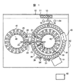
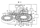
以下、図面を用いて本発明の実施の形態を説明する。図1は本発明の実施例の上面図、図2は斜視図である。反応ディスク36には反応容器35が円周上に並んでいる。反応ディスク36の内側に試薬ディスク42が、外側に試薬ディスク41が配置されている。試薬ディスク41,42にはそれぞれ複数の試薬容器40が円周上に載置可能である。1つの試薬容器40には2つの試薬が入る。反応ディスク36の近くにサンプル容器10を載せたラック11を移動する搬送機構12が設置されている。試薬ディスク41と試薬ディスク42の上にレール25,26が配置され、レール25にはレールと平行な方向および上下方向に移動可能な試薬プローブ20,21が、レール26にはレールと3軸方向に移動可能な試薬プローブ22,23が設置されている。試薬プローブ20,21,22,23はそれぞれ試薬用ポンプ24と接続している。反応容器35と搬送機構12の間には、回転及び上下動可能なサンプルプローブ15,16が設置されている。
【0026】
サンプルプローブ15,16は回転軸を中心に円弧を描きながら移動してサンプル容器から反応容器へのサンプル分注を交互に行う。お互いの動きが干渉しないよう、プローブ高さを変えられる機構を備え、分注タイミングと高さの調整を予めプログラムされた通りに実行するようになっている。
【0027】
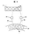
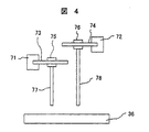
更に別の態様のサンプル分注機構の構成を図3および図4を用いて説明する。図3はサンプルプローブの軌跡を装置上面から示したもの、図4はサンプルプローブの構造を装置前面から示したもの、図5はサンプルプローブの移動機構を示す斜視図である。サンプルプローブ15,16はラック11上のサンプルプローブによる吸引位置にあるサンプル容器61と反応容器35のうちサンプルプローブにて試料吐出位置となる反応容器62に移動する。サンプルプローブ15は前記サンプル容器61と反応容器62に加え洗浄位置63の3個所に移動可能であり65はサンプルプローブ15の軌跡を示している。一方サンプルプローブ16は前記サンプル容器61と反応容器62に加え洗浄位置64の3箇所に移動可能であり66はサンプルプローブ16の軌跡を示している。
【0028】
サンプルプローブ15はサンプル容器61と反応容器62との前後方向の移動を図には示していない駆動源によりレール71に沿って移動可能でありさらに洗浄位置63とサンプル容器61および反応容器62との左右方向の移動を図には示していない駆動源によりレール73に沿って移動可能である。前後方向の移動動作と左右方向の移動動作とは、どちらか一方の動作に対し他方が追従して動作を行う。これによりサンプルプローブヘッド75はレール71とレール73により構成される平面内を移動可能となるとともに、上下動作機構を有するノズル77により3次元空間を移動可能となる。
【0029】
同様にサンプルプローブ16はサンプル容器61と反応容器62との前後方向の移動を図には示していない駆動源によりレール72に沿って移動可能でありさらに洗浄位置63とサンプル容器61および反応容器62との左右方向の移動を図には示していない駆動源によりレール74に沿って移動可能である。前後方向の移動動作と左右方向の移動動作とは、どちらか一方の動作に対し他方が追従して動作を行う。これによりサンプルプローブヘッド76はレール72とレール74により構成される平面内を移動可能となるとともに、上下動作機構を有するノズル78により3次元空間を移動可能となる。
【0030】
またサンプルプローブ15,16は液面検知機能および詰まり検知機能を有し、サンプルプローブ15,16はそれぞれサンプル用ポンプ14に接続している。サンプルプローブ15,16はそれぞれ独立な駆動系により制御されている。
【0031】
36の周囲には、攪拌装置30,31,光源50,検出光学装置51,容器洗浄機構45が配置されている。容器洗浄機構45は洗浄用ポンプ46に接続している。サンプルプローブ15,16,試薬プローブ20,21,22,23,攪拌装置30,31のそれぞれの動作範囲に洗浄ポート54が設置されている。サンプル用ポンプ14,試薬用ポンプ24,洗浄用ポンプ46,検出光学装置51,反応容器35,試薬ディスク41,試薬プローブ20,21,22,23,サンプルプローブ15,16はそれぞれコントローラ60に接続している。
【0032】
この装置を用いての分析手順を説明する。
【0033】
サンプル容器10には血液等の検査対象の試料が入れられ、ラック11に載せられて搬送機構12によって運ばれる。
【0034】
サンプルプローブ15または16によりサンプル容器61内の試料は採取された試料は、反応容器62へ分注される。
【0035】
サンプルプローブ15の初期位置は洗浄位置63でありサンプルプローブ16の初期位置は洗浄位置64である。
【0036】
サンプルプローブ15は試料吸引位置へレール71およびレール73上を移動し、試料容器61上でサンプルプローブヘッド75が下降動作を行い試料吸引後に上昇し反応容器62へ吸引した試料を吐出するために移動し、サンプルプローブ16は試料吸引位置61へレール72およびレール74上を移動し、試料容器61上でサンプルプローブヘッド76が下降動作を行い試料吸引後に上昇し反応容器62へ吸引した試料を吐出するために移動する。
【0037】
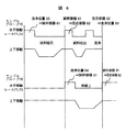
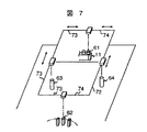
たとえば、サンプルプローブ15からサンプルを吸引する場合、図6に示したタイムチャートのようにサンプルプローブ15は試料吸引位置へ移動、試料吸引の後反応容器62へ吸引した試料を吐出するために移動する。サンプルプローブ15の反応容器62への移動とともにサンプルプローブ16は洗浄位置64からサンプル容器61へ移動を開始する。この際にサンプルプローブ15とサンプルプローブ16とはお互いがぶつからないようにするためにサンプルプローブ15は洗浄位置63を経由して反応容器62へと移動を行う。同様にサンプルプローブ16がサンプル容器61からの試料吸引を終えたら洗浄位置64を経由して反応容器62へ試料吐出のために移動する。これにより当該サンプル容器から試料を吸引する時間の短縮が可能となる。図6に示したタイムチャートの動作を行うためには2つのサンプリングプローブが交差しないように機構を配置すればよく、これを実現させる機構として前記図5で示した機構構成以外の実施例を図7,図8に示す。
【0038】
図7と図5との違いは、図5ではサンプルプローブの移動軌跡に沿った曲線のレール101を用いていたが、図7では平面内の駆動を行うためにレールを2軸(71,72)設けている点である。
【0039】
図8は図5において曲線レール101にて2つのサンプルプローブの干渉(接触)を回避していたのを直角に交わる2本のレールではなく鈍角に交差する2本の直線レールを用いることによりサンプルプローブヘッド75と76との干渉を避けている。
【0040】
また当該サンプル容器からの試料吸引が予定分終了した際には搬送機構12により次のサンプル容器がサンプル吸引位置にラック11を搬送する。
【0041】
また、図5,図7,図8のようにレールに沿って移動する分注機構にサンプルプローブが設けられているのではなく、該移動機構に分注アームを設け、該分注アームを回転移動または平行移動させることにより、分注可能な位置を調整可能とすることもできる。
【0042】
一定量の試薬が試薬ディスク41又は42に設置された試薬容器40から試薬プローブ20又は21又は22又は23から分注され、攪拌装置30,31にて攪拌し、一定時間反応した後検出光学装置51により測定され、測定結果として、図には明示されていない制御コンピュータに出力される。測定項目がさらに依頼されている場合は上記のサンプリングを繰り返し、サンプルプローブ15が反応容器35に採取した試料を吐出している最中にサンプルプローブ16がサンプル容器10から採取を行う。以後同一サンプル容器10の測定項目を終了した時点で次のサンプル容器10からサンプルプローブ15又は16にて試料が採取され、サンプルプローブ15又は16でラック11上にある全てのサンプル容器10について、設定された全ての測定項目のサンプリングが終了するまで繰り返される。
【0043】
サンプルプローブ15又は16と試薬プローブ20又は21又は22又は23とは任意の組み合わせが可能である。これによりサンプルプローブ15又は16のいずれかがなんらかの異常により動作の継続が不可能となった場合でも他方のサンプルプローブにて分析装置上に配置される全ての試薬項目に対し分析動作を継続することが可能となる。
【0044】
またサンプリングプローブ15又は16のいずれか一方がすでに異常があることがわかっている場合、異常があるサンプルプローブのみを有効として分析を開始することができる。
【0045】
またサンプルプローブ15または16いずれかにて、各々が有する詰まり検知機能によりサンプル容器10内の試料に詰まり要因が混入していると試料切れと判定された場合には、詰まりを検出したサンプルプローブは洗浄ポート54にて流路洗浄を行い、他方のサンプルプローブは該当試料からの採取動作を中止しラック11上の次のサンプル容器10からの試料採取に遷移することが可能である。状態判断により急遽ラック11上のサンプル容器10を試料採取位置への移動動作が間に合わない場合においても、サンプルプローブ15又は16は複数の位置より試料の採取が可能であるため必要以上の空きサイクルを発生させることなく分析動作を継続することが可能である。
【0046】
また特に幼児試料のようにサンプル容器内の試料が極端に少ない場合はサンプルプローブ15または16のいずれか一方のみを使用することで試料採取時に必要となる、サンプルプローブ内での薄まり防止のための反応容器35には吐出されず洗浄槽へ廃棄されるダミーを減らすことができる。
【0047】
【発明の効果】
以上に示したように、本発明において独立に動作可能である複数の試料分注装置を持つ分析装置では時間あたりの処理能力が高く付加価値の高い自動分析装置を提供できる。
【図面の簡単な説明】
【図1】本発明を適用した自動分析装置の上面図。
【図2】本発明を適用した自動分析装置の斜視図。
【図3】本発明のサンプル分注プローブの動作を上から見た図。
【図4】本発明のサンプル分注プローブを横から見た図。
【図5】本発明のサンプル分注プローブ機構の斜視図。
【図6】分注タイミングを示すタイミングチャート。
【図7】本発明の別の実施例を示す図。
【図8】本発明の別の実施例を示す図。
【符号の説明】
10…サンプル容器、11…ラック、12…搬送機構、14…サンプル用ポンプ、15,16…サンプルプローブ、20,21,22,23…試薬プローブ、24…試薬用ポンプ、25,26…レール、30,31…攪拌装置、35…反応容器、36…反応ディスク、40…試薬容器、41,42…試薬ディスク、45…容器洗浄機構、46…洗浄用ポンプ、50…光源、51…検出光学装置、54…洗浄ポート、60…コントローラ、61…サンプル吸引位置のサンプル容器、62…サンプル吐出位置の反応容器、63…サンプルプローブ1の洗浄位置、64…サンプルプローブ2の洗浄位置、65…サンプルプローブ15の軌跡、66…サンプルプローブ16の軌跡、71,72…サンプルプローブ16用レール1、73,74…サンプルプローブ16用レール2、75…サンプルプローブ15ヘッド、76…サンプルプローブ16用ヘッド、77…サンプルプローブ15用ノズル、78…サンプルプローブ16用ノズル。[0001]
BACKGROUND OF THE INVENTION
TECHNICAL FIELD The present invention relates to a sample dispensing mechanism and an automatic analyzer for performing qualitative and quantitative analysis of specific components in a sample by mixing the sample with a reagent, and in particular, a sample having a high dispensing processing capacity per hour. The present invention relates to a dispensing mechanism and an automatic analyzer equipped with the dispensing mechanism.
[0002]
[Prior art]
Taking an example of an automatic medical analyzer used for analysis of specific components in biological samples such as blood and urine, such an automatic analyzer is undertaken from a large hospital, small / medium hospital, or clinic with a large number of patients. This is an indispensable device for efficient analysis at the inspection center.
[0003]
Such an automatic analyzer is desired to be compact and capable of performing more types of analysis and having a high processing speed, and various types of automatic analyzers have been proposed.
[0004]
One means for increasing the processing speed is to increase the sample dispensing speed.
[0005]
Further,
[0006]
[Patent Document 1]
Japanese Patent Laid-Open No. 3-140869 [Patent Document 2]
Japanese Patent Laid-Open No. 2001-66316
[Problems to be solved by the invention]
According to the method described in
[0008]
Further, in the method described in
[0009]
An object of the present invention is to provide a sample dispensing probe that includes a sample dispensing probe capable of independently dispensing a plurality of dispensing probes, improves dispensing speed, and enables flexible dispensing operation timing. It is to provide an automatic analyzer equipped with the same.
[0010]
The sample dispensing probe of the present invention is suitable for an automatic medical analyzer, but it is needless to say that the sample dispensing probe can be applied to an inorganic / organic sample analyzer or the like.
[0011]
[Means for Solving the Problems]
The problem solving means of the present invention is as follows.
[0012]
A plurality of sample containers for storing the sample to be analyzed can be placed, and a sample container mounting mechanism having a mechanism capable of changing the arrangement of the plurality of sample containers, and a plurality of reaction containers for mixing the sample to be analyzed and the reagent are provided. A reaction container mounting mechanism having a mechanism that can be placed and capable of changing the arrangement of the plurality of reaction containers; a sample dispensing mechanism for dispensing a sample from the sample container and discharging the sample to the reaction container; In a sample dispensing apparatus comprising:
The sample dispensing apparatus includes a plurality of nozzles for sample separation and discharge, and the nozzles can independently move the nozzle for sample separation and discharge, and the nozzles. Are each provided with a mechanism capable of moving independently between the sample container and the reaction container.
[0013]
The sample container mounting mechanism may be of any form as long as the position of the sample container can be moved. For example, the thing provided with the sample disk which arrange | positions several sample containers on the circumference may be sufficient. In this case, although it is expressed as a sample disk, it is not always necessary to have a disk shape. Therefore, the expression “on the circumference of the disk” is used, but in the case of a disk-shaped disk, it can be read as “on the circumference”.
[0014]
Moreover, the thing of the form which uses the rack which can mount one or more sample containers and moves this rack may be sufficient.
[0015]
The same applies to the reaction vessel mounting mechanism. It may be in the form of a reaction disk, or the reaction vessel may be moved linearly.
[0016]
DETAILED DESCRIPTION OF THE INVENTION
Each sample dispensing mechanism of the present invention repeats the operation of collecting a sample and discharging the sample into the reaction vessel. By having multiple nozzles, it is possible to fill the waiting time for sample collection by sampling other samples while one sample dispensing mechanism discharges the sample to the reaction disk after sample collection. Thus, high-speed processing can be realized.
[0017]
Since multiple sample dispensing mechanisms can be independently dispensed, frequent sampling operations can be performed from the sample container.With this, the movement time of the sample container to the sampling position is shortened. Although there is no time to move to a predetermined location, which causes a reduction in processing capacity, it is possible to prevent a decrease in processing capacity by allowing each sample dispensing mechanism to collect from a plurality of sample collection positions.
[0018]
The nozzle only needs to have a moving mechanism capable of reciprocating between the sample collection position and the reaction disk, and the movement trajectory of the sample dispensing mechanism may be linear or curved. It is necessary to have means that do not interfere with each other in order for the dispensing mechanism to be able to operate independently. For example, when the sample dispensing mechanism operates in the same plane, an escape position is provided on the operation path of the sample dispensing mechanism so as not to restrain the mutual movement between the sample collection position and the reaction disk. Position the mechanism so that the trajectory does not interfere. Alternatively, the moving parts of the mechanism are arranged vertically so as not to interfere with each other. Alternatively, a mechanism may be considered in which a rotation shaft is provided at the midpoint between the sample collection position and the reaction disk, and a plurality of sample dispensing mechanisms are moved to the sample collection position or the reaction disk by this rotation shaft. In the case of movement by a rotating shaft, each sample dispensing mechanism may have moving means other than the rotating shaft in order to move the sample dispensing mechanism to a plurality of sample collection positions or a plurality of reaction disk positions.
[0019]
Further, the nozzle may be provided with a liquid level detection function, and the liquid level detection function may be used to confirm whether or not there is a minimum number of samples for reliably collecting a sample in the sample container. In the case of an analyzer having a plurality of sample dispensing mechanisms, based on the determination result when it is determined that there is not enough sample in the sample container to reliably collect samples in any sample dispensing mechanism. Next, the sample dispensing device that collects the same sample next time can reduce unnecessary operations by stopping the sampling from the planned sample container and changing the sampling source to the next sample container It becomes.
[0020]
Further, the nozzle may be provided with a clogging detection function, and the clogging detection function may be used to check whether a clogging factor in the flow path is present in the sample container. In the case of an analyzer having a plurality of sample dispensing mechanisms, if a clogging factor is present in the sample container by any sample dispensing mechanism, the next sample is collected from the same sample based on the determination result. The dispensing apparatus can reduce the wasteful operation by stopping the sampling from the sample container and changing the sampling source to the sample container to be sampled next.
[0021]
In addition, even if the nozzle becomes inoperable due to some abnormality, it has a plurality of sample dispensing mechanisms that can operate independently. The analysis operation can be continued by the sample dispensing mechanism in operation.
[0022]
Further, if at least one of the plurality of nozzles is operable, the analysis can be performed by operating only the operable sample dispensing mechanism among the plurality of sample dispensing mechanisms.
[0023]
In sample dispensing, the dummy is sucked in addition to the amount dispensed into the reaction vessel in order to avoid thinning in the flow path. This dummy is finally discharged and discarded into the cleaning tank. By having multiple sample dispensing mechanisms, the processing capacity will increase, but if the sample volume is extremely small, such as a pediatric sample, all items requested for that sample will be analyzed even if the processing capacity is reduced. Is more valuable. For example, all items requested even in the case of a small amount of sample by collecting and dispensing a sample only with a specific sample dispensing mechanism instead of using all the sample dispensing mechanisms according to the information of the sample container Can be analyzed. When the operation is separated according to the sample container type as in the above example, for example, by enabling / disabling the function from the operation screen, a device with higher added value can be provided.
[0024]
Higher processing speed is possible with a larger number of nozzles, but there is a problem with space, such as the need to provide a relief position between mechanisms and an increase in the reagent dispensing mechanism for dispensing reagents after dispensing the sample into the reaction container. Therefore, it is desirable to select appropriately according to the processing capacity.
[0025]
Hereinafter, embodiments of the present invention will be described with reference to the drawings. FIG. 1 is a top view of an embodiment of the present invention, and FIG. 2 is a perspective view.
[0026]
The sample probes 15 and 16 move while drawing an arc around the rotation axis, and alternately perform sample dispensing from the sample container to the reaction container. A mechanism capable of changing the probe height is provided so that the movements of each other do not interfere with each other, and the adjustment of the dispensing timing and the height is executed as programmed in advance.
[0027]
The configuration of a sample dispensing mechanism according to another embodiment will be described with reference to FIGS. FIG. 3 shows the locus of the sample probe from the top of the apparatus, FIG. 4 shows the structure of the sample probe from the front of the apparatus, and FIG. 5 is a perspective view showing the moving mechanism of the sample probe. The sample probes 15 and 16 are moved from the
[0028]
The
[0029]
Similarly, the
[0030]
The sample probes 15 and 16 have a liquid level detection function and a clogging detection function, and the sample probes 15 and 16 are connected to the
[0031]
Around 36, stirring
[0032]
An analysis procedure using this apparatus will be described.
[0033]
A sample to be inspected, such as blood, is placed in the
[0034]
The sample collected in the
[0035]
The initial position of the
[0036]
The
[0037]
For example, when a sample is aspirated from the
[0038]
The difference between FIG. 7 and FIG. 5 is that, in FIG. 5, a
[0039]
FIG. 8 is a sample obtained by using two linear rails crossing an obtuse angle instead of two rails crossing at right angles, in FIG. Interference between the probe heads 75 and 76 is avoided.
[0040]
When the sample suction from the sample container is completed for a predetermined amount, the
[0041]
In addition, the sample probe is not provided in the dispensing mechanism that moves along the rail as shown in FIGS. 5, 7, and 8, but a dispensing arm is provided in the moving mechanism, and the dispensing arm is rotated. It is also possible to adjust the position where dispensing is possible by moving or translating.
[0042]
A certain amount of reagent is dispensed from the
[0043]
Any combination of the
[0044]
When it is already known that either one of the sampling probes 15 or 16 is abnormal, the analysis can be started with only the sample probe having the abnormality being effective.
[0045]
If it is determined that either of the sample probes 15 or 16 has a clogging factor mixed in the sample in the
[0046]
Moreover, especially when there are extremely few samples in the sample container such as an infant sample, it is necessary to use only one of the sample probes 15 and 16 to prevent thinning in the sample probe, which is necessary when collecting samples. It is possible to reduce the number of dummies that are not discharged into the
[0047]
【The invention's effect】
As described above, in the present invention, an analyzer having a plurality of sample dispensing devices that can operate independently can provide an automatic analyzer with high processing capacity per time and high added value.
[Brief description of the drawings]
FIG. 1 is a top view of an automatic analyzer to which the present invention is applied.
FIG. 2 is a perspective view of an automatic analyzer to which the present invention is applied.
FIG. 3 is a top view of the operation of the sample dispensing probe of the present invention.
FIG. 4 is a side view of the sample dispensing probe of the present invention.
FIG. 5 is a perspective view of a sample dispensing probe mechanism of the present invention.
FIG. 6 is a timing chart showing dispensing timing.
FIG. 7 is a diagram showing another embodiment of the present invention.
FIG. 8 is a diagram showing another embodiment of the present invention.
[Explanation of symbols]
DESCRIPTION OF
Claims (5)
該サンプルプローブ毎に設けられ、該サンプルプローブを平面内で移動させるためのレールと、該サンプルプローブを該レールに沿って移動させるサンプルプローブ駆動機構と、
を備え、
更に前記サンプルプローブヘッドの移動軌跡は閉じたループを形成し、該ループの軌跡上には、試料容器と反応容器を位置付けることができ、前記複数のサンプルプローブを該試料容器と該反応容器の間で交互に往復させるように前記サンプルプローブ駆動機構を制御する制御手段を備えたことを特徴とする自動分析装置。A plurality of sample probes each provided with a nozzle for dispensing a sample on each sample probe head;
A rail provided for each sample probe for moving the sample probe in a plane, and a sample probe driving mechanism for moving the sample probe along the rail;
Equipped with a,
Furthermore, the movement trajectory of the sample probe head forms a closed loop, and the sample container and the reaction container can be positioned on the trajectory of the loop, and the plurality of sample probes are placed between the sample container and the reaction container. An automatic analyzer comprising control means for controlling the sample probe driving mechanism so as to reciprocate alternately .
前記閉じたループが、上方からみて概楕円形状,四角形状,ひし形形状のいずれかをしていることを特徴とする自動分析装置。The automatic analyzer according to claim 1 , wherein
The automatic analyzer according to claim 1, wherein the closed loop has an approximately elliptical shape, a square shape, or a rhombus shape as viewed from above.
前記複数のサンプルプローブの少なくとも1つのノズルに容器中の試料の液面を検知する液面機能を備え、該液面検知機能で検知した液面に関する情報を他のノズルに伝達する機能を備えたことを特徴とする自動分析装置。The automatic analyzer according to claim 1 or 2 ,
At least one nozzle of the plurality of sample probes has a liquid level function of detecting the liquid level of the sample in the container, and has a function of transmitting information on the liquid level detected by the liquid level detection function to other nozzles. An automatic analyzer characterized by that.
前記複数のサンプルプローブの少なくとも1つのノズルに、ノズルの詰まりを検知する詰まり検知機能を備え、
試料内の詰まり要因の混入有無情報を他のノズルに伝達する機能を備えたことを特徴とする自動分析装置。The automatic analyzer according to claim 1 or 2 ,
At least one nozzle of the plurality of sample probes has a clogging detection function for detecting clogging of the nozzle,
An automatic analyzer having a function of transmitting information on presence or absence of clogging factors in a sample to another nozzle.
前記複数のサンプルプローブの任意の前記ノズルを使用停止とし他のノズルにて試料分注を実行できる機構を備えたことを特徴とする自動分析装置。The automatic analyzer according to claim 1 or 2 ,
An automatic analyzer comprising a mechanism capable of discontinuing use of any nozzle of the plurality of sample probes and performing sample dispensing using another nozzle.
Priority Applications (7)
| Application Number | Priority Date | Filing Date | Title |
|---|---|---|---|
| JP2003074751A JP3972012B2 (en) | 2003-03-19 | 2003-03-19 | Sample dispensing mechanism and automatic analyzer equipped with the same |
| EP04002367.3A EP1460432B1 (en) | 2003-03-19 | 2004-02-03 | Sample dispensing apparatus and automatic analyzer including the same |
| US10/780,743 US7824915B2 (en) | 2003-03-19 | 2004-02-19 | Sample dispensing apparatus and automatic analyzer including the same |
| US12/895,040 US8197754B2 (en) | 2003-03-19 | 2010-09-30 | Sample dispensing apparatus and automatic analyzer including the same |
| US13/473,666 US8691148B2 (en) | 2003-03-19 | 2012-05-17 | Sample dispensing apparatus and automatic analyzer including the same |
| US14/185,037 US9817013B2 (en) | 2003-03-19 | 2014-02-20 | Sample dispensing apparatus and automatic analyzer including the same |
| US15/730,947 US10309979B2 (en) | 2003-03-19 | 2017-10-12 | Sample dispensing apparatus and automatic analyzer including the same |
Applications Claiming Priority (1)
| Application Number | Priority Date | Filing Date | Title |
|---|---|---|---|
| JP2003074751A JP3972012B2 (en) | 2003-03-19 | 2003-03-19 | Sample dispensing mechanism and automatic analyzer equipped with the same |
Related Child Applications (3)
| Application Number | Title | Priority Date | Filing Date |
|---|---|---|---|
| JP2006174720A Division JP4366380B2 (en) | 2006-06-26 | 2006-06-26 | Automatic analyzer |
| JP2006174722A Division JP4416763B2 (en) | 2006-06-26 | 2006-06-26 | Automatic analyzer |
| JP2006174721A Division JP4393481B2 (en) | 2006-06-26 | 2006-06-26 | Automatic analyzer |
Publications (2)
| Publication Number | Publication Date |
|---|---|
| JP2004279356A JP2004279356A (en) | 2004-10-07 |
| JP3972012B2 true JP3972012B2 (en) | 2007-09-05 |
Family
ID=32821335
Family Applications (1)
| Application Number | Title | Priority Date | Filing Date |
|---|---|---|---|
| JP2003074751A Expired - Lifetime JP3972012B2 (en) | 2003-03-19 | 2003-03-19 | Sample dispensing mechanism and automatic analyzer equipped with the same |
Country Status (3)
| Country | Link |
|---|---|
| US (5) | US7824915B2 (en) |
| EP (1) | EP1460432B1 (en) |
| JP (1) | JP3972012B2 (en) |
Cited By (2)
| Publication number | Priority date | Publication date | Assignee | Title |
|---|---|---|---|---|
| JP2012083227A (en) * | 2010-10-12 | 2012-04-26 | Sysmex Corp | Sample analyzer |
| EP3761040A4 (en) * | 2018-02-28 | 2021-12-08 | Hitachi High-Tech Corporation | AUTOMATED ANALYSIS DEVICE |
Families Citing this family (31)
| Publication number | Priority date | Publication date | Assignee | Title |
|---|---|---|---|---|
| JP4812352B2 (en) * | 2005-07-21 | 2011-11-09 | 株式会社東芝 | Automatic analyzer and its dispensing method |
| JP2008180538A (en) * | 2007-01-23 | 2008-08-07 | Olympus Corp | Analyzer |
| JP2008209339A (en) * | 2007-02-28 | 2008-09-11 | Hitachi High-Technologies Corp | Automatic analyzer |
| JP5583337B2 (en) * | 2007-12-28 | 2014-09-03 | ベックマン コールター, インコーポレイテッド | Automatic analyzer and its dispensing method |
| ES2371185B1 (en) * | 2008-05-30 | 2012-08-07 | Grifols, S.A. | DEVICE FOR THE AUTOMATIC PERFORMANCE OF SAMPLE ANALYSIS IN GEL CARDS. |
| CN101721937B (en) | 2008-10-31 | 2012-06-27 | 深圳迈瑞生物医疗电子股份有限公司 | Stirring system and working method thereof |
| JP5373561B2 (en) * | 2008-11-17 | 2013-12-18 | シスメックス株式会社 | Conveying device and sample analyzer using the same |
| DE112010000784B4 (en) * | 2009-01-29 | 2013-10-31 | Hitachi High-Technologies Corporation | Automatic analyzer |
| JP5757694B2 (en) * | 2010-05-31 | 2015-07-29 | アークレイ株式会社 | Conveying device, conveying method, conveying program, analyzing device, analyzing method, and sample analyzing program |
| EP2752670A2 (en) * | 2010-07-23 | 2014-07-09 | Beckman Coulter, Inc. | System or method of including analytical units |
| DE102010037084A1 (en) * | 2010-08-20 | 2012-02-23 | LCTech GmbH | Sample conditioning system and a method for processing a sample |
| US9442128B2 (en) | 2011-10-18 | 2016-09-13 | Hitachi High-Technologies Corporation | Automated analyzer |
| JP2014532877A (en) | 2011-11-01 | 2014-12-08 | サウジ アラビアン オイル カンパニー | Multi cuvette automatic sampler for optical measurement |
| EP2746775B1 (en) * | 2012-12-19 | 2019-09-04 | F.Hoffmann-La Roche Ag | Device and process for transferring reaction vessels |
| JP6153759B2 (en) * | 2013-04-10 | 2017-06-28 | 株式会社日立ハイテクノロジーズ | Automatic analyzer |
| CN103675316A (en) * | 2013-12-24 | 2014-03-26 | 苏州长光华医生物医学工程有限公司 | Full-automatic sample-adding device for blood-type testing instrument |
| JP6521567B2 (en) * | 2014-02-27 | 2019-05-29 | キヤノンメディカルシステムズ株式会社 | Clinical examination equipment |
| JP6104843B2 (en) * | 2014-03-28 | 2017-03-29 | シスメックス株式会社 | Sample analyzer |
| CN106471374B (en) * | 2014-07-18 | 2018-12-14 | 株式会社日立高新技术 | Liquid stirring method |
| US11175301B2 (en) * | 2015-08-28 | 2021-11-16 | Hitachi High-Tech Corporation | Automatic analyzer and reagent bottle loading method |
| JP6611569B2 (en) * | 2015-11-24 | 2019-11-27 | キヤノンメディカルシステムズ株式会社 | Automatic analyzer |
| WO2017199432A1 (en) * | 2016-05-20 | 2017-11-23 | 株式会社島津製作所 | Preprocessing device and analysis system provided with preprocessing device |
| JP6934061B2 (en) * | 2017-03-09 | 2021-09-08 | ホロジック, インコーポレイテッドHologic, Inc. | Automatic preparation system and method for biological specimens |
| CN111989558A (en) | 2018-03-16 | 2020-11-24 | 因为傲可值有限公司 | Sample processing system and method for automated processing of histological samples |
| JP6843800B2 (en) * | 2018-06-19 | 2021-03-17 | 日本電子株式会社 | Automatic analyzer and automatic analysis method |
| CN109061214B (en) * | 2018-10-31 | 2023-12-19 | 江苏卓微生物科技有限公司 | Porous sample injection device |
| EP3961224A4 (en) * | 2019-04-26 | 2023-01-18 | Hitachi High-Tech Corporation | AUTOMATIC ANALYSIS DEVICE AND METHOD FOR DESIGNING AUTOMATIC ANALYSIS DEVICE |
| WO2021054456A1 (en) * | 2019-09-20 | 2021-03-25 | 株式会社日立ハイテク | Automatic analysis device |
| CN111781338A (en) * | 2020-07-10 | 2020-10-16 | 屈梅 | Special blood detector of hematology department |
| CN112881356B (en) * | 2021-01-18 | 2022-06-28 | 上海雄图生物科技有限公司 | High-flux fluorescence immunoassay quantitative POCT analysis device |
| CN114384262B (en) * | 2021-12-30 | 2025-09-26 | 深圳市新产业生物医学工程股份有限公司 | Liquid aspiration device and sample analyzer |
Family Cites Families (21)
| Publication number | Priority date | Publication date | Assignee | Title |
|---|---|---|---|---|
| US4276260A (en) * | 1980-01-28 | 1981-06-30 | Coulter Electronics, Inc. | Fluid transfer mechanism |
| JPS5782769A (en) * | 1980-11-10 | 1982-05-24 | Hitachi Ltd | Automatic analyzing device |
| AU585033B2 (en) * | 1986-07-04 | 1989-06-08 | Tosoh Corporation | Quantitative dispenser for a liquid |
| JPH06103315B2 (en) * | 1987-08-14 | 1994-12-14 | 株式会社東芝 | Dispensing nozzle device of automatic chemical analyzer |
| US5178834A (en) * | 1989-07-19 | 1993-01-12 | Tosoh Corporation | Automatic immunoassay analyzer |
| JPH03140869A (en) * | 1989-10-26 | 1991-06-14 | Toshiba Corp | Automatic apparatus for chemical analysis |
| EP0488247B1 (en) * | 1990-11-28 | 1997-04-23 | Hitachi, Ltd. | Analyzing method and apparatus for liquid sample |
| DE59306558D1 (en) * | 1992-04-06 | 1997-07-03 | Hoffmann La Roche | Analyzer |
| EP0601213A1 (en) * | 1992-10-29 | 1994-06-15 | Hamilton Bonaduz AG | Transportdevice for goods |
| JP3140869B2 (en) | 1992-12-03 | 2001-03-05 | 株式会社東芝 | Printed wiring board design support system |
| CA2113785A1 (en) * | 1993-01-29 | 1994-07-30 | Teruaki Itoh | Sample sorting apparatus |
| AU4982093A (en) * | 1993-08-31 | 1995-03-22 | Abbott Laboratories | Pipetting apparatus equipped with closure detection function |
| DE69515565T2 (en) * | 1994-07-15 | 2000-11-02 | Dade Chemistry Systems Inc., Deerfield | Analyzer |
| US5885529A (en) * | 1996-06-28 | 1999-03-23 | Dpc Cirrus, Inc. | Automated immunoassay analyzer |
| US5942694A (en) * | 1996-11-12 | 1999-08-24 | Beckman Instruments, Inc. | Pressure detector for chemical analyzers |
| JP2001066316A (en) | 1999-08-30 | 2001-03-16 | Olympus Optical Co Ltd | Dispensing apparatus |
| US7015042B2 (en) * | 2001-07-27 | 2006-03-21 | Dade Behring Inc. | Increasing throughput in an automatic clinical analyzer by partitioning assays according to type |
| JP5193408B2 (en) * | 2001-09-13 | 2013-05-08 | ベックマン コールター, インコーポレイテッド | Automatic analyzer |
| CA2473860A1 (en) * | 2002-01-25 | 2003-08-07 | Innovadyne Technologies, Inc. | Low volume, non-contact liquid dispensing method |
| JP3740428B2 (en) * | 2002-03-29 | 2006-02-01 | アロカ株式会社 | Sample pretreatment system |
| US20040096368A1 (en) * | 2002-06-28 | 2004-05-20 | Igen International, Inc. | Assay systems and components |
-
2003
- 2003-03-19 JP JP2003074751A patent/JP3972012B2/en not_active Expired - Lifetime
-
2004
- 2004-02-03 EP EP04002367.3A patent/EP1460432B1/en not_active Expired - Lifetime
- 2004-02-19 US US10/780,743 patent/US7824915B2/en active Active
-
2010
- 2010-09-30 US US12/895,040 patent/US8197754B2/en not_active Expired - Fee Related
-
2012
- 2012-05-17 US US13/473,666 patent/US8691148B2/en not_active Expired - Lifetime
-
2014
- 2014-02-20 US US14/185,037 patent/US9817013B2/en not_active Expired - Fee Related
-
2017
- 2017-10-12 US US15/730,947 patent/US10309979B2/en not_active Expired - Lifetime
Cited By (3)
| Publication number | Priority date | Publication date | Assignee | Title |
|---|---|---|---|---|
| JP2012083227A (en) * | 2010-10-12 | 2012-04-26 | Sysmex Corp | Sample analyzer |
| EP3761040A4 (en) * | 2018-02-28 | 2021-12-08 | Hitachi High-Tech Corporation | AUTOMATED ANALYSIS DEVICE |
| US11913966B2 (en) | 2018-02-28 | 2024-02-27 | Hitachi High-Tech Corporation | Automated analysis device |
Also Published As
| Publication number | Publication date |
|---|---|
| US20140170022A1 (en) | 2014-06-19 |
| US8197754B2 (en) | 2012-06-12 |
| EP1460432B1 (en) | 2013-06-05 |
| US20120230873A1 (en) | 2012-09-13 |
| US10309979B2 (en) | 2019-06-04 |
| US9817013B2 (en) | 2017-11-14 |
| EP1460432A1 (en) | 2004-09-22 |
| US7824915B2 (en) | 2010-11-02 |
| US8691148B2 (en) | 2014-04-08 |
| US20180038882A1 (en) | 2018-02-08 |
| US20110014085A1 (en) | 2011-01-20 |
| US20040245275A1 (en) | 2004-12-09 |
| JP2004279356A (en) | 2004-10-07 |
Similar Documents
| Publication | Publication Date | Title |
|---|---|---|
| JP3972012B2 (en) | Sample dispensing mechanism and automatic analyzer equipped with the same | |
| JP4221349B2 (en) | Automatic analyzer | |
| EP3671218A1 (en) | Blood analyzer and control method therefor | |
| JP3677298B2 (en) | Automatic chemical analyzer | |
| US7850914B2 (en) | Specimen-transport module for a multi-instrument clinical workcell | |
| JP3914837B2 (en) | Automatic analyzer | |
| JP5286120B2 (en) | Automatic analyzer | |
| JP2004333259A (en) | Automatic analyzer | |
| JPH05240868A (en) | Automatic analyzer for specimen | |
| JP2010501859A (en) | Automated patient sample storage and reprocessing system in an automated clinical analyzer | |
| WO2012105398A1 (en) | Automatic analyzing device | |
| JPH04115136A (en) | Particle measuring apparatus | |
| JP5661259B2 (en) | Automatic analyzer | |
| JP4929317B2 (en) | Automatic analyzer | |
| JP4416763B2 (en) | Automatic analyzer | |
| JP6521567B2 (en) | Clinical examination equipment | |
| JP4393481B2 (en) | Automatic analyzer | |
| JP2008209339A (en) | Automatic analyzer | |
| JP4366380B2 (en) | Automatic analyzer | |
| JP4783170B2 (en) | Automatic analyzer | |
| JP4644731B2 (en) | Automatic analyzer | |
| WO2023122970A1 (en) | Medical point-of-care testing device | |
| JP2004117221A (en) | Dispensing apparatus | |
| WO2023122973A1 (en) | Multifunctional sample analysis device | |
| JP4146873B2 (en) | Automatic analyzer |
Legal Events
| Date | Code | Title | Description |
|---|---|---|---|
| A621 | Written request for application examination |
Free format text: JAPANESE INTERMEDIATE CODE: A621 Effective date: 20050511 |
|
| A521 | Request for written amendment filed |
Free format text: JAPANESE INTERMEDIATE CODE: A523 Effective date: 20050511 |
|
| A977 | Report on retrieval |
Free format text: JAPANESE INTERMEDIATE CODE: A971007 Effective date: 20060227 |
|
| A131 | Notification of reasons for refusal |
Free format text: JAPANESE INTERMEDIATE CODE: A131 Effective date: 20060425 |
|
| RD02 | Notification of acceptance of power of attorney |
Free format text: JAPANESE INTERMEDIATE CODE: A7422 Effective date: 20060511 |
|
| RD04 | Notification of resignation of power of attorney |
Free format text: JAPANESE INTERMEDIATE CODE: A7424 Effective date: 20060511 |
|
| A521 | Request for written amendment filed |
Free format text: JAPANESE INTERMEDIATE CODE: A523 Effective date: 20060626 |
|
| A02 | Decision of refusal |
Free format text: JAPANESE INTERMEDIATE CODE: A02 Effective date: 20061212 |
|
| A521 | Request for written amendment filed |
Free format text: JAPANESE INTERMEDIATE CODE: A523 Effective date: 20070112 |
|
| A521 | Request for written amendment filed |
Free format text: JAPANESE INTERMEDIATE CODE: A523 Effective date: 20070213 |
|
| A911 | Transfer to examiner for re-examination before appeal (zenchi) |
Free format text: JAPANESE INTERMEDIATE CODE: A911 Effective date: 20070320 |
|
| TRDD | Decision of grant or rejection written | ||
| A01 | Written decision to grant a patent or to grant a registration (utility model) |
Free format text: JAPANESE INTERMEDIATE CODE: A01 Effective date: 20070605 |
|
| A61 | First payment of annual fees (during grant procedure) |
Free format text: JAPANESE INTERMEDIATE CODE: A61 Effective date: 20070611 |
|
| R150 | Certificate of patent or registration of utility model |
Free format text: JAPANESE INTERMEDIATE CODE: R150 Ref document number: 3972012 Country of ref document: JP Free format text: JAPANESE INTERMEDIATE CODE: R150 |
|
| FPAY | Renewal fee payment (event date is renewal date of database) |
Free format text: PAYMENT UNTIL: 20110615 Year of fee payment: 4 |
|
| FPAY | Renewal fee payment (event date is renewal date of database) |
Free format text: PAYMENT UNTIL: 20110615 Year of fee payment: 4 |
|
| FPAY | Renewal fee payment (event date is renewal date of database) |
Free format text: PAYMENT UNTIL: 20120615 Year of fee payment: 5 |
|
| FPAY | Renewal fee payment (event date is renewal date of database) |
Free format text: PAYMENT UNTIL: 20120615 Year of fee payment: 5 |
|
| FPAY | Renewal fee payment (event date is renewal date of database) |
Free format text: PAYMENT UNTIL: 20130615 Year of fee payment: 6 |
|
| S531 | Written request for registration of change of domicile |
Free format text: JAPANESE INTERMEDIATE CODE: R313531 |
|
| S533 | Written request for registration of change of name |
Free format text: JAPANESE INTERMEDIATE CODE: R313533 |
|
| R350 | Written notification of registration of transfer |
Free format text: JAPANESE INTERMEDIATE CODE: R350 |
|
| EXPY | Cancellation because of completion of term |