JP3971696B2 - Method for manufacturing friction plate for wet clutch - Google Patents
Method for manufacturing friction plate for wet clutch Download PDFInfo
- Publication number
- JP3971696B2 JP3971696B2 JP2002365712A JP2002365712A JP3971696B2 JP 3971696 B2 JP3971696 B2 JP 3971696B2 JP 2002365712 A JP2002365712 A JP 2002365712A JP 2002365712 A JP2002365712 A JP 2002365712A JP 3971696 B2 JP3971696 B2 JP 3971696B2
- Authority
- JP
- Japan
- Prior art keywords
- friction material
- strip
- friction
- shaped
- core plate
- Prior art date
- Legal status (The legal status is an assumption and is not a legal conclusion. Google has not performed a legal analysis and makes no representation as to the accuracy of the status listed.)
- Expired - Lifetime
Links
Images


Classifications
-
- F—MECHANICAL ENGINEERING; LIGHTING; HEATING; WEAPONS; BLASTING
- F16—ENGINEERING ELEMENTS AND UNITS; GENERAL MEASURES FOR PRODUCING AND MAINTAINING EFFECTIVE FUNCTIONING OF MACHINES OR INSTALLATIONS; THERMAL INSULATION IN GENERAL
- F16D—COUPLINGS FOR TRANSMITTING ROTATION; CLUTCHES; BRAKES
- F16D13/00—Friction clutches
- F16D13/58—Details
- F16D13/60—Clutching elements
- F16D13/64—Clutch-plates; Clutch-lamellae
- F16D13/648—Clutch-plates; Clutch-lamellae for clutches with multiple lamellae
-
- B—PERFORMING OPERATIONS; TRANSPORTING
- B23—MACHINE TOOLS; METAL-WORKING NOT OTHERWISE PROVIDED FOR
- B23P—METAL-WORKING NOT OTHERWISE PROVIDED FOR; COMBINED OPERATIONS; UNIVERSAL MACHINE TOOLS
- B23P15/00—Making specific metal objects by operations not covered by a single other subclass or a group in this subclass
-
- F—MECHANICAL ENGINEERING; LIGHTING; HEATING; WEAPONS; BLASTING
- F16—ENGINEERING ELEMENTS AND UNITS; GENERAL MEASURES FOR PRODUCING AND MAINTAINING EFFECTIVE FUNCTIONING OF MACHINES OR INSTALLATIONS; THERMAL INSULATION IN GENERAL
- F16D—COUPLINGS FOR TRANSMITTING ROTATION; CLUTCHES; BRAKES
- F16D69/00—Friction linings; Attachment thereof; Selection of coacting friction substances or surfaces
- F16D2069/004—Profiled friction surfaces, e.g. grooves, dimples
-
- F—MECHANICAL ENGINEERING; LIGHTING; HEATING; WEAPONS; BLASTING
- F16—ENGINEERING ELEMENTS AND UNITS; GENERAL MEASURES FOR PRODUCING AND MAINTAINING EFFECTIVE FUNCTIONING OF MACHINES OR INSTALLATIONS; THERMAL INSULATION IN GENERAL
- F16D—COUPLINGS FOR TRANSMITTING ROTATION; CLUTCHES; BRAKES
- F16D69/00—Friction linings; Attachment thereof; Selection of coacting friction substances or surfaces
- F16D69/04—Attachment of linings
- F16D2069/0425—Attachment methods or devices
- F16D2069/0491—Tools, machines, processes
-
- F—MECHANICAL ENGINEERING; LIGHTING; HEATING; WEAPONS; BLASTING
- F16—ENGINEERING ELEMENTS AND UNITS; GENERAL MEASURES FOR PRODUCING AND MAINTAINING EFFECTIVE FUNCTIONING OF MACHINES OR INSTALLATIONS; THERMAL INSULATION IN GENERAL
- F16D—COUPLINGS FOR TRANSMITTING ROTATION; CLUTCHES; BRAKES
- F16D2250/00—Manufacturing; Assembly
-
- F—MECHANICAL ENGINEERING; LIGHTING; HEATING; WEAPONS; BLASTING
- F16—ENGINEERING ELEMENTS AND UNITS; GENERAL MEASURES FOR PRODUCING AND MAINTAINING EFFECTIVE FUNCTIONING OF MACHINES OR INSTALLATIONS; THERMAL INSULATION IN GENERAL
- F16D—COUPLINGS FOR TRANSMITTING ROTATION; CLUTCHES; BRAKES
- F16D65/00—Parts or details
- F16D65/02—Braking members; Mounting thereof
- F16D65/12—Discs; Drums for disc brakes
- F16D65/127—Discs; Drums for disc brakes characterised by properties of the disc surface; Discs lined with friction material
-
- Y—GENERAL TAGGING OF NEW TECHNOLOGICAL DEVELOPMENTS; GENERAL TAGGING OF CROSS-SECTIONAL TECHNOLOGIES SPANNING OVER SEVERAL SECTIONS OF THE IPC; TECHNICAL SUBJECTS COVERED BY FORMER USPC CROSS-REFERENCE ART COLLECTIONS [XRACs] AND DIGESTS
- Y10—TECHNICAL SUBJECTS COVERED BY FORMER USPC
- Y10T—TECHNICAL SUBJECTS COVERED BY FORMER US CLASSIFICATION
- Y10T156/00—Adhesive bonding and miscellaneous chemical manufacture
- Y10T156/10—Methods of surface bonding and/or assembly therefor
- Y10T156/1052—Methods of surface bonding and/or assembly therefor with cutting, punching, tearing or severing
- Y10T156/1062—Prior to assembly
- Y10T156/1067—Continuous longitudinal slitting
-
- Y—GENERAL TAGGING OF NEW TECHNOLOGICAL DEVELOPMENTS; GENERAL TAGGING OF CROSS-SECTIONAL TECHNOLOGIES SPANNING OVER SEVERAL SECTIONS OF THE IPC; TECHNICAL SUBJECTS COVERED BY FORMER USPC CROSS-REFERENCE ART COLLECTIONS [XRACs] AND DIGESTS
- Y10—TECHNICAL SUBJECTS COVERED BY FORMER USPC
- Y10T—TECHNICAL SUBJECTS COVERED BY FORMER US CLASSIFICATION
- Y10T156/00—Adhesive bonding and miscellaneous chemical manufacture
- Y10T156/10—Methods of surface bonding and/or assembly therefor
- Y10T156/1052—Methods of surface bonding and/or assembly therefor with cutting, punching, tearing or severing
- Y10T156/1062—Prior to assembly
- Y10T156/1074—Separate cutting of separate sheets or webs
-
- Y—GENERAL TAGGING OF NEW TECHNOLOGICAL DEVELOPMENTS; GENERAL TAGGING OF CROSS-SECTIONAL TECHNOLOGIES SPANNING OVER SEVERAL SECTIONS OF THE IPC; TECHNICAL SUBJECTS COVERED BY FORMER USPC CROSS-REFERENCE ART COLLECTIONS [XRACs] AND DIGESTS
- Y10—TECHNICAL SUBJECTS COVERED BY FORMER USPC
- Y10T—TECHNICAL SUBJECTS COVERED BY FORMER US CLASSIFICATION
- Y10T156/00—Adhesive bonding and miscellaneous chemical manufacture
- Y10T156/10—Methods of surface bonding and/or assembly therefor
- Y10T156/1052—Methods of surface bonding and/or assembly therefor with cutting, punching, tearing or severing
- Y10T156/1062—Prior to assembly
- Y10T156/1075—Prior to assembly of plural laminae from single stock and assembling to each other or to additional lamina
- Y10T156/1077—Applying plural cut laminae to single face of additional lamina
-
- Y—GENERAL TAGGING OF NEW TECHNOLOGICAL DEVELOPMENTS; GENERAL TAGGING OF CROSS-SECTIONAL TECHNOLOGIES SPANNING OVER SEVERAL SECTIONS OF THE IPC; TECHNICAL SUBJECTS COVERED BY FORMER USPC CROSS-REFERENCE ART COLLECTIONS [XRACs] AND DIGESTS
- Y10—TECHNICAL SUBJECTS COVERED BY FORMER USPC
- Y10T—TECHNICAL SUBJECTS COVERED BY FORMER US CLASSIFICATION
- Y10T156/00—Adhesive bonding and miscellaneous chemical manufacture
- Y10T156/10—Methods of surface bonding and/or assembly therefor
- Y10T156/1052—Methods of surface bonding and/or assembly therefor with cutting, punching, tearing or severing
- Y10T156/1084—Methods of surface bonding and/or assembly therefor with cutting, punching, tearing or severing of continuous or running length bonded web
- Y10T156/1087—Continuous longitudinal slitting
-
- Y—GENERAL TAGGING OF NEW TECHNOLOGICAL DEVELOPMENTS; GENERAL TAGGING OF CROSS-SECTIONAL TECHNOLOGIES SPANNING OVER SEVERAL SECTIONS OF THE IPC; TECHNICAL SUBJECTS COVERED BY FORMER USPC CROSS-REFERENCE ART COLLECTIONS [XRACs] AND DIGESTS
- Y10—TECHNICAL SUBJECTS COVERED BY FORMER USPC
- Y10T—TECHNICAL SUBJECTS COVERED BY FORMER US CLASSIFICATION
- Y10T156/00—Adhesive bonding and miscellaneous chemical manufacture
- Y10T156/10—Methods of surface bonding and/or assembly therefor
- Y10T156/1089—Methods of surface bonding and/or assembly therefor of discrete laminae to single face of additional lamina
- Y10T156/1092—All laminae planar and face to face
-
- Y—GENERAL TAGGING OF NEW TECHNOLOGICAL DEVELOPMENTS; GENERAL TAGGING OF CROSS-SECTIONAL TECHNOLOGIES SPANNING OVER SEVERAL SECTIONS OF THE IPC; TECHNICAL SUBJECTS COVERED BY FORMER USPC CROSS-REFERENCE ART COLLECTIONS [XRACs] AND DIGESTS
- Y10—TECHNICAL SUBJECTS COVERED BY FORMER USPC
- Y10T—TECHNICAL SUBJECTS COVERED BY FORMER US CLASSIFICATION
- Y10T156/00—Adhesive bonding and miscellaneous chemical manufacture
- Y10T156/12—Surface bonding means and/or assembly means with cutting, punching, piercing, severing or tearing
- Y10T156/13—Severing followed by associating with part from same source
-
- Y—GENERAL TAGGING OF NEW TECHNOLOGICAL DEVELOPMENTS; GENERAL TAGGING OF CROSS-SECTIONAL TECHNOLOGIES SPANNING OVER SEVERAL SECTIONS OF THE IPC; TECHNICAL SUBJECTS COVERED BY FORMER USPC CROSS-REFERENCE ART COLLECTIONS [XRACs] AND DIGESTS
- Y10—TECHNICAL SUBJECTS COVERED BY FORMER USPC
- Y10T—TECHNICAL SUBJECTS COVERED BY FORMER US CLASSIFICATION
- Y10T156/00—Adhesive bonding and miscellaneous chemical manufacture
- Y10T156/12—Surface bonding means and/or assembly means with cutting, punching, piercing, severing or tearing
- Y10T156/1317—Means feeding plural workpieces to be joined
- Y10T156/1343—Cutting indefinite length web after assembly with discrete article
-
- Y—GENERAL TAGGING OF NEW TECHNOLOGICAL DEVELOPMENTS; GENERAL TAGGING OF CROSS-SECTIONAL TECHNOLOGIES SPANNING OVER SEVERAL SECTIONS OF THE IPC; TECHNICAL SUBJECTS COVERED BY FORMER USPC CROSS-REFERENCE ART COLLECTIONS [XRACs] AND DIGESTS
- Y10—TECHNICAL SUBJECTS COVERED BY FORMER USPC
- Y10T—TECHNICAL SUBJECTS COVERED BY FORMER US CLASSIFICATION
- Y10T156/00—Adhesive bonding and miscellaneous chemical manufacture
- Y10T156/17—Surface bonding means and/or assemblymeans with work feeding or handling means
- Y10T156/1702—For plural parts or plural areas of single part
- Y10T156/1744—Means bringing discrete articles into assembled relationship
- Y10T156/1751—At least three articles
- Y10T156/1754—At least two applied side by side to common base
-
- Y—GENERAL TAGGING OF NEW TECHNOLOGICAL DEVELOPMENTS; GENERAL TAGGING OF CROSS-SECTIONAL TECHNOLOGIES SPANNING OVER SEVERAL SECTIONS OF THE IPC; TECHNICAL SUBJECTS COVERED BY FORMER USPC CROSS-REFERENCE ART COLLECTIONS [XRACs] AND DIGESTS
- Y10—TECHNICAL SUBJECTS COVERED BY FORMER USPC
- Y10T—TECHNICAL SUBJECTS COVERED BY FORMER US CLASSIFICATION
- Y10T29/00—Metal working
- Y10T29/49—Method of mechanical manufacture
- Y10T29/49789—Obtaining plural product pieces from unitary workpiece
- Y10T29/49798—Dividing sequentially from leading end, e.g., by cutting or breaking
Description
【0001】
【発明の属する技術分野】
本発明は湿式クラッチ用摩擦板の製造方法に関する。
【0002】
【従来の技術】
従来,この種の摩擦板としては,環状芯板と,その環状芯板の両環状平面にそれぞれ接合された摩擦材とを有し,各摩擦材は環状平面に配置された複数の摩擦材セグメントよりなり,相隣る両摩擦材セグメント間にはオイル溝が存する,といったものが知られている。
【0003】
この場合,環状芯板の環状平面に,複数の前記摩擦材セグメントを接合するに当っては,帯状摩擦材に打抜き加工を施して摩擦材セグメントを形成し,その摩擦材セグメントを環状平面に1枚宛接合する,といった方法が採用されている(例えば,特許文献1,特許文献2参照)。
【0004】
【特許文献1】
特開平7−151175号公報[0023],図12,13
【特許文献2】
特開平6−300051号公報
【0005】
【発明が解決しようとする課題】
しかしながら従来法によると,摩擦セグメントの製作において歩留りが低く不経済である,という問題があった。
【0006】
【課題を解決するための手段】
本発明は,摩擦材セグメントの製作における歩留りを向上させ,またオイル溝の幅および形状の自由度を高め得る,生産性の良い前記湿式クラッチ用摩擦板の製造方法を提供することを目的とする。
【0007】
前記目的を達成するため本発明によれば,環状芯板と,その環状芯板の少なくとも一方の環状平面に接合された摩擦材とを有し,各摩擦材は前記環状平面に配置された複数の摩擦材セグメントよりなり,相隣る両摩擦材セグメント間にはオイル溝が存する湿式クラッチ用摩擦板を製造すべく,前記環状芯板の前記環状平面に,複数の前記摩擦材セグメントを同時に接合するに当り,少なくとも1つの帯状摩擦材に,その長手方向に沿う複数の連続的な切込みを入れて複数の短冊状摩擦材を形成する工程と,それら短冊状摩擦材の間を広げることで,相隣る両短冊状摩擦材間に前記オイル溝に対応する間隔を形成してその状態を保持する工程と,それら短冊状摩擦材のうち,一方の端に位置するものの先端部の一部分を,前記環状平面における前記摩擦材セグメントとの間に前記オイル溝を確保すべく切除する工程と,前記芯板の接着剤を塗布された前記環状平面に,複数の前記短冊状摩擦材の先端部を形成している摩擦材セグメント対応部を重ね合せて,各摩擦材セグメント対応部を各短冊状摩擦材の残部から切放す工程とを用いる湿式クラッチ用摩擦板の製造方法が提供される。
【0008】
前記のような手段を採用すると,短冊状摩擦材形成のための切込み,オイル溝確保のための切除および摩擦材セグメント対応部の,短冊状摩擦材残部からの切放しを,それぞれ切断刃を用いて行うことが可能であり,これにより帯状摩擦材から摩擦材セグメントを製作するに当り,発生するスクラップを前記切除によるものに止めて,摩擦材セグメントの製作における歩留りを向上させることができる。
【0009】
また相隣る両短冊状摩擦材間の間隔を変えることによってオイル溝の幅を自由に変更することが可能であり,さらにオイル溝の形状も,短冊状摩擦材形成時に切込みの形を変更することによって可能であり,その上,芯板に対して複数の摩擦材セグメントを同時に接合するようにしたので摩擦板の生産性を向上させる上に有効である。
【0010】
【発明の実施の形態】
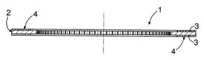
図1,2において,湿式クラッチ用摩擦板1は,金属製環状芯板2と,その環状芯板2の少なくとも一方の環状平面3,実施例では両環状平面3にそれぞれ接合された,繊維成分,添加成分,バインダ等よりなる摩擦材4とを有する。各摩擦材4は,環状平面3に配置された複数の摩擦材セグメント,実施例では1つの三角形状摩擦材セグメントaと,その傍から図1,時計回りに並ぶ5つの方形状摩擦材セグメントbを1組のセグメント群Gとして10組のセグメント群Gよりなり,相隣る両摩擦材セグメントa,b;b,b間にはオイル溝5が存する。
【0011】
各摩擦材4の製造に当っては,環状芯板2の一方の環状平面3に,複数の摩擦材セグメントa,b,つまり1組のセグメント群Gを同時に接合し,次いで,同様の接合作業を9回繰返すものである。
【0012】
次に,摩擦板1の製造について詳細に説明する。
【0013】
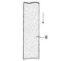
(a)摩擦材ロール(図示せず)から,図3に示すように1つの帯状摩擦材6を繰出す。その際,帯状摩擦材6の先端縁を芯板2の外周縁にほぼ合致するように円弧状に形成しておく。
【0014】
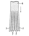
(b)複数,実施例では5つのスリッタを並列させた切断機(図示せず)を用いて,図4に示すように,帯状摩擦材6に,その長手方向に沿う5つの連続的な切込みを入れて6つの短冊状摩擦材7を形成する。切断機はスリッタに限定されない。
【0015】
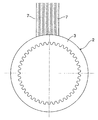
(c)図5に示すように,それら短冊状摩擦材7を,間隔規定部材8の6つの通し孔9にそれぞれ通して間を広げ,相隣る両短冊状摩擦材7間にオイル溝5に対応する間隔を形成してその状態を保持する。
【0016】
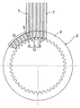
(d)図6に示すように,6つの短冊状摩擦材7の先端がターンテーブル(図示せず)上に設置された環状芯板2の外周面近傍に達したとき,それら短冊状摩擦材7の移動を停止させる。
【0017】
(e)図7に示すように,それら短冊状摩擦材7のうち,一方の端,つまり図7において左端に位置するものの先端部の一部分を,切断機(図示せず)の切断刃によって,環状平面3における方形状摩擦材セグメントbとの間にオイル溝5を確保すべく,全幅(幅:芯板2の周方向長さ)に亘って斜めに切除する。これにより台形状スクラップ10が生じる。
【0018】
(f)図8に示すように,芯板2の接着剤を塗布された環状平面3に,6つの短冊状摩擦材7の先端部を形成している,切除による1つの摩擦材セグメント対応部7aおよび原形の5つの摩擦材セグメント対応部7bを重ね合せる。
【0019】
(g)切断機(図示せず)の押え部材により各摩擦材セグメント対応部7a,7bを押えると共に切断刃によって,図9に示すように,各短冊状摩擦材7に芯板2の外周縁に沿った切断加工を施して,各摩擦材セグメント対応部7a,7bを各短冊状摩擦材7の残部から切放し,これにより,前記切除による1つの三角形状摩擦材セグメントaと,原形であったことによる5つの方形状摩擦材セグメントbとよりなる1組目のセグメント群Gを得る。
【0020】
(h)図10に示すように芯板3を反時計方向に36°回転させる。
【0021】
(i)図11に示すように,図7の(e)工程と同様に,左端の短冊状摩擦材7の先端部の一部分を全幅に亘って斜めに切除する。
【0022】
(j)図12に示すように,図8の(f)工程と同様に,芯板2の,接着剤を塗布された環状平面3に6つの短冊状摩擦材7の摩擦材セグメント対応部7a,7bを重ね合せる。
【0023】
(k)図13に示すように,図9の(g)工程と同様に,押え部材により各摩擦材セグメント対応部7a,7bを押えると共に切断刃によって各短冊状摩擦材7に芯材2の外周縁に沿った切断加工を施して,1つの三角形状摩擦材セグメントaと5つの方形状摩擦材セグメントbとよりなる2組目のセグメント群Gを得る。
【0024】
以後,図10〜13の(h)〜(k)工程を8回繰返して一方の側の摩擦材4を形成し,引続き,同様の方法で他方の側の摩擦材4の形成を行う。
【0025】
前記のように短冊状摩擦材7形成のための切込み,オイル溝5確保のための切除および摩擦材セグメント対応部7a,7bの,短冊状摩擦材7残部からの切放しを,切断刃を用いて行うと,帯状摩擦材6から摩擦材セグメントa,bを製作するに当り,発生するスクラップ10を前記切除によるものに止め,これにより摩擦材セグメントa,bの製作における歩留りを向上させることができる。
【0026】
次に,他の実施例について説明する。
【0027】
図14に示した実施例は,各組のセグメント群Gにおいて,5つの方形状摩擦材セグメントbの幅(周方向長さ)を三角形状摩擦材セグメントaから離れるに従って広くなるようにしたものである。これは短冊状摩擦材7の幅を変更することによって達成される。
【0028】
図15に示した実施例は,各組のセグメント群Gにおいて,三角形状摩擦材セグメントaおよびそれに隣接する方形状摩擦材セグメントb間のオイル溝5の幅(周方向長さ)を最小とし,他のオイル溝5の幅を三角形状摩擦材セグメントaから離れるに従って広くなるようにしたものである。これは相隣る両短冊状摩擦材7間の間隔を変更することによって達成される。
【0029】
図16に示した参考例は,2つの短冊状摩擦材7を用い,それらの先端部の一部分,つまり外側の角部をそれぞれオイル溝5確保のために切除するようにしたもので,これにより2つの三角形状スクラップ10が生じる。この場合,2つの摩擦材セグメント対応部7bから得られた2つの方形状摩擦材セグメントbが1組のセグメント群Gを形成する。また両短冊状摩擦材7は,複数の短冊状摩擦材のうち両方の端に位置するものに該当する。
【0030】
図17に示した参考例は,摩擦材4を外周側半部4Aと内周側半部4Bとに分け,外周側半部4Aの形成を2つの短冊状摩擦材7を用い,また内周側半部4Bの形成を同様に2つの短冊状摩擦材7を用いて行い,その際,それらの先端部の一部分を,図16例の場合と同様にそれぞれオイル溝5確保のために切除するようにしたものである。ただし,内周側半部4Bの形成において,前記切除および各摩擦材セグメント対応部7bの前記切放しは,芯板2上にて切断刃を用いて行われる。
【0031】
図18に示した実施例は,三角形状摩擦材セグメントaを形成するための短冊状摩擦材7を除いた他の短冊状摩擦材7の形成に当り,波形の切込みを入れるようにしたもので,これにより三角形状摩擦材セグメントaの両側のオイル溝5を除く他のオイル溝5が蛇行形状となる。これらの蛇行形オイル溝5はオイルの排出を妨げるので,クラッチが切れ易くなって引摺り抵抗が減少する。この場合,1組のセグメント群Gは,1つの三角形状摩擦材セグメント9と,2つの,一側面がS字状に湾曲した変形摩擦材セグメントcと,3つのS字状をなす変形摩擦材セグメントdとよりなる。図中,7c,7dは摩擦材セグメント対応部である。
【0032】
図19に示した実施例は,各セグメント群Gにおいて,三角形状摩擦材セグメントaを除く他の変形摩擦材セグメントeを,半径方向内方に向かう面がV形凹面11を,また半径方向外方へ向かう面がV形凸面12をそれぞれ有するように矢羽形に形成したものである。このような矢羽形をなす変形摩擦材セグメントeは,そのV形凹面11によってオイルの排出を妨げるので,クラッチの引摺り抵抗が減少する。図中,7eは摩擦材セグメント対応部である。
【0033】
図20に示した実施例は,材質を異にする二種の帯状摩擦材6,13より形成された二種の短冊状摩擦材7,14を用い,各環状平面3において一種の三角形状および方形状摩擦材セグメントa,bと他種の方形状摩擦材セグメントfとを交互に配置するようにしたものである。このような摩擦板1は,例えば特開平2−3716号公報に開示された湿式クラッチにおいて需要がある。図中,14fは摩擦材セグメント対応部を示す。
【0034】
図21に示した実施例は,図1〜13に示した実施例の変形例に該当する。即ち,6つの短冊状摩擦材7より1組の集合体Aを構成すると共に10組の集合体Aにおける摩擦材セグメント対応部7a,7bを芯板2の一方の環状平面3上に均等に配置し,10組のセグメント群Gを同時に接合して1回の接合作業で一方の摩擦材4を形成するようにしたものである。このような手段を採用すると,セグメント群Gの位置精度を容易に向上させることができる。
【0035】
なお,本発明における摩擦板1には芯板2の一方の環状平面3のみに摩擦材4を設けたものも含まれる。
【0036】
【発明の効果】
本発明によれば前記のような手段を採用することによって,摩擦材セグメントの製作における歩留りを向上させ,またオイル溝の幅および形状の自由度を高め得る,生産性の良い前記湿式クラッチ用摩擦板の製造方法を提供することができる。
【図面の簡単な説明】
【図1】摩擦板の平面図である
【図2】図1の2−2線断面図である。
【図3】帯状摩擦材の要部平面図である。
【図4】帯状摩擦材から複数の短冊状摩擦材を形成した状態を示す平面図である。
【図5】複数の短冊状摩擦材と間隔規定部材との関係を示す平面図である。
【図6】芯板と複数の短冊状摩擦材との関係を示す平面図である。
【図7】1つの短冊状摩擦材の先端部の一部分を切除した状態を示す平面図である。
【図8】複数の短冊状摩擦材の摩擦材セグメント対応部を芯板に重ね合せた状態を示す平面図である。
【図9】各摩擦材セグメント対応部を各短冊状摩擦材の残部から切放した状態を示す平面図である。
【図10】芯板を36°回転させた状態を示す平面図である。
【図11】1つの短冊状摩擦部材の先端部の一部分を切除した状態を示す平面図である。
【図12】複数の短冊状摩擦材の摩擦材セグメント対応部を芯板に重ね合せた状態を示す平面図である。
【図13】各摩擦材セグメント対応部を各短冊状摩擦材の残部から切放した状態を示す平面図である。
【図14】複数の摩擦材セグメントの幅を変更する場合において,複数の短冊状摩擦材の摩擦材セグメント対応部を芯板に重ね合せた状態を示す平面図である。
【図15】オイル溝の幅を変更する場合において,複数の短冊状摩擦材の摩擦材セグメント対応部を芯板に重ね合せた状態を示す平面図である。
【図16】2つの短冊状摩擦材を用いる場合において,それら短冊状摩擦材の先端部の一部分を切除した状態を示す平面図である。
【図17】2つの短冊状摩擦材を1組とし,それを2組用いる場合において,それら短冊状摩擦材の先端部の一部分を切除した状態を示す平面図である。
【図18】複数の波形切込み入り短冊状摩擦材を用いる場合において,それらの摩擦セグメント対応部を芯板に重ね合せた状態を示す平面図である。
【図19】複数の短冊状摩擦材の摩擦材セグメント対応部を芯板に重ね合せて,複数の矢羽形の変形摩擦材セグメントを有するセグメント群を形成した状態を示す平面図である。
【図20】材質を異にする二種の帯状摩擦材を用いる場合において,二種の,複数の短冊状摩擦材の摩擦材セグメント対応部を交互に芯板に重ね合せた状態を示す平面図である。
【図21】1回の接合作業で一方の摩擦材を形成する場合において,複数の短冊状摩擦材よりなる複数組の集合体の摩擦材セグメント対応部を芯板に重ね合せた状態を示す平面図である。
【符号の説明】
1…………摩擦板
2…………芯板
3…………環状平面
4…………摩擦材
5…………オイル溝
6…………帯状摩擦材
7…………短冊状摩擦材
7a,7b,7c,7d,7e,14f……摩擦材セグメント対応部
13………帯状摩擦材
14………短冊状摩擦材
a…………三角形状摩擦材セグメント
b,f………方形状摩擦材セグメント
c,d,e………変形摩擦材セグメント[0001]
BACKGROUND OF THE INVENTION
The present invention relates to a method for manufacturing a friction plate for a wet clutch.
[0002]
[Prior art]
Conventionally, this type of friction plate has an annular core plate and friction materials joined to both annular planes of the annular core plate, and each friction material has a plurality of friction material segments arranged on the annular plane. It is known that there is an oil groove between adjacent friction material segments.
[0003]
In this case, when joining the plurality of friction material segments to the annular flat surface of the annular core plate, the belt-shaped friction material is punched to form a friction material segment. A method of joining sheets is adopted (for example, refer to Patent Document 1 and Patent Document 2).
[0004]
[Patent Document 1]
JP-A-7-151175 [0023], FIGS.
[Patent Document 2]
JP-A-6-300051 gazette
[Problems to be solved by the invention]
However, according to the conventional method, there is a problem that the yield is low and uneconomical in the production of the friction segment.
[0006]
[Means for Solving the Problems]
It is an object of the present invention to provide a method for manufacturing a friction plate for a wet clutch with good productivity, which can improve the yield in manufacturing a friction material segment and can increase the degree of freedom of the width and shape of an oil groove. .
[0007]
In order to achieve the above object, according to the present invention, an annular core plate and a friction material joined to at least one annular plane of the annular core plate are provided. In order to manufacture a friction plate for a wet clutch that includes an oil groove between adjacent friction material segments, a plurality of the friction material segments are simultaneously joined to the annular flat surface of the annular core plate. In doing so, a process of forming a plurality of strip-shaped friction materials by making a plurality of continuous cuts along the longitudinal direction of at least one belt-shaped friction material, and widening between the strip-shaped friction materials, a step of holding the state to form a phase Tonariru interval corresponding to the oil groove between the two strips friction material, among which a strip of friction material, a portion of the distal end portion of which the edge of the hand , In the annular plane The step of cutting to secure the oil groove between the friction material segments and the annular flat surface coated with the adhesive of the core plate are formed with a plurality of tip end portions of the strip-shaped friction material. There is provided a method of manufacturing a friction plate for a wet clutch using a step of superposing friction material segment corresponding portions and cutting each friction material segment corresponding portion from the remainder of each strip-shaped friction material.
[0008]
When the above-mentioned means are adopted, cutting for forming the strip-shaped friction material, cutting for securing the oil groove, and cutting off the friction material segment corresponding part from the remaining strip-shaped friction material using the cutting blade respectively. Thus, when the friction material segment is manufactured from the belt-shaped friction material, the generated scrap can be stopped by the cutting and the yield in manufacturing the friction material segment can be improved.
[0009]
In addition, it is possible to change the width of the oil groove freely by changing the distance between adjacent strip-shaped friction materials, and the shape of the oil groove is also changed when the strip-shaped friction material is formed. In addition, since a plurality of friction material segments are simultaneously bonded to the core plate, it is effective in improving the productivity of the friction plate.
[0010]
DETAILED DESCRIPTION OF THE INVENTION
1 and 2, the wet clutch friction plate 1 includes a fiber
[0011]
In manufacturing each
[0012]
Next, the production of the friction plate 1 will be described in detail.
[0013]
(A) One belt-
[0014]
(B) Using a cutting machine (not shown) in which a plurality of, in the embodiment, five slitters are arranged in parallel, as shown in FIG. 4, five continuous cuts along the longitudinal direction of the belt-
[0015]
(C) As shown in FIG. 5, these strip-
[0016]
(D) As shown in FIG. 6, when the tips of the six strip-
[0017]
(E) As shown in FIG. 7, of those
[0018]
(F) As shown in FIG. 8, one friction material segment-corresponding portion by cutting, in which the tip portions of six strip-
[0019]
(G) The friction material segment
[0020]
(H) The
[0021]
(I) As shown in FIG. 11, as in the step (e) of FIG. 7, a part of the front end portion of the strip-shaped
[0022]
(J) As shown in FIG. 12, as in the step (f) of FIG. 8, the friction material
[0023]
(K) As shown in FIG. 13, as in the step (g) of FIG. 9, the friction material
[0024]
Thereafter, the steps (h) to (k) of FIGS. 10 to 13 are repeated eight times to form the
[0025]
Using the cutting blade, the cutting for forming the strip-shaped
[0026]
Next, another embodiment will be described.
[0027]
In the embodiment shown in FIG. 14, in each group of segments G, the width (circumferential length) of the five rectangular friction material segments b is increased as the distance from the triangular friction material segment a increases. is there. This is achieved by changing the width of the strip-shaped
[0028]
The embodiment shown in FIG. 15 minimizes the width (circumferential length) of the
[0029]
In the reference example shown in FIG. 16, two strip-shaped
[0030]
In the reference example shown in FIG. 17, the
[0031]
In the embodiment shown in FIG. 18, a corrugated cut is made in forming the other strip-shaped
[0032]
In the embodiment shown in FIG. 19, in each segment group G, the deformed friction material segment e other than the triangular friction material segment a is changed, the radially inward surface is the V-shaped
[0033]
The embodiment shown in FIG. 20 uses two kinds of strip-
[0034]
The embodiment shown in FIG. 21 corresponds to a modification of the embodiment shown in FIGS. That is, a set of aggregates A is composed of six strip-shaped
[0035]
The friction plate 1 in the present invention includes one in which the
[0036]
【The invention's effect】
According to the present invention, by adopting the above-mentioned means, the yield in the production of the friction material segment can be improved, and the oil groove width and shape flexibility can be increased. A method for manufacturing a plate can be provided.
[Brief description of the drawings]
FIG. 1 is a plan view of a friction plate. FIG. 2 is a sectional view taken along line 2-2 of FIG.
FIG. 3 is a plan view of an essential part of a belt-shaped friction material.
FIG. 4 is a plan view showing a state in which a plurality of strip-shaped friction materials are formed from a belt-shaped friction material.
FIG. 5 is a plan view showing a relationship between a plurality of strip-shaped friction materials and a spacing defining member.
FIG. 6 is a plan view showing the relationship between a core plate and a plurality of strip-shaped friction materials.
FIG. 7 is a plan view showing a state in which a part of the tip portion of one strip-shaped friction material is cut away.
FIG. 8 is a plan view showing a state in which the friction material segment corresponding portions of a plurality of strip-shaped friction materials are superposed on the core plate.
FIG. 9 is a plan view showing a state in which each friction material segment corresponding portion is cut off from the remaining portion of each strip-shaped friction material.
FIG. 10 is a plan view showing a state where a core plate is rotated by 36 °.
FIG. 11 is a plan view showing a state in which a part of the front end portion of one strip-shaped friction member is cut off.
FIG. 12 is a plan view showing a state in which the friction material segment corresponding portions of a plurality of strip-shaped friction materials are superposed on the core plate.
FIG. 13 is a plan view showing a state in which each friction material segment corresponding portion is cut off from the remaining portion of each strip-shaped friction material.
FIG. 14 is a plan view showing a state in which the friction material segment corresponding portions of a plurality of strip-shaped friction materials are superposed on the core plate when the widths of the plurality of friction material segments are changed.
FIG. 15 is a plan view showing a state in which the friction material segment corresponding portions of a plurality of strip-shaped friction materials are superposed on the core plate when the width of the oil groove is changed.
FIG. 16 is a plan view showing a state in which a part of the front end portion of the strip-shaped friction material is cut off when two strip-shaped friction materials are used.
FIG. 17 is a plan view showing a state in which a part of the front end portion of the strip-shaped friction material is cut off when two strip-shaped friction materials are used as one set and two sets are used.
FIG. 18 is a plan view showing a state in which a plurality of corrugated slit-like friction materials are used, and the friction segment corresponding portions are superposed on the core plate.
FIG. 19 is a plan view showing a state in which a segment group having a plurality of arrow-shaped deformed friction material segments is formed by superimposing friction material segment corresponding portions of a plurality of strip-shaped friction materials on a core plate.
FIG. 20 is a plan view showing a state in which the friction material segment corresponding portions of two or more strip-shaped friction materials are alternately superimposed on the core plate when two types of belt-shaped friction materials of different materials are used. It is.
FIG. 21 is a plan view showing a state in which the friction material segment corresponding portions of a plurality of sets of a plurality of strip-shaped friction materials are superimposed on the core plate when one friction material is formed by one joining operation. FIG.
[Explanation of symbols]
1 …………
Claims (1)
Priority Applications (3)
| Application Number | Priority Date | Filing Date | Title |
|---|---|---|---|
| JP2002365712A JP3971696B2 (en) | 2002-12-17 | 2002-12-17 | Method for manufacturing friction plate for wet clutch |
| US10/736,891 US6899783B2 (en) | 2002-12-17 | 2003-12-17 | Method of manufacturing friction plate for wet clutch |
| DE10359301A DE10359301B4 (en) | 2002-12-17 | 2003-12-17 | Method for producing a friction disk for a wet clutch |
Applications Claiming Priority (1)
| Application Number | Priority Date | Filing Date | Title |
|---|---|---|---|
| JP2002365712A JP3971696B2 (en) | 2002-12-17 | 2002-12-17 | Method for manufacturing friction plate for wet clutch |
Related Child Applications (1)
| Application Number | Title | Priority Date | Filing Date |
|---|---|---|---|
| JP2007085782A Division JP4523616B2 (en) | 2007-03-28 | 2007-03-28 | Friction plate for wet clutch and manufacturing method thereof |
Publications (3)
| Publication Number | Publication Date |
|---|---|
| JP2004197808A JP2004197808A (en) | 2004-07-15 |
| JP2004197808A5 JP2004197808A5 (en) | 2005-05-19 |
| JP3971696B2 true JP3971696B2 (en) | 2007-09-05 |
Family
ID=32588273
Family Applications (1)
| Application Number | Title | Priority Date | Filing Date |
|---|---|---|---|
| JP2002365712A Expired - Lifetime JP3971696B2 (en) | 2002-12-17 | 2002-12-17 | Method for manufacturing friction plate for wet clutch |
Country Status (3)
| Country | Link |
|---|---|
| US (1) | US6899783B2 (en) |
| JP (1) | JP3971696B2 (en) |
| DE (1) | DE10359301B4 (en) |
Families Citing this family (17)
| Publication number | Priority date | Publication date | Assignee | Title |
|---|---|---|---|---|
| WO2005085667A1 (en) * | 2004-03-04 | 2005-09-15 | Kabushiki Kaisha F.C.C. | Wet type clutch friction plate |
| JP4503416B2 (en) * | 2004-10-28 | 2010-07-14 | Nskワーナー株式会社 | Method for manufacturing wet friction plate |
| JP2008138821A (en) * | 2006-12-05 | 2008-06-19 | Aisin Chem Co Ltd | Multi-disk frictional engagement device |
| US20090071766A1 (en) * | 2007-09-13 | 2009-03-19 | Akebono Corporation (North America) | Brake pad assembly with wide slots for the reduction of noise |
| WO2009105861A1 (en) * | 2008-02-28 | 2009-09-03 | Magna Powertrain Inc. | Friction clutch and method to reduce drag loss in friction clutch |
| DE102009032180A1 (en) * | 2009-07-07 | 2011-01-13 | Hoerbiger Antriebstechnik Gmbh | Method for manufacturing friction disk, involves providing elongated metal strip with teeth at longitudinal edge and applying friction lining body or a sinter body on metal strip |
| DE102011109452A1 (en) * | 2011-08-04 | 2013-02-07 | Borgwarner Inc. | Reiblamette with a Papierreibbelag, method for producing such a friction plate and wet-running multi-plate clutch or brake with such a friction plate |
| JP5782955B2 (en) * | 2011-09-22 | 2015-09-24 | トヨタ紡織株式会社 | Manufacturing method of core of rotating electrical machine |
| US9360053B2 (en) * | 2011-11-16 | 2016-06-07 | GM Global Technology Operations LLC | Friction plate for a friction clutch pack |
| DE102013010651A1 (en) * | 2013-06-26 | 2014-12-31 | Daimler Ag | Wet clutch device for a motor vehicle |
| US10125836B2 (en) * | 2015-06-10 | 2018-11-13 | Nucap Industries Inc. | Brake pad with preformed multi-layer friction pad and shim |
| JP6254654B1 (en) * | 2016-09-08 | 2017-12-27 | アイシン化工株式会社 | Wet friction material |
| AT518883B1 (en) | 2016-09-27 | 2018-02-15 | Miba Frictec Gmbh | friction plate |
| US10850352B2 (en) | 2017-12-21 | 2020-12-01 | GM Global Technology Operations LLC | Method of laser cutting grooves in a friction clutch plate |
| JP7219673B2 (en) * | 2019-05-22 | 2023-02-08 | 株式会社エフ・シー・シー | Wet friction plate and wet multi-plate clutch device |
| USD951064S1 (en) * | 2019-09-20 | 2022-05-10 | Caterpillar Inc. | Spacer |
| CN113510180B (en) * | 2020-04-10 | 2023-02-07 | 中国兵器工业第五九研究所 | Fine blanking forming device and friction plate fine blanking forming method |
Family Cites Families (14)
| Publication number | Priority date | Publication date | Assignee | Title |
|---|---|---|---|---|
| US4260074A (en) * | 1979-11-09 | 1981-04-07 | Vending Components Inc. | Method and apparatus for dispensing beer through a gas line |
| US4878282A (en) | 1987-09-04 | 1989-11-07 | Borg-Warner Automotive Gmbh | Method for the production of friction plates, synchronizing blocker rings or similar structures |
| US5094331A (en) * | 1988-03-18 | 1992-03-10 | Honda Giken Kogyo Kabushiki Kaisha | Wet-type multiplate clutch |
| JPH023716A (en) | 1988-06-13 | 1990-01-09 | Honda Motor Co Ltd | Humid type frictional member and humid type frictional engagement device for speed change gear |
| US5571372A (en) * | 1992-07-21 | 1996-11-05 | Kabushiki Kaisha F.C.C. | Process and apparatus for manufacturing clutch friction plate |
| US5460255A (en) | 1993-03-25 | 1995-10-24 | Borg-Warner Automotive, Inc. | Universal segmented friction clutch facing |
| US5454454A (en) | 1993-11-22 | 1995-10-03 | Raybestos Products Co. | Polygonal friction disk and method |
| JPH07151175A (en) | 1993-11-29 | 1995-06-13 | Akebono Brake Ind Co Ltd | Method and device for manufacturing friction disc |
| US5776288A (en) * | 1996-05-07 | 1998-07-07 | Automotive Composites Company | Method and apparatus for lined clutch plate |
| US5897737A (en) * | 1997-05-07 | 1999-04-27 | Borg-Warner Automotive, Inc. | Method for making a core plate having multiple friction material segments |
| JP4163283B2 (en) * | 1998-04-23 | 2008-10-08 | Nskワーナー株式会社 | Friction plate manufacturing method and apparatus |
| JP3643018B2 (en) * | 1999-07-22 | 2005-04-27 | アイシン化工株式会社 | Method and apparatus for manufacturing clutch friction plate |
| JP3614763B2 (en) * | 2000-08-02 | 2005-01-26 | 株式会社エフ・シー・シー | Manufacturing method of friction plate having flat friction surface and manufacturing apparatus thereof |
| US6601684B2 (en) * | 2001-09-12 | 2003-08-05 | Borgwarner Inc. | Unitary, circumferentially edge wound friction material clutch plate, and method of making same |
-
2002
- 2002-12-17 JP JP2002365712A patent/JP3971696B2/en not_active Expired - Lifetime
-
2003
- 2003-12-17 DE DE10359301A patent/DE10359301B4/en not_active Expired - Fee Related
- 2003-12-17 US US10/736,891 patent/US6899783B2/en not_active Expired - Lifetime
Also Published As
| Publication number | Publication date |
|---|---|
| DE10359301A1 (en) | 2004-07-15 |
| JP2004197808A (en) | 2004-07-15 |
| DE10359301B4 (en) | 2008-02-28 |
| US6899783B2 (en) | 2005-05-31 |
| US20040154735A1 (en) | 2004-08-12 |
Similar Documents
| Publication | Publication Date | Title |
|---|---|---|
| JP3971696B2 (en) | Method for manufacturing friction plate for wet clutch | |
| JP2004197808A5 (en) | ||
| JP5233015B1 (en) | Cutting tool | |
| US2589168A (en) | Patch reinforcement | |
| JP4523616B2 (en) | Friction plate for wet clutch and manufacturing method thereof | |
| CN111108311B (en) | Sealing strip for processing as continuous strip | |
| EP1574733B1 (en) | Method of manufacturing friction plate for wet clutch | |
| CA2460681C (en) | Method of manufacturing friction plate for wet clutch | |
| JP6755267B2 (en) | Die-cut tab blanket for counter dies of rotary die-cutting equipment | |
| JP5186467B2 (en) | Rotating electric machine stator core | |
| JP2009119825A (en) | Pneumatic radial tire which acted code member for tire reinforcement, its manufacturing process, and the code member for tire reinforcement | |
| JP6447365B2 (en) | Iron core manufacturing equipment | |
| JP4868346B2 (en) | Cutter roller, method for producing long film with cut and method for producing bag with cut | |
| JP3848343B2 (en) | Corrugated paper and method for producing corrugated paper | |
| JP2004025311A (en) | Ruled line forming apparatus | |
| JP5614169B2 (en) | Perforation processing equipment | |
| JPH0972364A (en) | Wet-type friction material | |
| JPS6280316A (en) | Clutch facing device | |
| JP3433159B2 (en) | Circular saw | |
| JP2648832B2 (en) | Rubber foot forming sheet | |
| JP3723438B2 (en) | Annular cutter | |
| JP2010046986A (en) | Tire manufacturing method | |
| EP2391835B1 (en) | Brake disk and associated method of production | |
| JP2010242946A (en) | Transmission belt | |
| TWI583341B (en) | Dust drum device and manufacturing method thereof |
Legal Events
| Date | Code | Title | Description |
|---|---|---|---|
| A621 | Written request for application examination |
Free format text: JAPANESE INTERMEDIATE CODE: A621 Effective date: 20040630 |
|
| A521 | Request for written amendment filed |
Free format text: JAPANESE INTERMEDIATE CODE: A523 Effective date: 20040705 |
|
| A977 | Report on retrieval |
Free format text: JAPANESE INTERMEDIATE CODE: A971007 Effective date: 20060526 |
|
| A131 | Notification of reasons for refusal |
Free format text: JAPANESE INTERMEDIATE CODE: A131 Effective date: 20060913 |
|
| A521 | Request for written amendment filed |
Free format text: JAPANESE INTERMEDIATE CODE: A523 Effective date: 20061113 |
|
| A131 | Notification of reasons for refusal |
Free format text: JAPANESE INTERMEDIATE CODE: A131 Effective date: 20070131 |
|
| A521 | Request for written amendment filed |
Free format text: JAPANESE INTERMEDIATE CODE: A523 Effective date: 20070328 |
|
| TRDD | Decision of grant or rejection written | ||
| A01 | Written decision to grant a patent or to grant a registration (utility model) |
Free format text: JAPANESE INTERMEDIATE CODE: A01 Effective date: 20070523 |
|
| A61 | First payment of annual fees (during grant procedure) |
Free format text: JAPANESE INTERMEDIATE CODE: A61 Effective date: 20070608 |
|
| R150 | Certificate of patent or registration of utility model |
Free format text: JAPANESE INTERMEDIATE CODE: R150 Ref document number: 3971696 Country of ref document: JP Free format text: JAPANESE INTERMEDIATE CODE: R150 |
|
| FPAY | Renewal fee payment (event date is renewal date of database) |
Free format text: PAYMENT UNTIL: 20110615 Year of fee payment: 4 |
|
| R250 | Receipt of annual fees |
Free format text: JAPANESE INTERMEDIATE CODE: R250 |
|
| R250 | Receipt of annual fees |
Free format text: JAPANESE INTERMEDIATE CODE: R250 |
|
| FPAY | Renewal fee payment (event date is renewal date of database) |
Free format text: PAYMENT UNTIL: 20120615 Year of fee payment: 5 |
|
| FPAY | Renewal fee payment (event date is renewal date of database) |
Free format text: PAYMENT UNTIL: 20130615 Year of fee payment: 6 |
|
| R250 | Receipt of annual fees |
Free format text: JAPANESE INTERMEDIATE CODE: R250 |
|
| FPAY | Renewal fee payment (event date is renewal date of database) |
Free format text: PAYMENT UNTIL: 20130615 Year of fee payment: 6 |
|
| FPAY | Renewal fee payment (event date is renewal date of database) |
Free format text: PAYMENT UNTIL: 20140615 Year of fee payment: 7 |
|
| R250 | Receipt of annual fees |
Free format text: JAPANESE INTERMEDIATE CODE: R250 |
|
| R250 | Receipt of annual fees |
Free format text: JAPANESE INTERMEDIATE CODE: R250 |
|
| R250 | Receipt of annual fees |
Free format text: JAPANESE INTERMEDIATE CODE: R250 |
|
| R250 | Receipt of annual fees |
Free format text: JAPANESE INTERMEDIATE CODE: R250 |
|
| R250 | Receipt of annual fees |
Free format text: JAPANESE INTERMEDIATE CODE: R250 |
|
| R250 | Receipt of annual fees |
Free format text: JAPANESE INTERMEDIATE CODE: R250 |
|
| R250 | Receipt of annual fees |
Free format text: JAPANESE INTERMEDIATE CODE: R250 |
|
| EXPY | Cancellation because of completion of term |