JP3969873B2 - Toner and image forming method using the toner - Google Patents
Toner and image forming method using the toner Download PDFInfo
- Publication number
- JP3969873B2 JP3969873B2 JP36368298A JP36368298A JP3969873B2 JP 3969873 B2 JP3969873 B2 JP 3969873B2 JP 36368298 A JP36368298 A JP 36368298A JP 36368298 A JP36368298 A JP 36368298A JP 3969873 B2 JP3969873 B2 JP 3969873B2
- Authority
- JP
- Japan
- Prior art keywords
- toner
- toner particles
- image
- image forming
- weight
- Prior art date
- Legal status (The legal status is an assumption and is not a legal conclusion. Google has not performed a legal analysis and makes no representation as to the accuracy of the status listed.)
- Expired - Fee Related
Links
Images


Classifications
-
- G—PHYSICS
- G03—PHOTOGRAPHY; CINEMATOGRAPHY; ANALOGOUS TECHNIQUES USING WAVES OTHER THAN OPTICAL WAVES; ELECTROGRAPHY; HOLOGRAPHY
- G03G—ELECTROGRAPHY; ELECTROPHOTOGRAPHY; MAGNETOGRAPHY
- G03G9/00—Developers
- G03G9/08—Developers with toner particles
- G03G9/0821—Developers with toner particles characterised by physical parameters
-
- G—PHYSICS
- G03—PHOTOGRAPHY; CINEMATOGRAPHY; ANALOGOUS TECHNIQUES USING WAVES OTHER THAN OPTICAL WAVES; ELECTROGRAPHY; HOLOGRAPHY
- G03G—ELECTROGRAPHY; ELECTROPHOTOGRAPHY; MAGNETOGRAPHY
- G03G9/00—Developers
- G03G9/08—Developers with toner particles
- G03G9/0825—Developers with toner particles characterised by their structure; characterised by non-homogenuous distribution of components
-
- G—PHYSICS
- G03—PHOTOGRAPHY; CINEMATOGRAPHY; ANALOGOUS TECHNIQUES USING WAVES OTHER THAN OPTICAL WAVES; ELECTROGRAPHY; HOLOGRAPHY
- G03G—ELECTROGRAPHY; ELECTROPHOTOGRAPHY; MAGNETOGRAPHY
- G03G9/00—Developers
- G03G9/08—Developers with toner particles
- G03G9/0827—Developers with toner particles characterised by their shape, e.g. degree of sphericity
-
- G—PHYSICS
- G03—PHOTOGRAPHY; CINEMATOGRAPHY; ANALOGOUS TECHNIQUES USING WAVES OTHER THAN OPTICAL WAVES; ELECTROGRAPHY; HOLOGRAPHY
- G03G—ELECTROGRAPHY; ELECTROPHOTOGRAPHY; MAGNETOGRAPHY
- G03G9/00—Developers
- G03G9/08—Developers with toner particles
- G03G9/087—Binders for toner particles
-
- G—PHYSICS
- G03—PHOTOGRAPHY; CINEMATOGRAPHY; ANALOGOUS TECHNIQUES USING WAVES OTHER THAN OPTICAL WAVES; ELECTROGRAPHY; HOLOGRAPHY
- G03G—ELECTROGRAPHY; ELECTROPHOTOGRAPHY; MAGNETOGRAPHY
- G03G9/00—Developers
- G03G9/08—Developers with toner particles
- G03G9/087—Binders for toner particles
- G03G9/08775—Natural macromolecular compounds or derivatives thereof
- G03G9/08782—Waxes
Landscapes
- Physics & Mathematics (AREA)
- General Physics & Mathematics (AREA)
- Spectroscopy & Molecular Physics (AREA)
- Developing Agents For Electrophotography (AREA)
- Fixing For Electrophotography (AREA)
- Dry Development In Electrophotography (AREA)
- Electrostatic Charge, Transfer And Separation In Electrography (AREA)
Description
【0001】
【発明の属する技術分野】
本発明は、電子写真法、静電記録法、磁気記録法、トナージェット法などを利用した記録方法に用いられるトナー、及び、該トナーを用いた画像形成方法に関するものである。詳しくは、複写機、プリンター、ファクシミリ、プロッター等に利用し得る画像記録装置に用いられるトナー、及び、該トナーを用いた画像形成方法に関するものである。
【0002】
【従来の技術】
従来、電子写真法としては米国特許第2,297,691号明細書、特公昭42−23910号公報および特公昭43−24748号公報等に記載されている如く多数の方法が知られているが、一般には光導電性物質を利用し、種々の手段により感光体上に電気的潜像を形成し、次いで該潜像をトナーを用いて現像し、必要に応じて直接的あるいは間接的手段を用い、紙等の転写材にトナー画像を転写した後、加熱、加圧、あるいは溶剤蒸気などにより定着し複写物等を得るものであり、そして感光体上に転写せずに残った未転写トナーは種々の方法でクリーニングされ、上述の工程が繰り返される。
【0003】
また、一般的なフルカラー画像を形成する方法の一例について説明すると、感光体ドラムの感光体(静電潜像担持体)を一次帯電器によって均一に帯電し、原稿のマゼンタ画像信号にて変調されたレーザー光により画像露光を行い、感光体ドラム上に静電潜像を形成し、マゼンタトナーを保有するマゼンタ現像器により該静電潜像の現像を行い、マゼンタトナー画像を形成する。ついで搬送されてきた転写材に転写帯電器によって前記の感光体ドラムに現像されたマゼンタトナー画像を直接的、あるいは間接的手段を用い転写する。
【0004】
一方、前記の静電潜像の現像を行った後の感光体ドラムは、除電用帯電器により除電し、クリーニング手段によってクリーニングを行った後、再び一次帯電器によって帯電し、同様にシアントナー画像の形成及び前記のマゼンタトナー画像を転写した転写材へのシアントナー画像の形成を行い、更にイエロー色、ブラック色と順次同様に行って、4色のトナー画像を転写材に転写する。該4色のトナー画像を有する転写材を定着ローラにより熱及び圧力の作用で定着することによりフルカラー画像を形成する。
【0005】
近年このような装置は、単なるオリジナル原稿を複写するための事務処理用複写機というだけでなく、コンピューターの出力としてのレーザービームプリンター(LBP)、あるいは個人向けのパーソナルコピー(PC)という分野で使われ始めた。
【0006】
また、このようなLBPやPCに代表される分野以外にも、基本エンジンを応用した普通紙ファックスヘの展開も急激に発展を遂げつつある。
【0007】
そのため、より小型、より軽量そしてより高速、より高画質、より高信頼性が厳しく追及されてきており、機械は種々の点でよりシンプルな要素で構成されるようになってきている。その結果、トナーに要求される性能はより高度になり、トナーの性能向上が達成できなければ、より優れた機械が成り立たなくなってきている。また、近年多様な複写のニーズに伴い、カラー複写に対する需要も急増しており、オリジナルカラー画像をより忠実に複写するため、さらに一層の高画質、高解像度等が望まれている。さらに、両面のオリジナルカラー原稿の複写に対する要求も高まってきている。
【0008】
これらの観点より、該カラーの画像形成方法に使用されるトナーは、これに加熱した際の溶融性および混色性が良いことが必要であり、軟化点が低く、かつ溶融粘度の低いシャープメルト性の高いトナーを使用することが好ましい。
【0009】
すなわち、係るシャープメルトトナーを使用することにより、複写物の色再現範囲を広め、原稿像に忠実なカラーコピーを得ることができる。
【0010】
しかしながら、このようなシャープメルト性の高いカラートナーは、一般に定着ローラとの親和性が高く、定着時に定着ローラにオフセットしやすい傾向にある。
【0011】
特にカラー画像形成装置における定着装置の場合、転写材上にマゼンタ、シアン、イエロー、ブラックと複数層のトナー層が形成されるため、トナー層厚の増大から特にオフセットが発生しやすい傾向にある。
【0012】
従来定着ローラ表面にトナーを付着させない目的で、例えば、ローラ表面をシリコーンゴムやフッ素系樹脂などの、トナーに対して離型性に優れた材料で被覆し、さらにその表面にオフセット防止、および、ローラ表面の疲労を防止するためにシリコーンオイル、フッ素オイルのごとき離型性の高い液体の薄膜でローラ表面を被覆することが行われている。しかしながら、この方法はトナーのオフセットを防止する点では極めて有効であるが、オフセット防止用液体を供給するために装置が必要なため、定着装置が複雑になること等の問題を有していることはもちろんのこと、このオイル塗布が定着ローラを構成している層間の剥離を起こし結果的に定着ローラの短寿命化を促進するという弊害がつきまとう。
【0013】
そこで、シリコーンオイルの供給装置などを用いないで、かわりにトナー中から加熱時にオフセット防止液体を供給しようという考えから、トナー中に低分子量ポリエチレン、低分子量ポリプロピレンなどの離型剤を添加する方法が提案されている。
【0014】
トナー中に離型剤としてワックスを含有させることは、例えば特公昭52−3304号公報、特公昭52−3305号公報、特開昭57−52574号公報等に技術が開示されている。
【0015】
また、特開平3−50559号公報、特開平2−79860号公報、特開平1−109359号公報、特開昭62−14166号公報、特開昭61−273554号公報、特開昭61−94062号公報、特開昭61−138259号公報、特開昭60−252361号公報、特開昭60−252360号公報、特開昭60−217366号公報などにワックス類を含有させる技術が開示されている。
【0016】
ワックス類は、トナーの低温時や高温時の耐オフセット性の向上や、低温時の定着性の向上のために用いられているが、反面、耐ブロッキング性を悪化させたり、複写機等の機内昇温などによって熱にさらされたり、また長時間トナーを放置した際にワックスがトナー表面にマイグレーションして現像性が悪化したりする。
【0017】
こうした問題に対して、新規トナーの開発にかかる期待は大なるものであった。
【0018】
上記の課題に対して懸濁重合法トナーが提案されている(特公昭36−10231号公報)。この懸濁重合法においては重合性単量体および着色剤(さらに必要に応じて重合開始剤、架橋剤、荷電制御剤、その他の添加剤)を均一に溶解または分散せしめて単量体組成物とした後、この単量体組成物を分散安定剤を含有する連続相(例えば水相)中に適当な撹拌機を用いて分散し同時に重合反応を行わせ、所望の粒径を有するトナー粒子を得るものである。
【0019】
この懸濁重合法では、水のごとき極性の大なる分散媒中で単量体組成物の液滴を生成せしめるため、単量体組成物に含まれる極性基を有する成分は水相との界面である表層部に存在しやすく、非極性の成分は表層部に存在しないという、いわゆるコア/シェル構造を形成することができる。即ち、重合法によるトナーは、離型剤であるワックス成分の内包化により、低温定着性、耐ブロッキング性と耐久性、耐高温オフセット性という相反する性能を両立することが可能となり、かつ定着ローラにオイル等の離型剤を塗布することなく、高温オフセットを防止することが可能である。
【0020】
特開平6−194877号公報には、結着樹脂のマトリックス中に、結晶性の(メタ)アクリル酸エステルポリマーを複数のドメインとして形成させ、かつ、さらにこのドメイン中に結着樹脂が複数のドメインを形成して存在し、海−島−海構造を有するトナーが開示されている。該公報に従って重量平均分子量35000〜500000の比較的溶融粘度の高い結晶性ポリ(メタ)アクリル酸ベヘニルを高温オフセット防止剤として用いることにより、耐高温オフセット性の優れたトナーを得ることができる。しかし、使用する該結晶性ポリ(メタ)アクリル酸ベヘニルの溶融粘度が高すぎるために低温定着性が悪く、更なる改良が必要である。また、該高温オフセット防止剤は結晶性であるため、例えばOHPへプリントアウトした際の光透過性が悪くフルカラートナーへの適用は困難である。
【0021】
また海−島−海構造を有するトナーであっても、トナー中の残留モノマー量が多い場合には、長時間トナーを放置した際に、ワックス成分中の樹脂がワックスと相溶化してしまい、海−島−海構造がくずれるため、海−島−海構造を有することによる効果が十分に得られなくなったり、トナー粒子の機械的強度の低下が生じやすいものである。
【0022】
ところで、トナー粒子中には着色剤である各種の顔料、染料が必須成分として含まれているが、これらの着色剤は吸湿性を有しているものが多く、結果として環境安定性に問題を生じる場合がある。この問題に対する改善方法として、特開昭63−19663号公報には、表面に露出したカーボンブラックの量を抑制した球形トナーが、また、特開平5−289396号公報には、分散助剤の存在下熱可塑性のマトリクス樹脂中に着色剤が分散したドメイン樹脂を微細に分散させることにより、着色剤のトナー表面への露出を防止したイエロー、マゼンタ、シアンの各着色剤を含有するフルカラー用トナーが開示されている。これらの公報に従えば、吸湿性を有する着色剤のトナー表面への露出を抑制することで、環境湿度によらず帯電特性が安定したトナーを得ることができる。しかし、特開昭63−19663号公報に記載されているトナーの場合には画像の黒色度が不充分であり、また、特開平5−289396号公報に記載されているトナーの場合には、十分な低温定着性を有しているとは言い難い。
【0023】
従来、フルカラー複写機においては、4つの感光体とベルト状転写ベルトを用い、各感光体上に形成された静電潜像をシアン、マゼンタ、イエローおよびブラックトナーを用いて現像後、感光体とベルト転写体間に転写材を搬送しストレートパス間で転写後、フルカラー画像を形成せしめる方法や、感光体に対向せしめた転写体表面に静電気力やグリッパー等の機械的作用により転写材を巻き付け、現像−転写工程を4回実施することで結果的にフルカラー画像を得る方法等が一般的に利用されている。
【0024】
また、近年フルカラー用複写材として通常の紙やオーバーヘッドプロジェクター用フィルム(OHP)以外に厚紙やカード、葉書等小サイズ紙等への多様なマテリアル展開の必要性が増してきている。上記の4つの感光体を用いる方法においては、転写材がストレートに搬送するため多様な転写材への適用範囲は広いが、複数のトナー像を正確に所定の転写材の位置に重ね合わせる必要があり、少しのレジストレーションの相違によっても高画質の画像を再現性よく得ることが困難で、転写材の搬送機構が複雑化し、信頼性の低下、部品点数の増加を招くという問題がある。また、転写材を転写体表面に吸着させ巻き付ける方法で秤量の大きな厚紙を用いる際においては、転写材のコシの強さで転写材の後端が密着不良を起こし、結果的に転写に基づく画像欠陥を起こし好ましくない。小サイズ紙に対しても同様に画像欠陥が発生する場合がある。
【0025】
ドラム形状の中間転写体を用いるフルカラー画像装置は、米国特許第5,187,526号明細書や特開平4−16426号公報等で既に知られている。米国特許第5,187,526号明細書においては、ポリウレタンを基材とする表層からなる中間転写ローラの体積固有抵抗値が、109Ω・cm未満であり、同様の表面層から構成された転写ローラの体積固有抵抗値が、1010Ω・cm以上とすることで高画質を得ることができると記載されている。しかしながら、この様な系においては、転写材へのトナーの転写時に充分なトナーヘの転写電荷量を与えるためには、高出力電界が必要となるため導電性付与材を分散せしめたポリウレタンから構成された表層が、局所的にブレイクダウンを起こし、トナー乗り量の少ないハーフトーン画像において顕著な画像乱れが発生し好ましくない。さらにこの様な高電圧の印加は、相対湿度が60%RHを上回る高湿度下の環境においては、転写材の低抵抗化に伴い転写電流が漏洩して転写不良を起こしやすく、一方、相対湿度が40%RH以下の低湿度環境下においても転写材の不均一抵抗ムラに基づく転写不良の原因となる場合がある。
【0026】
中間転写体を用いる構成とトナーとの関係を記載しているものとして、特開昭59−15739号公報および特開昭59−5046号公報がある。しかしながら、該公報においては、粘着性の中間転写体を用い10μm以下のトナーを効率よく転写せしめることしか述べられていない。通常中間転写体を用いる系においては、トナーの顕色像を感光体から中間転写体に一旦転写後、さらに中間転写体から転写材上に再度転写することが必要であり、従来の上記方法と比ベトナーの転写効率を従来以上に高める必要がある。特に複数のトナー像を現像後転写せしめるフルカラー複写機を用いた場合においては、白黒複写機に用いられる一色の黒トナーの場合と比較し感光体上のトナー量が増加し、単に従来のトナーを用いただけでは転写効率を向上させることが困難である。さらに通常のトナーを用いた場合には、感光体や中間転写体とクリーニング部材との間、および/または、感光体と中間転写体間でのズリ力や摺擦力のために感光体表面や中間転写体表面にトナーの融着やフィルミング等が発生して転写効率の悪化や、フルカラーにおいては4色のトナー像が均一に転写されないことから色ムラやカラーバランスの面で問題が生じやすく、高画質のフルカラー画像を安定して出力することが困難であった。
【0027】
また、通常のフルカラー複写機に搭載されるトナーとしては、定着工程で各カラートナーが充分混色することが必要で、このことにより色再現性の向上やOHP画像の透明性が重要であり、黒トナーと比ベカラートナーは、一般的にシャープメルトで低分子量の樹脂を使用することが好ましい。また、通常の黒トナーには、定着時の耐高温オフセット性を向上させるためにポリエチレンワックスやポリプロピレンワックスに代表される比較的結晶性の高い離型剤が用いられている。しかしながら、フルカラートナーにおいては、この離型剤の結晶性のためOHPのトナー画像は、出力した際著しく透明性が阻害される。このため、通常カラートナー構成成分として離型剤を添加せずに加熱定着ローラヘシリコーンオイル等を均一塗布せしめることで、結果的に耐高温オフセット性の向上を図っている。しかしながら、この様にして得られたトナー定着像を有する転写材は、その表面に余分のシリコーンオイル等が付着しているため、ユーザーが使用する際不快感を生じ好ましくない。このように当接部分の多い中間転写体を用いたフルカラー画像形成には、現状困難な問題が多い。特開昭59−15739号公報および特開昭59−5046号公報には、この点に関するトナーまたは中間転写体への工夫は提案されていない。
【0028】
【発明が解決しようとする課題】
本発明の目的は、低温定着性および保存安定性が良好で、かつ、耐久性の優れたトナー、および該トナーを用いた画像形成方法を提供するものである。
【0029】
本発明の目的は、画像の色味が良好で、且つ、グロスが適性なトナー、および該トナーを用いた画像形成方法を提供するものである。
【0030】
【課題を解決するための手段および作用】
本発明は、結着樹脂、着色剤及びワックス成分を少なくとも含有するトナー粒子を有するトナーにおいて、
透過型電子顕微鏡(TEM)を用いて該トナー粒子の断層面を観察した時に、該ワックス成分が結着樹脂中において粒状に分散しており、且つ、該ワックス成分中において一部の結着樹脂が粒状に分散しており、
該トナー粒子中に含有されている残留モノマーの含有量が、トナー粒子の重量を基準として500ppm以下であることを特徴とするトナーに関する。
【0032】
さらに本発明は、外部より帯電部材に電圧を印加し、静電潜像担持体に帯電を行なう帯電工程;帯電された静電潜像担持体に静電荷像を形成する静電荷像形成工程;現像剤担持体に担持されたトナーで、該静電荷像を現像してトナー像を静電潜像担持体上に形成する現像工程;静電潜像担持体上の該トナー像を記録材に転写する転写工程;記録材上のトナー像を加熱定着する定着工程;を少なくとも有する画像形成方法において、
上述の本発明のトナーを用いることを特徴とする画像形成方法に関する。
【0033】
さらに本発明は、外部より帯電部材に電圧を印加し、静電潜像担持体に帯電を行なう帯電工程;帯電された静電潜像担持体に静電荷像を形成する静電荷像形成工程;現像剤担持体に担持されたトナーで、該静電荷像を現像してトナー像を静電潜像担持体上に形成する現像工程;静電潜像担持体上の該トナー像を中間転写体に転写する第1の転写工程;該中間転写体上のトナー像を記録材に転写する第2の転写工程;記録材上のトナー像を加熱定着する定着工程;を少なくとも有する画像形成方法において、
上述の本発明のトナーを用いることを特徴とする画像形成方法に関する。
【0034】
本発明者らは、鋭意検討の結果、結着樹脂中に粒状に分散しているワックス成分中に、更に樹脂成分を分散させて、海−島−海構造とし、且つ、トナー粒子中に含有させている不純物の量を500ppm以下とすることにより、極めて低温定着性及び保存安定性が良好で、かつ、耐久性の優れたトナーが得られることを見出し、本発明を完成するに至った。
【0036】
【発明の実施の形態】
本発明によるトナーは、少なくとも結着樹脂、着色剤及びワックス成分から構成されている。本発明にかかるトナーを透過型電子顕微鏡(TEM)を用いて断層面の観察を行なうと、ワックス成分が結着樹脂中において粒状に分散しており、且つ、樹脂成分が該ワックス成分中に分散しているという特徴がある。
【0037】
上記の如く、ワックス成分中に樹脂成分を分散させた特殊な構造とすることにより、定着時にワックス成分と共に該ワックス成分中に分散されていた樹脂成分が、周りに存在するワックス成分の影響を受けて速やかに溶融されて転写材に広がり、極めて低温定着性が良好なものとなる。海−島−海構造を有しているトナーは、樹脂成分とワックス成分との接触面積が特に大きくなるため、ワックス成分の影響が大きくなり、低温定着性が向上するものと思われる。また同時に、ワックス成分中に一部の結着樹脂が分散することにより、低温定着性を維持しつつトナー粒子全体の機械的強度が増し、トナーの劣化や画像形成装置への汚染を防止できるだけでなく、良好な帯電性が維持され、ドット再現性に優れたトナー画像を長期にわたって形成することが可能となる。
【0038】
更に本発明のトナーは、ワックス成分が、結着樹脂中に粒状に分散して内包されているため、優れた耐ブロッキング性を有しつつ、定着性や現像性に関しても優れたものである。
【0039】
本発明のトナーは、含有している残留モノマーの量がトナー粒子の重量基準で500ppm以下である。好ましくは200ppm以下であり、特に好ましくは100ppm以下である。トナー粒子に含有されている残留モノマーの量が500ppm以下であると、ワックス成分と該ワックス成分中に分散している樹脂成分とが相溶化することがなく、明確に相分離して存在するために、海−島−海構造の効果が顕著なものとなる。トナー粒子に含有される残留モノマーの量が、500ppmを超える場合には、ワックス成分と該ワックス成分中に分散している樹脂成分が相溶化してしまうため、トナー粒子の機械的強度が低下し、十分な耐久性が得られにくいという問題や、トナーの定着時にモノマー臭が発生し、使用者に不快感を与えるという問題、更にはトナーの帯電性や耐ブロッキング性に関しても問題が生じやすい。
【0040】
本発明において残留モノマーは、後述する結着樹脂の製造や直接重合法によりトナーを製造する際の未反応モノマーである。
【0041】
トナー中の残留モノマーを低減する方法としては、公知の方法を適用することが可能で、例えば結着樹脂の製造や直接重合法によりトナーを製造する際に開始剤の添加方法や反応温度をコントロールすることで残留モノマーを抑制したり、重合後に蒸留を行うことで残留モノマーを除去することができる。また、粉砕法によりトナーを製造する場合には、ニーダー等により原材料を加熱混練する際に減圧して除去したり、重合法によりトナーを製造する際にはスプレードライ等の利用により比較的効率良く残留モノマーを除去することができる。特に懸濁重合法によりトナーを製造する場合にはトナー粒子を加熱乾燥する際にも除去することが可能である。
【0042】
本発明において、トナー粒子中の残留モノマーの定量方法については、ガスクロマトグラフィー(GC)を用いる方法等の公知の方法を適用することができる。
【0043】
トナー中の残留モノマーをGCを用いて定量する場合の具体例を以下に記す。
【0044】
本発明において、「結着樹脂中にワックス成分が粒状に分散した状態」というのは、以下のように定義される。後述するトナー粒子の平均粒径の測定方法により測定されるトナー粒子の重量平均粒径(D4)に対し、D4×0.9〜D4×1.1の長径を有しており、ワックスの存在が確認できる断層面を、透過型電子顕微鏡(TEM)の画像上で10ヶ所選び出す。そして、各トナー粒子の断層面の長径Rと、長径Rであるトナー粒子の断層面中に存在しているワックス成分に起因する相分離構造の中で、最も大きいものの長径rを計測し、r/Rの平均値を求める。r/Rの平均値が0.10≦r/R≦0.95を満たす分散状態にある場合、結着樹脂中にワックス成分が粒状に分散しているものとする。更に、r/Rの平均値が0.15≦r/R≦0.90、特には0.25≦r/R≦0.90を満たす分散状態にある場合、良好な耐ブロッキング性と低温定着性が得られるために好ましい。
【0046】
また本発明において、「ワックス成分中に樹脂成分が粒状に分散した状態」というのは、以下のように定義される。上記のr/Rの測定に用いた長径rを有するワックス成分それぞれにおいて、長径rを有しているワックス成分中に存在している樹脂成分に起因する相分離構造の中で、最も大きいものの長径aを計測し、a/rの平均値を求める。a/rの平均値が0.05≦a/r≦0.70を満たす分散状態にある場合、ワックス成分中に樹脂成分が粒状に分散しているものとする。好ましくは0.10≦a/r≦0.50の範囲になることが良い。
【0047】
一方、結着樹脂中に粒状にワックス成分が分散しているという構造を有するトナー粒子において、該ワックス成分中に存在する着色剤と、結着樹脂中に存在する着色剤とが、特定の比率で存在している。
【0048】
着色剤がワックス成分中に取り込まれた構造とすることにより、定着時のトナーの溶融の際にワックスとともにワックス中に分散された着色剤が速やかに広がり、極めて色味が良好で、適正なグロスの画像を得ることができる。また、同時に、トナーの劣化や着色剤による画像形成装置への汚染を防止できるだけでなく、例えば着色剤がカーボンブラックの様に吸湿性を有する場合には、着色剤に起因するトナー帯電性の環境変動なども防止することができ、結果として良好な帯電性が維持され、再現性に優れたトナー画像を長期にわたり形成することが可能となる。
【0049】
結着樹脂中に存在する着色剤の投影面積(B)とワックス成分中に存在する着色剤の投影面積(W)との比率B:Wは0:100〜80:20の範囲であり、より好ましくは0:100〜60:40、さらに好ましくは0:100〜40:60の範囲である。結着樹脂中とワックス成分中に存在する着色剤の投影面積比率B:Wが0:100〜80:20の範囲を超えた場合には、良好な画像の色味、適度なグロス、良好な環境安定性が発現しない。また、着色剤粒子全てがワックス中に分散され、結着樹脂中とワックス成分中に存在する着色剤の投影面積比率B:Wが0:100となっていても問題はないが、多少結着樹脂中に着色剤粒子が分散している方が色味に特に優れた画像が得られる場合がある。
【0050】
着色剤の投影面積比率は以下の様にして求められる。
【0051】
まずトナーの重量平均粒子径を測定する。例えば測定装置としてはコールターカウンターTA−II型(コールター社製)を用い、個数分布および重量分布を出力するインターフェース(日科機製)およびパーソナルコンピューターを接続し、電解液は1級塩化ナトリウムを用いて約1%NaCl水溶液を調製する。例えばISOTON II(コールターサイエンティフィックジャパン社製)が使用できる。測定法としては前記電界水溶液10〜150ml中に分散剤として界面活性剤(好ましくはアルキルベンゼンスルホン酸塩)を0.1〜5ml加え、さらに測定試料を2〜20mg加える。試料を懸濁した電解液は超音波分散機で約1〜3分間分散処理を行い、前記コールターカウンターTA−II型により、アパーチャーとして例えば100μmアパーチャーを用い、個数を基準として2〜40μmの粒子の粒度分布を測定して、それから重量平均粒子径を算出する。
【0052】
結着樹脂中とワックス成分中に存在する着色剤の投影面積比率は、以下の様にして測定する。トナー粒子の重量平均粒径(D4)に対し、D4×0.9〜D4×1.1の長径を有しており、トナー粒子の断層面の長径をR、長径Rであるトナー粒子の断層面中に存在しているワックス成分に起因する相分離構造の中で、最も大きいものの長径をrとしたとき、r/Rが0.10≦r/R≦0.95となるトナー粒子の断層面を透過型電子顕微鏡の画像上で20ヶ所選び出す。この断層面を画像解析装置で解析することにより、結着樹脂中の着色剤の投影面積とワックス成分中の着色剤の投影面積を測定し、平均を求めてこれらの投影面積比率を算出する。
【0053】
本発明において、着色剤をワックス成分中に積極的に分散させるためには様々な方法が採用できる。例えば、着色剤と親和性が高いワックス成分を用い、溶融混練工程でワックス成分中に着色剤を取り込ませる方法、着色剤と親和性が高いワックス成分を用いて重合法によりトナー粒子を製造し、重合と同時にワックス成分中に着色剤を取り込ませる方法などがある。重合法を用いてトナー粒子を製造する場合には、ワックス成分と結着樹脂の比率を比較的自由に変えることができ、特に好ましい方法である。
【0054】
本発明のトナー粒子の断層面の観察は以下の方法により行なうことができる。
【0055】
断層面を観察する具体的な方法としては、常温硬化性のエポキシ樹脂中にトナー粒子を十分分散させた後、40℃の雰囲気下で2日間硬化させ得られた硬化物を四三酸化ルテニウム、必要により四三酸化オスミウムを併用し染色を施した後、ダイヤモンド歯を備えたミクロトームを用い薄片状のサンプルを切り出して透過型電子顕微鏡(TEM)を用い1万〜10万倍の拡大倍率でトナーの断層面を観察する。本発明においては、用いる結着樹脂、ワックス成分及び樹脂成分との若干の結晶化度の違いを利用して海−島−海構造の確認を行っているため、材料間のコントラストを付けるため四三酸化ルテニウム染色法を用いることが好ましい。
【0056】
以下に本発明のトナーを構造する成分及び該トナーの物性を示す。
【0057】
本発明に用いられるワックス成分としては、重量平均分子量が500〜30000であることが必須であり、より好ましくは500〜25000、さらに好ましくは500〜20000である。重量平均分子量が30000を超えてしまうと、ワックス成分の溶融粘度が高くなりすぎるため、低温定着性が悪化する。また、500よりも小さいと、帯電特性や保存安定性が悪化する。
【0058】
本発明に用いられるワックス成分としては、様々なものが使用できるが、例えばパラフィンワックス及びその誘導体、マイクロクリスタリンワックス及びその誘導体、フィッシャートロプシュワックス及びその誘導体、ポリオレフィンワックス及びその誘導体、カルナバワックス及びその誘導体であり、誘導体には酸化物や、ビニル系モノマーとのブロック共重合物、グラフト変性物を含む。その他、高級脂肪酸およびその金属塩、高級脂肪族アルコール、高級脂肪族エステル、脂肪族アミドワックス、ケトン、硬化ヒマシ油及びその誘導体、植物系ワックス、動物性ワックス、鉱物系ワックス、ペトロラクタムが挙げられる。これらは単独で使用しても良いし、2種以上を併用しても良い。特に好ましいワックスは、下記に示す如き構造を有する長鎖分岐を有するポリアルキレンワックスである。
【0059】
【化1】
【0060】
これらのワックス成分は、示差走差熱量計により測定されるDSC曲線において、昇温時に40〜130℃の領域に最大吸熱ピークを有する。上記温度領域に最大吸熱ピークを有することにより、低温定着に大きく貢献しつつ、離型性をも効果的に発現する。該最大吸熱ピークが40℃未満であるとワックス成分の自己凝集力が弱くなり、結果として耐高温オフセット性が悪化するとともに、グロスが高くなりすぎる。一方、該最大吸熱ピークが130℃を超えると定着温度が高くなるとともに、定着画像表面を適度に平滑化せしめることが困難となるため、特にカラートナーに用いた場合には混色性低下の点から好ましくない。さらに、水系媒体中で造粒/重合を行い重合方法により直接トナーを得る場合、該最大吸熱ピーク温度が高いと主に造粒中にワックス成分が析出する等の問題を生じ好ましくない。
【0061】
本発明においては、これらのワックス成分の添加量は特に限定されないが、トナーに対して0.5〜30重量%の範囲が好ましい。
【0062】
本発明で用いられるワックス成分の分子量は、ゲルパーミエーションクロマトグラフィー(GPC)により測定される。具体的なGPCの測定方法としては、ワックス、またはトナー100mgをテトラヒドロフラン20mlに室温で24時間かけて溶融した溶液を、ポア径が0.2μmの耐溶剤性メンブランフィルターで濾過してサンプル溶液とし、以下の条件で測定する。
【0063】
装置 :高速GPC HLC8120 GPC(東ソー社製)
カラム:Shodex KF−801、802、803、804、805、806、807の7連(昭和電工社製)
溶離液:テトラヒドロフラン
流速 :1.0ml/min
オーブン温度: 40.0℃
【0064】
また、検量線の作成は、標準ポリスチレン樹脂(東ソー社製TSK スタンダード ポリスチレン F−850、F−450、F−288、F−128、F−80、F−40、F−20、F−10、F−4、F−2、F−1、A−5000、A−2500、A−1000、A−500)を用いて行う。
【0065】
また、ワックス成分がTHFに不溶で上記のGPC分析ができない場合には、溶離液をTHFからo−ジクロロベンゼンの如き溶媒に変更し、オーブン温度130〜150℃程度で高温GPC分析を行うことにより、ワックス成分の重量平均分子量の測定が可能である。
【0066】
さらに、トナー自体ではGPC分析が困難な場合には、テトラヒドロフラン、トルエンの如き溶剤でトナーを24時間ソックスレー抽出し、濾液をエバポレーターで濃縮後、前記のGPC分析を行えばよい。
【0067】
なお、上記したGPC分析において、ワックス成分と結着樹脂の分子量領域が重なりワックス成分の重量平均分子量の測定が困難な場合には、ワックス成分または結着樹脂のどちらか一方のみを溶解する有機溶媒を用いてワックス成分と結着樹脂を分離し、ワックス成分の重量平均分子量のGPC分析を行えばよい。
【0068】
本発明に用いられる着色剤は、以下に示すイエロー着色剤、マゼンタ着色剤およびシアン着色剤が挙げられ、黒色着色剤としてカーボンブラック、磁性体、または以下に示すイエロー着色剤/マゼンタ着色剤/シアン着色剤を混合して黒色に調色されたものが利用される。
【0069】
イエロー着色剤としては、縮合アゾ化合物、イソインドリノン化合物、アンスラキノン化合物、アゾ金属錯体、メチン化合物、アリルアミド化合物に代表される化合物が用いられる。具体的には、C.I.ピグメントイエロー12、13、14、15、17、62、74、83、93、94、95、109、110、111、128、129、147、168、180が好適に用いられる。
【0070】
マゼンタ着色剤としては、縮合アゾ化合物、ジケトピロロピロール化合物、アンスラキノン、キナクリドン化合物、塩基染料レーキ化合物、ナフトール化合物、ベンズイミダゾロン化合物、チオインジゴ化合物、ペリレン化合物が用いられる。具体的には、C.I.ピグメントレッド2、3、5、6、7、23、48:2、48:3、48:4、57:1、81:1、144、146、166、169、177、184、185、202、206、220、221、254が特に好ましい。
【0071】
シアン着色剤としては、銅フタロシアニン化合物及びその誘導体、アンスラキノン化合物、塩基染料レーキ化合物が利用できる。具体的には、C.I.ピグメントブルー1、7、15、15:1、15:2、15:3、15:4、60、62、66が特に好適に利用できる。
【0072】
これらの着色剤は、単独又は混合しさらには固溶体の状態で用いることができる。着色剤は、色相、彩度、明度、耐候性、OHP透明性、分散性の点から選択される。該着色剤の添加量は、樹脂成分100重量部に対し1〜20重量部使用することが好ましい。
【0073】
さらに本発明のトナーは、黒色着色剤として磁性材料を使用し、磁性トナーとしても使用し得る。この際使用することのできる磁性材料としては、マグネタイト、ヘマタイト、フェライトの如き酸化鉄、鉄、コバルト、ニッケルのような金属あるいはこれらの金属とアルミニウム、コバルト、銅、鉛、マグネシウム、スズ、亜鉛、アンチモン、ベリリウム、ビスマス、カドニウム、カルシウム、マンガン、セレン、チタン、タングステン、バナジウムのような金属との合金及びその混合物があげられる。
【0074】
本発明に用いられる磁性体は、表面改質された磁性体であることがより好ましく、重合法トナーに用いる場合には、重合阻害のない物質である表面改質剤により、疎水化処理を施したものが好ましい。このような表面改質剤としては、例えばシランカップリング剤、チタンカップリング剤を例示することができる。
【0075】
これらの磁性体は平均粒径が2μm以下、好ましくは0.1〜0.5μm程度のものである。トナー粒子中に含有させる磁性体の量としては樹脂100重量部に対し20〜200重量部、特に好ましくは40〜150重量部である。また、10kエルステッド印加での磁気特性が保磁力(Hc)20〜300エルステッド、飽和磁化(σs)50〜200emu/g、残留磁化(σr)2〜20emu/gの磁性体が好ましい。
【0076】
本発明のトナーに用いられる荷電制御剤としては、公知のものが利用でき、特に帯電スピードが速く、かつ、一定の帯電量を安定して維持できる荷電制御剤が好ましい。さらに、トナー粒子を直接重合法を用いて製造する場合には、重合阻害性が低く、水系分散媒体への可溶化物が実質的にない荷電制御剤が特に好ましい。具体的な化合物としては、ネガ系荷電制御剤としてサリチル酸、ナフトエ酸、ダイカルボン酸の如き芳香族カルボン酸の金属化合物、アゾ染料あるいはアゾ顔料の金属塩または金属錯体、スルホン酸又はカルボン酸基を側鎖に持つ高分子型化合物、ホウ素化合物、尿素化合物、ケイ素化合物、カリックスアレーン等が挙げられる。ポジ系荷電制御剤として四級アンモニウム塩、該四級アンモニウム塩を側鎖に有する高分子型化合物、グアニジン化合物、イミダゾール化合物等が挙げられる。該荷電制御剤は樹脂100重量部に対し0.5〜10重量部使用することが好ましい。しかしながら、本発明において荷電制御剤の添加は必須ではなく、二成分現像方法を用いた場合においては、キャリアとの摩擦帯電を利用し、非磁性一成分ブレードコーティング現像方法を用いた場合においては、ブレード部材やスリーブ部材との摩擦帯電を積極的に利用することでトナー粒子中に必ずしも荷電制御剤を含む必要はない。
【0077】
本発明に係るトナー粒子は、画像解析装置で測定した形状係数SF−1の値が100〜160、かつ、形状係数SF−2の値が100〜140であることが好ましく、形状係数SF−1の値が100〜140、かつ、形状係数SF−2の値が100〜120であるとさらに好ましい。また、(SF−2)/(SF−1)の値が1.0以下であれば特に好ましい。
【0078】
本発明において、形状係数を示すSF−1、SF−2とは、例えば日立製作所製FE−SEM(S−800)を用いた倍率500倍に拡大した粒子像を100個無作為にサンプリングし、その画像情報をインターフェースを介して例えばニコレ社製画像解析装置(Luzex III)を導入し解析を行い、下記式により算出し得られた値を形状係数SF−1、SF−2と定義する。
【0079】
【数1】
【0080】
【数2】
【0081】
形状係数SF−1はトナー粒子の丸さの度合いを示し、形状係数SF−2はトナー粒子の凹凸の度合いを示している。
【0082】
形状係数SF−1が160を超えているようなトナー粒子の形状は、不定形であるため、トナーの帯電分布がブロードになりやすく、また、現像器内でトナー表面が摩擦を受けて劣化しやすいため、画像濃度の低下や画像カブリを引き起こしやすくなる。また、SF−1が160を超えるような場合には、転写時における転写効率が低くなりやすく、特に中間転写体を用いる画像形成装置においては、静電潜像担持体から中間転写体への転写、および、中間転写体から転写材への転写と二度の転写が行われるため、転写効率の低下がより顕著となる。
【0083】
トナー粒子の形状係数SF−2の値が100〜140であると、転写時の転写効率が高くなるため好ましい。トナー粒子のSF−2の値が140を超える場合には、トナー粒子の表面が滑らかでなく、多数の凹凸を有するようになり転写効率が低くなりやすい。また、(SF−2)/(SF−1)の値が1.0を超えるような場合も、転写効率が低下しやすいため、好ましくない。特に中間転写体を用いる画像形成装置においては、転写効率の低下がより顕著になる。
【0084】
転写効率に関する問題は、複数のトナー像を用いて画像形成を行うフルカラー複写機を用いた場合に特に顕著となる。フルカラー画像の形成においては、4色のトナー像が均一に転写されにくいため、色ムラが無く、カラーバランスに優れた画像を安定して得るためには、SF−1とSF−2のコントロールが必要となる。
【0085】
さらに、不定形のトナーを用いた場合には、感光体とクリーニング部材との間、中間転写体とクリーニング部材との間、静電潜像担持体表面、中間転写体表面などに、トナーの融着やフィルミングが発生して、画像形成装置とのマッチングに支障をきたす場合もある。
【0086】
さらに微小な潜像ドットを忠実に現像するために、トナー粒子は重量平均粒径が10μm以下であることが好ましく、より好ましくは4〜10μm、更には4〜8μmである。また、個数分布における変動係数(A)は35%以下であることが好ましい。トナー粒子の重量平均粒径が10μmを超える場合には、静電潜像担持体、中間転写体の如き部材へのトナー粒子の融着が生じやすくなる。重量平均粒径が4μm未満のトナー粒子においては、静電潜像担持体や中間転写体の表面に強く付着しやすく、転写効率の低下が生じやすい。またトナー粒子の変動係数(A)が35%を超えるような場合には、上記の如き問題を生じるトナー粒子を多く含むようになるため好ましくない。
【0087】
トナー粒子の粒度分布は種々の方法によって測定できる。本発明においてはコールターカウンターを用いて行った。
【0088】
例えば測定装置としてはコールターカウンターTA−II型(コールター社製)を用い、個数分布および重量分布を出力するインターフェース(日科機製)およびパーソナルコンピューターを接続し、電解液は1級塩化ナトリウムを用いて約1%NaCl水溶液を調製する。例えば、ISOTON II(コールターサイエンティフィックジャパン社製)が使用できる。測定法としては前記電解水溶液100〜150ml中に分散剤として界面活性剤(好ましくはアルキルベンゼンスルフォン酸塩)を0.1〜5ml加え、さらに測定試料を2〜20mg加える。試料を懸濁した電解液は超音波分散器で約1〜3分間分散処理を行い、前記コールターカウンターTA−II型により、アパーチャーとして例えば100μmアパーチャーを用い、個数を基準として2〜40μmの粒子の粒度分布を測定して、それから本発明に係る値を求めた。
【0089】
トナー粒子の個数分布における変動係数Aは下記式から算出される。
【0090】
変動係数A=(S/D1)×100
[式中、Sはトナー粒子の個数分布における標準偏差値を示し、D1はトナー粒子の個数平均径(μm)を示す。]
【0091】
本発明のトナーに用いられる結着樹脂としては、一般的に用いられるビニル系樹脂、ポリエステル樹脂、エポキシ樹脂、スチレン−ブタジエン共重合体、又は、これらの混合物が用いられる。
【0092】
本発明で用いられる結着樹脂のGPC分子量200乃至2000の成分は、トナー粒子を基準として10重量%以下であることが好ましい。これよりも結着樹脂の低分子量成分が増えると、トナーの帯電特性、保存安定性が低下することがあり、場合により耐高温オフセット性も悪化することがある。従って、より好ましくは結着樹脂のGPC分子量200乃至2000の成分は、トナー粒子を基準として5重量%以下である。
【0093】
尚、結着樹脂の分子量の測定は、前述したワックス成分の分子量の測定と同様の方法で求めることができるが、必要に応じて核磁気共鳴スペクトル(1H−NMR、13C−NMR)、赤外吸収スペクトル(IR)、ラマンスペクトル、紫外吸収スペクトル(UV)、質量スペクトル(MS)等のスペクトル分析、元素分析、ガスクロマトグラフィー(GC)、液体クロマトグラフィー(HPLC)、その他の化学分析法を用いることにより測定することができる。
【0094】
ポリエステル樹脂について以下に説明する。
【0095】
ポリエステル樹脂は、全成分中45〜55mol%がアルコール成分であり、55〜45mol%が酸成分であることが好ましい。
【0096】
アルコール成分としては、エチレングリコール、プロピレングリコール、1,3−ブタンジオール、1,4−ブタンジオール、2,3−ブタンジオール、ジエチレングリコール、トリエチレングリコール、1,5−ペンタンジオール、1,6−ヘキサンジオール、ネオペンチルグリコール、2−エチル1,3−ヘキサンジオール、水素化ビスフェノールA、また式(I)で表わされるビスフェノール誘導体;
【0097】
【化2】
また式(II)で示されるジオール類;
【0099】
【化3】
【0100】
全酸成分中50mol%以上を含む2価のカルボン酸としては、フタル酸、イソフタル酸、テレフタル酸、無水フタル酸の如きベンゼンジカルボン酸類又はその無水物;こはく酸、アジピン酸、セバシン酸、アゼライン酸の如きアルキルジカルボン酸類又はその無水物、またさらに炭素数6〜18のアルキル基又はアルケニル基で置換されたこはく酸もしくはその無水物;フマル酸、マレイン酸、シトラコン酸、イタコン酸の如き不飽和ジカルボン酸又はその無水物等が挙げられる。
【0101】
さらに、アルコール成分としてグリセリン、ペンタエリスリトール、ソルビット、ソルビタン、ノボラック型フェノール樹脂のオキシアルキレンエーテルの如き多価アルコールが挙げられ、酸成分としてトリメリット酸、ピロメリット酸、ベンゾフェノンテトラカルボン酸やその無水物の如き多価カルボン酸が挙げられる。
【0102】
好ましいポリエステル樹脂のアルコール成分としては前記式(I)で示されるビスフェノール誘導体であり、酸成分としては、フタル酸、テレフタル酸、イソフタル酸又はその無水物、こはく酸、n−ドデセニルコハク酸又はその無水物、フマル酸、マレイン酸、無水マレイン酸の如きジカルボン酸類が挙げられる。架橋成分としては、無水トリメリット酸、ベンゾフェノンテトラカルボン酸、ペンタエリスリトール、ノボラック型フェノール樹脂のオキシアルキレンエーテルが好ましいものとして挙げられる。
【0103】
ポリエステル樹脂のガラス転移温度は40〜90℃が好ましく、より好ましくは45〜85℃である。ポリエステル樹脂の数平均分子量(Mn)は1,000〜50,000であることが好ましく、より好ましくは1,500〜20,000であり、さらに好ましくは2,500〜10,000である。ポリエステル樹脂の重量平均分子量(Mw)は3,000〜3,000,000であることが好ましく、より好ましくは10,000〜2,500,000であり、さらに好ましくは40,000〜2,000,000である。
【0104】
ビニル系樹脂を生成するためのビニル系モノマーとしては、次のようなものが挙げられる。
【0105】
スチレン;o−メチルスチレン、m−メチルスチレン、p−メチルスチレン、p−フェニルスチレン、p−エチルスチレン、2,4−ジメチルスチレン、p−n−ブチルスチレン、p−tert−ブチルスチレン、p−n−ヘキシルスチレン、p−n−オクチルスチレン、p−n−ノニルスチレン、p−n−デシルスチレン、p−n−ドデシルスチレン、p−メトキシスチレン、p−クロルスチレン、3,4−ジクロルスチレン、m−ニトロスチレン、o−ニトロスチレン、p−ニトロスチレンの如きスチレン及びその誘導体;エチレン、プロピレン、ブチレン、イソブチレンの如きスチレン不飽和モノオレフィン類;ブタジエン、イソプレンの如き不飽和ポリエン類;塩化ビニル、塩化ビニルデン、臭化ビニル、フッ化ビニルの如きハロゲン化ビニル類;酢酸ビニル、プロピオン酸ビニル、ベンゾエ酸ビニルの如きビニルエステル類;メタクリル酸メチル、メタクリル酸エチル、メタクリル酸プロピル、メタクリル酸n−ブチル、メタクリル酸イソブチル、メタクリル酸n−オクチル、メタクリル酸ドデシル、メタクリル酸2−エチルヘキシル、メタクリル酸ステアリル、メタクリル酸フェニル、メタクリル酸ジメチルアミノエチル、メタクリル酸ジエチルアミノエチルの如きα−メチレン脂肪族モノカルボン酸エステル類;アクリル酸メチル、アクリル酸エチル、アクリル酸プロピル、アクリル酸n−ブチル、アクリル酸イソブチル、アクリル酸n−オクチル、アクリル酸ドデシル、アクリル酸2−エチルヘキシル、アクリル酸ステアリル、アクリル酸2−クロルエチル、アクリル酸フェニルの如きアクリル酸エステル類;ビニルメチルエーテル、ビニルエチルエーテル、ビニルイソブチルエーテルの如きビニルエーテル類;ビニルメチルケトン、ビニルヘキシルケトン、メチルイソプロペニルケトンの如きビニルケトン類;N−ビニルピロール、N−ビニルカルバゾール、N−ビニルインドール、N−ビニルピロリドンの如きN−ビニル化合物;ビニルナフタリン類;アクリロニトリル、メタクリロニトリル、アクリルアミドの如きアクリル酸もしくはメタクリル酸誘導体;前述のα,β−不飽和酸のエステル、二塩基酸ジエステルが挙げられる。
【0106】
さらに、マレイン酸、シトラコン酸、イタコン酸、アルケニルコハク酸、フマル酸、メサコン酸の如き不飽和二塩基酸;マレイン酸無水物、シトラコン酸無水物、イタコン酸無水物、アルケニルコハク酸無水物の如き不飽和二塩基酸無水物;マレイン酸メチルハーフエステル、マレイン酸エチルハーフエステル、マレイン酸ブチルハーフエステル、シトラコン酸メチルハーフエステル、シトラコン酸エチルハーフエステル、シトラコン酸ブチルハーフエステル、イタコン酸メチルハーフエステル、アルケニルコハク酸メチルハーフエステル、フマル酸メチルハーフエステル、メサコン酸メチルハーフエステルの如き不飽和二塩基酸のハーフエステル;ジメチルマレイン酸、ジメチルフマル酸の如き不飽和二塩基酸エステル;アクリル酸、メタクリル酸、クロトン酸、ケイヒ酸の如きα,β−不飽和酸;クロトン酸無水物、ケイヒ酸無水物の如きα,β−不飽和酸無水物、該α,β−不飽和酸と低級脂肪酸との無水物;アルケニルマロン酸、アルケニルグルタル酸、アルケニルアジピン酸、これらの酸無水物及びこれらのモノエステルの如きカルボキシル基を有するモノマーが挙げられる。
【0107】
さらに、2−ヒドロキシエチルアクリレート、2−ヒドロキシエチルメタクリレート、2−ヒドロキシプロピルメタクリレートなどのアクリル酸またはメタクリル酸エステル類;4−(1−ヒドロキシ−1−メチルブチル)スチレン、4−(1−ヒドロキシ−1−メチルヘキシル)スチレンの如きヒドロキシ基を有するモノマーが挙げられる。
【0108】
ビニル系樹脂のガラス転移温度は45〜80℃であることが好ましく、より好ましくは55〜70℃である。ビニル系樹脂の数平均分子量(Mn)は2,500〜50,000であることが好ましく、より好ましくは3,000〜20,000である。ビニル系樹脂の重量平均分子量(Mw)は10,000〜1,500,000であることが好ましく、より好ましくは25,000〜1,250,000である。
【0109】
本発明において、ワックス成分中に分散している樹脂成分は、トナーの結着樹脂として用いることのできるものであれば、どのようなものでも良く、その他にはポリカーボネート樹脂やエポキシ樹脂等でも良い。また結着樹脂とワックス成分中に分散している樹脂成分とは、同一であっても、異なっていても良い。
【0110】
本発明のトナーを製造する方法としては、海−島−海構造を有しており、トナー粒子中に含有される残留モノマーの含有量がトナー粒子の重量基準で500ppm以下であるトナーが得られる方法であれば、特に限定されるものではない。
【0112】
本発明のトナーの製造方法としては、具体的には、樹脂、ワックス成分、着色剤、荷電制御剤等を加圧ニーダーやエクストルーダー又はメディア分散機を用い均一に分散した後、機械的又はジェット気流下でターゲットに衝突させ、所望のトナー粒径に微粉砕化した後(必要により、トナー粒子の平滑化および球形化の工程を付加し)、さらに分級工程を経て粒度分布をシャープにしトナーにする粉砕法によるトナーの製造方法の他に、特公昭56−13945号公報等に記載のディスク又は多流体ノズルを用い溶融混合物を空気中に霧化し球形トナーを得る方法や、特公昭36−10231号公報、特開昭59−53856号公報、特開昭59−61842号公報に述べられているような懸濁重合法を用いて直接トナーを製造する方法や、単量体は可溶であり、得られる重合体が不溶な水系有機溶剤を用い直接トナーを製造する分散重合法または水溶性重合開始剤存在下で直接重合トナーを製造するソープフリー重合法に代表される乳化重合法等を用いてトナーを製造することが可能である。
【0113】
本発明においては、トナー粒子の形状係数SF−1を100〜160、SF−2を100〜140にコントロールでき、粒度分布がシャープで、重量平均粒径が10μm以下の粒径を有するトナーを得ることができる懸濁重合法や乳化重合法が好ましく用いられる。更には比較的容易に、ワックス成分が結着樹脂中に球状又は紡錘形の島状に分散しているトナー粒子を得ることができる懸濁重合法が特に好ましい。また予め得られた重合体にメディアを用いて定型化したり、直接加圧衝突板に重合体粒子を衝突する方法や、更に得られた重合体粒子を水系中で凍結したり、塩析や逆表面電荷を有する粒子をpHなどの条件を考慮することで合体し、凝集・合一させる方法も好適に用いることができる。更に、一旦得られた重合体粒子に単量体を吸収させた後、重合を行なうシード重合法も本発明に好適に利用することができる。
【0114】
本発明のトナーの製造方法として懸濁重合法を用いる場合においては、以下の如き製造方法が可能である。
【0115】
重合性単量体中に、ワックス成分、着色剤、荷電制御剤、重合開始剤その他の添加剤を加えて単量体組成物を調製し、ホモジナイザー、超音波分散機等によって均一に溶解及び分散させる。該単量体組成物を、分散安定剤を含有する水相中に通常の撹拌機またはホモミキサー、ホモジナイザー等により分散させる。好ましくは単量体組成物の液滴が所望のトナー粒子のサイズを有するように撹拌速度、撹拌時間を調整し造粒する。その後は分散安定剤の作用により、粒子状態が維持され、かつ、粒子の沈降が生じない程度の撹拌を行なえばよい。重合温度は40℃以上、一般的には50〜90℃の温度に設定して重合を行なうのがよい。またトナー粒子の機械的強度を高め、耐久性を向上させるために、重合反応後半に昇温したり、反応後半、又は、反応終了後に一部の水系媒体を反応槽から留去することにより、トナー粒子中の残留モノマーを除去することもできる。反応終了後、生成したトナー粒子は洗浄後、濾過により回収され、乾燥される。懸濁重合法においては、通常単量体組成物100重量部に対して水300〜3000重量部を分散媒体として使用するのが好ましい。尚、トナー粒子に含有される残留モノマー量を500ppm以下にするには、重合温度、留去する水系媒体の量、乾燥の条件などを調節することにより達成される。
【0116】
トナーの製造方法として懸濁重合法を利用する場合、トナー粒子の粒度分布や粒径は、難水溶性の無機塩や保護コロイド作用をする分散安定剤の種類や添加量を変えたり、機械的装置条件(例えばローターの周速、パス回数、撹拌羽の形状の如き撹拌条件及び容器形状)又は、水溶液中での固形分濃度等を適宜選択することにより制御することができる。
【0117】
重合法によりトナー粒子を得る方法においては、結着樹脂を形成するために以下の様な重合性単量体が用いられる。具体的には、スチレン、o(m−,p−)−メチルスチレン、m(p−)−エチルスチレンの如きスチレン系単量体、(メタ)アクリル酸メチル、(メタ)アクリル酸エチル、(メタ)アクリル酸プロピル、(メタ)アクリル酸ブチル、(メタ)アクリル酸オクチル、(メタ)アクリル酸ドデシル、(メタ)アクリル酸ステアリル、(メタ)アクリル酸ベヘニル、(メタ)アクリル酸2−エチルヘキシル、(メタ)アクリル酸ジメチルアミノエチル、(メタ)アクリル酸ジエチルアミノエチルの如き(メタ)アクリル酸エステル系単量体、ブタジエン、イソプレン、シクロヘキセン、(メタ)アクリロニトリル、アクリルアミドの如きエン系単量体が好ましく用いられる。これらは単独、または一般的には出版物ポリマーハンドブック第2版III−pl39〜192(John Wiley&Sons社製)に記載の理論ガラス転移温度(Tg)が、40〜75℃を示すように単量体を適宜混合して用いられる。理論ガラス転移温度が40℃未満の場合にはトナーの保存安定性や耐久安定性の面から問題が生じやすく、一方75℃を超える場合にはトナーの定着点の上昇をもたらす。特にフルカラー画像を形成するためのカラートナーの場合においては各色トナーの定着時の混色性が低下し色再現性に乏しく、さらにOHP画像の透明性が低下するため好ましくない。
【0118】
重合法によってトナー粒子を製造する際には、外殻内にワックス成分を内包化せしめるため、さらに極性樹脂を単量体組成物中に添加することが特に好ましい。本発明において用いられる極性樹脂としては、スチレンと(メタ)アクリル酸の共重合体、マレイン酸共重合体、不飽和ポリエステル樹脂、飽和ポリエステル樹脂、ポリカーボネート樹脂またはエポキシ樹脂が好ましく用いられる。
【0119】
直接重合法によりトナーを製造する際、用いられる重合開始剤として例えば、2,2’−アゾビス(2,4−ジメチルバレロニトリル)、2,2’−アゾビスイソブチロニトリル、1,1’−アゾビス(シクロヘキサン−1−カルボニトリル)、2,2’−アゾビス−4−メトキシ−2,4−ジメチルバレロニトリル、アゾビスイソブチロニトリルの如きアゾ系またはジアゾ系重合開始剤;ベンゾイルパーオキサイド、メチルエチルケトンパーオキサイド、ジイソプロピルパーオキシカーボネート、クメンヒドロパーオキサイド、2,4−ジクロロベンゾイルパーオキサイド、ラウロイルパーオキサイドの如き過酸化物系重合開始剤が用いられる。該重合開始剤の使用量は、目的とする重合度により変化するが一般的には重合性単量体に対し0.5〜20重量%が用いられる。重合開始剤の種類は、重合法により若干異なるが、十時間半減期温度を参考に、単独または混合して使用される。また、重合度を制御するために公知の架橋剤、連鎖移動剤、重合禁止剤等をさらに添加して用いても良い。
【0120】
トナーの製造法として分散安定剤を用いた懸濁重合法を利用する場合、用いる分散安定剤としては、無機化合物としてリン酸三カルシウム、リン酸マグネシウム、リン酸アルミニウム、リン酸亜鉛、炭酸カルシウム、炭酸マグネシウム、水酸化カルシウム、水酸化マグネシウム、水酸化アルミニウム、メタケイ酸カルシウム、硫酸カルシウム、硫酸バリウム、ベントナイト、シリカ、アルミナ等が挙げられる。有機化合物としては、ポリビニルアルコール、ゼラチン、ヒドロキシエチルセルロース、メチルセルロース、メチルヒドロキシプロピルセルロース、エチルセルロース、カルボキシメチルセルロースおよびそのナトリウム塩、ポリアクリル酸およびその塩、デンプン等が挙げられる。これらの分散安定剤は、重合性単量体100重量部に対して0.2〜20重量部を使用することが好ましい。
【0121】
分散安定剤として、無機化合物を用いる場合、市販のものをそのまま用いても良いが、細かい粒子を得るために、分散媒体中にて該無機化合物の微粒子を生成しても良い。例えば、リン酸三カルシウムの場合、高速撹拌下において、リン酸ナトリウム水溶液と塩化カルシウム水溶液を混合することにより得ることができる。
【0122】
これら分散安定剤の微細な分散のために、0.001〜0.1重量部の界面活性剤を併用しても良い。これは上記分散安定剤の作用を促進するためのものであり、例えば、ドデシルベンゼン硫酸ナトリウム、テトラデシル硫酸ナトリウム、ペンタデシル硫酸ナトリウム、オクチル硫酸ナトリウム、オレイン酸ナトリウム、ラウリル酸ナトリウム、ステアリン酸カリウム、オレイン酸カルシウム等が挙げられる。
【0123】
本発明の要件を満たすトナーを製造し得る製造方法の一例について以下に詳しく示す。
【0124】
ワックス成分として長鎖分岐を有するポリアルキレンを使用し、重合性単量体としてスチレン及びn−ブチルアクリレートを用いる。同程度の重量のワックス成分と重合性単量体、着色剤、さらに他の添加剤(荷電制御剤、重合開始剤等)を加えて単量体組成物を調製し、該単量体組成物を水系媒体中に分散させて、加熱後、懸濁重合を行なう。得られた重合微粒子を含有する水系媒体を冷却した後、水系媒体に最初に加えた重合性単量体の倍程度の重量の重合性単量体と重合開始剤等を滴下し、再度、加熱して重合を行なうことにより海−島−海構造を有するトナー粒子を得ることができる。但し、海−島−海構造を有するトナー粒子を製造するためには、ワックス成分の組成や分子量、単量体組成物中の各成分の割合、製造条件(温度、時間、撹拌速度等)を適宜調整することが必要である。また、トナー粒子中に含有される残留モノマーを減らすためにも、適当な重合温度、重合時間及び乾燥条件を選択しなけらばならい。
【0125】
図1に本発明のトナーが適用されうる中間転写体を使用した画像形成装置の一例を示し、これに沿って画像形成方法について説明する。
【0126】
まず外部より電圧を印加されている帯電手段(例えば帯電ローラ)2により静電潜像担持体(例えば感光体ドラム)1に一様に帯電を付与する。帯電した静電潜像担持体に対し、図示されていない露光手段により露光し、静電荷像を形成する。
【0127】
帯電方法としては、図1に示されているような帯電ローラを用いた接触型の帯電手段を用いる方法と、コロナ帯電器を用いる非接触で帯電を行なう方法があり、いずれの方法も用いることができるが、効率的な均一帯電、シンプル化、オゾン発生の抑制などの観点より接触型の帯電方法が好ましい。
【0128】
図1に示される帯電ローラ2は、中心の芯金2bとその外周を形成した導電性弾性層2aとを基本構成とし、静電潜像担持体1に押圧力をもって圧接され、静電潜像担持体1の回転に伴い従動回転する。
【0129】
帯電ローラを用いた時の好ましいプロセス条件としては、ローラの当接圧が5〜500g/cmで、直流電圧に交流電圧を重畳したものを用いた時には、交流電圧は0.5〜5kVpp、交流周波数は50Hz〜5kHz、直流電圧は±0.2〜±1.5kVであり、直流電圧のみを用いた時には、直流電圧は±0.2〜±5kVである。
【0130】
この他の帯電手段としては、帯電ブレードを用いる方法や、導電性ブラシを用いる方法がある。これらの接触帯電手段は、高電圧が不必要になったり、オゾンの発生が低減するといった効果がある。
【0131】
次に形成された静電荷像を、シアントナーを有する現像剤、マゼンタトナーを有する現像剤、イエロートナーを有する現像剤及びブラックトナーを有する現像剤が、それぞれ導入された現像器4−1、4−2、4−3、4−4を用いて、磁気ブラシ現像方式、非磁性一成分現像方式の如き公知の現像方法によって現像し、各色トナー像が静電潜像担持体1上に形成される。
【0132】
静電潜像担持体1上に形成された第1色のトナー像は、静電潜像担持体1と中間転写体5とが接する転写ニップ部を通過する過程で、中間転写体5に印加された一次転写バイアスにより形成される電界によって中間転写体5に一次転写される。転写後、静電潜像担持体1の表面は、クリーニングブレード8を有するクリーニング手段9でクリーニングされる。同様にして第2色、第3色及び第4色のトナー像を順次、中間転写体5上に重畳転写し、中間転写体5上に目的のカラー画像に対応した合成カラートナー像が形成される。
【0133】
中間転写体5は、静電潜像担持体1に対して並行に軸受けさせて、静電潜像担持体1の下面部に接触させて配設されており、静電潜像担持体との対向部において、同方向で、同じ周速で回転していることが好ましい。
【0134】
中間転写体5上に形成されたトナー像は、転写手段(例えば転写ローラ又は転写ベルト)7を用いて紙の如き転写材6に二次転写される。転写ローラ又は転写ベルトを用いる場合には、中間転写体5と同じ速度で、対向部において同方向に回転させることが好ましい。また、転写手段7は直接、中間転写体に接触するように配設されていても良く、ベルト又はフィルムを介して中間転写体と転写手段とが、接触するような構成でも良い。必要により、二次転写後、着脱自在なクリーニング手段10により、中間転写体の表面はクリーニングされる。中間転写体上にトナー像がある時には、クリーニング手段10を中間転写体表面から離して、トナー像を乱さない様にする。
【0135】
二次転写された転写材6上のトナー像は、加熱加圧定着手段Hによって定着される。加熱加圧定着手段としては、ハロゲンヒーター等の発熱体を内蔵した加熱ローラと、加熱ローラに対し押圧力をもって圧接された弾性体の加圧ローラとを有する熱ロール方式のものが挙げられる。他の方法としては、図5及び6に記載されているようなフィルムを介してヒーターにより加熱定着する定着手段を用いることもできる。
【0136】
本発明のトナーを磁性キャリアと混合し、二成分系現像剤として用いる場合には、例えば図2に示す様な現像手段を用いて現像を行なうことができる。具体的には、交番電界を印加しつつ、磁気ブラシが静電潜像担持体(感光体ドラム)13に接触している状態で現像を行なうことが好ましい。現像剤担持体(現像スリーブ)11と感光体ドラム13の距離Bは、感光体ドラムへのキャリア付着防止及び画質の向上のために、100〜1000μmであることが好ましい。距離Bが100μm未満であると、現像剤の供給が不十分になりやすく、そのため画像濃度が低くなりやすい。逆に1000μmを超えると、磁石S1からの磁力線が広がってしまい、磁気ブラシの密度が低くなり、ドット再現性が低下したり、また、キャリアを拘束する力が弱まるため感光体ドラムへのキャリア付着が生じやすくなる。
【0137】
交番電界のピーク間の電圧(Vpp)は500〜5000Vが好ましく、周波数(f)は500〜10000Hz、好ましくは500〜3000Hzであり、それぞれプロセスに適宜選択して用いることができる。この場合、波形としては三角波、矩形波、正弦波、あるいはDuty比を変えた波形等種々選択して用いることができる。印加電圧が、500Vより低いと十分な画像濃度が得られにくく、また非画像部のカブリトナーを良好に回収することができない場合がある。5000Vを超える場合には磁気ブラシを介して、静電像を乱してしまい、画質低下を招く場合がある。
【0138】
良好に帯電したトナーを有する二成分系現像剤を使用することで、カブリ取り電圧(Vback)を低くすることができ、感光体の一次帯電の電圧を低めることができるために感光体寿命を長寿命化できる。Vbackは、現像システムにもよるが150V以下、より好ましくは100V以下が良い。
【0139】
感光体ドラムの表面における画像部と非画像部の電位差であるコントラスト電位は、十分画像濃度がでるように200V〜500Vであることが好ましい。
【0140】
周波数が500Hzより低いとプロセススピードにも関係するが、キャリアへの電荷注入が起こるためにキャリア付着、あるいは潜像を乱すことで画質を低下させる場合がある。10000Hzを超えると電界に対してトナーが追随できず画質の低下を招きやすい。
【0141】
十分な画像濃度を出し、ドット再現性に優れ、かつキャリア付着のない現像を行うために現像スリーブ11上の磁気ブラシの感光体ドラム13との接触幅(現像ニップC)を好ましくは3〜8mmにすることである。現像ニップCが3mmより狭いと十分な画像濃度とドット再現性を良好に満足することが困難であり、8mmより広いと、現像剤のパッキングが起き機械の動作を止めてしまったり、またキャリア付着を十分に抑さえることが困難になる。現像ニップの調整方法としては、現像剤規制部材18と現像スリーブ11との距離Aを調整したり、現像スリーブ11と感光体ドラム13との距離Bを調整することでニップ幅を適宜調整することができる。
【0142】
本発明のトナーは一成分現像にも好適に用いることが出来る。静電潜像担持体上に形成された静電像を一成分現像方法で現像する装置の一例を示すが必ずしもこれに限定されるものではない。
【0143】
図3において、25は静電潜像担持体(感光体ドラム)であり、潜像形成は公知の手段により成される。24は現像剤担持体(現像スリーブ)であり、アルミニウムあるいはステンレス等からなる非磁性スリーブからなる。
【0144】
現像スリーブ24の略右半周面はトナー容器21内のトナー溜りに常時接触していて、その現像スリーブ面近傍のトナーが現像スリーブ表面に付着保持される。磁性トナーの場合には、現像スリーブ内の磁気発生手段の磁力及び静電気力により付着保持され、非磁性トナーの場合には、静電気力により付着保持される。
【0145】
現像剤担持体の表面粗度Ra(μm)を1.5以下となるように設定する。好ましくは1.0以下である。更に好ましくは0.5以下である。
【0146】
該表面粗度Raを1.5以下とすることで、現像スリーブの有するトナー粒子の搬送能力を抑制し、該現像スリーブ上のトナー層を薄層化すると共に、該現像スリーブとトナーの接触回数が多くなる為、該トナーの帯電性も改善されるので相乗的に画質が向上する。
【0147】
該現像スリーブの表面粗度Raが1.5を超えると、該現像スリーブ上のトナー層の薄層化が困難となるばかりか、トナーの帯電性が改善されないので画質の向上は望めない。
【0148】
本発明において、現像スリーブの表面粗度Raは、JIS表面粗さ「JIS B 0601」に基づき、表面粗さ測定器(サーフコーダSE−30H、株式会社小坂研究所社製)を用いて測定される中心線平均粗さに相当する。具体的には、粗さ曲線からその中心線の方向に測定長さaとして2.5mmの部分を抜き取り、この抜き取り部分の中心線をX軸,縦倍率の方向をY軸,粗さ曲線をy=f(x)で表わした時、次式によって求められる値をミクロメートル(μm)で表わしたものをいう。
【0149】
【数3】
本発明では、現像スリーブの表面移動速度を静電潜像担持体の表面移動速度に対し1.05〜3.0倍となるように設定することで、該現像スリーブ上のトナー層は適度な撹拌効果を受ける為、静電潜像の忠実再現が一層良好なものとなる。
【0151】
該現像スリーブの表面移動速度が、静電潜像担持体の表面移動速度に対し1.05倍未満であると、該トナー層の受ける撹拌効果が不十分となり、良好な画像形成は望めない。また、ベタ黒画像等、広い面積にわたって多くのトナー量を必要とする画像を現像する場合、静電潜像へのトナー供給量が不足し画像濃度が薄くなる。逆に3.0を超える場合、上記の如きトナーの過剰な帯電によって引き起こされる種々の問題の他に、機械的ストレスによるトナーの劣化やトナー担持体へのトナー固着が発生、促進され、好ましくない。
【0152】
トナーTはホッパー21に貯蔵されており、供給部材22によって現像スリーブ上へ供給される。供給部材として、多孔質弾性体、例えば軟質ポリウレタンフォーム等の発泡材より成る供給ローラーが好ましく用いられる。該供給ローラーを現像スリーブに対して、順または逆方向に0でない相対速度をもって回転させ、現像スリーブ上へのトナー供給と共に、スリーブ上の現像後のトナー(未現像トナー)のはぎ取りをも行う。この際、供給ローラーの現像スリーブへの当接幅は、トナーの供給及びはぎ取りのバランスを考慮すると、2.0〜10.0mmが好ましく、4.0〜6.0mmがより好ましい。その一方で、トナーに対する過大なストレスを余儀なくされ、トナーの劣化による凝集の増大、あるいは現像スリーブ,供給ローラー等へトナーの融着・固着が生じやすくなるが、本発明の現像法に用いられるトナーは、流動性,離型性に優れ、耐久安定性を有しているので、該供給部材を有する現像法においても好ましく用いられる。また、供給部材として、ナイロン,レーヨン等の樹脂繊維より成るブラシ部材を用いてもよい。尚、これらの供給部材は磁気拘束力を利用できない非磁性トナーを使用する一成分現像方法において極めて有効であるが、磁性トナーを使用する一成分現像方法に使用してもよい。
【0153】
現像スリーブ上に供給されたトナーは規制部材によって薄層かつ均一に塗布される。
【0154】
トナー薄層化の規制部材としてトナーを圧接塗布する為の弾性ブレードや弾性ローラーの如き弾性体を用いることができる。図3の如く、弾性ブレード23はその上辺部側である基部を現像剤容器21側に固定保持され、下辺部側をブレードの弾性に抗して現像スリーブ24の順方向或いは逆方向にたわめた状態にしてブレード内面側(逆方向の場合には外面側)をスリーブ24表面に適度の弾性押圧をもって当接させる。この様な装置によると、環境の変動に対しても安定で、緻密なトナー層が得られる。その理由は必ずしも明確ではないが、該弾性体によって現像スリーブ表面と強制的に摩擦される為トナーの環境変化による挙動の変化に関係なく常に同じ状態で帯電が行われる為と推測される。
【0155】
その一方で帯電が過剰になり易く、現像スリーブや弾性ブレード上にトナーが融着し易いが、本発明に用いられるトナーは離型性に優れ摩擦帯電性が安定しているので好ましく用いられる。
【0156】
該弾性体には所望の極性にトナーを帯電させるのに適した摩擦帯電系列の材質を選択することが好ましく、シリコーンゴム、ウレタンゴム、NBRの如きゴム弾性体;ポリエチレンテレフタレートの如き合成樹脂弾性体;ステンレス、鋼、リン青銅の如き金属弾性体が使用できる。また、それらの複合体であっても良い。
【0157】
また、弾性体とトナー担持体に耐久性が要求される場合には、金属弾性体に樹脂やゴムをスリーブ当接部に当るように貼り合わせたり、コーティング塗布したものが好ましい。
【0158】
更に、弾性体中に有機物や無機物を添加しても良く、溶融混合させても良いし、分散させても良い。例えば、金属酸化物、金属粉、セラミックス、炭素同素体、ウィスカー、無機繊維、染料、顔料、界面活性剤などを添加することにより、トナーの帯電性をコントロールできる。特に、弾性体がゴムや樹脂等の成型体の場合には、シリカ、アルミナ、チタニア、酸化錫、酸化ジルコニア、酸化亜鉛等の金属酸化物微粉末、カーボンブラック、一般にトナーに用いられる荷電制御剤等を含有させることも好ましい。
【0159】
該弾性体と現像スリーブとの当接圧力は、現像スリーブの母線方向の線圧として、0.1kg/m以上、好ましくは0.3〜25kg/m、更に好ましくは0.5〜12kg/mが有効である。これによりトナーの凝集を効果的にほぐすことが可能となり、トナーの帯電量を瞬時に立ち上げることが可能になる。当接圧力が0.1kg/mより小さい場合、トナーの均一塗布が困難となり、トナーの帯電量分布がブロードになりカブリや飛散の原因となる。また当接圧力が25kg/mを超えると、トナーに大きな圧力がかかり、トナーが劣化したり、トナーの凝集物が発生するなど好ましくない。またトナー担持体を駆動させるために大きなトルクを要するため好ましくない。
【0160】
静電潜像担持体と現像スリーブとの間隙αは、50〜500μmに設定されることが好ましい。
【0161】
トナー担持体上のトナー層の層厚は、静電潜像担持体とトナー担持体との間隙αよりも薄いことが最も好ましいが、場合によりトナー層を構成する多数のトナーの穂のうち、一部は静電潜像担持体に接する程度にトナー層の層厚を規制してもよい。
【0162】
トナー層厚の規制部材としては、弾性ブレードや弾性ローラの如き弾性体以外にも、ドクターブレードや剛体ローラも用いることができる。ドクターブレードを用いる場合、現像スリーブとの間隙αは50〜400μmに設定されることが好ましい。
【0163】
またさらに、規制部材である現像ブレード,供給部材である供給ローラー,ブラシ部材に直流電場及び/または交流電場を印加することによっても、トナーへのほぐし作用のため現像スリーブ上の規制部位においては、均一薄層塗布性,均一帯電性がより向上し、供給部位においては、トナーの供給/はぎとりがよりスムーズになされ、十分な画像濃度の達成及び良質の画像を得ることができる。
【0164】
一方、トナー担持体には、バイアス電源26により静電潜像担持体との間に交番電界を印加することによりトナー担持体から静電潜像担持体へのトナーの移動を容易にし、更に良質の画像を得ることが出来る。交番電界のVppは100V以上、好ましくは200〜3000V、更に好ましくは300〜2000Vで用いるのが良い。また、fは500〜5000Hz、好ましくは1000〜3000Hz、更に好ましくは1500〜3000Hzで用いられるこの場合の波形は、矩形波、サイン波、のこぎり波、三角波等の波形が適用できる。また、正、逆の電圧、時間の異なる非対称交流バイアスも利用できる。また直流バイアスを重畳するのも好ましい。
【0165】
また、本発明のトナーは、転写工程での転写効率が高く、転写残トナーが少ない上に、クリーニング性に優れているので、静電潜像担持体上にフィルミングを生じにくい。さらに、多数枚耐久試験を行っても従来のトナーよりも、本発明のトナーは外添剤のトナー粒子表面への埋没が少ないため、良好な画質を長期にわたって維持し得る。特に静電潜像担持体や中間転写体上の転写残トナーをクリーニングブレードの如きクリーニング手段で除去し、回収された該転写残トナーを再度利用するいわゆるリユース機構を有する図4の如き画像形成装置に好ましく用いられる。
【0166】
本発明において用いることのできる静電潜像担持体はa−Se、Cds、ZnO2、OPC、a−Siの様な光導電絶縁物質層を持つ感光ドラムもしくは感光ベルトである。
【0167】
静電潜像担持体としては、アモルファスシリコン感光層、又は有機感光層を有する感光体が好ましく用いられる。
【0168】
有機感光層としては、感光層が電荷発生物質及び電荷輸送性能を有する物質を同一層に含有する、単一層型でもよく、又は、電荷輸送層を電荷発生層を成分とする機能分離型感光層であっても良い。導電性基体上に電荷発生層、次いで電荷輸送層の順で積層されている構造の積層型感光層は好ましい例の一つである。
【0169】
有機感光層の結着樹脂はポリカーボネート樹脂、ポリエステル樹脂、アクリル系樹脂が特に、転写性、クリーニング性が良く、クリーニング不良、感光体へのトナーの融着、外添剤のフィルミングが起こりにくい。
【0170】
現像剤担持体としては、例えばステンレスやアルミニウム等からなる円筒状、あるいはベルト状部材が好ましく用いられる。また必要に応じ表面を金属又は樹脂を用いてコートしても良く、樹脂、金属、カーボンブラック及び帯電制御剤の微粒子を分散した樹脂をコートすることがより好ましい。
【0171】
中間転写体は、図1の如くパイプ状の導電性芯金5bと、その外周面に形成した中抵抗の弾性体層5aからなるものが好ましく用いられる。芯金は、プラスチックのパイプに導電性メッキをほどこしたものでも良い。
【0172】
中抵抗の弾性体層は、シリコーンゴム、テフロンゴム、クロロプレンゴム、ウレタンゴム、EPDM(エチレンプロピレンジエンの3元共重合体)の如き弾性材料に、カーボンブラック、酸化亜鉛、酸化スズ、炭化ケイ素の如き導電性付与材を配合分散して電気抵抗値(体積抵抗率)を105〜1011Ω・cmの中抵抗に調整した、ソリッドあるいは発泡肉質の層である。
【0173】
接触帯電手段として用いられる帯電ローラ及び帯電ブレードの材質としては、導電性ゴムが好ましく、その表面に離型性被膜をもうけても良い。離型性被膜としては、ナイロン系樹脂、PVDF(ポリフッ化ビニリデン)、PVDC(ポリ塩化ビニリデン)が適用可能である。
【0174】
トナー層厚の規制部材として用いられる弾性体には、所望の極性にトナーを帯電させるのに適した摩擦帯電系列の材質を選択することが好ましく、シリコーンゴム、ウレタンゴム、NBRの如きゴム弾性体;ポリエチレンテレフタレートの如き合成樹脂弾性体;ステンレス、鋼、リン青銅の如き金属弾性体が使用できる。また、それらの複合体であっても良い。
【0175】
また、弾性体と現像剤担持体に耐久性が要求される場合には、金属弾性体に樹脂やゴムをスリーブ当接部に当るように貼り合わせたり、コーティング塗布したものが好ましい。
【0176】
更に、弾性体中に有機物や無機物を添加しても良く、溶融混合させても良いし、分散させても良い。例えば、金属酸化物、金属粉、セラミックス、炭素同素体、ウィスカー、無機繊維、染料、顔料、界面活性剤などを添加することにより、トナーの帯電性をコントロールできる。特に、弾性体がゴムや樹脂等の成型体の場合には、シリカ、アルミナ、チタニア、酸化錫、ジルコニア、酸化亜鉛等の金属酸化物微粉末、カーボンブラック、一般にトナーに用いられる荷電制御剤等を含有させることも好ましい。
【0177】
また、トナー層厚の規制部材として用いることのできる剛体のものとしては、金属ブレード、磁性ブレードの如きドクターブレード、あるいは、金属、樹脂、セラミックスを用いた剛体ローラやスリーブが挙げられる。
【0178】
転写ローラは、図1の如く、中心の芯金7bとその外周を形成した導電性弾性層7aとを基本構成とするものが好ましく用いられる。
【0179】
中間転写体及び転写ローラとしては、一般的な材料を用いることが可能であるが、中間転写体を有する画像形成装置においては、中間転写体の弾性層の体積固有抵抗値よりも転写ローラの弾性層の体積固有抵抗値をより小さく設定することが好ましい。転写ローラの弾性層の抵抗値を低く設定することにより、転写ローラへの印加電圧が軽減でき、転写材上に良好なトナー像を形成できると共に転写材の中間転写体への巻き付きを防止することができる。特に中間転写体の弾性層の体積固有抵抗値が転写ローラの弾性層の体積固有抵抗値より10倍以上であることが特に好ましい。
【0180】
例えば、転写ローラ7の導電性弾性層7aはカーボン等の導電材を分散させたポリウレタン、エチレン−プロピレン−ジエン系三元共重合体(EPDM)の如き体積抵抗106〜1010Ωcm程度の弾性体でつくられている。芯金7bには定電圧電源によりバイアスが印加されている。バイアス条件としては、±0.2〜±10kVが好ましい。
【0181】
【実施例】
以下、具体的実施例によって本発明を説明するが、本発明はなんらこれらに限定されるものではない。
【0182】
〔トナーの製造例および比較製造例〕
トナーの製造例1
高速撹拌装置TK式ホモミキサー(特殊機化工業製)を備えた2リットル用4つ口セパラブルフラスコ中にイオン交換水650重量部と0.1mol/リットル−Na3PO4水溶液500重量部を投入し、回転数を12000rpmに調整し、70℃に加温した。ここに1.0mol/リットル−CaCl2水溶液70重量部を徐々に添加し、微小な難水溶性分散安定剤Ca3(PO4)を含む水系連続相を調製した。
【0183】
一方、分散質として
・スチレン 39重量部
・n−ブチルアクリレート 11重量部
・カーボンブラック 10重量部
(BET比表面積=80m2/g、吸油量=120ml/100g)
・負電荷性制御剤(アゾ系鉄錯体) 2重量部
上記混合物をアトライター(三井三池化工製)を用い3時間分散したものに、
・飽和ポリエステル樹脂(ピーク分子量4500、Tg70℃) 4重量部
・長鎖分岐をもつ低分子量のポリアルキレンワックス 50重量部
(重量平均分子量=16000、数平均分子量=1600、
ピーク分子量=4000、最大吸熱ピーク温度=70℃)
・2,2’−アゾビス(2,4−ジメチルバレロニトリル) 10重量部
を添加して70℃に加熱し、重合性単量体組成物を調製した。なお、上記分散中のポリアルキレンワックスが長鎖分岐を有していることは13C−NMRを測定することにより確認された。
【0184】
次に前記水系媒体中に該重合性単量体組成物を投入し、窒素雰囲気下液温70℃で高速撹拌機の回転数を12000rpmに維持しつつ15分間撹拌し、造粒した。その後、撹拌機をプロペラ型撹拌翼にかえて50rpmで撹拌しながら70℃で10時間保持して懸濁液を得た。
【0185】
さらに、上記懸濁液を放冷し下記の混合物を滴下した後、再び70℃に昇温して10時間保持した。
【0186】
・スチレン 88重量部
・n−ブチルアクリレート 12重量部
・不飽和ポリエステル樹脂(ピーク分子量5200、Tg59℃)1重量部
・2,2’−アゾビス(2,4−ジメチルバレロニトリル) 5重量部
【0187】
更に、フラスコ内を真空ポンプにて約50kPaに減圧し、水系媒体の液温を80℃にして蒸留を10時間行なった。その後、懸濁液を冷却し、希塩酸を添加して分散安定剤の除去を行ない、重合体粒子を濾別し、さらに水洗浄を数回繰り返した。該重合体粒子をジャケットを有する円柱型容器の中に仕込み、ジャケット内に50℃の温水を流しつつ、円柱型容器を回転させ、更に反応容器内を約10kPaに減圧して、乾燥を10時間行ない黒トナー粒子(A1)を得た。
【0188】
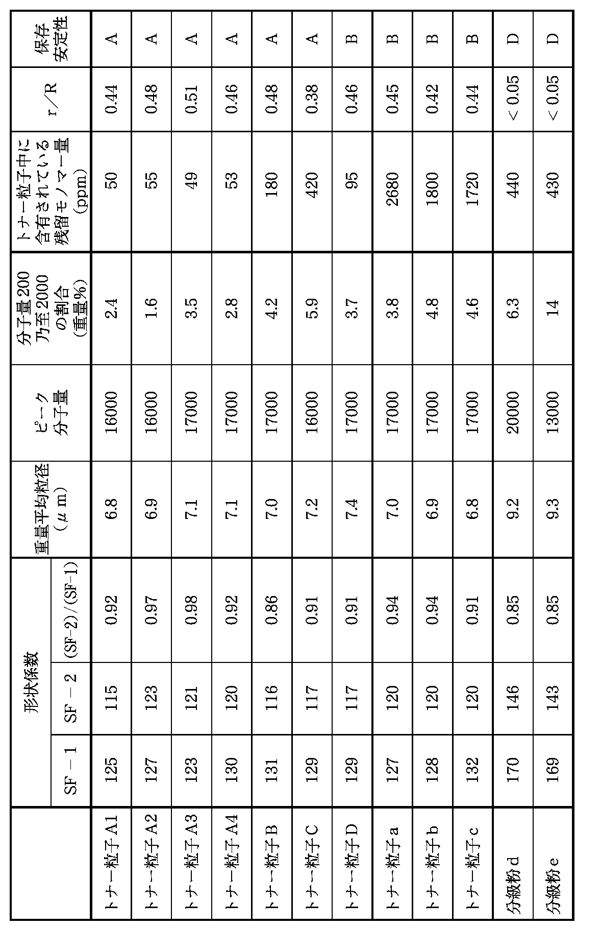
黒トナー粒子(A1)は、重量平均粒径が6.4μm、個数分布による変動係数が25%であり、形状係数SF−1が127、SF−2が115、(SF−2)/(SF−1)が0.91であった。また、トナー粒子中の結着樹脂のピーク分子量が1.9万で、GPC分子量200乃至2000の割合が2.4重量%であった。
【0189】
該黒トナー粒子(A1)中のワックス成分及び着色剤の分散状態を透過型電子顕微鏡(TEM)で4万倍、又は、10万倍に拡大し観察したところ、図7(a)の模式図のように結着樹脂の内部にワックス成分が粒状に内包化されており、該ワックス成分中に樹脂成分及びカーボンブラックが分散した海−島−海構造を有していた。またトナー粒子の断層面の長径Rと、長径Rであるトナー粒子の断層面中に存在しているワックスに起因する相分離構造の中で最も大きなものの長径rとの比r/Rの平均値は、0.44であった。さらにワックスに起因する相分離構造の長径rと、長径rであるワックス成分中の樹脂成分に起因する相分離構造の中で最も大きなものの長径aとの比a/rの平均値は、0.31であった。また、結着樹脂中とワックス成分中のカーボンブラックの投影面積比率は20:80であり、トナーに含有される残留モノマーの含有量は50ppmであった。
【0190】
着色剤をカーボンブラックから、マゼンタ着色剤としてC.I.Pigment Red 202、シアン着色剤としてC.I.Pigment Blue 15:3、イエロー着色剤としてC.I.Pigment Yellow 17にかえる以外は、同様にして、マゼンタトナー粒子(A2)、シアントナー粒子(A3)、イエロートナー粒子(A4)を製造した。それぞの物性は表1に示す。
【0191】
各トナー粒子(A2)〜(A4)中のワックス成分及び着色剤の分散状態を透過型電子顕微鏡(TEM)で観察したところ、図7(a)の模式図のように結着樹脂の内部にワックス成分が粒状に内包化されており、該ワックス成分中に樹脂成分及び着色剤が分散した海−島−海構造を有していた。
【0192】
上記のトナー粒子(A1)〜(A4)について以下の様にして保存安定性の評価を行なったところ、粒子の流動性が損なわれることなく、良好な結果となった。
【0193】
<保存安定性の評価方法>
粒子5.0gを50mlのプラスチック製カップに入れ、50.0℃に設定した熱風乾燥器中に静置する。3日後に取り出して室温まで放冷し、目視により次の基準で保存安定性を評価した。
A:流動性が損なわれない。
B:流動性が落ちているが、カップを回転させると流動性が回復する。
C:トナー粒子の凝集や粗粒化が見られる。
D:ケーキングが発生している。
【0194】
上記トナー粒子(A1)〜(A4)100重量部と疎水性シリカ微粉体(BET比表面積:200m2/g)2重量部をヘンシェルミキサーで乾式混合して、本発明のトナー(A1)〜(A4)とした後、各トナー(A1)〜(A4)6重量部と樹脂コート磁性フェライトキャリア(重量平均粒径=50μm)94重量部とを混合して磁気ブラシ現像用の二成分現像剤(A1)〜(A4)を調製した。
【0195】
トナーの製造例2
水系媒体から取り出された重合体粒子を、常圧,40℃の環境下で40時間熱風乾燥することにより乾燥させること以外は、トナーの製造例1における黒トナー粒子(A1)の製造と同様にして、トナー粒子(B)を製造した。
【0196】
得られたトナー粒子(B)の物性を表1に示す。
【0197】
該トナー粒子(B)中のワックス成分及び着色剤の分散状態を透過型電子顕微鏡(TEM)で観察したところ、図7(a)の模式図のように結着樹脂の内部にワックス成分が粒状に内包化されており、該ワックス成分中に樹脂成分及びカーボンブラックが分散した海−島−海構造を有していた。また、結着樹脂中とワックス成分中のカーボンブラックの投影面積比率は30:70であった。
【0198】
該トナー粒子(B)を用いて、トナーの製造例1と同様にして、トナー(B)及び二成分現像剤(B)を作製した。
【0199】
トナーの製造例3
水系媒体から取り出された重合体粒子を、常圧,35℃の環境下で20時間熱風乾燥することにより乾燥させること以外は、トナーの製造例1における黒トナー粒子(A1)の製造と同様にして、トナー粒子(C)を製造した。
【0200】
得られたトナー粒子(C)の物性を表1に示す。
【0201】
該トナー粒子(C)中のワックス成分及び着色剤の分散状態を透過型電子顕微鏡(TEM)で観察したところ、図7(a)の模式図のように結着樹脂の内部にワックス成分が粒状に内包化されており、該ワックス成分中に樹脂成分及びカーボンブラックが分散した海−島−海構造を有していた。また、結着樹脂中とワックス成分中のカーボンブラックの投影面積比率は41:59であった。
【0202】
該トナー粒子(C)を用いて、トナーの製造例1と同様にして、トナー(C)及び二成分現像剤(C)を作製した。
【0203】
トナーの製造例4
トナーの製造例1の黒トナー粒子(A1)の製造において、飽和ポリエステル及び不飽和ポリエステルを用いなかったこと以外は、同様にして、トナー粒子(D)を製造した。
【0204】
得られたトナー粒子(D)の物性を表1に示す。
【0205】
該トナー粒子(D)中のワックス成分及び着色剤の分散状態を透過型電子顕微鏡(TEM)で観察したところ、図7(a)の模式図のように結着樹脂の内部にワックス成分が粒状に内包化されており、該ワックス成分中に樹脂成分及びカーボンブラックが分散した海−島−海構造を有していた。また、結着樹脂中とワックス成分中のカーボンブラックの投影面積比率は21:79であった。
【0206】
該トナー粒子(D)を用いて、トナーの製造例1と同様にして、トナー(D)及び二成分現像剤(D)を作製した。
【0207】
トナーの比較製造例1
高速撹拌装置TK式ホモミキサー(特殊機化工業製)を備えた2リットル用4つ口セパラブルフラスコ中にイオン交換水650重量部と0.1mol/リットル−Na3PO4水溶液500重量部を投入し、回転数を12000rpmに調整し、70℃に加温した。ここに1.0mol/リットル−CaCl2水溶液70重量部を徐々に添加し、微小な難水溶性分散安定剤Ca3(PO4)を含む水系連続相を調製した。
【0208】
一方、分散質として
・スチレン 39重量部
・n−ブチルアクリレート 11重量部
・カーボンブラック 10重量部
(BET比表面積=80m2/g、吸油量=120ml/100g)
・負電荷性制御剤(アゾ系鉄錯体) 2重量部
上記混合物をアトライター(三井三池化工製)を用い3時間分散したものに、
・トナーの製造例1で使用した長鎖分岐を有する 50重量部
ポリアルキレンワックス(最大吸熱ピーク温度=70℃)
・2,2’−アゾビス(2,4−ジメチルバレロニトリル) 10重量部
を添加して70℃に加熱し、重合性単量体組成物を調製した。
【0209】
次に前記水系媒体中に該重合性単量体組成物を投入し、窒素雰囲気下液温70℃で高速撹拌機の回転数を12000rpmに維持しつつ15分間撹拌し、造粒した。その後、撹拌機をプロペラ型撹拌翼にかえて50rpmで撹拌しながら70℃で10時間保持して懸濁液を得た。
【0210】
さらに、上記懸濁液を放冷し下記の混合物を滴下した後、再び70℃に昇温して10時間保持した。
【0211】
・スチレン 88重量部
・n−ブチルアクリレート 12重量部
・2,2’−アゾビス(2,4−ジメチルバレロニトリル) 5重量部
【0212】
その後、懸濁液を冷却し、次いで希塩酸を添加して分散安定剤を除去した。さらに水洗浄を数回繰り返した後、常圧,35℃の環境下で10時間熱風乾燥し、比較用トナー粒子(a)を得た。
【0213】
得られた比較用トナー粒子(a)の物性を表1に示す。
【0214】
該トナー粒子(a)中のワックス成分及び着色剤の分散状態を透過型電子顕微鏡(TEM)で観察したところ、図7(a)の模式図のように結着樹脂の内部にワックス成分が粒状に内包化されており、該ワックス成分中に樹脂成分及びカーボンブラックが分散した海−島−海構造を有していた。また、結着樹脂中とワックス成分中のカーボンブラックの投影面積比率は72:28であった。
【0215】
該比較用トナー粒子(a)を用いて、トナーの製造例1と同様にして、比較用トナー(a)及び比較用二成分現像剤(a)を作製した。
【0216】
トナーの比較製造例2
高速撹拌装置TK式ホモミキサー(特殊機化工業製)を備えた2リットル用4つ口セパラブルフラスコ中にイオン交換水650重量部と0.1mol/リットル−Na3PO4水溶液500重量部を投入し、回転数を12000rpmに調整し、70℃に加温した。ここに1.0mol/リットル−CaCl2水溶液70重量部を徐々に添加し、微小な難水溶性分散安定剤Ca3(PO4)を含む水系連続相を調製した。
【0217】
一方、分散質として
・スチレン 127重量部
・n−ブチルアクリレート 24重量部
・カーボンブラック 10重量部
(BET比表面積=80m2/g、吸油量=120ml/100g)
・負電荷性制御剤(アゾ系鉄錯体) 2重量部
上記混合物をアトライター(三井三池化工製)を用い3時間分散したものに、
・パラフィンワックス(最大吸熱ピーク温度=70℃) 50重量部
・2,2’−アゾビス(2,4−ジメチルバレロニトリル) 10重量部
を添加して70℃に加熱し、重合性単量体組成物を調製した。
【0218】
次に前記水系媒体中に該重合性単量体組成物を投入し、窒素雰囲気下液温70℃で高速撹拌機の回転数を12000rpmに維持しつつ15分間撹拌し、造粒した。その後、撹拌機をプロペラ型撹拌翼にかえて50rpmで撹拌しながら70℃で10時間保持して懸濁液を得た。その後、懸濁液を冷却し、次いで希塩酸を添加して分散安定剤を除去した。さらに水洗浄を数回繰り返した後、常圧,35℃の環境下において20時間熱風乾燥し、比較用トナー粒子(b)を得た。
【0219】
得られた比較用トナー粒子(b)の物性を表1に示す。
【0220】
該トナー粒子(b)中のワックス成分及び着色剤の分散状態を透過型電子顕微鏡(TEM)で観察したところ、図7(b)の模式図のように結着樹脂の内部にワックス成分が粒状に内包化されていた。またワックス成分中におけるカーボンブラックの分散は観察されなかった。
【0221】
該比較用トナー粒子(b)を用いて、トナーの製造例1と同様にして、比較用トナー(b)及び比較用二成分現像剤(b)を作製した。
【0222】
トナーの比較製造例3
用いるワックス成分を最大吸熱ピーク温度57℃のパラフィンワックスにかえる以外は、トナーの比較製造例2と同様にして、比較用トナー粒子(c)を得た。
【0223】
得られた比較用トナー粒子(c)の物性を表1に示す。
【0224】
該トナー粒子(c)中のワックス成分及び着色剤の分散状態を透過型電子顕微鏡(TEM)で観察したところ、図7(b)の模式図のように結着樹脂の内部にワックス成分が粒状に内包化されていた。またワックス成分中におけるカーボンブラックの分散は観察されなかった。
【0225】
該比較用トナー粒子(c)を用いて、トナーの製造例1と同様にして、比較用トナー(c)及び比較用二成分現像剤(c)を作製した。
【0226】
トナーの比較製造例4
・スチレン/n−ブチルアクリレート樹脂 150重量部
(ピーク分子量20000、重量平均分子量/数平均分子量=1.8、ガラス転移温度=60℃)
・トナーの製造例1で用いた飽和ポリエステル樹脂 4重量部
・トナーの製造例1で用いた不飽和ポリエステル樹脂 1重量部
・トナーの製造例1で用いたカーボンブラック 10重量部
・トナーの製造例1で用いた負電荷性制御剤 2重量部
・最大吸熱ピーク60℃のパラフィンワックス 6重量部
【0227】
上記成分を二軸エクストルーダーで溶融混練し、冷却した混練物をハンマーミルで粗粉砕した後、粗粉砕物をジェットミルで微粉砕し、分級して分級粉(d)とした。
【0228】
得られた分級粉(d)の物性を表1に示す。
【0229】
該分級粉(d)中のワックス成分及び着色剤の分散状態を透過型電子顕微鏡(TEM)で観察したところ、図7(c)の模式図のように結着樹脂の内部にワックス成分が微分散していた。またワックス成分中におけるカーボンブラックの分散は観察されなかった。
【0230】
該分級粉(d)を用いて、トナーの製造例1と同様にして、比較用トナー(d)及び比較用二成分現像剤(d)を作製した。
【0231】
トナーの比較製造例5
・スチレン/n−ブチルアクリレート樹脂 150重量部
(ピーク分子量13000、重量平均分子量/数平均分子量=1.6、
ガラス転移温度=60℃)
・トナーの製造例1で用いた飽和ポリエステル樹脂 4重量部
・トナーの製造例1で用いた不飽和ポリエステル樹脂 1重量部
・トナーの製造例1で用いたカーボンブラック 10重量部
・トナーの製造例1で用いた負電荷性制御剤 2重量部
・最大吸熱ピーク60℃のパラフィンワックス 6重量部
【0232】
上記成分を二軸エクストルーダーで溶融混練し、冷却した混練物をハンマーミルで粗粉砕した後、粗粉砕物をジェットミルで微粉砕し、分級して分級粉(e)とした。
【0233】
得られた分級粉(e)の物性を表1に示す。
【0234】
該分級粉(e)中のワックス成分及び着色剤の分散状態を透過型電子顕微鏡(TEM)で観察したところ、図7(c)の模式図のように結着樹脂の内部にワックス成分が微分散していた。またワックス成分中におけるカーボンブラックの分散は観察されなかった。
【0235】
該分級粉(e)を用いて、トナーの製造例1と同様にして、比較用トナー(e)及び比較用二成分現像剤(e)を作製した。
【0236】
【表1】
〔実施例並びに比較例〕
実施例1
本実施例に用いた画像形成装置について説明する。図1は本実施例に適用される画像形成装置の断面の概略図であり、図2は画像形成装置の現像装置図である。
【0238】
感光体ドラム1は、基材1a上に有機光半導体を有する感光層1bを有し、矢印方向に回転し、対向し接触回転する帯電ローラー2(導電性弾性層2a、芯金2b)により感光体ドラム1上に約−600Vの表面電位に帯電させる。露光3は、ポリゴンミラーにより感光体上にデジタル画像情報に応じてオン−オフさせることで露光部電位が−100V、暗部電位が−600Vの静電荷像が形成される。二成分現像剤(A1)を有している現像器4−1を用い黒トナー(A1)を感光体1上に反転現像法を用いトナー像を得た。該トナー像は中間転写体5上に転写され、感光体1上の転写残トナーはクリーニング部材8により、残トナー容器9の中に回収される。
【0239】
中間転写体5は、パイプ上の芯金5b上にカーボンブラックをニトリル−ブタジエンラバー(NBR)中に充分分散させた弾性層5aをコーティングしたものであり、該コート層5aの硬度は「JIS K−6301」に準拠し30度で、かつ体積固有抵抗値は109Ω・cmであった。感光体1から中間転写体5への転写に必要な転写電流は約5μAであり、これは電源より+500Vを芯金5b上に付与することで得られた。
【0240】
転写ローラ7の外径は20mmであり、該転写ローラ7は直径10mmの芯金7b上にカーボンの導電性付与部材をエチレン−プロピレン−ジエン系三元共重合体(EPDM)の発泡体中に充分分散させたものをコーティングすることにより生成した弾性層7aを有し、弾性層7aの体積固有抵抗値は106Ω・cmで、「JIS K−6301」の基準の硬度は35度の値を示すものを用いた。転写ローラには電圧を印加して15μAの転写電流を流した。
【0241】
加熱定着装置Hにはオイル塗布機能のない熱ロール方式の定着装置を用いた。この時上部ローラー、下部ローラー共にフッ素系樹脂の表面層を有するものを使用し、ローラーの直径は60mmであった。また、定着温度は130℃、ニップ幅を7mmに設定した。
【0242】
以上の設定条件で、常温常湿(25℃,60%RH)、高温高湿(35℃,85%RH)環境下で一週間放置した。その後12枚/分(A4サイズ)のプリントアウト速度で現像剤(A1)を逐次補給しながら単色での連続モード(すなわち、現像器を休止させることなくトナーの消費を促進させるモード)でプリントアウト試験を行い、得られた5000枚のプリントアウト画像を後述の項目について評価した。
【0243】
更に、常温常湿下において100枚のベタ白画像をプリントアウトし、トナー層厚規制部材に対するトナーの融着を観察した。
【0244】
以上の評価結果を表2及び3に示す。
【0245】
更に、上記の画像形成装置の現像器4−2〜4−4に二成分現像剤(A2)〜(A4)を導入して、フルカラーの画像形成を行なった。得られた画像は透明性と彩度に優れており、色ムラ等の画像不良の発生の生じていない高品位な画像が得られた。また、画像形成装置とのマッチングに関しても問題の無いものであった。
【0246】
実施例2乃至4
実施例1において、用いる現像剤を二成分現像剤(B)〜(D)にかえる以外は、同様にしてプリントアウト試験を行ない、評価を行なった。評価結果を表2及び3に示す。
【0247】
比較例1乃至5
実施例1において、用いる現像剤を二成分現像剤(a)〜(e)にかえる以外は、同様にしてプリントアウト試験を行ない、評価を行なった。評価結果を表2及び3に示す。
【0248】
【表2】
【表3】
実施例5及び比較例6
図2に示す画像形成装置の現像装置を図3に示すものに交換し、トナー担持体の移動速度が静電潜像担持体面の移動速度に対し、3.0倍となるように設定し、トナー(A1)と比較トナー(a)の各々を逐次補給しながら単色での間歇モード(すなわち、1枚プリントアウトする毎に10秒間現像器を休止させ、再起動時の現像装置の予備動作でトナーの劣化を促進させるモード)により前記実施例と同様に評価を行った。尚、現像装置には常温常湿および高温高湿環境下で一週間放置したトナーを充填した。
【0251】
また、同時に用いた画像形成装置と上記現像剤のマッチングについても評価した。
【0252】
ここで用いたトナー担持体の表面粗度Raは1.5であり、トナー規制ブレードはリン青銅ベース板にウレタンゴムを接着し、トナー担持体との当接面をナイロンによりコートしたものを用いた。評価結果を表4及び5に示す。
【0253】
【表4】
【表5】
実施例6及び比較例7
本実施例では市販のレーザービームプリンターLBP−EX(キヤノン社製)にリユース機構を取り付け改造し、再設定して用いた。即ち、図4において、感光体ドラム上の未転写トナーを該感光体ドラムに当接しているクリーナーの弾性ブレードによりかき落とした後、クリーナーローラーによってクリーナー内部へ送り、更にクリーナースクリューを経て、搬送スクリューを設けた供給用パイプによってホッパーを介して現像器に戻し、再度、回収トナーを利用するシステムを取り付け、一次帯電ローラーとしてナイロン樹脂で被覆された導電性カーボンを分散したゴムローラー(直径12mm,当接圧50g/cm)を使用し、静電潜像担持体にレーザー露光(600dpi)により暗部電位VD=−700V、明部電位VL=−200Vを形成した。トナー担持体として表面にカーボンブラックを分散した樹脂をコートした表面粗度Raが1.1を呈する現像スリーブを感光ドラム面の移動速度に対して1.1倍となる様に設定し、次いで、感光体ドラムと該現像スリーブとの間隙(S−D間)を270μmとし、トナー規制部材としてウレタンゴム製ブレードを当接させて用いた。現像バイアスとして直流バイアス成分に交流バイアス成分を重畳して用いた。
【0256】
また、加熱定着装置Hには図5及び6に示した定着装置を用い、加熱体31の検温素子31dの表面温度は130℃、加熱体21−シリコーンゴムの発泡体を下層に有するスポンジ加圧ローラー33間の層圧は8kg、加圧ローラーとフィルムのニップは6mmとし、定着フィルム32には、転写材との接触面にPTEF(高分子量タイプ)に導電性物質を分散させた低抵抗の離型層を有する厚さ60μmの耐熱性ポリイミドフィルムを使用した。
【0257】
以上の設定条件で、常温常湿(25℃,60%RH)、高温高湿(35℃,85%RH)環境下、一週間放置した。その後12枚/分(A4サイズ)のプリントアウト速度でトナー(A1)および比較トナー(a)の各々を逐次補給しながら間歇モード(すなわち、1枚プリントアウトする毎に10秒間現像器を休止させ、再起動時の現像装置の予備動作でトナーの劣化を促進させるモード)でプリントアウト試験を行い、得られたプリントアウト画像を後述の項目について評価した。
【0258】
また、同時に用いた画像形成装置と上記トナーのマッチングについても評価した。
【0259】
評価結果を表6及び7に示す。
【0260】
【表6】
【表7】
本発明の実施例及び比較例中に記載の評価項目の説明とその評価基準について述べる。
【0263】
[アウトプット画像評価]
<1>画像濃度
常温常湿環境下における100枚目、高温高湿環境下における300枚目のプリントアウト画像について画像濃度を評価した。尚、画像濃度は「マクベス反射濃度計」(マクベス社製)を用いて、原稿濃度が0.00の白地部分のプリントアウト画像に対する相対濃度を測定した。
A:1.40以上
B:1.35以上、1.40未満
C:1.00以上、1.35未満
D:1.00未満
【0264】
<2>カブリ
常温常湿環境下における100枚目、および高温高湿環境下における300枚目のプリントアウト画像の白地部分の白色度と転写紙の白色度の差から、カブリ濃度(%)を算出し、画像カブリを評価した。尚、カブリ濃度は「リフレクトメーター」(東京電色社製)により測定した。
A:1.5%未満
B:1.5%以上、2.5%未満
C:2.5%以上、4.0%未満
D:4.0%以上
【0265】
<3>定着性
定着性は、常温常湿環境下における100枚目のプリントアウト画像に対して、50g/cm2の荷重をかけ、柔和な薄紙により摺擦し、摺擦前後での画像濃度の低下率(%)で評価した。なお、転写紙としては128g/m2の紙を用いた。
A:5%未満
B:5%以上、10%未満
C:10%以上、20%未満
D:20%以上
【0266】
[画像形成装置マッチング評価]
<1>現像スリーブとのマッチング
プリントアウト試験終了後、現像スリーブ表面への残留トナーの固着の様子を目視で評価した。
A:固着は未発生。
B:固着はほとんど発生せず。
C:多少固着がある。
D:固着が多い。
【0267】
<2>感光ドラムとのマッチング
プリントアウト試験終了後、感光体ドラム表面の傷や残留トナーの固着の発生状況を目視で評価した。
A:傷及び固着は未発生。
B:わずかに傷の発生が見られる。
C:固着や傷がある。
D:固着が多い。
【0268】
<3>中間転写体とのマッチング
プリントアウト試験終了後、中間転写体表面の傷や残留トナーの固着状況を目視で評価した。
A:傷及び固着は未発生。
B:表面に残留トナーの存在が認められる。
C:固着や傷がある。
D:固着が多い。
【0269】
<4>定着装置とのマッチング
プリントアウト試験終了後、定着フィルム表面の傷や残留トナーの固着状況を目視で評価した。
A:未発生。
B:わずかに固着が見られる。
C:固着や傷がある。
D:固着が多い。
【0270】
[トナー層厚規制部材に対する融着]
A:融着は未発生。
B:融着はほどんど発生せず。
C:多少融着がある。
D:融着が多い。
【0271】
【発明の効果】
以上説明した様に、本発明によれば、ワックス成分を結着樹脂中に特定の状態で存在させることにより、極めて画像の色味が良好で、かつ、グロスの適正な高品位の画像を長期にわたって形成することができる。また、感光体等にトナー粒子を融着させることなく高効率で転写することが可能となり、画像形成装置とのマッチングも好適なものとなる。
【図面の簡単な説明】
【図1】本発明に好適な画像形成装置の概略的説明図である。
【図2】本発明の実施例に用いた二成分現像剤用の現像装置の要部の拡大横断面図である。
【図3】本発明の実施例に用いた一成分現像剤用の現像装置の要部の拡大横断面図である。
【図4】未転写トナーをリユースする画像形成装置の概略的説明図である。
【図5】本発明の実施例に用いた定着装置の要部の分解斜視図である。
【図6】本発明の実施例に用いた定着装置の非駆動時のフィルム状態を示した要部の拡大横断面図である。
【図7】トナーの断面の特徴を表す模式図である。
【符号の説明】
1 感光体(静電潜像担持体)
2 帯電ローラー
3 露光
4 4色現像器(4−1、4−2、4−3、4−4)
5 中間転写体
6 転写材
7 転写ローラ
11 現像剤担持体
13 感光体ドラム
30 ステー
31 加熱体
31a ヒーター基板
31b 発熱体
31c 表面保護層
31d 検温素子
32 定着フィルム
33 加圧ローラー
34 コイルばね
35 フィルム端部規制フランジ
36 給電コネクター
37 断電部材
38 入口ガイド
39 出口ガイド(分離ガイド)[0001]
BACKGROUND OF THE INVENTION
The present invention relates to a toner used in a recording method using an electrophotographic method, an electrostatic recording method, a magnetic recording method, a toner jet method, and the like, and an image forming method using the toner. More specifically, the present invention relates to a toner used in an image recording apparatus that can be used in a copying machine, a printer, a facsimile, a plotter, and the like, and an image forming method using the toner.
[0002]
[Prior art]
Conventionally, as an electrophotographic method, many methods are known as described in US Pat. No. 2,297,691, Japanese Patent Publication No. 42-23910, Japanese Patent Publication No. 43-24748, and the like. In general, a photoconductive substance is used, and an electric latent image is formed on the photoreceptor by various means, and then the latent image is developed with toner, and a direct or indirect means is used as necessary. Used to transfer a toner image onto a transfer material such as paper, and then fix it by heating, pressing, or solvent vapor to obtain a copy, etc., and untransferred toner that remains without being transferred onto the photoreceptor Is cleaned in various ways and the above steps are repeated.
[0003]
An example of a general method for forming a full-color image will be described. A photoreceptor (electrostatic latent image carrier) of a photoreceptor drum is uniformly charged by a primary charger, and is modulated by a magenta image signal of an original. Image exposure is performed with the laser beam, an electrostatic latent image is formed on the photosensitive drum, and the electrostatic latent image is developed by a magenta developing device having magenta toner, thereby forming a magenta toner image. Subsequently, the magenta toner image developed on the photosensitive drum by the transfer charger is transferred to the transferred transfer material directly or indirectly using a transfer charger.
[0004]
On the other hand, the photosensitive drum after the development of the electrostatic latent image is neutralized by a neutralizing charger, cleaned by a cleaning unit, and then charged by a primary charger again. The cyan toner image is formed on the transfer material onto which the magenta toner image has been transferred, and the toner images of four colors are transferred to the transfer material in the same manner as yellow and black. The transfer material having the four color toner images is fixed by the action of heat and pressure by a fixing roller, thereby forming a full color image.
[0005]
In recent years, such devices have been used not only in office copy machines for copying original documents, but also in the fields of laser beam printers (LBP) as computer output or personal copy (PC) for individuals. I started.
[0006]
In addition to the fields represented by LBP and PC, the development of plain paper fax machines using basic engines is also rapidly developing.
[0007]
As a result, smaller, lighter and faster speeds, higher image quality, and higher reliability are being sought after, and machines are becoming simpler in various ways. As a result, the performance required for the toner becomes higher, and if the improvement in the performance of the toner cannot be achieved, a better machine cannot be realized. In recent years, the demand for color copying has been increasing rapidly due to various copying needs, and further higher image quality and higher resolution are desired in order to copy original color images more faithfully. Furthermore, there is an increasing demand for copying original color originals on both sides.
[0008]
From these viewpoints, the toner used in the color image forming method must have good meltability and color mixing when heated, and has a low softening point and a low melt viscosity. It is preferable to use a high toner.
[0009]
That is, by using such sharp melt toner, it is possible to widen the color reproduction range of the copy and obtain a color copy faithful to the original image.
[0010]
However, such a color toner having a high sharp melt property generally has a high affinity with the fixing roller, and tends to be offset to the fixing roller during fixing.
[0011]
In particular, in the case of a fixing device in a color image forming apparatus, since a plurality of toner layers of magenta, cyan, yellow, and black are formed on a transfer material, an offset tends to easily occur due to an increase in toner layer thickness.
[0012]
Conventionally, for the purpose of preventing toner from adhering to the surface of the fixing roller, for example, the roller surface is coated with a material excellent in releasability with respect to the toner, such as silicone rubber or fluorine resin, and further, the surface is prevented from being offset, and In order to prevent the roller surface from being fatigued, the roller surface is coated with a thin film of a liquid having high releasability such as silicone oil or fluorine oil. However, this method is extremely effective in preventing toner offset, but has a problem that the fixing device is complicated because an apparatus is required to supply the liquid for preventing offset. Needless to say, this application of oil causes a delamination between the layers constituting the fixing roller, resulting in an adverse effect of promoting the shortening of the life of the fixing roller.
[0013]
Therefore, instead of using a silicone oil supply device, instead of supplying an offset prevention liquid from the toner during heating, there is a method of adding a release agent such as low molecular weight polyethylene or low molecular weight polypropylene to the toner. Proposed.
[0014]
For example, Japanese Patent Publication No. 52-3304, Japanese Patent Publication No. 52-3305, Japanese Patent Laid-Open No. 57-52574, and the like have disclosed a technique for incorporating a wax as a releasing agent in the toner.
[0015]
JP-A-3-50559, JP-A-2-79860, JP-A-1-109359, JP-A-62-1166, JP-A-61-273554, JP-A-61-94062. JP-A-61-138259, JP-A-60-252361, JP-A-60-252360, JP-A-60-217366, etc. disclose techniques for containing waxes. Yes.
[0016]
Waxes are used to improve the offset resistance of toner at low and high temperatures, and to improve fixability at low temperatures. When exposed to heat due to temperature rise or the like, or when the toner is left for a long time, the wax migrates to the toner surface and developability deteriorates.
[0017]
In view of these problems, the expectation for development of a new toner has been great.
[0018]
A suspension polymerization toner has been proposed for the above problem (Japanese Patent Publication No. 36-10231). In this suspension polymerization method, a monomer composition is prepared by uniformly dissolving or dispersing a polymerizable monomer and a colorant (and, if necessary, a polymerization initiator, a crosslinking agent, a charge control agent, and other additives). Then, the monomer composition is dispersed in a continuous phase (for example, an aqueous phase) containing a dispersion stabilizer by using a suitable stirrer, and simultaneously subjected to a polymerization reaction, whereby toner particles having a desired particle size are obtained. Is what you get.
[0019]
In this suspension polymerization method, droplets of the monomer composition are generated in a dispersion medium having a large polarity such as water. Therefore, the component having a polar group contained in the monomer composition is an interface with the aqueous phase. Therefore, it is possible to form a so-called core / shell structure in which a nonpolar component is not easily present in the surface layer portion. That is, the toner produced by the polymerization method can achieve the conflicting performances of low temperature fixing property, blocking resistance and durability, and high temperature offset resistance by encapsulating the wax component as a release agent, and a fixing roller. It is possible to prevent high temperature offset without applying a release agent such as oil.
[0020]
In JP-A-6-194877, a crystalline (meth) acrylate polymer is formed as a plurality of domains in a binder resin matrix, and the binder resin contains a plurality of domains in the domain. And a toner having a sea-island-sea structure is disclosed. According to this publication, a toner having excellent high-temperature offset resistance can be obtained by using crystalline poly (meth) acrylate behenyl having a relatively high melt viscosity having a weight average molecular weight of 35,000 to 500,000 as a high-temperature offset preventive agent. However, since the melt viscosity of the crystalline poly (meth) acrylate behenyl used is too high, the low-temperature fixability is poor and further improvement is required. In addition, since the high temperature offset preventive agent is crystalline, for example, it has poor light transmittance when printed out to OHP and is difficult to apply to a full color toner.
[0021]
Further, even if the toner has a sea-island-sea structure, if the amount of residual monomer in the toner is large, the resin in the wax component becomes compatible with the wax when the toner is left for a long time. Since the sea-island-sea structure is broken, the effect of having the sea-island-sea structure cannot be obtained sufficiently, and the mechanical strength of the toner particles is likely to be lowered.
[0022]
By the way, various pigments and dyes which are colorants are contained as essential components in the toner particles, but these colorants are often hygroscopic, resulting in problems in environmental stability. May occur. As a method for solving this problem, Japanese Patent Application Laid-Open No. 63-19663 discloses a spherical toner in which the amount of carbon black exposed on the surface is suppressed, and Japanese Patent Application Laid-Open No. 5-289396 discloses the presence of a dispersion aid. A full-color toner containing yellow, magenta, and cyan colorants that prevents the colorant from being exposed to the toner surface by finely dispersing the domain resin in which the colorant is dispersed in the lower thermoplastic matrix resin. It is disclosed. According to these publications, it is possible to obtain a toner having stable charging characteristics regardless of environmental humidity by suppressing exposure of the colorant having hygroscopicity to the toner surface. However, in the case of the toner described in JP-A-63-19663, the blackness of the image is insufficient, and in the case of the toner described in JP-A-5-289396, It is difficult to say that it has sufficient low-temperature fixability.
[0023]
Conventionally, in a full-color copying machine, four photoreceptors and a belt-like transfer belt are used, and an electrostatic latent image formed on each photoreceptor is developed with cyan, magenta, yellow, and black toners, and then the photoreceptor and After transferring the transfer material between the belt transfer bodies and transferring between straight paths, a full color image is formed, or the transfer material is wound around the surface of the transfer body facing the photosensitive member by mechanical action such as electrostatic force or gripper, A method of obtaining a full-color image as a result of performing the development-transfer process four times is generally used.
[0024]
In recent years, there has been an increasing need for various materials to be applied to small-size paper such as cardboard, cards, and postcards in addition to normal paper and overhead projector film (OHP) as full-color copying materials. In the method using the four photoconductors described above, since the transfer material is conveyed straight, the application range to various transfer materials is wide. However, it is necessary to accurately superimpose a plurality of toner images on the position of a predetermined transfer material. However, there is a problem that it is difficult to obtain a high-quality image with high reproducibility even with a slight difference in registration, and the transfer material conveyance mechanism becomes complicated, leading to a decrease in reliability and an increase in the number of parts. In addition, when using thick paper with a large amount of weight by adsorbing and winding the transfer material on the surface of the transfer body, the trailing edge of the transfer material causes poor adhesion due to the stiffness of the transfer material, resulting in an image based on transfer. It causes defects and is not preferable. Similarly, image defects may occur on small-size paper.
[0025]
A full-color image device using a drum-shaped intermediate transfer member is already known from US Pat. No. 5,187,526 and Japanese Patent Laid-Open No. 4-16426. In U.S. Pat. No. 5,187,526, the volume specific resistance value of an intermediate transfer roller having a polyurethane-based surface layer is 10.9The volume specific resistance value of a transfer roller that is less than Ω · cm and is composed of a similar surface layer is 10TenIt is described that high image quality can be obtained by setting the resistance to Ω · cm or more. However, in such a system, a high output electric field is required in order to give a sufficient amount of transfer charge to the toner when transferring the toner to the transfer material. Therefore, the system is made of polyurethane in which a conductivity imparting material is dispersed. The surface layer is locally broken down, which causes undesirable image distortion in a halftone image with a small amount of toner. Furthermore, the application of such a high voltage tends to cause a transfer failure due to a transfer current leaking with a decrease in resistance of the transfer material in an environment under a high humidity where the relative humidity exceeds 60% RH. However, even in a low humidity environment of 40% RH or less, it may cause a transfer failure due to uneven resistance unevenness of the transfer material.
[0026]
JP-A-59-15739 and JP-A-59-5046 disclose the relationship between the configuration using an intermediate transfer member and toner. However, this publication only describes that a toner having a thickness of 10 μm or less is efficiently transferred using an adhesive intermediate transfer member. In a system that normally uses an intermediate transfer member, it is necessary to transfer the developed color image of the toner from the photosensitive member to the intermediate transfer member, and then transfer it again from the intermediate transfer member onto the transfer material. It is necessary to increase the transfer efficiency of the specific toner more than before. In particular, in the case of using a full-color copying machine that transfers a plurality of toner images after development, the amount of toner on the photoconductor increases as compared with the case of one-color black toner used in a black-and-white copying machine. It is difficult to improve the transfer efficiency only with use. Further, when a normal toner is used, the surface of the photoconductor or the surface of the photoconductor due to the displacement or rubbing force between the photoconductor or the intermediate transfer body and the cleaning member and / or between the photoconductor and the intermediate transfer body Due to toner fusing or filming on the surface of the intermediate transfer member, transfer efficiency is deteriorated, and in full color, the four color toner images are not transferred uniformly, so problems are likely to occur in terms of color unevenness and color balance. Therefore, it has been difficult to stably output a high-quality full-color image.
[0027]
In addition, as a toner mounted on a normal full-color copying machine, it is necessary that the color toners are sufficiently mixed in the fixing process. This makes it important to improve color reproducibility and transparency of the OHP image. In general, it is preferable to use a sharp melt and low molecular weight resin for the toner and the specific color toner. For normal black toner, a release agent having relatively high crystallinity represented by polyethylene wax or polypropylene wax is used in order to improve high temperature offset resistance during fixing. However, in the full-color toner, the transparency of the OHP toner image is remarkably hindered due to the crystallinity of the release agent. For this reason, normally, silicone oil or the like is uniformly applied to the heat-fixing roller without adding a release agent as a color toner component, and as a result, high temperature offset resistance is improved. However, the transfer material having the toner-fixed image obtained in this way is not preferable because it causes an uncomfortable feeling when used by the user because extra silicone oil or the like adheres to the surface. As described above, full-color image formation using an intermediate transfer member having many contact portions has many problems that are difficult at present. Japanese Patent Application Laid-Open Nos. 59-15739 and 59-5046 do not propose any device for the toner or the intermediate transfer member in this regard.
[0028]
[Problems to be solved by the invention]
An object of the present invention is to provide a toner having good low-temperature fixability and storage stability and excellent durability, and an image forming method using the toner.
[0029]
An object of the present invention is to provide a toner having good image color and suitable gloss, and an image forming method using the toner.
[0030]
[Means and Actions for Solving the Problems]
Main departureIn a toner having toner particles containing at least a binder resin, a colorant and a wax component,
When the tomographic plane of the toner particles is observed using a transmission electron microscope (TEM), the wax component is dispersed in a granular form in the binder resin, and a part of the binder resin in the wax component. Are dispersed in granular form,
The present invention relates to a toner, wherein the content of residual monomer contained in the toner particles is 500 ppm or less based on the weight of the toner particles.
[0032]
Furthermore, the present invention provides a charging step in which a voltage is applied to the charging member from the outside to charge the electrostatic latent image carrier; an electrostatic charge image forming step in which an electrostatic image is formed on the charged electrostatic latent image carrier; A developing step of developing the electrostatic charge image with toner carried on a developer carrying member to form a toner image on the electrostatic latent image carrying member; using the toner image on the electrostatic latent image carrying member as a recording material; A transfer step for transferring; a fixing step for heat-fixing a toner image on a recording material;
AboveMain departureAkira Tona-The present invention relates to an image forming method.
[0033]
Furthermore, the present invention provides a charging step in which a voltage is applied to the charging member from the outside to charge the electrostatic latent image carrier; an electrostatic charge image forming step in which an electrostatic image is formed on the charged electrostatic latent image carrier; A developing step of developing the electrostatic charge image with toner carried on a developer carrying member to form a toner image on the electrostatic latent image carrying member; transferring the toner image on the electrostatic latent image carrying member to an intermediate transfer member; A first transfer step of transferring the toner image onto the recording material; a second transfer step of transferring the toner image on the intermediate transfer member onto the recording material; and a fixing step of heat-fixing the toner image on the recording material.
AboveMain departureAkira Tona-The present invention relates to an image forming method.
[0034]
As a result of intensive studies, the inventors have further dispersed the resin component in the wax component dispersed in the binder resin to form a sea-island-sea structure, and are contained in the toner particles. It has been found that by setting the amount of impurities being 500 ppm or less, a toner having excellent low-temperature fixability and storage stability and excellent durability can be obtained.Main departureIt came to complete Ming.
[0036]
DETAILED DESCRIPTION OF THE INVENTION
Main departureThe toner according to Ming is composed of at least a binder resin, a colorant and a wax component. When the tomographic surface of the toner according to the present invention is observed using a transmission electron microscope (TEM), the wax component is dispersed in the binder resin in a granular form, and the resin component is dispersed in the wax component. There is a feature that is.
[0037]
As described above, by adopting a special structure in which the resin component is dispersed in the wax component, the resin component dispersed in the wax component together with the wax component at the time of fixing is affected by the surrounding wax components. It is quickly melted and spreads on the transfer material, and extremely low temperature fixability is obtained. In the toner having the sea-island-sea structure, since the contact area between the resin component and the wax component is particularly large, the influence of the wax component is increased, and the low-temperature fixability is considered to be improved. At the same time, the dispersion of a part of the binder resin in the wax component increases the mechanical strength of the entire toner particles while maintaining low-temperature fixability, and can only prevent toner deterioration and contamination of the image forming apparatus. Therefore, it is possible to form a toner image that maintains good chargeability and has excellent dot reproducibility over a long period of time.
[0038]
MoreMain departureSince the bright toner has the wax component dispersed and encapsulated in the binder resin, it has excellent blocking resistance and excellent fixability and developability.
[0039]
Main departureThe bright toner has a residual monomer content of 500 ppm or less based on the weight of the toner particles. Preferably it is 200 ppm or less, Most preferably, it is 100 ppm or less. When the amount of residual monomer contained in the toner particles is 500 ppm or less, the wax component and the resin component dispersed in the wax component are not compatibilized and are clearly phase-separated. In addition, the effect of sea-island-sea structure becomes remarkable. If the amount of residual monomer contained in the toner particles exceeds 500 ppm, the wax component and the resin component dispersed in the wax component become compatible, so the mechanical strength of the toner particles decreases. However, there is a problem that sufficient durability is difficult to be obtained, a monomer odor is generated at the time of fixing the toner, and an unpleasant feeling is given to the user.
[0040]
In the present invention, the residual monomer is an unreacted monomer when a toner is produced by the production of a binder resin described later or a direct polymerization method.
[0041]
As a method for reducing the residual monomer in the toner, a known method can be applied. For example, when the toner is produced by the production of a binder resin or a direct polymerization method, the method of adding an initiator and the reaction temperature are controlled. Thus, the residual monomer can be suppressed, or the residual monomer can be removed by distillation after the polymerization. In addition, when the toner is manufactured by a pulverization method, the raw material is removed under reduced pressure when the raw material is heated and kneaded by a kneader or the like. Residual monomer can be removed. In particular, when a toner is produced by a suspension polymerization method, it is possible to remove the toner particles when heat-drying.
[0042]
In the present invention, a known method such as a method using gas chromatography (GC) can be applied as a method for quantifying the residual monomer in the toner particles.
[0043]
A specific example of quantifying the residual monomer in the toner using GC will be described below.
[0044]
In the present invention, the “state in which the wax component is dispersed in the binder resin in a granular form” is defined as follows. The weight average particle diameter of toner particles (DFour) For DFour× 0.9 ~ DFourTen tomographic planes having a major axis of x1.1 and on which the presence of wax can be confirmed are selected on a transmission electron microscope (TEM) image. Then, the major axis r of the largest one of the phase separation structures caused by the major axis R of the tomographic plane of each toner particle and the wax component present in the tomographic plane of the toner particle having the major axis R is measured, and r Find the average value of / R. When the average value of r / R is in a dispersion state satisfying 0.10 ≦ r / R ≦ 0.95, it is assumed that the wax component is dispersed in a granular form in the binder resin. Furthermore, when it is in a dispersed state where the average value of r / R satisfies 0.15 ≦ r / R ≦ 0.90, particularly 0.25 ≦ r / R ≦ 0.90, it has good blocking resistance and low temperature fixing. It is preferable because of its properties.
[0046]
In the present invention, the “state in which the resin component is dispersed in the wax component” is defined as follows. In each of the wax components having the major axis r used for the above r / R measurement, the major axis of the largest phase separation structure resulting from the resin component existing in the wax component having the major axis r. a is measured, and an average value of a / r is obtained. When the average value of a / r is in a dispersion state satisfying 0.05 ≦ a / r ≦ 0.70, it is assumed that the resin component is dispersed in a granular form in the wax component. Preferably, the range is 0.10 ≦ a / r ≦ 0.50.
[0047]
on the other hand, YuiIn toner particles having a structure in which a wax component is dispersed in a granular form in a resin, the colorant present in the wax component and the colorant present in the binder resin are present in a specific ratio. ing.
[0048]
By adopting a structure in which the colorant is incorporated in the wax component, the colorant dispersed in the wax spreads quickly together with the wax when the toner is melted at the time of fixing. Images can be obtained. At the same time, not only can the deterioration of the toner and contamination of the image forming apparatus due to the colorant be prevented, but also when the colorant has a hygroscopic property such as carbon black, the toner charging environment caused by the colorant can be prevented. Variations can also be prevented, and as a result, good chargeability is maintained, and a toner image having excellent reproducibility can be formed over a long period of time.
[0049]
ResultRatio B: W of the projected area (B) of the colorant present in the resin and the projected area (W) of the colorant present in the wax component is more preferably in the range of 0: 100 to 80:20. Is in the range of 0: 100 to 60:40, more preferably 0: 100 to 40:60. When the projected area ratio B: W of the colorant present in the binder resin and the wax component exceeds the range of 0: 100 to 80:20, the color tone of the good image, the appropriate gloss, and the good Environmental stability does not appear. Even if all the colorant particles are dispersed in the wax and the projected area ratio B: W of the colorant present in the binder resin and the wax component is 0: 100, there is no problem, but the binder is somewhat bound. When the colorant particles are dispersed in the resin, an image having particularly excellent color may be obtained.
[0050]
The projected area ratio of the colorant is obtained as follows.
[0051]
First, the weight average particle diameter of the toner is measured. For example, a Coulter counter TA-II type (manufactured by Coulter Co.) is used as a measuring device, an interface (manufactured by Nikkiki) that outputs number distribution and weight distribution and a personal computer are connected, and first-grade sodium chloride is used as the electrolyte. An approximately 1% NaCl aqueous solution is prepared. For example, ISOTON II (manufactured by Coulter Scientific Japan) can be used. As a measuring method, 0.1 to 5 ml of a surfactant (preferably alkylbenzene sulfonate) is added as a dispersant to 10 to 150 ml of the electric field aqueous solution, and further 2 to 20 mg of a measurement sample is added. The electrolytic solution in which the sample is suspended is subjected to a dispersion treatment with an ultrasonic disperser for about 1 to 3 minutes. By using the Coulter counter TA-II, for example, a 100 μm aperture is used as an aperture, and particles having a size of 2 to 40 μm based on the number are used. The particle size distribution is measured and the weight average particle size is calculated therefrom.
[0052]
The projected area ratio of the colorant present in the binder resin and the wax component is measured as follows. Weight average particle diameter of toner particles (DFour) For DFour× 0.9 ~ DFourX1.1 has a major axis, the major axis of the tomographic plane of the toner particles is R, and the phase separation structure caused by the wax component present in the sectional plane of the toner particle having the major axis R is the most. When the major axis of the larger one is r, 20 tomographic planes of toner particles having r / R of 0.10 ≦ r / R ≦ 0.95 are selected on the transmission electron microscope image. By analyzing the tomographic plane with an image analyzer, the projected area of the colorant in the binder resin and the projected area of the colorant in the wax component are measured, and the average is obtained to calculate the ratio of these projected areas.
[0053]
In the present invention, various methods can be employed to positively disperse the colorant in the wax component. For example, using a wax component having a high affinity with the colorant, a method of incorporating the colorant into the wax component in the melt-kneading step, producing a toner particle by a polymerization method using a wax component having a high affinity with the colorant, There is a method of incorporating a colorant into the wax component simultaneously with the polymerization. When toner particles are produced using a polymerization method, the ratio between the wax component and the binder resin can be changed relatively freely, which is a particularly preferable method.
[0054]
Main departureObservation of the tomographic plane of bright toner particles can be performed by the following method.
[0055]
As a specific method for observing the tomographic plane, after sufficiently dispersing toner particles in a room temperature curable epoxy resin, a cured product obtained by curing for 2 days in an atmosphere of 40 ° C. is obtained by ruthenium tetroxide, After dyeing with osmium tetroxide in combination, if necessary, cut out a flaky sample using a microtome with diamond teeth and use a transmission electron microscope (TEM) to enlarge the toner at a magnification of 10,000 to 100,000 times Observe the fault plane. In the present invention, the sea-island-sea structure is confirmed by utilizing the slight difference in crystallinity between the binder resin, the wax component and the resin component to be used. It is preferable to use a ruthenium trioxide staining method.
[0056]
less thanMain departureComponents constituting the bright toner and physical properties of the toner are shown.
[0057]
As a wax component used for this invention, it is essential that a weight average molecular weight is 500-30000, More preferably, it is 500-25000, More preferably, it is 500-20000. If the weight average molecular weight exceeds 30000, the melt viscosity of the wax component becomes too high, and the low-temperature fixability deteriorates. On the other hand, if it is smaller than 500, the charging characteristics and storage stability deteriorate.
[0058]
Various wax components can be used as the wax component used in the present invention. For example, paraffin wax and derivatives thereof, microcrystalline wax and derivatives thereof, Fischer-Tropsch wax and derivatives thereof, polyolefin wax and derivatives thereof, carnauba wax and derivatives thereof. The derivatives include oxides, block copolymers with vinyl monomers, and graft modified products. Other examples include higher fatty acids and their metal salts, higher aliphatic alcohols, higher aliphatic esters, aliphatic amide waxes, ketones, hydrogenated castor oil and derivatives thereof, plant waxes, animal waxes, mineral waxes, and petrolactams. . These may be used alone or in combination of two or more. A particularly preferred wax is a polyalkylene wax having a long chain branch having the structure shown below.
[0059]
[Chemical 1]
[0060]
These wax components have a maximum endothermic peak in the region of 40 to 130 ° C. at the time of temperature rise in the DSC curve measured by a differential differential calorimeter. By having the maximum endothermic peak in the above temperature range, the mold releasability is effectively expressed while greatly contributing to low-temperature fixing. When the maximum endothermic peak is less than 40 ° C., the self-aggregation force of the wax component becomes weak, resulting in deterioration of high temperature offset resistance and excessive gloss. On the other hand, when the maximum endothermic peak exceeds 130 ° C., the fixing temperature becomes high and it becomes difficult to appropriately smooth the surface of the fixed image. It is not preferable. Further, when granulating / polymerizing in an aqueous medium and directly obtaining a toner by the polymerization method, if the maximum endothermic peak temperature is high, problems such as precipitation of a wax component mainly during granulation are not preferable.
[0061]
In the present invention, the addition amount of these wax components is not particularly limited, but is preferably in the range of 0.5 to 30% by weight based on the toner.
[0062]
The molecular weight of the wax component used in the present invention is measured by gel permeation chromatography (GPC). As a specific GPC measurement method, a solution obtained by melting 100 mg of wax or toner in 20 ml of tetrahydrofuran at room temperature for 24 hours is filtered through a solvent-resistant membrane filter having a pore diameter of 0.2 μm to obtain a sample solution. Measure under the following conditions.
[0063]
Apparatus: High-speed GPC HLC8120 GPC (manufactured by Tosoh Corporation)
Column: Seven series of Shodex KF-801, 802, 803, 804, 805, 806, 807 (manufactured by Showa Denko KK)
Eluent: Tetrahydrofuran
Flow rate: 1.0 ml / min
Oven temperature: 40.0 ° C
[0064]
The calibration curve was prepared using standard polystyrene resin (TSO Standard Polystyrene F-850, F-450, F-288, F-128, F-80, F-40, F-20, F-10, manufactured by Tosoh Corporation, F-4, F-2, F-1, A-5000, A-2500, A-1000, A-500).
[0065]
If the wax component is insoluble in THF and the above GPC analysis cannot be performed, the eluent is changed from THF to a solvent such as o-dichlorobenzene, and the high temperature GPC analysis is performed at an oven temperature of about 130 to 150 ° C. The weight average molecular weight of the wax component can be measured.
[0066]
Further, when GPC analysis is difficult with the toner itself, the toner may be Soxhlet extracted with a solvent such as tetrahydrofuran or toluene for 24 hours, the filtrate may be concentrated with an evaporator, and then the GPC analysis may be performed.
[0067]
In the GPC analysis described above, when the molecular weight regions of the wax component and the binder resin overlap and it is difficult to measure the weight average molecular weight of the wax component, an organic solvent that dissolves either the wax component or the binder resin. May be used to separate the wax component and the binder resin and perform GPC analysis of the weight average molecular weight of the wax component.
[0068]
Examples of the colorant used in the present invention include the following yellow colorant, magenta colorant, and cyan colorant. The black colorant is carbon black, a magnetic material, or the following yellow colorant / magenta colorant / cyan. A mixture of colorants and toned to black is used.
[0069]
As the yellow colorant, compounds represented by condensed azo compounds, isoindolinone compounds, anthraquinone compounds, azo metal complexes, methine compounds, and allylamide compounds are used. Specifically, C.I. I. Pigment Yellow 12, 13, 14, 15, 17, 62, 74, 83, 93, 94, 95, 109, 110, 111, 128, 129, 147, 168, 180 are preferably used.
[0070]
As the magenta colorant, a condensed azo compound, diketopyrrolopyrrole compound, anthraquinone, quinacridone compound, basic dye lake compound, naphthol compound, benzimidazolone compound, thioindigo compound, and perylene compound are used. Specifically, C.I. I.
[0071]
As the cyan colorant, copper phthalocyanine compounds and derivatives thereof, anthraquinone compounds, and basic dye lake compounds can be used. Specifically, C.I. I.
[0072]
These colorants can be used alone or mixed and further used in the form of a solid solution. The colorant is selected from the viewpoints of hue, saturation, lightness, weather resistance, OHP transparency, and dispersibility. The added amount of the colorant is preferably 1 to 20 parts by weight with respect to 100 parts by weight of the resin component.
[0073]
Furthermore, the toner of the present invention uses a magnetic material as a black colorant and can also be used as a magnetic toner. Magnetic materials that can be used at this time include iron oxides such as magnetite, hematite, and ferrite, metals such as iron, cobalt, and nickel, or these metals and aluminum, cobalt, copper, lead, magnesium, tin, zinc, Examples include alloys with metals such as antimony, beryllium, bismuth, cadmium, calcium, manganese, selenium, titanium, tungsten, and vanadium, and mixtures thereof.
[0074]
The magnetic material used in the present invention is more preferably a surface-modified magnetic material. When used in a polymerization toner, the magnetic material is subjected to a hydrophobic treatment with a surface modifier that is a substance that does not inhibit polymerization. Is preferred. Examples of such surface modifiers include silane coupling agents and titanium coupling agents.
[0075]
These magnetic materials have an average particle size of 2 μm or less, preferably about 0.1 to 0.5 μm. The amount of the magnetic substance to be contained in the toner particles is 20 to 200 parts by weight, particularly preferably 40 to 150 parts by weight, based on 100 parts by weight of the resin. Further, a magnetic material having a coercive force (Hc) of 20 to 300 oersted, a saturation magnetization (σs) of 50 to 200 emu / g, and a remanent magnetization (σr) of 2 to 20 emu / g when 10 k oersted is applied is preferable.
[0076]
As the charge control agent used in the toner of the present invention, a known charge control agent can be used, and in particular, a charge control agent that has a high charging speed and can stably maintain a constant charge amount is preferable. Further, when the toner particles are produced using a direct polymerization method, a charge control agent having a low polymerization inhibitory property and substantially free from a solubilized product in an aqueous dispersion medium is particularly preferable. Specific compounds include, as negative charge control agents, metal compounds of aromatic carboxylic acids such as salicylic acid, naphthoic acid and dicarboxylic acid, metal salts or metal complexes of azo dyes or azo pigments, sulfonic acid or carboxylic acid groups. Examples thereof include a polymer compound having a side chain, a boron compound, a urea compound, a silicon compound, and a calixarene. Examples of the positive charge control agent include a quaternary ammonium salt, a polymer compound having the quaternary ammonium salt in the side chain, a guanidine compound, and an imidazole compound. The charge control agent is preferably used in an amount of 0.5 to 10 parts by weight with respect to 100 parts by weight of the resin. However, in the present invention, the addition of a charge control agent is not essential.When a two-component development method is used, friction charging with a carrier is used, and when a non-magnetic one-component blade coating development method is used, It is not always necessary to include a charge control agent in the toner particles by actively utilizing frictional charging with the blade member or the sleeve member.
[0077]
The toner particles according to the present invention preferably have a shape factor SF-1 value of 100 to 160 and a shape factor SF-2 value of 100 to 140 measured by an image analyzer, and the shape factor SF-1 Is more preferably 100 to 140 and the shape factor SF-2 is 100 to 120. Moreover, it is especially preferable if the value of (SF-2) / (SF-1) is 1.0 or less.
[0078]
In the present invention, SF-1 and SF-2 indicating the shape factor are, for example, randomly sampled 100 particle images magnified at a magnification of 500 times using FE-SEM (S-800) manufactured by Hitachi, The image information is analyzed by introducing, for example, an image analysis apparatus (Luzex III) manufactured by Nicole through an interface, and values obtained by the following formulas are defined as shape coefficients SF-1 and SF-2.
[0079]
[Expression 1]
[0080]
[Expression 2]
[0081]
The shape factor SF-1 indicates the degree of roundness of the toner particles, and the shape factor SF-2 indicates the degree of unevenness of the toner particles.
[0082]
Since the shape of the toner particles having a shape factor SF-1 exceeding 160 is indefinite, the toner charge distribution tends to be broad, and the toner surface deteriorates due to friction in the developing device. This tends to cause a decrease in image density and image fogging. When SF-1 exceeds 160, the transfer efficiency during transfer tends to be low. In particular, in an image forming apparatus using an intermediate transfer member, transfer from the electrostatic latent image carrier to the intermediate transfer member. In addition, since the transfer from the intermediate transfer member to the transfer material and the transfer are performed twice, the transfer efficiency is further reduced.
[0083]
It is preferable that the shape factor SF-2 of the toner particles is 100 to 140 because transfer efficiency during transfer is increased. When the SF-2 value of the toner particles exceeds 140, the surface of the toner particles is not smooth and has many irregularities, and the transfer efficiency tends to be low. Also, the case where the value of (SF-2) / (SF-1) exceeds 1.0 is not preferable because the transfer efficiency tends to decrease. In particular, in an image forming apparatus using an intermediate transfer member, the transfer efficiency decreases more significantly.
[0084]
The problem relating to transfer efficiency is particularly noticeable when a full-color copying machine that forms an image using a plurality of toner images is used. In the formation of a full-color image, it is difficult to uniformly transfer the four color toner images. Therefore, in order to stably obtain an image having no color unevenness and excellent color balance, it is necessary to control SF-1 and SF-2. Necessary.
[0085]
Further, when an irregularly shaped toner is used, the toner is fused between the photosensitive member and the cleaning member, between the intermediate transfer member and the cleaning member, on the surface of the electrostatic latent image carrier and the intermediate transfer member. In some cases, wearing or filming may occur, which may hinder matching with the image forming apparatus.
[0086]
Further, in order to faithfully develop minute latent image dots, the toner particles preferably have a weight average particle diameter of 10 μm or less, more preferably 4 to 10 μm, and further preferably 4 to 8 μm. The coefficient of variation (A) in the number distribution is preferably 35% or less. When the weight average particle diameter of the toner particles exceeds 10 μm, the toner particles are likely to be fused to a member such as an electrostatic latent image carrier or an intermediate transfer member. Toner particles having a weight average particle diameter of less than 4 μm are likely to adhere strongly to the surface of the electrostatic latent image carrier or intermediate transfer member, and transfer efficiency tends to decrease. Further, when the coefficient of variation (A) of the toner particles exceeds 35%, it is not preferable because it contains a large amount of toner particles that cause the above problems.
[0087]
The particle size distribution of the toner particles can be measured by various methods. In the present invention, a Coulter counter was used.
[0088]
For example, a Coulter counter TA-II type (manufactured by Coulter Co.) is used as a measuring device, an interface (manufactured by Nikkiki) that outputs number distribution and weight distribution and a personal computer are connected, and first-grade sodium chloride is used as the electrolyte. An approximately 1% NaCl aqueous solution is prepared. For example, ISOTON II (manufactured by Coulter Scientific Japan) can be used. As a measuring method, 0.1 to 5 ml of a surfactant (preferably alkylbenzene sulfonate) is added as a dispersant to 100 to 150 ml of the electrolytic aqueous solution, and 2 to 20 mg of a measurement sample is further added. The electrolytic solution in which the sample is suspended is subjected to a dispersion treatment for about 1 to 3 minutes with an ultrasonic disperser. By using the Coulter Counter TA-II, for example, a 100 μm aperture is used as an aperture, and particles having a size of 2 to 40 μm based on the number are used. The particle size distribution was measured and the values according to the present invention were determined therefrom.
[0089]
The variation coefficient A in the toner particle number distribution is calculated from the following equation.
[0090]
Coefficient of variation A = (S / D1) × 100
[In the formula, S represents a standard deviation value in the number distribution of toner particles, and D1 represents a number average diameter (μm) of toner particles. ]
[0091]
As the binder resin used in the toner of the present invention, generally used vinyl resins, polyester resins, epoxy resins, styrene-butadiene copolymers, or mixtures thereof are used.
[0092]
The component having a GPC molecular weight of 200 to 2000 of the binder resin used in the present invention is preferably 10% by weight or less based on the toner particles. If the low molecular weight component of the binder resin is increased more than this, the charging characteristics and storage stability of the toner may be lowered, and in some cases, the high temperature offset resistance may be deteriorated. Therefore, the component having a GPC molecular weight of 200 to 2000 in the binder resin is more preferably 5% by weight or less based on the toner particles.
[0093]
The molecular weight of the binder resin can be determined by the same method as the measurement of the molecular weight of the wax component described above, but if necessary, the nuclear magnetic resonance spectrum (1H-NMR,13C-NMR), infrared absorption spectrum (IR), Raman spectrum, ultraviolet absorption spectrum (UV), mass spectrum (MS) and other spectral analysis, elemental analysis, gas chromatography (GC), liquid chromatography (HPLC), It can be measured by using other chemical analysis methods.
[0094]
The polyester resin will be described below.
[0095]
It is preferable that 45 to 55 mol% of the polyester resin is an alcohol component and 55 to 45 mol% is an acid component in all components.
[0096]
As alcohol components, ethylene glycol, propylene glycol, 1,3-butanediol, 1,4-butanediol, 2,3-butanediol, diethylene glycol, triethylene glycol, 1,5-pentanediol, 1,6-hexane Diol, neopentyl glycol, 2-
[0097]
[Chemical 2]
Diols represented by formula (II);
[0099]
[Chemical 3]
[0100]
Divalent carboxylic acids containing 50 mol% or more of the total acid component include benzene dicarboxylic acids such as phthalic acid, isophthalic acid, terephthalic acid, and phthalic anhydride, or anhydrides thereof; succinic acid, adipic acid, sebacic acid, azelaic acid Or succinic acid substituted with an alkyl or alkenyl group having 6 to 18 carbon atoms; unsaturated dicarboxylic acids such as fumaric acid, maleic acid, citraconic acid, and itaconic acid An acid or its anhydride is mentioned.
[0101]
In addition, polyhydric alcohols such as glycerin, pentaerythritol, sorbit, sorbitan, and oxyalkylene ethers of novolak type phenol resins can be cited as the alcohol component, and trimellitic acid, pyromellitic acid, benzophenone tetracarboxylic acid and anhydrides thereof as the acid component. And polyvalent carboxylic acids such as
[0102]
The alcohol component of the preferred polyester resin is a bisphenol derivative represented by the above formula (I), and the acid component is phthalic acid, terephthalic acid, isophthalic acid or its anhydride, succinic acid, n-dodecenyl succinic acid or its anhydride. , Dicarboxylic acids such as fumaric acid, maleic acid and maleic anhydride. Preferred crosslinking components include trimellitic anhydride, benzophenone tetracarboxylic acid, pentaerythritol, and oxyalkylene ethers of novolac type phenol resins.
[0103]
The glass transition temperature of the polyester resin is preferably 40 to 90 ° C, more preferably 45 to 85 ° C. The number average molecular weight (Mn) of the polyester resin is preferably 1,000 to 50,000, more preferably 1,500 to 20,000, and even more preferably 2,500 to 10,000. The weight average molecular weight (Mw) of the polyester resin is preferably 3,000 to 3,000,000, more preferably 10,000 to 2,500,000, still more preferably 40,000 to 2,000. , 000.
[0104]
The following are mentioned as a vinyl-type monomer for producing | generating a vinyl-type resin.
[0105]
Styrene; o-methylstyrene, m-methylstyrene, p-methylstyrene, p-phenylstyrene, p-ethylstyrene, 2,4-dimethylstyrene, pn-butylstyrene, p-tert-butylstyrene, p- n-hexylstyrene, pn-octylstyrene, pn-nonylstyrene, pn-decylstyrene, pn-dodecylstyrene, p-methoxystyrene, p-chlorostyrene, 3,4-dichlorostyrene Styrene and its derivatives such as m-nitrostyrene, o-nitrostyrene and p-nitrostyrene; styrene unsaturated monoolefins such as ethylene, propylene, butylene and isobutylene; unsaturated polyenes such as butadiene and isoprene; vinyl chloride Halogen such as vinylidene chloride, vinyl bromide, vinyl fluoride Vinyl esters; vinyl esters such as vinyl acetate, vinyl propionate, vinyl benzoate; methyl methacrylate, ethyl methacrylate, propyl methacrylate, n-butyl methacrylate, isobutyl methacrylate, n-octyl methacrylate, methacrylic acid Α-methylene aliphatic monocarboxylic acid esters such as dodecyl, 2-ethylhexyl methacrylate, stearyl methacrylate, phenyl methacrylate, dimethylaminoethyl methacrylate, diethylaminoethyl methacrylate; methyl acrylate, ethyl acrylate, propyl acrylate , N-butyl acrylate, isobutyl acrylate, n-octyl acrylate, dodecyl acrylate, 2-ethylhexyl acrylate, stearyl acrylate, 2-chloroethyl acrylate, acrylic Acrylic esters such as phenyl oxalate; Vinyl ethers such as vinyl methyl ether, vinyl ethyl ether and vinyl isobutyl ether; Vinyl ketones such as vinyl methyl ketone, vinyl hexyl ketone and methyl isopropenyl ketone; N-vinyl pyrrole, N- N-vinyl compounds such as vinyl carbazole, N-vinyl indole, N-vinyl pyrrolidone; vinyl naphthalenes; acrylic acid or methacrylic acid derivatives such as acrylonitrile, methacrylonitrile, acrylamide; esters of the aforementioned α, β-unsaturated acids And dibasic acid diesters.
[0106]
In addition, unsaturated dibasic acids such as maleic acid, citraconic acid, itaconic acid, alkenyl succinic acid, fumaric acid, mesaconic acid; maleic anhydride, citraconic anhydride, itaconic anhydride, alkenyl succinic anhydride, etc. Unsaturated dibasic acid anhydride; maleic acid methyl half ester, maleic acid ethyl half ester, maleic acid butyl half ester, citraconic acid methyl half ester, citraconic acid ethyl half ester, citraconic acid butyl half ester, itaconic acid methyl half ester, Alkenyl succinic acid half ester, fumaric acid methyl half ester, mesaconic acid methyl half ester unsaturated dibasic acid half ester; dimethylmaleic acid, dimethyl fumaric acid unsaturated dibasic acid ester; acrylic acid, meta Α, β-unsaturated acids such as rillic acid, crotonic acid and cinnamic acid; α, β-unsaturated acid anhydrides such as crotonic acid anhydride and cinnamic acid anhydride, the α, β-unsaturated acid and lower fatty acids And monomers having a carboxyl group such as alkenylmalonic acid, alkenylglutaric acid, alkenyladipic acid, acid anhydrides and monoesters thereof.
[0107]
Further, acrylic acid or methacrylic acid esters such as 2-hydroxyethyl acrylate, 2-hydroxyethyl methacrylate, 2-hydroxypropyl methacrylate; 4- (1-hydroxy-1-methylbutyl) styrene, 4- (1-hydroxy-1) -Methylhexyl) Monomers having a hydroxy group such as styrene.
[0108]
The glass transition temperature of the vinyl resin is preferably 45 to 80 ° C, more preferably 55 to 70 ° C. The number average molecular weight (Mn) of the vinyl resin is preferably 2,500 to 50,000, more preferably 3,000 to 20,000. The vinyl resin preferably has a weight average molecular weight (Mw) of 10,000 to 1,500,000, more preferably 25,000 to 1,250,000.
[0109]
Main departureIn the light, the resin component dispersed in the wax component may be any resin component as long as it can be used as a binder resin for the toner, and may be a polycarbonate resin, an epoxy resin, or the like. Further, the binder resin and the resin component dispersed in the wax component may be the same or different.
[0110]
Main departureAs a method for producing a bright toner, a toner having a sea-island-sea structure and having a residual monomer content in the toner particles of 500 ppm or less based on the weight of the toner particles is obtained. If it is, it will not specifically limit.
[0112]
Main departureSpecifically, the bright toner is produced by uniformly dispersing a resin, a wax component, a colorant, a charge control agent, etc. using a pressure kneader, an extruder, or a media disperser, and then mechanically or jet air current. After colliding with a target and pulverizing to a desired toner particle size (adding toner particle smoothing and spheroidizing steps if necessary), the particle size distribution is sharpened to a toner through a classification step. In addition to the toner production method by the pulverization method, a method of obtaining a spherical toner by atomizing a molten mixture in air using a disk or a multi-fluid nozzle described in JP-B-56-13945, etc., and JP-B-36-10231 A method for directly producing a toner using a suspension polymerization method as described in JP-A-59-53856 and JP-A-59-61842; Is an emulsification typified by a dispersion polymerization method in which a toner is directly produced using an aqueous organic solvent in which the resulting polymer is insoluble or a soap-free polymerization method in which a direct polymerization toner is produced in the presence of a water-soluble polymerization initiator. It is possible to produce toner using a polymerization method or the like.
[0113]
In the present invention, the toner particle shape factor SF-1 can be controlled to 100 to 160, and SF-2 can be controlled to 100 to 140, and a toner having a sharp particle size distribution and a weight average particle size of 10 μm or less is obtained. A suspension polymerization method or an emulsion polymerization method that can be used is preferably used. Furthermore, a suspension polymerization method is particularly preferred, which can relatively easily obtain toner particles in which the wax component is dispersed in the form of spherical or spindle-shaped islands in the binder resin. In addition, the polymer obtained in advance can be standardized using a medium, the polymer particles can be directly collided with a pressure impingement plate, the obtained polymer particles can be frozen in an aqueous system, salted out, or reversed. A method in which particles having surface charges are coalesced by considering conditions such as pH, and agglomerated and coalesced can also be suitably used. Furthermore, a seed polymerization method in which a polymer is once absorbed in the polymer particles once obtained and then polymerized can also be suitably used in the present invention.
[0114]
Main departureWhen the suspension polymerization method is used as a manufacturing method of the bright toner, the following manufacturing method is possible.
[0115]
A monomer composition is prepared by adding a wax component, a colorant, a charge control agent, a polymerization initiator and other additives to the polymerizable monomer, and uniformly dissolved and dispersed by a homogenizer, an ultrasonic disperser, or the like. Let The monomer composition is dispersed in a water phase containing a dispersion stabilizer by a usual stirrer, homomixer, homogenizer or the like. Preferably, granulation is performed by adjusting the stirring speed and stirring time so that the droplets of the monomer composition have the desired toner particle size. Thereafter, stirring may be performed to such an extent that the particle state is maintained by the action of the dispersion stabilizer and the particles do not settle. The polymerization is preferably carried out at a polymerization temperature of 40 ° C. or higher, generally 50 to 90 ° C. Further, in order to increase the mechanical strength of the toner particles and improve the durability, by raising the temperature in the latter half of the polymerization reaction, or by distilling off part of the aqueous medium from the reaction tank after the second half of the reaction or after the completion of the reaction, Residual monomers in the toner particles can also be removed. After completion of the reaction, the produced toner particles are washed, collected by filtration, and dried. In the suspension polymerization method, it is usually preferable to use 300 to 3000 parts by weight of water as a dispersion medium with respect to 100 parts by weight of the monomer composition. The amount of residual monomer contained in the toner particles can be reduced to 500 ppm or less by adjusting the polymerization temperature, the amount of the aqueous medium to be distilled off, the drying conditions, and the like.
[0116]
When the suspension polymerization method is used as a toner production method, the particle size distribution and particle size of the toner particles may vary depending on the type and amount of the dispersion stabilizer that acts as a water-insoluble inorganic salt or protective colloid, It can be controlled by appropriately selecting the apparatus conditions (for example, the peripheral speed of the rotor, the number of passes, the stirring conditions such as the shape of the stirring blade and the container shape), or the solid content concentration in the aqueous solution.
[0117]
In the method of obtaining toner particles by a polymerization method, the following polymerizable monomer is used to form a binder resin. Specifically, styrene monomers such as styrene, o (m-, p-)-methylstyrene, m (p-)-ethylstyrene, methyl (meth) acrylate, ethyl (meth) acrylate, ( Meth) propyl acrylate, butyl (meth) acrylate, octyl (meth) acrylate, dodecyl (meth) acrylate, stearyl (meth) acrylate, behenyl (meth) acrylate, 2-ethylhexyl (meth) acrylate, Preferred are (meth) acrylic acid ester monomers such as dimethylaminoethyl (meth) acrylate and diethylaminoethyl (meth) acrylate, and ene monomers such as butadiene, isoprene, cyclohexene, (meth) acrylonitrile and acrylamide. Used. These are monomers alone or generally such that the theoretical glass transition temperature (Tg) described in the publication Polymer Handbook 2nd edition III-pl39-192 (John Wiley & Sons) is 40-75 ° C. Are appropriately mixed and used. When the theoretical glass transition temperature is less than 40 ° C., problems are likely to occur from the viewpoint of storage stability and durability stability of the toner, whereas when it exceeds 75 ° C., the fixing point of the toner is increased. In particular, in the case of a color toner for forming a full-color image, the color mixing property at the time of fixing each color toner is lowered, the color reproducibility is poor, and the transparency of the OHP image is further lowered.
[0118]
When producing toner particles by the polymerization method, it is particularly preferable to add a polar resin to the monomer composition in order to encapsulate the wax component in the outer shell. As the polar resin used in the present invention, a copolymer of styrene and (meth) acrylic acid, a maleic acid copolymer, an unsaturated polyester resin, a saturated polyester resin, a polycarbonate resin or an epoxy resin is preferably used.
[0119]
When the toner is produced by the direct polymerization method, examples of the polymerization initiator used include 2,2′-azobis (2,4-dimethylvaleronitrile), 2,2′-azobisisobutyronitrile, 1,1 ′. -Azo or diazo polymerization initiators such as azobis (cyclohexane-1-carbonitrile), 2,2'-azobis-4-methoxy-2,4-dimethylvaleronitrile, azobisisobutyronitrile; benzoyl peroxide Peroxide polymerization initiators such as methyl ethyl ketone peroxide, diisopropyl peroxycarbonate, cumene hydroperoxide, 2,4-dichlorobenzoyl peroxide, lauroyl peroxide are used. The amount of the polymerization initiator used varies depending on the desired degree of polymerization, but is generally 0.5 to 20% by weight based on the polymerizable monomer. The kind of the polymerization initiator is slightly different depending on the polymerization method, but is used alone or in combination with reference to the 10-hour half-life temperature. In order to control the degree of polymerization, a known crosslinking agent, chain transfer agent, polymerization inhibitor and the like may be further added and used.
[0120]
When a suspension polymerization method using a dispersion stabilizer is used as a toner production method, the dispersion stabilizer used is an inorganic compound such as tricalcium phosphate, magnesium phosphate, aluminum phosphate, zinc phosphate, calcium carbonate, Examples thereof include magnesium carbonate, calcium hydroxide, magnesium hydroxide, aluminum hydroxide, calcium metasilicate, calcium sulfate, barium sulfate, bentonite, silica, and alumina. Examples of the organic compound include polyvinyl alcohol, gelatin, hydroxyethyl cellulose, methyl cellulose, methyl hydroxypropyl cellulose, ethyl cellulose, carboxymethyl cellulose and its sodium salt, polyacrylic acid and its salt, starch and the like. These dispersion stabilizers are preferably used in an amount of 0.2 to 20 parts by weight with respect to 100 parts by weight of the polymerizable monomer.
[0121]
When an inorganic compound is used as the dispersion stabilizer, a commercially available one may be used as it is, but in order to obtain fine particles, fine particles of the inorganic compound may be generated in a dispersion medium. For example, tricalcium phosphate can be obtained by mixing a sodium phosphate aqueous solution and a calcium chloride aqueous solution under high-speed stirring.
[0122]
For fine dispersion of these dispersion stabilizers, 0.001 to 0.1 parts by weight of a surfactant may be used in combination. This is for accelerating the action of the dispersion stabilizer, for example, sodium dodecylbenzene sulfate, sodium tetradecyl sulfate, sodium pentadecyl sulfate, sodium octyl sulfate, sodium oleate, sodium laurate, potassium stearate, oleic acid Examples include calcium.
[0123]
Main departureAn example of a production method capable of producing a toner that satisfies the light requirements will be described in detail below.
[0124]
Polyalkylene having a long chain branch is used as the wax component, and styrene and n-butyl acrylate are used as the polymerizable monomer. A monomer composition is prepared by adding a wax component having a comparable weight, a polymerizable monomer, a colorant, and other additives (charge control agent, polymerization initiator, etc.), and the monomer composition. Is dispersed in an aqueous medium, followed by heating, followed by suspension polymerization. After cooling the aqueous medium containing the obtained polymer fine particles, a polymerizable monomer having a weight about twice the weight of the polymerizable monomer initially added to the aqueous medium, a polymerization initiator, and the like are dropped, and heated again. Then, toner particles having a sea-island-sea structure can be obtained by polymerization. However, in order to produce toner particles having a sea-island-sea structure, the composition and molecular weight of the wax component, the ratio of each component in the monomer composition, the production conditions (temperature, time, stirring speed, etc.) It is necessary to adjust appropriately. Also, in order to reduce the residual monomer contained in the toner particles, an appropriate polymerization temperature, polymerization time and drying conditions must be selected.
[0125]
Figure 1Main departureAn example of an image forming apparatus using an intermediate transfer member to which bright toner can be applied is shown, and the image forming method will be described along with this.
[0126]
First, the electrostatic latent image carrier (for example, a photosensitive drum) 1 is uniformly charged by a charging means (for example, a charging roller) 2 to which a voltage is applied from the outside. The charged electrostatic latent image carrier is exposed by an exposure means (not shown) to form an electrostatic charge image.
[0127]
As charging methods, there are a method using a contact-type charging means using a charging roller as shown in FIG. 1 and a non-contact charging method using a corona charger, both of which are used. However, a contact-type charging method is preferable from the viewpoint of efficient uniform charging, simplification, and suppression of ozone generation.
[0128]
The charging
[0129]
As a preferable process condition when the charging roller is used, when the contact pressure of the roller is 5 to 500 g / cm and an AC voltage is superimposed on the DC voltage, the AC voltage is 0.5 to 5 kVpp, and AC The frequency is 50 Hz to 5 kHz, the DC voltage is ± 0.2 to ± 1.5 kV, and when only the DC voltage is used, the DC voltage is ± 0.2 to ± 5 kV.
[0130]
Other charging means include a method using a charging blade and a method using a conductive brush. These contact charging means are effective in that a high voltage is unnecessary and generation of ozone is reduced.
[0131]
Next, the formed electrostatic image is developed by using developers 4-1, 4 into which a developer having cyan toner, a developer having magenta toner, a developer having yellow toner, and a developer having black toner are respectively introduced. -2, 4-3 and 4-4 are developed by a known developing method such as a magnetic brush developing method and a non-magnetic one-component developing method, and each color toner image is formed on the electrostatic
[0132]
The first color toner image formed on the electrostatic
[0133]
The
[0134]
The toner image formed on the
[0135]
The toner image on the
[0136]
When the toner of the present invention is mixed with a magnetic carrier and used as a two-component developer, development can be performed using a developing means as shown in FIG. Specifically, development is preferably performed in a state where the magnetic brush is in contact with the electrostatic latent image carrier (photosensitive drum) 13 while applying an alternating electric field. The distance B between the developer carrying member (developing sleeve) 11 and the
[0137]
The voltage (Vpp) between the peaks of the alternating electric field is preferably 500 to 5000 V, and the frequency (f) is 500 to 10000 Hz, preferably 500 to 3000 Hz, and can be appropriately selected and used for each process. In this case, various waveforms such as a triangular wave, a rectangular wave, a sine wave, or a waveform with a changed duty ratio can be selected and used. When the applied voltage is lower than 500 V, it is difficult to obtain a sufficient image density, and the fog toner in the non-image part may not be recovered well. If it exceeds 5000 V, the electrostatic image may be disturbed via the magnetic brush, resulting in a reduction in image quality.
[0138]
By using a two-component developer having a well-charged toner, the anti-fogging voltage (Vback) can be lowered and the primary charging voltage of the photoreceptor can be lowered, thereby extending the life of the photoreceptor. Life can be extended. Vback is 150 V or less, more preferably 100 V or less, although it depends on the development system.
[0139]
The contrast potential, which is the potential difference between the image area and the non-image area on the surface of the photosensitive drum, is preferably 200 V to 500 V so that a sufficient image density can be obtained.
[0140]
If the frequency is lower than 500 Hz, although it is related to the process speed, charge injection into the carrier occurs, so that the image quality may be deteriorated by carrier adhesion or by disturbing the latent image. If it exceeds 10,000 Hz, the toner cannot follow the electric field, and the image quality is liable to deteriorate.
[0141]
The contact width (development nip C) of the magnetic brush on the developing
[0142]
The toner of the present invention can also be suitably used for one-component development. An example of an apparatus for developing an electrostatic image formed on an electrostatic latent image carrier by a one-component developing method is shown, but the invention is not necessarily limited thereto.
[0143]
In FIG. 3,
[0144]
The substantially right half circumferential surface of the developing
[0145]
The surface roughness Ra (μm) of the developer carrying member is set to be 1.5 or less. Preferably it is 1.0 or less. More preferably, it is 0.5 or less.
[0146]
By setting the surface roughness Ra to 1.5 or less, the toner particle carrying ability of the developing sleeve is suppressed, the toner layer on the developing sleeve is thinned, and the number of contact between the developing sleeve and the toner is reduced. Therefore, the chargeability of the toner is also improved, so that the image quality is synergistically improved.
[0147]
When the surface roughness Ra of the developing sleeve exceeds 1.5, it is difficult to reduce the thickness of the toner layer on the developing sleeve, and the chargeability of the toner is not improved, so that improvement in image quality cannot be expected.
[0148]
In the present invention, the surface roughness Ra of the developing sleeve is measured using a surface roughness measuring instrument (Surfcoder SE-30H, manufactured by Kosaka Laboratory Co., Ltd.) based on JIS surface roughness “JIS B 0601”. This corresponds to the centerline average roughness. Specifically, a 2.5 mm portion as the measurement length a is extracted from the roughness curve in the direction of the center line, the center line of this extraction portion is the X axis, the direction of the vertical magnification is the Y axis, and the roughness curve is When expressed by y = f (x), it means a value obtained by the following formula expressed in micrometers (μm).
[0149]
[Equation 3]
In the present invention, by setting the surface moving speed of the developing sleeve to be 1.05 to 3.0 times the surface moving speed of the electrostatic latent image carrier, the toner layer on the developing sleeve has an appropriate amount. Due to the stirring effect, the faithful reproduction of the electrostatic latent image becomes even better.
[0151]
When the surface moving speed of the developing sleeve is less than 1.05 times the surface moving speed of the electrostatic latent image carrier, the stirring effect received by the toner layer becomes insufficient and good image formation cannot be expected. In addition, when developing an image that requires a large amount of toner over a wide area, such as a solid black image, the amount of toner supplied to the electrostatic latent image is insufficient and the image density becomes low. On the other hand, if it exceeds 3.0, in addition to the various problems caused by excessive charging of the toner as described above, toner deterioration due to mechanical stress and toner adhesion to the toner carrier are generated and promoted, which is not preferable. .
[0152]
The toner T is stored in the
[0153]
The toner supplied onto the developing sleeve is uniformly applied in a thin layer by the regulating member.
[0154]
An elastic body such as an elastic blade or an elastic roller for press-fitting toner can be used as the toner thinning regulating member. As shown in FIG. 3, the
[0155]
On the other hand, the toner tends to be excessively charged and the toner is likely to be fused on the developing sleeve or the elastic blade. However, the toner used in the present invention is preferably used because it has excellent releasability and stable tribocharging.
[0156]
The elastic body is preferably selected from a triboelectric material suitable for charging the toner to a desired polarity, such as a rubber elastic body such as silicone rubber, urethane rubber or NBR; a synthetic resin elastic body such as polyethylene terephthalate. A metal elastic body such as stainless steel, steel or phosphor bronze can be used. Moreover, those composites may be sufficient.
[0157]
Further, when durability is required for the elastic body and the toner carrying body, it is preferable that the metal elastic body is bonded or coated with a resin or rubber so as to contact the sleeve contact portion.
[0158]
Furthermore, an organic substance or an inorganic substance may be added to the elastic body, and it may be melt-mixed or dispersed. For example, the chargeability of the toner can be controlled by adding a metal oxide, metal powder, ceramics, carbon allotrope, whisker, inorganic fiber, dye, pigment, surfactant or the like. In particular, when the elastic body is a molded body such as rubber or resin, fine metal oxide powders such as silica, alumina, titania, tin oxide, zirconia oxide and zinc oxide, carbon black, and a charge control agent generally used for toners Etc. are also preferably contained.
[0159]
The contact pressure between the elastic body and the developing sleeve is 0.1 kg / m or more, preferably 0.3 to 25 kg / m, more preferably 0.5 to 12 kg / m, as the linear pressure in the generatrix direction of the developing sleeve. Is effective. As a result, toner aggregation can be effectively loosened, and the toner charge amount can be instantaneously increased. When the contact pressure is less than 0.1 kg / m, it is difficult to uniformly apply the toner, and the toner charge amount distribution becomes broad, causing fog and scattering. On the other hand, if the contact pressure exceeds 25 kg / m, a large pressure is applied to the toner, which is not preferable because the toner deteriorates or toner aggregates are generated. Further, it is not preferable because a large torque is required to drive the toner carrier.
[0160]
The gap α between the electrostatic latent image carrier and the developing sleeve is preferably set to 50 to 500 μm.
[0161]
The layer thickness of the toner layer on the toner carrier is most preferably thinner than the gap α between the electrostatic latent image carrier and the toner carrier, but in some cases, among the many toner spikes constituting the toner layer, The thickness of the toner layer may be regulated so that a part of the toner layer contacts the electrostatic latent image carrier.
[0162]
As the toner layer thickness regulating member, a doctor blade or a rigid roller can be used in addition to an elastic body such as an elastic blade or an elastic roller. When a doctor blade is used, it is preferable that the gap α with the developing sleeve is set to 50 to 400 μm.
[0163]
Furthermore, by applying a DC electric field and / or an AC electric field to the developing blade that is the regulating member, the supply roller that is the feeding member, and the brush member, in the regulating region on the developing sleeve due to the loosening action on the toner, Uniform thin layer coatability and uniform chargeability are further improved, and toner supply / peeling is performed more smoothly at the supply site, so that a sufficient image density can be achieved and a high-quality image can be obtained.
[0164]
On the other hand, by applying an alternating electric field between the toner carrier and the electrostatic latent image carrier by the
[0165]
Further, the toner of the present invention has high transfer efficiency in the transfer process, little transfer residual toner, and excellent cleaning properties, so that filming hardly occurs on the electrostatic latent image carrier. Further, even when a multi-sheet durability test is performed, the toner of the present invention is less likely to be buried in the surface of the toner particles than the conventional toner, so that good image quality can be maintained over a long period of time. In particular, the image forming apparatus as shown in FIG. 4 has a so-called reuse mechanism that removes the transfer residual toner on the electrostatic latent image carrier or the intermediate transfer member with a cleaning means such as a cleaning blade and reuses the collected transfer residual toner again. Is preferably used.
[0166]
The electrostatic latent image carrier that can be used in the present invention is a-Se, Cds, ZnO.2, OPC, a photosensitive drum or photosensitive belt having a photoconductive insulating material layer such as a-Si.
[0167]
As the electrostatic latent image carrier, an amorphous silicon photosensitive layer or a photosensitive member having an organic photosensitive layer is preferably used.
[0168]
The organic photosensitive layer may be a single layer type in which the photosensitive layer contains a charge generation material and a substance having charge transport performance in the same layer, or a function-separated type photosensitive layer having the charge generation layer as a component. It may be. A laminated photosensitive layer having a structure in which a charge generation layer and then a charge transport layer are laminated in this order on a conductive substrate is one preferred example.
[0169]
The binder resin for the organic photosensitive layer is particularly a polycarbonate resin, a polyester resin, or an acrylic resin, and has good transferability and cleaning properties, and poor cleaning, toner fusion to the photoreceptor, and filming of external additives are unlikely to occur.
[0170]
As the developer carrying member, for example, a cylindrical or belt-like member made of stainless steel or aluminum is preferably used. If necessary, the surface may be coated with a metal or a resin, and it is more preferable to coat a resin in which fine particles of resin, metal, carbon black and charge control agent are dispersed.
[0171]
The intermediate transfer member is preferably composed of a pipe-shaped
[0172]
Medium resistance elastic layer is made of elastic material such as silicone rubber, Teflon rubber, chloroprene rubber, urethane rubber, EPDM (terpolymer of ethylene propylene diene), carbon black, zinc oxide, tin oxide, silicon carbide. The electrical conductivity value (volume resistivity) is 10 by mixing and dispersing the conductivity imparting material.Five-1011Solid or foamed layer adjusted to medium resistance of Ω · cm.
[0173]
The material of the charging roller and charging blade used as the contact charging means is preferably conductive rubber, and a release coating may be provided on the surface thereof. As the releasable coating, nylon resin, PVDF (polyvinylidene fluoride), PVDC (polyvinylidene chloride) can be applied.
[0174]
For the elastic body used as the toner layer thickness regulating member, it is preferable to select a frictional charging material suitable for charging the toner to a desired polarity, and rubber elastic bodies such as silicone rubber, urethane rubber, and NBR. A synthetic resin elastic body such as polyethylene terephthalate; a metal elastic body such as stainless steel, steel and phosphor bronze can be used. Moreover, those composites may be sufficient.
[0175]
In addition, when durability is required for the elastic body and the developer carrying body, it is preferable that the metal elastic body is bonded or coated with a resin or rubber so as to contact the sleeve contact portion.
[0176]
Furthermore, an organic substance or an inorganic substance may be added to the elastic body, and it may be melt-mixed or dispersed. For example, the chargeability of the toner can be controlled by adding a metal oxide, metal powder, ceramics, carbon allotrope, whisker, inorganic fiber, dye, pigment, surfactant or the like. In particular, when the elastic body is a molded body such as rubber or resin, fine metal oxide powders such as silica, alumina, titania, tin oxide, zirconia, and zinc oxide, carbon black, a charge control agent generally used for toners, etc. It is also preferable to contain.
[0177]
Further, examples of the rigid body that can be used as the toner layer thickness regulating member include a doctor blade such as a metal blade or a magnetic blade, or a rigid roller or sleeve using metal, resin, or ceramic.
[0178]
As shown in FIG. 1, a transfer roller having a basic configuration of a central cored
[0179]
As the intermediate transfer member and the transfer roller, a general material can be used. However, in an image forming apparatus having an intermediate transfer member, the elasticity of the transfer roller is larger than the volume resistivity of the elastic layer of the intermediate transfer member. It is preferable to set the volume resistivity value of the layer to be smaller. By setting the resistance value of the elastic layer of the transfer roller low, the voltage applied to the transfer roller can be reduced, a good toner image can be formed on the transfer material, and winding of the transfer material around the intermediate transfer member can be prevented. Can do. In particular, the volume specific resistance value of the elastic layer of the intermediate transfer member is particularly preferably 10 times or more than the volume specific resistance value of the elastic layer of the transfer roller.
[0180]
For example, the conductive
[0181]
【Example】
Hereinafter, the present invention will be described with reference to specific examples, but the present invention is not limited thereto.
[0182]
[Toner Production Examples and Comparative Production Examples]
Toner production example 1
In a 4-liter separable flask for 2 liters equipped with a high-speed stirring device TK type homomixer (manufactured by Special Machine Industries), 650 parts by weight of ion-exchanged water and 0.1 mol / liter-NaThreePOFour500 parts by weight of the aqueous solution was added, the rotation speed was adjusted to 12000 rpm, and the mixture was heated to 70 ° C. Here 1.0 mol / liter-CaCl270 parts by weight of an aqueous solution is gradually added, and a minute hardly water-soluble dispersion stabilizer CaThree(POFourAn aqueous continuous phase containing) was prepared.
[0183]
On the other hand, as dispersoid
・
・ 11 parts by weight of n-butyl acrylate
・ Carbon black 10 parts by weight
(BET specific surface area = 80 m2/ G, oil absorption = 120 ml / 100 g)
・ Negative charge control agent (azo iron complex) 2 parts by weight
To the above mixture dispersed for 3 hours using an attritor (Mitsui Miike Chemical)
・ Saturated polyester resin (peak molecular weight 4500, Tg 70 ° C.) 4 parts by weight
・ Low molecular weight polyalkylene wax with long chain branching 50 parts by weight
(Weight average molecular weight = 16000, number average molecular weight = 1600,
(Peak molecular weight = 4000, maximum endothermic peak temperature = 70 ° C.)
・ 10 parts by weight of 2,2'-azobis (2,4-dimethylvaleronitrile)
And heated to 70 ° C. to prepare a polymerizable monomer composition. Note that the polyalkylene wax in the dispersion has long chain branching.13This was confirmed by measuring C-NMR.
[0184]
Next, the polymerizable monomer composition was charged into the aqueous medium, and granulated by stirring for 15 minutes while maintaining the rotation speed of a high-speed stirrer at 12000 rpm at a liquid temperature of 70 ° C. in a nitrogen atmosphere. Thereafter, the suspension was changed to a propeller-type stirring blade and held at 70 ° C. for 10 hours while stirring at 50 rpm to obtain a suspension.
[0185]
Further, the suspension was allowed to cool and the following mixture was added dropwise, and then the temperature was raised to 70 ° C. and held for 10 hours.
[0186]
・ 88 parts by weight of styrene
・ 12 parts by weight of n-butyl acrylate
Unsaturated polyester resin (peak molecular weight 5200, Tg 59 ° C.) 1 part by weight
・ 5 parts by weight of 2,2'-azobis (2,4-dimethylvaleronitrile)
[0187]
Furthermore, the inside of the flask was decompressed to about 50 kPa with a vacuum pump, the temperature of the aqueous medium was set to 80 ° C., and distillation was performed for 10 hours. Thereafter, the suspension was cooled, dilute hydrochloric acid was added to remove the dispersion stabilizer, the polymer particles were filtered off, and water washing was repeated several times. The polymer particles are charged into a cylindrical container having a jacket, and the cylindrical container is rotated while flowing 50 ° C. warm water in the jacket, and the pressure in the reaction container is reduced to about 10 kPa, followed by drying for 10 hours. And black toner particles (A1) were obtained.
[0188]
The black toner particles (A1) have a weight average particle size of 6.4 μm, a coefficient of variation due to the number distribution of 25%, a shape factor SF-1 of 127, SF-2 of 115, (SF-2) / (SF -1) was 0.91. Further, the peak molecular weight of the binder resin in the toner particles was 190000, and the ratio of the GPC molecular weight of 200 to 2000 was 2.4% by weight.
[0189]
When the dispersion state of the wax component and the colorant in the black toner particles (A1) is observed with a transmission electron microscope (TEM) at a magnification of 40,000 times or 100,000 times, a schematic diagram of FIG. Thus, the wax component was encapsulated in the inside of the binder resin, and had a sea-island-sea structure in which the resin component and carbon black were dispersed in the wax component. Further, the average value of the ratio r / R between the major axis R of the tomographic plane of the toner particle and the major axis r of the largest phase separation structure caused by the wax existing in the tomographic plane of the toner particle having the major axis R. Was 0.44. Further, the average value of the ratio a / r between the major axis r of the phase separation structure caused by the wax and the major axis a of the largest phase separation structure caused by the resin component in the wax component having the major axis r is 0. 31. The projected area ratio of carbon black in the binder resin and the wax component was 20:80, and the content of residual monomer contained in the toner was 50 ppm.
[0190]
The colorant is changed from carbon black to C.I. as a magenta colorant. I. Pigment Red 202, C.I. I. Pigment Blue 15: 3, C.I. I. Magenta toner particles (A2), cyan toner particles (A3), and yellow toner particles (A4) were produced in the same manner except for changing to
[0191]
When the dispersion state of the wax component and the colorant in each of the toner particles (A2) to (A4) was observed with a transmission electron microscope (TEM), it was found inside the binder resin as shown in the schematic diagram of FIG. The wax component was encapsulated in a granular form, and had a sea-island-sea structure in which the resin component and the colorant were dispersed in the wax component.
[0192]
When the storage stability of the above toner particles (A1) to (A4) was evaluated as follows, good results were obtained without impairing the fluidity of the particles.
[0193]
<Method for evaluating storage stability>
Put 5.0 g of the particles in a 50 ml plastic cup and leave in a hot air dryer set at 50.0 ° C. After 3 days, it was taken out and allowed to cool to room temperature, and the storage stability was evaluated visually according to the following criteria.
A: Fluidity is not impaired.
B: Although fluidity | liquidity has fallen, when a cup is rotated, fluidity | liquidity will recover | recover.
C: Aggregation and coarsening of toner particles are observed.
D: Caking has occurred.
[0194]
100 parts by weight of the toner particles (A1) to (A4) and hydrophobic silica fine powder (BET specific surface area: 200 m2/ G) 2 parts by weight are dry-mixed with a Henschel mixer to obtain toners (A1) to (A4) of the present invention, then 6 parts by weight of each toner (A1) to (A4) and a resin-coated magnetic ferrite carrier (weight) Two-component developers (A1) to (A4) for magnetic brush development were prepared by mixing 94 parts by weight of (average particle size = 50 μm).
[0195]
Toner Production Example 2
Except for drying the polymer particles taken out from the aqueous medium by hot-air drying under an environment of normal pressure and 40 ° C. for 40 hours, the same procedure as in the production of the black toner particles (A1) in Toner Production Example 1 was performed. Thus, toner particles (B) were produced.
[0196]
Table 1 shows the physical properties of the toner particles (B) obtained.
[0197]
When the dispersion state of the wax component and the colorant in the toner particles (B) was observed with a transmission electron microscope (TEM), the wax component was granular inside the binder resin as shown in the schematic diagram of FIG. And had a sea-island-sea structure in which the resin component and carbon black were dispersed in the wax component. The projected area ratio of carbon black in the binder resin and the wax component was 30:70.
[0198]
Using the toner particles (B), a toner (B) and a two-component developer (B) were produced in the same manner as in Toner Production Example 1.
[0199]
Toner Production Example 3
Except for drying the polymer particles taken out from the aqueous medium by hot air drying for 20 hours under an environment of normal pressure and 35 ° C., the same procedure as in the production of the black toner particles (A1) in Toner Production Example 1 was performed. Thus, toner particles (C) were produced.
[0200]
Table 1 shows the physical properties of the toner particles (C) thus obtained.
[0201]
When the dispersion state of the wax component and the colorant in the toner particles (C) was observed with a transmission electron microscope (TEM), the wax component was granular inside the binder resin as shown in the schematic diagram of FIG. And had a sea-island-sea structure in which the resin component and carbon black were dispersed in the wax component. The projected area ratio of carbon black in the binder resin and the wax component was 41:59.
[0202]
Using the toner particles (C), a toner (C) and a two-component developer (C) were produced in the same manner as in Toner Production Example 1.
[0203]
Toner Production Example 4
Toner particles (D) were produced in the same manner except that saturated polyester and unsaturated polyester were not used in the production of black toner particles (A1) in Toner Production Example 1.
[0204]
Table 1 shows the physical properties of the toner particles (D) thus obtained.
[0205]
When the dispersion state of the wax component and the colorant in the toner particles (D) was observed with a transmission electron microscope (TEM), the wax component was granular inside the binder resin as shown in the schematic diagram of FIG. And had a sea-island-sea structure in which the resin component and carbon black were dispersed in the wax component. The projected area ratio of carbon black in the binder resin and the wax component was 21:79.
[0206]
Using the toner particles (D), a toner (D) and a two-component developer (D) were produced in the same manner as in Toner Production Example 1.
[0207]
Comparative toner production example 1
In a 4-liter separable flask for 2 liters equipped with a high-speed stirring device TK type homomixer (manufactured by Special Machine Industries), 650 parts by weight of ion-exchanged water and 0.1 mol / liter-NaThreePOFour500 parts by weight of the aqueous solution was added, the rotation speed was adjusted to 12000 rpm, and the mixture was heated to 70 ° C. Here 1.0 mol / liter-CaCl270 parts by weight of an aqueous solution is gradually added to form a minute water-insoluble dispersion stabilizer CaThree(POFourAn aqueous continuous phase containing) was prepared.
[0208]
On the other hand, as dispersoid
・
・ 11 parts by weight of n-butyl acrylate
・ Carbon black 10 parts by weight
(BET specific surface area = 80 m2/ G, oil absorption = 120 ml / 100 g)
・ Negative charge control agent (azo iron complex) 2 parts by weight
To the above mixture dispersed for 3 hours using an attritor (Mitsui Miike Chemical)
50 parts by weight having a long chain branch used in Toner Production Example 1
Polyalkylene wax (maximum endothermic peak temperature = 70 ° C)
・ 10 parts by weight of 2,2'-azobis (2,4-dimethylvaleronitrile)
And heated to 70 ° C. to prepare a polymerizable monomer composition.
[0209]
Next, the polymerizable monomer composition was charged into the aqueous medium, and granulated by stirring for 15 minutes while maintaining the rotation speed of a high-speed stirrer at 12000 rpm at a liquid temperature of 70 ° C. in a nitrogen atmosphere. Thereafter, the suspension was changed to a propeller-type stirring blade and held at 70 ° C. for 10 hours while stirring at 50 rpm to obtain a suspension.
[0210]
Further, the suspension was allowed to cool and the following mixture was added dropwise, and then the temperature was raised to 70 ° C. and held for 10 hours.
[0211]
・ 88 parts by weight of styrene
・ 12 parts by weight of n-butyl acrylate
・ 5 parts by weight of 2,2'-azobis (2,4-dimethylvaleronitrile)
[0212]
Thereafter, the suspension was cooled and then diluted hydrochloric acid was added to remove the dispersion stabilizer. Further, washing with water was repeated several times, followed by drying with hot air for 10 hours under an environment of normal pressure and 35 ° C. to obtain comparative toner particles (a).
[0213]
Table 1 shows the physical properties of the obtained comparative toner particles (a).
[0214]
When the dispersion state of the wax component and the colorant in the toner particles (a) was observed with a transmission electron microscope (TEM), the wax component was granular inside the binder resin as shown in the schematic diagram of FIG. And had a sea-island-sea structure in which the resin component and carbon black were dispersed in the wax component. The projected area ratio of carbon black in the binder resin and the wax component was 72:28.
[0215]
A comparative toner (a) and a comparative two-component developer (a) were prepared using the comparative toner particles (a) in the same manner as in Toner Production Example 1.
[0216]
Toner Comparative Production Example 2
In a 4-liter separable flask for 2 liters equipped with a high-speed stirring device TK type homomixer (manufactured by Special Machine Industries), 650 parts by weight of ion-exchanged water and 0.1 mol / liter-NaThreePOFour500 parts by weight of the aqueous solution was added, the rotation speed was adjusted to 12000 rpm, and the mixture was heated to 70 ° C. Here 1.0 mol / liter-CaCl270 parts by weight of an aqueous solution is gradually added to form a minute water-insoluble dispersion stabilizer CaThree(POFourAn aqueous continuous phase containing) was prepared.
[0217]
On the other hand, as dispersoid
・ 127 parts by weight of styrene
・ 24 parts by weight of n-butyl acrylate
・ Carbon black 10 parts by weight
(BET specific surface area = 80 m2/ G, oil absorption = 120 ml / 100 g)
・ Negative charge control agent (azo iron complex) 2 parts by weight
To the above mixture dispersed for 3 hours using an attritor (Mitsui Miike Chemical)
・ 50 parts by weight of paraffin wax (maximum endothermic peak temperature = 70 ° C.)
・ 10 parts by weight of 2,2'-azobis (2,4-dimethylvaleronitrile)
And heated to 70 ° C. to prepare a polymerizable monomer composition.
[0218]
Next, the polymerizable monomer composition was charged into the aqueous medium, and granulated by stirring for 15 minutes while maintaining the rotation speed of a high-speed stirrer at 12000 rpm at a liquid temperature of 70 ° C. in a nitrogen atmosphere. Thereafter, the suspension was changed to a propeller-type stirring blade and held at 70 ° C. for 10 hours while stirring at 50 rpm to obtain a suspension. Thereafter, the suspension was cooled and then diluted hydrochloric acid was added to remove the dispersion stabilizer. Further, washing with water was repeated several times, followed by drying with hot air for 20 hours under an environment of normal pressure and 35 ° C. to obtain comparative toner particles (b).
[0219]
Table 1 shows the physical properties of the comparative toner particles (b) obtained.
[0220]
When the dispersion state of the wax component and the colorant in the toner particles (b) was observed with a transmission electron microscope (TEM), the wax component was granular inside the binder resin as shown in the schematic diagram of FIG. Was included. Further, no dispersion of carbon black in the wax component was observed.
[0221]
Using the comparative toner particles (b), a comparative toner (b) and a comparative two-component developer (b) were prepared in the same manner as in Toner Production Example 1.
[0222]
Comparative toner production example 3
Comparative toner particles (c) were obtained in the same manner as in Comparative toner production example 2 except that the wax component used was changed to paraffin wax having a maximum endothermic peak temperature of 57 ° C.
[0223]
Table 1 shows the physical properties of the comparative toner particles (c) obtained.
[0224]
When the dispersion state of the wax component and the colorant in the toner particles (c) was observed with a transmission electron microscope (TEM), the wax component was granular inside the binder resin as shown in the schematic diagram of FIG. Was included. Further, no dispersion of carbon black in the wax component was observed.
[0225]
A comparative toner (c) and a comparative two-component developer (c) were prepared using the comparative toner particles (c) in the same manner as in Toner Production Example 1.
[0226]
Toner Comparative Production Example 4
・ 150 parts by weight of styrene / n-butyl acrylate resin
(Peak molecular weight 20000, weight average molecular weight / number average molecular weight = 1.8, glass transition temperature = 60 ° C.)
4 parts by weight of saturated polyester resin used in toner production example 1
1 part by weight of unsaturated polyester resin used in Toner Production Example 1
10 parts by weight of carbon black used in toner production example 1
2 parts by weight of negative charge control agent used in toner production example 1
-6 parts by weight of paraffin wax with a maximum endothermic peak of 60 ° C
[0227]
The above components were melt-kneaded with a biaxial extruder, the cooled kneaded product was coarsely pulverized with a hammer mill, and then the coarsely pulverized product was finely pulverized with a jet mill and classified to obtain a classified powder (d).
[0228]
Table 1 shows the physical properties of the resulting classified powder (d).
[0229]
When the dispersed state of the wax component and the colorant in the classified powder (d) was observed with a transmission electron microscope (TEM), the wax component was found to be minute inside the binder resin as shown in the schematic diagram of FIG. It was dispersed. Further, no dispersion of carbon black in the wax component was observed.
[0230]
Using the classified powder (d), a comparative toner (d) and a comparative two-component developer (d) were produced in the same manner as in Toner Production Example 1.
[0231]
Comparative toner production example 5
・ 150 parts by weight of styrene / n-butyl acrylate resin
(Peak molecular weight 13000, weight average molecular weight / number average molecular weight = 1.6,
(Glass transition temperature = 60 ° C)
4 parts by weight of saturated polyester resin used in toner production example 1
1 part by weight of unsaturated polyester resin used in Toner Production Example 1
10 parts by weight of carbon black used in toner production example 1
2 parts by weight of negative charge control agent used in toner production example 1
-6 parts by weight of paraffin wax with a maximum endothermic peak of 60 ° C
[0232]
The above components were melt-kneaded with a biaxial extruder, the cooled kneaded product was coarsely pulverized with a hammer mill, and then the coarsely pulverized product was finely pulverized with a jet mill and classified to obtain a classified powder (e).
[0233]
Table 1 shows the physical properties of the resulting classified powder (e).
[0234]
When the dispersed state of the wax component and the colorant in the classified powder (e) was observed with a transmission electron microscope (TEM), the wax component was found to be fine in the binder resin as shown in the schematic diagram of FIG. It was dispersed. Further, no dispersion of carbon black in the wax component was observed.
[0235]
Using the classified powder (e), a comparative toner (e) and a comparative two-component developer (e) were produced in the same manner as in Toner Production Example 1.
[0236]
[Table 1]
[Examples and Comparative Examples]
Example 1
The image forming apparatus used in this embodiment will be described. FIG. 1 is a schematic view of a cross section of an image forming apparatus applied to this embodiment, and FIG. 2 is a development device diagram of the image forming apparatus.
[0238]
The
[0239]
The
[0240]
The
[0241]
As the heat fixing device H, a heat roll type fixing device having no oil application function was used. At this time, both the upper roller and the lower roller had a fluororesin surface layer, and the roller had a diameter of 60 mm. The fixing temperature was set to 130 ° C., and the nip width was set to 7 mm.
[0242]
Under the above setting conditions, the sample was left for one week in an environment of normal temperature and normal humidity (25 ° C., 60% RH) and high temperature and high humidity (35 ° C., 85% RH). Thereafter, the developer (A1) is sequentially supplied at a printout speed of 12 sheets / minute (A4 size), and the printout is performed in a single color continuous mode (that is, a mode that promotes toner consumption without pausing the developing device). The test was performed, and the obtained 5000 printout images were evaluated for the items described below.
[0243]
Further, 100 solid white images were printed out under normal temperature and normal humidity, and toner fusion to the toner layer thickness regulating member was observed.
[0244]
The above evaluation results are shown in Tables 2 and 3.
[0245]
Further, the two-component developers (A2) to (A4) were introduced into the developing devices 4-2 to 4-4 of the image forming apparatus, and full-color image formation was performed. The obtained image was excellent in transparency and saturation, and a high-quality image free from image defects such as color unevenness was obtained. Further, there was no problem with matching with the image forming apparatus.
[0246]
Examples 2 to 4
In Example 1, a printout test was conducted and evaluated in the same manner except that the developer used was changed to the two-component developers (B) to (D). The evaluation results are shown in Tables 2 and 3.
[0247]
Comparative Examples 1 to 5
In Example 1, a printout test was conducted and evaluated in the same manner except that the developer used was changed to the two-component developers (a) to (e). The evaluation results are shown in Tables 2 and 3.
[0248]
[Table 2]
[Table 3]
Example 5 and Comparative Example 6
The developing device of the image forming apparatus shown in FIG. 2 is replaced with the one shown in FIG. 3, and the moving speed of the toner carrier is set to be 3.0 times the moving speed of the surface of the electrostatic latent image carrier. While supplying each of the toner (A1) and the comparative toner (a) sequentially, the monochromatic intermittent mode (that is, the developing device is paused for 10 seconds every time one sheet is printed out, and the developing device is preliminarily operated upon restarting. Evaluation was carried out in the same manner as in the above-described example by a mode for promoting toner deterioration. The developing device was filled with toner that was allowed to stand for one week in a normal temperature and normal humidity and high temperature and high humidity environment.
[0251]
Further, matching between the image forming apparatus used at the same time and the developer was also evaluated.
[0252]
The surface roughness Ra of the toner carrier used here is 1.5, and the toner regulating blade is a phosphor bronze base plate bonded with urethane rubber and the contact surface with the toner carrier is coated with nylon. It was. The evaluation results are shown in Tables 4 and 5.
[0253]
[Table 4]
[Table 5]
Example 6 and Comparative Example 7
In this example, a reuse mechanism was attached to a commercially available laser beam printer LBP-EX (manufactured by Canon Inc.), remodeled, and used again. That is, in FIG. 4, after the untransferred toner on the photosensitive drum is scraped off by the elastic blade of the cleaner that is in contact with the photosensitive drum, the toner is sent to the inside of the cleaner by the cleaner roller, and further passed through the cleaner screw, Return to the developing device through the hopper with the provided supply pipe, attach a system that uses the collected toner again, and a rubber roller (
[0256]
5 and 6 is used as the heat fixing device H, the surface temperature of the temperature detecting element 31d of the
[0257]
Under the above setting conditions, the sample was left for one week in an environment of normal temperature and normal humidity (25 ° C., 60% RH) and high temperature and high humidity (35 ° C., 85% RH). Thereafter, the toner (A1) and the comparative toner (a) are sequentially supplied at a printout speed of 12 sheets / minute (A4 size), and the developer is paused for 10 seconds every time one sheet is printed out. In this mode, the pre-operation of the developing device at the time of restarting promotes toner deterioration), a printout test was performed, and the obtained printout images were evaluated for the items described below.
[0258]
The matching between the image forming apparatus used at the same time and the toner was also evaluated.
[0259]
The evaluation results are shown in Tables 6 and 7.
[0260]
[Table 6]
[Table 7]
The description of the evaluation items described in the examples and comparative examples of the present invention and the evaluation criteria will be described.
[0263]
[Output image evaluation]
<1> Image density
The image density of the 100th printout image in a normal temperature and humidity environment and the 300th printout image in a high temperature and high humidity environment was evaluated. The image density was measured by using a “Macbeth reflection densitometer” (manufactured by Macbeth Co., Ltd.) to measure a relative density with respect to a printout image of a white background portion having a document density of 0.00.
A: 1.40 or more
B: 1.35 or more and less than 1.40
C: 1.00 or more and less than 1.35
D: Less than 1.00
[0264]
<2> fog
The fog density (%) is calculated from the difference between the whiteness of the white portion of the printout image of the 100th sheet in a normal temperature and humidity environment and the 300th printout image in a high temperature and high humidity environment and the whiteness of the transfer paper. The fog was evaluated. The fog density was measured with a “reflectometer” (manufactured by Tokyo Denshoku).
A: Less than 1.5%
B: 1.5% or more and less than 2.5%
C: 2.5% or more and less than 4.0%
D: 4.0% or more
[0265]
<3> Fixability
Fixability is 50 g / cm for the 100th printout image in a room temperature and humidity environment.2Was applied, and the sheet was rubbed with a soft thin paper, and the evaluation was based on the reduction rate (%) of the image density before and after rubbing. Note that the transfer paper is 128 g / m.2Paper was used.
A: Less than 5%
B: 5% or more and less than 10%
C: 10% or more and less than 20%
D: 20% or more
[0266]
[Image forming device matching evaluation]
<1> Matching with developing sleeve
After completion of the printout test, the state of fixing of the residual toner to the surface of the developing sleeve was visually evaluated.
A: No sticking occurred.
B: Almost no sticking occurs.
C: There is some sticking.
D: There is much fixation.
[0267]
<2> Matching with photosensitive drum
After completion of the printout test, the state of occurrence of scratches on the surface of the photosensitive drum and sticking of residual toner was visually evaluated.
A: Scratches and sticking did not occur.
B: Scratches are slightly observed.
C: There are sticking and scratches.
D: There is much fixation.
[0268]
<3> Matching with intermediate transfer member
After completion of the printout test, scratches on the surface of the intermediate transfer member and the adhesion state of the residual toner were visually evaluated.
A: Scratches and sticking did not occur.
B: Presence of residual toner is observed on the surface.
C: There are sticking and scratches.
D: There is much fixation.
[0269]
<4> Matching with fixing device
After completion of the printout test, scratches on the surface of the fixing film and the fixing state of the residual toner were visually evaluated.
A: Not generated.
B: Slight adhesion is observed.
C: There are sticking and scratches.
D: There is much fixation.
[0270]
[Fusion to toner layer thickness regulating member]
A: No fusion occurred.
B: Fusing hardly occurred.
C: There is some fusion.
D: There is much fusion.
[0271]
【The invention's effect】
As described above, according to the present invention, by allowing the wax component to exist in a specific state in the binder resin, it is possible to obtain a high-quality image with extremely good color tone and appropriate gloss for a long period of time. Can be formed over. Further, it is possible to transfer the toner particles with high efficiency without fusing the toner particles on the photosensitive member or the like, and matching with the image forming apparatus is also preferable.
[Brief description of the drawings]
FIG. 1 is a schematic explanatory view of an image forming apparatus suitable for the present invention.
FIG. 2 is an enlarged cross-sectional view of a main part of a developing device for a two-component developer used in an embodiment of the present invention.
FIG. 3 is an enlarged cross-sectional view of a main part of a developing device for a one-component developer used in an embodiment of the present invention.
FIG. 4 is a schematic explanatory diagram of an image forming apparatus that reuses untransferred toner.
FIG. 5 is an exploded perspective view of a main part of the fixing device used in the embodiment of the present invention.
FIG. 6 is an enlarged cross-sectional view of a main part showing a film state when the fixing device used in the embodiment of the present invention is not driven.
FIG. 7 is a schematic diagram illustrating characteristics of a cross section of a toner.
[Explanation of symbols]
1 Photoconductor (electrostatic latent image carrier)
2 Charging roller
3 exposure
4 4-color developing device (4-1, 4-2, 4-3, 4-4)
5 Intermediate transfer member
6 Transfer material
7 Transfer roller
11 Developer carrier
13 Photosensitive drum
30 stays
31 Heating body
31a Heater board
31b Heating element
31c Surface protective layer
31d Temperature sensor
32 Fixing film
33 Pressure roller
34 Coil spring
35 Film edge regulating flange
36 Power connector
37 Power interruption member
38 Entrance guide
39 Exit guide (separation guide)
Claims (42)
透過型電子顕微鏡(TEM)を用いて該トナー粒子の断層面を観察した時に、該ワックス成分が結着樹脂中において粒状に分散しており、且つ、該ワックス成分中において一部の結着樹脂が粒状に分散しており、
該トナー粒子中に含有されている残留モノマーの含有量が、トナー粒子の重量を基準として500ppm以下であることを特徴とするトナー。In a toner having toner particles containing at least a binder resin, a colorant and a wax component,
When the tomographic plane of the toner particles is observed using a transmission electron microscope (TEM), the wax component is dispersed in a granular form in the binder resin, and a part of the binder resin in the wax component. Are dispersed in granular form,
A toner having a residual monomer content contained in the toner particles of 500 ppm or less based on the weight of the toner particles.
該トナーが、結着樹脂、着色剤及びワックス成分を少なくとも含有するトナー粒子を有しており、
透過型電子顕微鏡(TEM)を用いて該トナー粒子の断層面を観察した時に、該ワックス成分が結着樹脂中において粒状に分散しており、且つ、該ワックス成分中において一部の結着樹脂が粒状に分散しており、
該トナー粒子中に含有されている残留モノマーの含有量が、トナー粒子の重量を基準として500ppm以下であることを特徴とする画像形成方法。A charging step in which a voltage is applied to the charging member from the outside to charge the electrostatic latent image carrier; an electrostatic charge image forming step in which an electrostatic image is formed on the charged electrostatic latent image carrier; a developer carrier A developing step of developing the electrostatic image with the carried toner to form a toner image on the electrostatic latent image carrier; a transfer step of transferring the toner image on the electrostatic latent image carrier to a recording material; A fixing step of heat-fixing a toner image on a recording material;
The toner has toner particles containing at least a binder resin, a colorant, and a wax component;
When the tomographic plane of the toner particles is observed using a transmission electron microscope (TEM), the wax component is dispersed in a granular form in the binder resin, and a part of the binder resin in the wax component. Are dispersed in granular form,
An image forming method, wherein the content of the residual monomer contained in the toner particles is 500 ppm or less based on the weight of the toner particles.
該トナーが、結着樹脂、着色剤及びワックス成分を少なくとも含有するトナー粒子を有しており、
透過型電子顕微鏡(TEM)を用いて該トナー粒子の断層面を観察した時に、該ワックス成分が結着樹脂中において粒状に分散しており、且つ、該ワックス成分中において一部の結着樹脂が粒状に分散しており、
該トナー粒子中に含有されている残留モノマーの含有量が、トナー粒子の重量を基準として500ppm以下であることを特徴とする画像形成方法。A charging step in which a voltage is applied to the charging member from outside to charge the electrostatic latent image carrier; an electrostatic charge image forming step in which an electrostatic image is formed on the charged electrostatic latent image carrier; a developer carrier A developing step of developing the electrostatic charge image with the carried toner to form a toner image on the electrostatic latent image carrier; a first transfer of the toner image on the electrostatic latent image carrier to the intermediate transfer member; An image forming method comprising: a transfer step of: a second transfer step of transferring a toner image on the intermediate transfer member onto a recording material; a fixing step of fixing the toner image on the recording material by heating;
The toner has toner particles containing at least a binder resin, a colorant, and a wax component;
When the tomographic plane of the toner particles is observed using a transmission electron microscope (TEM), the wax component is dispersed in a granular form in the binder resin, and a part of the binder resin in the wax component. Are dispersed in granular form,
An image forming method, wherein the content of the residual monomer contained in the toner particles is 500 ppm or less based on the weight of the toner particles.
Priority Applications (5)
| Application Number | Priority Date | Filing Date | Title |
|---|---|---|---|
| JP36368298A JP3969873B2 (en) | 1997-12-27 | 1998-12-22 | Toner and image forming method using the toner |
| DE69823151T DE69823151T2 (en) | 1997-12-27 | 1998-12-24 | Toner and image forming process using the toner |
| EP98124663A EP0926563B1 (en) | 1997-12-27 | 1998-12-24 | Toner and image forming method using the toner |
| US09/221,140 US6177223B1 (en) | 1997-12-27 | 1998-12-28 | Toner and image forming method using the toner |
| US09/606,172 US6337169B1 (en) | 1997-12-27 | 2000-06-29 | Toner and image forming method using the toner |
Applications Claiming Priority (3)
| Application Number | Priority Date | Filing Date | Title |
|---|---|---|---|
| JP9-368006 | 1997-12-27 | ||
| JP36800697 | 1997-12-27 | ||
| JP36368298A JP3969873B2 (en) | 1997-12-27 | 1998-12-22 | Toner and image forming method using the toner |
Related Child Applications (1)
| Application Number | Title | Priority Date | Filing Date |
|---|---|---|---|
| JP2005171920A Division JP3997237B2 (en) | 1997-12-27 | 2005-06-13 | Toner and image forming method using the toner |
Publications (2)
| Publication Number | Publication Date |
|---|---|
| JPH11249334A JPH11249334A (en) | 1999-09-17 |
| JP3969873B2 true JP3969873B2 (en) | 2007-09-05 |
Family
ID=26581502
Family Applications (1)
| Application Number | Title | Priority Date | Filing Date |
|---|---|---|---|
| JP36368298A Expired - Fee Related JP3969873B2 (en) | 1997-12-27 | 1998-12-22 | Toner and image forming method using the toner |
Country Status (4)
| Country | Link |
|---|---|
| US (2) | US6177223B1 (en) |
| EP (1) | EP0926563B1 (en) |
| JP (1) | JP3969873B2 (en) |
| DE (1) | DE69823151T2 (en) |
Families Citing this family (45)
| Publication number | Priority date | Publication date | Assignee | Title |
|---|---|---|---|---|
| US6887640B2 (en) | 2002-02-28 | 2005-05-03 | Sukun Zhang | Energy activated electrographic printing process |
| US6528224B2 (en) * | 1998-04-02 | 2003-03-04 | Canon Kk | Toner for developing electrostatic images and image forming method |
| JP3638230B2 (en) * | 1999-08-03 | 2005-04-13 | コニカミノルタビジネステクノロジーズ株式会社 | Toner for electrostatic latent image development |
| US7169526B2 (en) * | 1999-12-16 | 2007-01-30 | Mitsubishi Chemical Corporation | Toner for the development of electrostatic image and the production process thereof |
| US6398702B1 (en) * | 2000-02-14 | 2002-06-04 | Xerox Corporation | Roll having zirconia coating |
| EP1143303B1 (en) | 2000-03-27 | 2007-01-10 | Canon Kabushiki Kaisha | Image forming method |
| JP4416965B2 (en) * | 2000-06-26 | 2010-02-17 | 株式会社リコー | Color toner for developing electrostatic image, fixing method, toner container, and image forming apparatus |
| JP4107817B2 (en) * | 2000-09-29 | 2008-06-25 | 株式会社リコー | Image forming toner, image forming method, and image forming apparatus |
| JP2002156775A (en) * | 2000-11-21 | 2002-05-31 | Fujitsu Ltd | Color toner for flash fixing |
| JP2002221826A (en) * | 2001-01-29 | 2002-08-09 | Konica Corp | Toner, toner producing method and image forming method |
| JP2003228192A (en) | 2001-01-31 | 2003-08-15 | Ricoh Co Ltd | Toner for electrostatic image development, and image forming method and apparatus using the toner |
| JP2002251033A (en) * | 2001-02-22 | 2002-09-06 | Ricoh Co Ltd | Color toner, its producing method and image forming method |
| JP4215082B2 (en) * | 2001-03-21 | 2009-01-28 | コニカミノルタホールディングス株式会社 | Toner for developing electrostatic image, manufacturing method and image forming method |
| US6689524B2 (en) * | 2001-06-07 | 2004-02-10 | Konica Corporation | Toner for developing a static latent image and image forming apparatus |
| EP1406128B1 (en) * | 2001-06-20 | 2007-10-10 | Mitsubishi Rayon Co., Ltd. | Polyester resin for toner, process for producing polyester resin for toner, and toner containing the same |
| US6806012B2 (en) * | 2001-09-19 | 2004-10-19 | Konica Corporation | Electrostatic image developing |
| JP3946518B2 (en) | 2001-12-28 | 2007-07-18 | 株式会社リコー | Color toner for image formation, image forming apparatus and toner container |
| US7258960B2 (en) * | 2002-03-26 | 2007-08-21 | Konica Corporation | Production apparatus of toner for developing electrostatic images, production method thereof, and toner for developing electrostatic images |
| AU2003219323A1 (en) * | 2002-04-10 | 2003-10-27 | Avecia Limited | Chemically produced toner and process therefor |
| CN100520606C (en) * | 2002-05-31 | 2009-07-29 | 柯尼卡株式会社 | Electrostatic charge image developing toner and manufacturing method, and image forming method |
| JP2004045668A (en) * | 2002-07-10 | 2004-02-12 | Ricoh Co Ltd | Developer for electrostatic charge pattern development, image forming apparatus, and image forming method |
| KR100659456B1 (en) | 2003-04-08 | 2006-12-18 | 주식회사 엘지화학 | Toner Having Bi-layer or Triple-layer |
| JP4259934B2 (en) * | 2003-06-20 | 2009-04-30 | シャープ株式会社 | Toner production method |
| KR100577707B1 (en) * | 2004-04-19 | 2006-05-10 | 삼성전자주식회사 | Preparation method of latex polymer comprising wax and colorant |
| US7309557B2 (en) | 2004-08-06 | 2007-12-18 | Konica Minolta Holdings, Inc. | Image forming apparatus and image forming method |
| KR100715851B1 (en) * | 2005-04-07 | 2007-05-11 | 삼성전자주식회사 | Preparation method of core/shell latex polymer |
| JP2006301323A (en) * | 2005-04-21 | 2006-11-02 | Konica Minolta Business Technologies Inc | Image forming method, image forming apparatus, and printed material |
| EP1899768B1 (en) * | 2005-06-30 | 2009-10-07 | Canon Kabushiki Kaisha | Toner, and toner production process |
| US7785760B2 (en) * | 2006-01-18 | 2010-08-31 | Ricoh Company Limited | Toner and method of preparing the toner |
| US7629097B2 (en) * | 2006-06-15 | 2009-12-08 | Eastman Kodak Company | Encapsulated toner compositions incorporating organic monomeric glasses |
| KR20090031016A (en) * | 2007-09-21 | 2009-03-25 | 삼성정밀화학 주식회사 | Method for preparing toner |
| KR20090041754A (en) * | 2007-10-24 | 2009-04-29 | 삼성정밀화학 주식회사 | Toner having core-shell structure and method for preparing the same |
| CN102789148B (en) | 2008-02-25 | 2014-11-05 | 佳能株式会社 | Toner |
| WO2010005058A1 (en) * | 2008-07-10 | 2010-01-14 | 株式会社ブリヂストン | Charge-controlled urethane foam, and toner transfer roller using the urethane foam |
| CN101315526B (en) * | 2008-07-17 | 2012-06-06 | 湖北鼎龙化学股份有限公司 | Production method of carbon powder for static charge developing |
| US20100104968A1 (en) * | 2008-10-24 | 2010-04-29 | Dong Jin Park | Polymerized toner having high resolution |
| KR101595251B1 (en) * | 2008-12-08 | 2016-02-18 | 삼성전자주식회사 | Toner for developing electrostatic image and process for preparing same |
| JP6194601B2 (en) * | 2012-09-10 | 2017-09-13 | 株式会社リコー | Toner, developer and image forming apparatus |
| US9733583B2 (en) | 2015-04-08 | 2017-08-15 | Canon Kabushiki Kaisha | Toner |
| DE102017101171B4 (en) | 2016-01-28 | 2021-07-22 | Canon Kabushiki Kaisha | TONER |
| US9684257B1 (en) * | 2016-06-20 | 2017-06-20 | Xerox Corporation | Toner compositions with antiplasticizers |
| US10503090B2 (en) | 2017-05-15 | 2019-12-10 | Canon Kabushiki Kaisha | Toner |
| JP7532109B2 (en) | 2020-06-22 | 2024-08-13 | キヤノン株式会社 | toner |
| JP2022066092A (en) | 2020-10-16 | 2022-04-28 | キヤノン株式会社 | toner |
| JP2022160285A (en) | 2021-04-06 | 2022-10-19 | キヤノン株式会社 | Electrophotographic device and process cartridge |
Family Cites Families (11)
| Publication number | Priority date | Publication date | Assignee | Title |
|---|---|---|---|---|
| JPS60147748A (en) * | 1984-01-12 | 1985-08-03 | Canon Inc | Microcapsule toner |
| JPS6188271A (en) * | 1984-10-08 | 1986-05-06 | Canon Inc | Capsule toner and its production |
| FR2571515B1 (en) * | 1984-10-08 | 1992-05-22 | Canon Kk | COATED PIGMENT POWDER FOR THE DEVELOPMENT OF ELECTROSTATIC IMAGES AND ITS PRODUCTION METHOD |
| JPS62180374A (en) * | 1986-02-04 | 1987-08-07 | Canon Inc | Production of capsule toner |
| JPH01259369A (en) * | 1988-04-11 | 1989-10-17 | Canon Inc | Toner encapsulated in microcapsule |
| US5283149A (en) * | 1992-05-28 | 1994-02-01 | Eastman Kodak Company | Electrostatographic toner including a wax coated pigment and method for the preparation thereof |
| US5413890A (en) * | 1992-10-30 | 1995-05-09 | Nippon Shokubai, Co., Ltd. | Toner and method for production thereof |
| JP3066943B2 (en) * | 1993-11-29 | 2000-07-17 | キヤノン株式会社 | Image forming method |
| DE69523119T2 (en) * | 1994-11-28 | 2002-04-18 | Canon K.K., Tokio/Tokyo | Imaging process |
| US5698354A (en) * | 1995-02-10 | 1997-12-16 | Canon Kabushiki Kaisha | Image-forming method and image-forming apparatus |
| CA2176444C (en) * | 1995-05-15 | 1999-10-12 | Kengo Hayase | Toner for developing electrostatic image, apparatus unit and image forming method |
-
1998
- 1998-12-22 JP JP36368298A patent/JP3969873B2/en not_active Expired - Fee Related
- 1998-12-24 DE DE69823151T patent/DE69823151T2/en not_active Expired - Lifetime
- 1998-12-24 EP EP98124663A patent/EP0926563B1/en not_active Expired - Lifetime
- 1998-12-28 US US09/221,140 patent/US6177223B1/en not_active Expired - Lifetime
-
2000
- 2000-06-29 US US09/606,172 patent/US6337169B1/en not_active Expired - Lifetime
Also Published As
| Publication number | Publication date |
|---|---|
| JPH11249334A (en) | 1999-09-17 |
| US6177223B1 (en) | 2001-01-23 |
| EP0926563A1 (en) | 1999-06-30 |
| US6337169B1 (en) | 2002-01-08 |
| DE69823151T2 (en) | 2005-04-14 |
| EP0926563B1 (en) | 2004-04-14 |
| DE69823151D1 (en) | 2004-05-19 |
Similar Documents
| Publication | Publication Date | Title |
|---|---|---|
| JP3969873B2 (en) | Toner and image forming method using the toner | |
| JP3825922B2 (en) | Toner for developing electrostatic image and image forming method | |
| US5948584A (en) | Toner for developing electrostatic images and image forming method | |
| JPH07209952A (en) | Image forming method | |
| JP3869950B2 (en) | Toner and image forming method | |
| JP3907314B2 (en) | Toner for developing electrostatic image and image forming method | |
| JP3825934B2 (en) | Toner for developing electrostatic image and image forming method | |
| JP2006235615A (en) | Toner, image forming method, and process cartridge | |
| JP3690776B2 (en) | Toner and image forming method | |
| JP2000003070A (en) | Electrostatic charge image developing toner and image forming method | |
| JP4408119B2 (en) | Toner for developing electrostatic image and image forming method | |
| JPH11288125A (en) | Electrostatic charge image developing toner and image forming method | |
| JP3902885B2 (en) | Dry toner and image forming method | |
| JP2000235277A (en) | Dry toner and method for formation of image | |
| JP3943785B2 (en) | Dry toner, method for producing the toner, and image forming method using the toner | |
| JP3997237B2 (en) | Toner and image forming method using the toner | |
| JP4510346B2 (en) | Dry toner and image forming method | |
| JP3352365B2 (en) | Electrostatic latent image developing toner and image forming method | |
| JP3647268B2 (en) | Dry toner and image forming method | |
| JP3880261B2 (en) | Dry toner and image forming method | |
| JP3647198B2 (en) | Toner for developing electrostatic image and image forming method | |
| JP2000010334A (en) | Dry toner and image forming method | |
| JP4012185B2 (en) | Toner for electrostatic image development | |
| JP3969967B2 (en) | Method for producing polymerized toner | |
| JP3957993B2 (en) | Method for producing polymerized toner |
Legal Events
| Date | Code | Title | Description |
|---|---|---|---|
| A977 | Report on retrieval |
Free format text: JAPANESE INTERMEDIATE CODE: A971007 Effective date: 20040916 |
|
| A131 | Notification of reasons for refusal |
Free format text: JAPANESE INTERMEDIATE CODE: A131 Effective date: 20041130 |
|
| A521 | Written amendment |
Free format text: JAPANESE INTERMEDIATE CODE: A523 Effective date: 20050131 |
|
| A131 | Notification of reasons for refusal |
Free format text: JAPANESE INTERMEDIATE CODE: A131 Effective date: 20050412 |
|
| A521 | Written amendment |
Free format text: JAPANESE INTERMEDIATE CODE: A523 Effective date: 20050613 |
|
| A131 | Notification of reasons for refusal |
Free format text: JAPANESE INTERMEDIATE CODE: A131 Effective date: 20070313 |
|
| A521 | Written amendment |
Free format text: JAPANESE INTERMEDIATE CODE: A523 Effective date: 20070424 |
|
| TRDD | Decision of grant or rejection written | ||
| A01 | Written decision to grant a patent or to grant a registration (utility model) |
Free format text: JAPANESE INTERMEDIATE CODE: A01 Effective date: 20070522 |
|
| A61 | First payment of annual fees (during grant procedure) |
Free format text: JAPANESE INTERMEDIATE CODE: A61 Effective date: 20070605 |
|
| R150 | Certificate of patent or registration of utility model |
Free format text: JAPANESE INTERMEDIATE CODE: R150 |
|
| FPAY | Renewal fee payment (event date is renewal date of database) |
Free format text: PAYMENT UNTIL: 20110615 Year of fee payment: 4 |
|
| FPAY | Renewal fee payment (event date is renewal date of database) |
Free format text: PAYMENT UNTIL: 20120615 Year of fee payment: 5 |
|
| FPAY | Renewal fee payment (event date is renewal date of database) |
Free format text: PAYMENT UNTIL: 20120615 Year of fee payment: 5 |
|
| FPAY | Renewal fee payment (event date is renewal date of database) |
Free format text: PAYMENT UNTIL: 20130615 Year of fee payment: 6 |
|
| LAPS | Cancellation because of no payment of annual fees |