JP3968506B2 - RADIO COMMUNICATION SYSTEM, NETWORK FORMING DEVICE, RADIO TRANSMITTING DEVICE, RADIO TRANSMITTING METHOD, RADIO RECEIVING DEVICE, AND RADIO RECEIVING METHOD - Google Patents
RADIO COMMUNICATION SYSTEM, NETWORK FORMING DEVICE, RADIO TRANSMITTING DEVICE, RADIO TRANSMITTING METHOD, RADIO RECEIVING DEVICE, AND RADIO RECEIVING METHOD Download PDFInfo
- Publication number
- JP3968506B2 JP3968506B2 JP2002034573A JP2002034573A JP3968506B2 JP 3968506 B2 JP3968506 B2 JP 3968506B2 JP 2002034573 A JP2002034573 A JP 2002034573A JP 2002034573 A JP2002034573 A JP 2002034573A JP 3968506 B2 JP3968506 B2 JP 3968506B2
- Authority
- JP
- Japan
- Prior art keywords
- wireless
- reference pulse
- pulse signal
- wireless communication
- network
- Prior art date
- Legal status (The legal status is an assumption and is not a legal conclusion. Google has not performed a legal analysis and makes no representation as to the accuracy of the status listed.)
- Expired - Fee Related
Links
- 238000004891 communication Methods 0.000 title claims description 239
- 230000006854 communication Effects 0.000 title claims description 239
- 238000000034 method Methods 0.000 title claims description 80
- 230000005540 biological transmission Effects 0.000 claims description 140
- 238000012545 processing Methods 0.000 claims description 24
- 230000004044 response Effects 0.000 claims description 11
- 230000000694 effects Effects 0.000 claims description 3
- 230000008054 signal transmission Effects 0.000 claims description 3
- 230000007480 spreading Effects 0.000 claims description 2
- 230000008569 process Effects 0.000 description 10
- 238000010586 diagram Methods 0.000 description 8
- 238000001514 detection method Methods 0.000 description 7
- 101100172132 Mus musculus Eif3a gene Proteins 0.000 description 5
- 108010076504 Protein Sorting Signals Proteins 0.000 description 5
- 238000005516 engineering process Methods 0.000 description 3
- 238000010276 construction Methods 0.000 description 2
- 230000000977 initiatory effect Effects 0.000 description 2
- 230000015572 biosynthetic process Effects 0.000 description 1
- 238000012790 confirmation Methods 0.000 description 1
- 230000007246 mechanism Effects 0.000 description 1
- 238000012986 modification Methods 0.000 description 1
- 230000004048 modification Effects 0.000 description 1
- 239000013307 optical fiber Substances 0.000 description 1
- 230000002093 peripheral effect Effects 0.000 description 1
- 238000001228 spectrum Methods 0.000 description 1
- 238000006467 substitution reaction Methods 0.000 description 1
- 239000013589 supplement Substances 0.000 description 1
- 238000012546 transfer Methods 0.000 description 1
Images


Classifications
-
- H—ELECTRICITY
- H04—ELECTRIC COMMUNICATION TECHNIQUE
- H04B—TRANSMISSION
- H04B1/00—Details of transmission systems, not covered by a single one of groups H04B3/00 - H04B13/00; Details of transmission systems not characterised by the medium used for transmission
- H04B1/69—Spread spectrum techniques
- H04B1/7163—Spread spectrum techniques using impulse radio
- H04B1/7183—Synchronisation
-
- H—ELECTRICITY
- H04—ELECTRIC COMMUNICATION TECHNIQUE
- H04W—WIRELESS COMMUNICATION NETWORKS
- H04W84/00—Network topologies
- H04W84/18—Self-organising networks, e.g. ad-hoc networks or sensor networks
Landscapes
- Engineering & Computer Science (AREA)
- Computer Networks & Wireless Communication (AREA)
- Signal Processing (AREA)
- Mobile Radio Communication Systems (AREA)
- Small-Scale Networks (AREA)
Description
【0001】
【発明の属する技術分野】
本発明は、複数の無線局間で相互に通信を行う無線通信システム及び無線通信方法、無線ネットワーク形成装置、無線送信装置及び無線送信方法、並びに無線受信装置及び無線受信方法に係り、特に、制御局となる装置を特に配置せずに非同期無線通信を行なう無線通信システム及び無線通信方法、無線ネットワーク形成装置、無線送信装置及び無線送信方法、並びに無線受信装置及び無線受信方法に関する。
【0002】
さらに詳しくは、本発明は、伝送路の利用状態を把握するためのキャリア検出が困難な無線通信環境下で非同期通信を行なう無線通信システム及び無線通信方法、無線ネットワーク形成装置、無線送信装置及び無線送信方法、並びに無線受信装置及び無線受信方法に係り、特に、UWB(Ultra Wide Band)のようなキャリア検出が困難な無線通信方式を用いて、無線伝送路の利用効率の高い非同期通信を行なう無線通信システム及び無線通信方法、無線ネットワーク形成装置、無線送信装置及び無線送信方法、並びに無線受信装置及び無線受信方法に関する。
【0003】
【従来の技術】
コンピュータの高機能化に伴い、複数のコンピュータを接続してLAN(Local Area Network)を構成し、ファイルやデータなどの情報の共有化や、あるいはプリンタなどの周辺機器の共有化を図ったり、電子メールやデータの転送などの情報の交換を行うことが盛んに行われている。
【0004】
従来のLANでは、光ファイバーや同軸ケーブル、あるいはツイストペア・ケーブルを用いて、有線で各コンピュータが接続されている。ところが、このような有線によるLANでは、接続のための工事が必要であり、手軽にLANを構築することが難しいとともに、ケーブルが煩雑になる。また、LAN構築後も、機器の移動範囲がケーブル長によって制限されるため、不便であった。
【0005】
そこで、従来の有線方式によるLANの配線からユーザを解放するシステムとして、無線LANが注目されている。この種の無線LANによれば、オフィスなどの作業空間において、有線ケーブルの大半を省略することができるので、パーソナル・コンピュータ(PC)などの通信端末を比較的容易に移動させることができる。
【0006】
近年では、無線LANシステムの高速化、低価格化に伴い、その需要が著しく増加してきている。特に最近では、人の身の回りに存在する複数の電子機器間で小規模な無線ネットワークを構築して情報通信を行なうために、パーソナル・エリア・ネットワーク(PAN)の導入の検討が行なわれている。
【0007】
近隣に位置する比較的少数のクライアントで構成される小規模無線ネットワークにおいては、特定のアクセス・ポイントを利用せずに、任意の端末同士が直接非同期の無線通信を行なうことができる「アドホック(Ad-hoc)通信」により構築することが適当であると思料される。
【0008】
また、これら小規模無線ネットワークにおいて非同期通信を行なう場合、そのアクセス制御には、CSMA/CA(Carrier Sense Multiple Access with Collision Avoidance:搬送波感知多重アクセス/衝突回避)方式を採用することが一般的である。
【0009】
CSMA/CD方式は、自ら情報送信した信号を受信することで他の通信装置の情報送信との衝突の有無を検出する方式であり(Collision Detection:衝突検出)、主に有線通信において採用されている。これに対し、無線通信では自ら情報送信した信号を受信することが困難であることから、CDMA/CA方式により、他の通信装置の情報送信がないことを確認してから、自らの情報送信を開始することによって、衝突を回避する。このようなアクセス制御方式によれば、同じ無線伝送路を複数の端末が共有して、互いに通信する(Multiple Access)ことができる。
【0010】
ここで、無線伝送路上でキャリアを検出する方法として、特定の周波数キャリアを用いる仕組みが一般に採用されている。
【0011】
また、無線ネットワークを構成する各端末が非同期で無線通信を行なう無線通信システムにおいては、送信側の端末から送信された無線信号を受信側の端末が成功裏に受信するために、プリアンブル信号を情報送信の前に付加して送信する方法が広く利用されている。すなわち、送信側の端末はプリアンブル信号を送信し、受信側の端末はプリアンブル信号を受信して、端末間で同期がとられる。
【0012】
ところで、最近では、高速な無線伝送技術の検討・開発が進められており、その1つの例がUWB(ウルトラ・ワイド・バンド)と呼ばれる方式である。これは、例えば2GHzから6GHzという超高帯域な周波数帯域を利用して、データを数GHz程度の極めて広い周波数帯に拡散して送受信を行うことにより高速データ伝送を実現する無線通信方式である。
【0013】
UWBでは、数100ピコ秒程度の非常に短い周期のインパルス信号列を用いて情報信号を構成して、この信号列の送受信を行なう。その占有帯域幅は、占有帯域幅をその中心周波数(例えば1GHz〜10GHz)で割った値がほぼ1になるようなGHzオーダの帯域であり、いわゆるW−CDMAやcdma2000方式、並びにSS(Spread Spectrum)やOFDM(Orthogonal Frequency Division Multiplexing)方式を用いた無線LANにおいて通常使用される帯域幅と比較しても超広帯域なものとなっている。
【0014】
UWB無線通信方式で利用されるインパルス信号列は、特定の周波数キャリアを持たない。すなわち、特定の周波数キャリアに信号成分が存在しないために、キャリア・センスを行うのが難しい。
【0015】
このため、従来の無線通信システムに広く利用されているCSMA/CA方式をUWB無線通信にそのまま適用することができない、という問題がある。
【0016】
また、UWB無線通信技術を用いた無線通信において、非同期で送信した信号を受信するためには、非常に長い時間をかけて信号の有無を検出しなければならない。
【0017】
UWB無線通信技術を用いた無線通信では、従来の無線通信におけるようなキャリアは存在しない。このため、受信側の端末が信号の有無を検出することで情報信号の初期同期を獲得するには、従来よりも冗長性の高いプリアンブル信号を情報送信の前に付加しなければならない。
【0018】
【発明が解決しようとする課題】
本発明の目的は、制御局となる装置を特に配置せずに非同期無線通信を行なうことができる、優れた無線通信システム及び無線通信方法、無線ネットワーク形成装置、無線送信装置及び無線送信方法、並びに無線受信装置及び無線受信方法を提供することにある。
【0019】
本発明のさらなる目的は、伝送路の利用状態を把握するためのキャリア検出が困難な無線通信環境下であっても非同期通信を行なうことができる、優れた無線通信システム及び無線通信方法、無線ネットワーク形成装置、無線送信装置及び無線送信方法、並びに無線受信装置及び無線受信方法を提供することにある。
【0020】
本発明のさらなる目的は、UWB(Ultra Wide Band)のようなキャリア検出が困難な無線通信方式を用いて、無線伝送路の利用効率の高い非同期通信を行なうことができる、優れた無線通信システム及び無線通信方法、無線ネットワーク形成装置、無線送信装置及び無線送信方法、並びに無線受信装置及び無線受信方法を提供することにある。
【0021】
【課題を解決するための手段及び作用】
本発明は、上記課題を参酌してなされたものであり、その第1の側面は、制御局と被制御局の関係を有しない複数の無線通信装置からなる無線通信システムであって、
所定の時間間隔で基準パルス信号を送信するタイミング発生装置が配置されて、該基準パルス信号の到達範囲に存在する無線通信装置によって無線ネットワークが構築される、
ことを特徴とする無線通信システムである。
【0022】
但し、ここで言う「システム」とは、複数の装置(又は特定の機能を実現する機能モジュール)が論理的に集合した物のことを言い、各装置や機能モジュールが単一の筐体内にあるか否かは特に問わない。
【0023】
本発明の第1の側面によれば、基準パルス信号を供給するタイミング発生装置を配置するだけで、その基準パルス信号の到達範囲内では、各無線通信装置同士が直接通信するアドホック通信による無線ネットワークを簡単に構築することができる。また、基準パルス信号の到達範囲を無線ネットワークの範囲とすることで、無線ネットワークの範囲を容易に特定することができる。
【0024】
また、タイミング信号を受信した各無線通信装置は、該基準パルス信号に基づいて同期処理を行なったり、該基準パルス信号に基づいて送受信のタイミング制御を行なうことができる。したがって、無線ネットワーク内では、無線通信装置間の非同期通信の制御を容易に行なうことができる。
【0025】
また、タイミング発生装置は、ユーザ操作に応答して基準パルス信号の送信を開始及び/又は停止するようにしてもよい。このような場合、ユーザ操作に応じて基準パルス信号が送信される所望の期間においてのみ、該基準パルス信号の到達範囲において無線ネットワークを容易に構築することができる。
【0026】
また、タイミング発生装置は、固有のパターンからなる基準パルス信号を発生するようにしてもよい。このような場合、基準パルス信号を受信した各無線通信装置は、受信した基準パルス信号が持つパターンをデコードすることによって、自分が何処の無線ネットワークに参入しているのかを検知することができる。勿論、1つの無線通信装置が隣接する2以上の無線ネットワークに同時に参入してもよく、この場合、基準パルス信号の固有パターンを基に、各無線ネットワーク上の動作を検出することができる。
【0027】
また、タイミング発生装置からの基準パルス信号を受信して無線ネットワークに組み込まれた各無線通信装置間では、データを極めて広い周波数帯に拡散して送受信を行うUWB(Ultra Wide Band)無線通信を行なうようにしてもよい。
【0028】
UWB無線通信方式で利用されるインパルス信号列は、特定の周波数キャリアを持たないので、キャリア・センスを行うのが難しく、CSMA/CA方式をUWB無線通信にそのまま適用することができない。また、UWB無線通信において非同期信号を受信するためには、冗長性の高いプリアンブル信号を情報送信の前に付加しなければならない。
【0029】
これに対し本発明によれば、各無線通信装置はタイミング発生装置から受信した基準タイミング信号に基づいて同期を獲得することができるので、UWB無線通信においても、初期同期獲得のために、冗長性の高いプリアンブル信号を情報送信の前に付加する必要がない。したがって、本発明に係るアクセス制御方式をUWB無線通信に適用することにより、高速の非同期無線通信を実現することができる。
【0030】
また、本発明の第2の側面は、制御局と被制御局の関係を有しない複数の無線通信装置からなる無線ネットワークを構築するためのネットワーク形成装置であって、
前記無線ネットワーク内の各無線通信装置が同期処理又は送受信のタイミング制御に使用するための所定の時間間隔で基準パルス信号を発生する基準パルス信号を発生する信号発生手段と、
該発生された基準パルス信号を送信する信号送信手段と、
を具備することを特徴とするネットワーク形成装置である。
【0031】
本発明の第2の側面に係るネットワーク形成装置からの基準パルス信号を受信した各無線通信装置は、該基準パルス信号に基づいて同期処理を行なったり、該基準パルス信号に基づいて送受信のタイミング制御を行なうことにより、無線通信装置間の非同期通信を容易に実現することができる。
【0032】
したがって、本発明の第2の側面に係るネットワーク形成装置を配置することによって、各無線通信装置同士が直接通信するアドホック通信による無線ネットワークを簡単に構築することができる。また、基準パルス信号の到達範囲を無線ネットワークの範囲とすることで、無線ネットワークの範囲を容易に特定することができる。
【0033】
また、ネットワーク形成装置は、固有のパターンからなる基準パルス信号を発生するようにしてもよい。このような場合、基準パルス信号を受信した各無線通信装置は、受信した基準パルス信号が持つパターンをデコードすることによって、自分が何処の無線ネットワークに参入しているのかを検知することができる。勿論、1つの無線通信装置が隣接する2以上の無線ネットワークに同時に参入してもよく、この場合、基準パルス信号の固有パターンを基に、各無線ネットワーク上の動作を検出することができる。
【0034】
また、ネットワーク形成装置からの基準パルス信号を受信して無線ネットワークに組み込まれた各無線通信装置間では、データを極めて広い周波数帯に拡散して送受信を行うUWB(Ultra Wide Band)無線通信を行なうようにしてもよい。すなわち、各無線通信装置はネットワーク形成装置から受信した基準パルス信号に基づいてネットワーク内の同期を獲得することができるので、UWB無線通信においても、初期同期獲得のために、冗長性の高いプリアンブル信号を情報送信の前に付加する必要がない。したがって、本発明に係るネットワーク形成装置を配置するだけで、UWB無線通信による高速な非同期無線通信を実現することができる。
【0035】
また、本発明の第2の側面に係るネットワーク形成装置は、ユーザ操作を受容するユーザ入力手段をさらに備えていてもよい。また、前記信号送信手段は、前記ユーザ入力手段を介したユーザ操作に応答して基準パルス信号の送信を開始及び/又は停止するようにしてもよい。このような場合、ユーザ操作に応じて基準パルス信号が送信される所望の期間においてのみ、該基準パルス信号の到達範囲において無線ネットワークを容易に構築することができる。
【0036】
また、本発明の第3の側面は、特定の制御局を有しない無線ネットワークにおいて動作する無線送信装置又は無線送信方法であって、
所定のネットワーク形成装置から送信される基準パルス信号を受信する手段又はステップと、
該受信した基準パルス信号に基づいて情報の送信を開始する手段又はステップと、
を具備することを特徴とする無線送信装置又は無線送信方法である。
【0037】
本発明の第3の側面に係る無線送信装置又は無線送信方法は、該基準パルス信号に基づいて同期処理を行なったり、該基準パルス信号に基づいて送信のタイミング制御を行なうことにより、無線受信装置との非同期通信を容易に実現することができる。
【0038】
また、本発明の第3の側面に係る無線送信装置又は無線送信方法は、基準パルス信号を受信している期間のみネットワーク動作を行う。
【0039】
したがって、本発明の第3の側面に係る無線送信装置又は無線送信方法によれば、基準パルス信号の到達範囲に無線送信装置を配置することによって、無線ネットワークに参入して、アドホック通信による非同期無線伝送を容易に行なうことができる。
【0040】
また、基準パルス信号の到達範囲が無線ネットワークの範囲となるが、無線送信装置が基準パルス信号を受信したことに応答してネットワーク動作を表示するようにすることで、無線ネットワークの範囲を容易に特定することができる。
【0041】
また、ネットワーク形成装置は、固有のパターンからなる基準パルス信号を発生するようにしてもよい。このような場合、本発明に係る無線送信装置は、受信した基準パルス信号が持つパターンをデコードすることによって、自分が何処の無線ネットワークに参入しているのかを検知することができる。勿論、1つの無線通信装置が隣接する2以上の無線ネットワークに同時に参入してもよく、この場合、基準パルス信号の固有パターンを基に、各無線ネットワーク上の動作を検出することができる。また、参入した無線ネットワークに応じてネットワーク動作の表示を切り替えるようにしてもよい。
【0042】
また、本発明の第3の側面に係る無線送信装置又は無線送信方法は、ネットワーク形成装置から受信した基準タイミング信号に基づいて同期を獲得することができるので、UWB無線通信においても、初期同期獲得のために、冗長性の高いプリアンブル信号を情報送信の前に付加する必要がない。
【0043】
また、本発明の第4の側面は、特定の制御局を有しない無線ネットワークにおいて動作する無線受信装置又は無線受信方法であって、
所定のネットワーク形成装置から送信される基準パルス信号を受信する手段又はステップと、
該受信した基準パルス信号に基づいて情報の受信を開始する手段又はステップと、
を具備することを特徴とする無線受信装置又は無線受信方法である。
【0044】
本発明の第4の側面に係る無線受信装置又は無線受信方法は、該基準パルス信号に基づいて同期処理を行なったり、該基準パルス信号に基づいて受信のタイミング制御を行なうことにより、無線送信装置との非同期通信を容易に実現することができる。
【0045】
また、本発明の第4の側面に係る無線受信装置又は無線受信方法は、基準パルス信号を受信している期間のみネットワーク動作を行う。
【0046】
したがって、本発明の第4の側面に係る無線受信装置又は無線受信方法によれば、基準パルス信号の到達範囲に無線受信装置を配置することによって、無線ネットワークに参入して、アドホック通信による非同期無線伝送を容易に行なうことができる。
【0047】
また、基準パルス信号の到達範囲が無線ネットワークの範囲となるが、無線受信装置が基準パルス信号を受信したことに応答してネットワーク動作を表示するようにすることで、無線ネットワークの範囲を容易に特定することができる。
【0048】
また、ネットワーク形成装置は、固有のパターンからなる基準パルス信号を発生するようにしてもよい。このような場合、本発明に係る無線受信装置は、受信した基準パルス信号が持つパターンをデコードすることによって、自分が何処の無線ネットワークに参入しているのかを検知することができる。勿論、1つの無線通信装置が隣接する2以上の無線ネットワークに同時に参入してもよく、この場合、基準パルス信号の固有パターンを基に、各無線ネットワーク上の動作を検出することができる。また、参入した無線ネットワークに応じてネットワーク動作の表示を切り替えるようにしてもよい。
【0049】
また、無線受信装置はネットワーク形成装置から受信した基準タイミング信号に基づいて同期を獲得することができるので、UWB無線通信においても、初期同期獲得のために、冗長性の高いプリアンブル信号を情報送信の前に付加する必要がない。
【0050】
本発明のさらに他の目的、特徴や利点は、後述する本発明の実施形態や添付する図面に基づくより詳細な説明によって明らかになるであろう。
【0051】
【発明の実施の形態】
以下、図面を参照しながら本発明の実施形態について詳解する。
【0052】
図1には、本発明の一実施形態に係る無線ネットワーク10の構成を模式的に示している。この無線ネットワーク10は、複数の無線通信装置101,102,…によって構築されている。
【0053】
各無線通信装置101,102,…は、例えば、パーソナル・コンピュータ(PC)のような一般的な計算機システムに対して、情報を非同期伝送するための無線送受信機能を備えた無線通信ユニット(図示しない)をローカル接続することによって構成される。
【0054】
無線通信ユニットは、例えば、アダプタ・カードやPCカードのような形態のネットワーク・インターフェース・カード(NIC)で計算機システム本体に装備される。そして、計算機システム上で起動する無線通信ユニット駆動用ソフトウェアと無線通信ユニットとの協働的な動作によって、無線通信を実現することができる。
【0055】
図1に示すように、本実施形態では、1つの無線ネットワーク10内には、1台のタイミング発生装置100が配置される。このタイミング発生装置100は当該無線ネットワーク10内で使用されるタイミング基準パルスを送信し、それ以外の各無線通信装置101,102…は、このタイミング発生装置100から送信されるタイミング基準パルス信号に基づいて無線伝送を行なうようになっている。
【0056】
ここで、タイミング発生装置100からのタイミング基準パルス信号が同図中破線で示された領域まで伝播することと仮定すると、ここに記載されているすべての無線通信装置101〜107は同じタイミングによって受信ができる状態にあることを表わしている。
【0057】
また、図2には、図1に示した無線ネットワーク10における、各無線通信装置101〜107間の接続関係を図解している。
【0058】
同図において、無線通信装置101は、無線通信装置102、103、107と相対的に近い位置に存在するため、これらとは容易に情報伝送が行なえることを示し、逆に、無線通信装置104、105、106とは相対的に遠い位置に存在するため、無線通信ができない状態を表わしている。
【0059】
また、無線通信装置102は、無線通信装置101、103、107と相対的に近い位置に存在するため、これらとは容易に情報伝送が行なえることを示し、逆に、無線通信装置104、105、106とは相対的に遠い位置に存在するため、無線通信ができない状態を表わしている。
【0060】
また、無線通信装置103は、無線通信装置101、102、104、105、107と相対的に近い位置に存在するため、これらとは容易に情報伝送が行なえることを示し、逆に、無線通信装置106とは相対的に遠い位置に存在するため、無線通信ができない状態を表わしている。
【0061】
また、無線通信装置104は、無線通信装置103、105と相対的に近い位置に存在するため、これらとは容易に情報伝送が行なえることを示し、逆に、無線通信装置101、102、106、107とは相対的に遠い位置に存在するため、無線通信ができない状態を表わしている。
【0062】
また、無線通信装置105は、無線通信装置103、104、106、107と相対的に近い位置に存在するため、これらとは容易に情報伝送が行なえることを示し、逆に、無線通信装置101、102とは相対的に遠い位置に存在するため、無線通信ができない状態を表わしている。
【0063】
また、無線通信装置106は、無線通信装置105、107と相対的に近い位置に存在するため、これらとは容易に情報伝送が行なえることを示し、逆に、無線通信装置101、102、103、104とは相対的に遠い位置に存在するため、無線通信ができない状態を表わしている。
【0064】
また、無線通信装置107は、無線通信装置101、102、103、105、106と相対的に近い位置に存在するため、これらとは容易に情報伝送が行なえることを示し、逆に、無線通信装置104とは相対的に遠い位置に存在するため、無線通信ができない状態を表わしている。
【0065】
図3には、無線ネットワーク10における非同期無線通信の動作制御の一例を示している。
【0066】
本実施形態では、タイミング発生装置100が発生するタイミング基準信号を基準として各無線通信装置101〜107はネットワークを形成して、周辺に存在する他の無線通信装置との非同期情報伝送を行なうことができる。
【0067】
同図に示す例では、最初のタイミング基準パルスによって、無線通信装置101から情報送信が行なわれ、次のタイミング基準パルスによって、無線伝送装置103が複数のタイミング周期に渡った情報送信を行ない、その次のタイミング基準パルスではどの無線伝送装置からも情報送信されず、さらにその次のタイミング基準パルスによって、無線伝送装置106から短い情報送信が行なわれている。
【0068】
また、タイミング発生装置100からのタイミング基準パルスに基づいて情報伝送が行なわれるので、無線ネットワーク10を構成している各無線通信装置100〜107は、タイミング基準パルスで規定されるタイミングを用いて情報受信処理を行なうことによって、非同期情報伝送の受信処理が容易となる。
【0069】
図4には、本実施形態に係る無線ネットワーク10に適用されるタイミング発生装置100の機能構成を模式的に示している。タイミング発生装置100は、動作スイッチ41と、基準パルス発生器42と、制御部43と、パルス送信部44と、アンテナ45とで構成される。
【0070】
動作スイッチ41を操作することにより、制御部43が起動する。そして、制御部43による制御下で、基準パルス発生器42から所定の時間間隔を置いて周期的に信号が生成され、パルス送信部44からアンテナ45を介して無線送信される。
【0071】
このタイミング発生装置100からの基準パルス信号を受信した各無線通信装置101,102,…は、基準パルス信号に基づいて同期処理を行なったり、該基準パルス信号に基づいて送受信のタイミング制御を行なうことにより、無線通信装置間の非同期通信を容易に実現することができる。
【0072】
したがって、タイミング装置100を配置することによって、各無線通信装置同士が直接通信するアドホック通信による無線ネットワーク10を簡単に構築することができる。また、基準パルス信号の到達範囲を無線ネットワーク10の範囲とすることで、無線ネットワーク10の範囲を容易に特定することができる。
【0073】
また、タイミング発生装置100は、固有のパターンからなる基準パルス信号を発生するようにしてもよい。このような場合、基準パルス信号を受信した各無線通信装置101,102,…は、受信した基準パルス信号が持つパターンをデコードすることによって、自分が何処の無線ネットワークに参入しているのかを検知することができる。勿論、1つの無線通信装置が隣接する2以上の無線ネットワークに同時に参入してもよく、この場合、基準パルス信号の固有パターンを基に、各無線ネットワーク上の動作を検出することができる。
【0074】
また、タイミング発生装置100からの基準パルス信号を受信して無線ネットワークに組み込まれた各無線通信装置間では、データを極めて広い周波数帯に拡散して送受信を行うUWB(Ultra Wide Band)無線通信を行なうようにしてもよい。すなわち、各無線通信装置はタイミング発生装置100から受信した基準パルス信号に基づいて同期を獲得することができるので、UWB無線通信においても、初期同期獲得のために、冗長性の高いプリアンブル信号を情報送信の前に付加する必要がない。したがって、タイミング発生装置100を配置するだけで、UWB無線通信による高速な非同期無線通信を実現することができる。
【0075】
また、タイミング発生装置100は、ユーザが動作スイッチ41を操作することに応答して、基準パルス信号の送信を開始及び/又は停止するが、基準パルス信号が送信される所望の期間においてのみ、該基準パルス信号の到達範囲において無線ネットワークを容易に構築することができる。
【0076】
図5には、本実施形態に係る無線ネットワーク10内で非同期無線通信を行なうことができる無線通信装置の無線送信部(以下では、単に「無線送信装置」とも言う)の機能構成を模式的に示している。
【0077】
同図に示すように、この無線送信装置は、インターフェース51と、インターフェース・バッファ52と、無線バッファ53と、無線送信部54と、アンテナ55と、パルス受信部56と、制御部57と、情報記憶部58とで構成される。
【0078】
インターフェース51は、計算機システム本体などの情報ソースに接続されて、所定の情報を受け取り、その情報をインターフェース・バッファ52に一時的に蓄積する。また、送信用の情報をインターフェース・バッファ52から読み出すと、さらに無線バッファ53に一時格納して、無線伝送用のプリアンブルやヘッダ情報を付加する。
【0079】
また、タイミング発生装置100から送出されるタイミング基準パルス信号をアンテナ55で受信すると、これをパルス受信部56で復号する。ここで、基準パルスを検出することができたならば、当該無線送信装置は、タイミング発生装置100が構築する無線ネットワーク10に含まれていることになる。この場合、無線バッファ53に格納されている情報を、タイミング基準パルスを受信した直後に、無線送信部54からアンテナ55を介して無線送信する。
【0080】
無線送信装置の動作は、制御部57によって統括的なコントロールされる。制御部57は、例えばマイクロコンピュータによって構成され、所定のプログラム・コードを実行することによって、タイミング基準パルスに従った無線送信動作を制御する。また、制御部57は、情報記憶部58をローカル接続しており、実行プログラムや処理データをここに格納することができる。
【0081】
この無線送信装置は、基準パルス信号に基づいて同期処理を行なったり、該基準パルス信号に基づいて送信のタイミング制御を行なうことにより、他の装置との非同期通信を容易に実現することができる。また、無線送信装置は、基準パルス信号を受信している期間のみネットワーク動作を行う。したがって、基準パルス信号の到達範囲に無線送信装置を配置することによって、無線ネットワークに参入して、アドホック通信による非同期無線伝送を容易に行なうことができる。
【0082】
また、無線送信装置は、基準パルス信号を受信したことに応答してネットワーク動作を表示するネットワーク動作表示部(図示しない)をさらに備えていてもよい。このような場合、ネットワーク動作の表示に基づいて、ユーザは無線ネットワークの範囲を容易に特定することができる。タイミング発生装置100が固有のパターンからなる基準パルス信号を発生する場合には、制御部57が基準パルス信号が持つパターンをデコードすることによって、自分が何処の無線ネットワークに参入しているのかを検知することができる。勿論、1つの無線送信装置が隣接する2以上の無線ネットワークに同時に参入してもよく、この場合、基準パルス信号の固有パターンを基に、各無線ネットワーク上の動作を検出することができる。また、参入した無線ネットワークに応じてネットワーク動作の表示を切り替えるようにしてもよい。
【0083】
また、無線送信装置はタイミング発生装置100から受信した基準タイミング信号に基づいて同期を獲得することができるので、UWB無線通信においても、初期同期獲得のために、冗長性の高いプリアンブル信号を情報送信の前に付加する必要がない。
【0084】
また、図6には、本実施形態に係る無線ネットワーク10内で非同期無線通信を行なうことができる無線通信装置の無線受信部(以下では、単に「無線受信装置」とも言う)の機能構成を模式的に示している。
【0085】
同図に示すように、この無線受信装置は、インターフェース61と、インターフェース・バッファ62と、無線バッファ63と、無線受信部64と、アンテナ65と、パルス受信部66と、制御部67と、情報記憶部68とで構成される。
【0086】
無線受信装置は、タイミング発生装置100から送出されるタイミング基準パルス信号をアンテナ65で受信すると、これをパルス受信部66で復号する。ここで、基準パルスを検出することができたならば、当該無線受信装置は、タイミング発生装置100が構築する無線ネットワーク10に含まれていると判断する。
【0087】
そして、タイミング基準パルスを受信した直後に情報が送られてくる可能性があるので、そのタイミングで受信ウィンドウ(後述)を設定して、受信を行なうために、無線受信部64を動作させる。
【0088】
さらに無線受信部64で受信できた信号は、自無線受信装置宛て情報であるか判断され、自無線受信装置宛ての情報であれば無線バッファ63に格納されて、必要な情報だけがインターフェース・バッファ62に供給される。
【0089】
そして、この無線受信装置に接続されている情報のディスティネーション(例えば計算機システム:図示せず)に対して、インターフェース61を介して、逐次情報が供給される。
【0090】
無線受信装置の動作は、制御部67によって統括的なコントロールされる。制御部67は、例えばマイクロコンピュータによって構成され、所定のプログラム・コードを実行することによって、タイミング基準パルスに従った無線受信動作を制御する。また、制御部67は、情報記憶部68をローカル接続しており、実行プログラムや処理データをここに格納することができる。
【0091】
この無線受信装置は、基準パルス信号に基づいて同期処理を行なったり、基準パルス信号に基づいて受信のタイミング制御を行なうことにより、他の装置との非同期通信を容易に実現することができる。また、無線受信装置は、基準パルス信号を受信している期間のみネットワーク動作を行う。したがって、基準パルス信号の到達範囲に無線受信装置を配置することによって、無線ネットワークに参入して、アドホック通信による非同期無線伝送を容易に行なうことができる。
【0092】
また、無線受信装置は、基準パルス信号を受信したことに応答してネットワーク動作を表示するネットワーク動作表示部(図示しない)をさらに備えていてもよい。このような場合、ネットワーク動作の表示に基づいて、ユーザは無線ネットワークの範囲を容易に特定することができる。タイミング発生装置100が固有のパターンからなる基準パルス信号を発生する場合には、制御部67が基準パルス信号が持つパターンをデコードすることによって、自分が何処の無線ネットワークに参入しているのかを検知することができる。勿論、1つの無線受信装置が隣接する2以上の無線ネットワークに同時に参入してもよく、この場合、基準パルス信号の固有パターンを基に、各無線ネットワーク上の動作を検出することができる。また、参入した無線ネットワークに応じてネットワーク動作の表示を切り替えるようにしてもよい。
【0093】
また、無線受信装置はタイミング発生装置100から受信した基準タイミング信号に基づいて同期を獲得することができるので、UWB無線通信においても、初期同期獲得のために、冗長性の高いプリアンブル信号を情報送信の前に付加する必要がない。
【0094】
なお、本明細書では、無線送信装置及び無線受信装置をそれぞれ図5及び図6に分けて記載したが、実際には、無線送信機能と無線受信機能の双方を備えた無線通信装置として構成することも可能である。
【0095】
図7には、本実施形態における無線ネットワーク10内での無線通信シーケンスを模式的に示している。
【0096】
同図に示すように、タイミング発生装置100は、所定の時間間隔で周期的に基準パルスを発生する。情報送信元となる通信装置は、その基準パルスに基づいて、情報受信側の通信装置への非同期伝送情報の送信を行なう。
【0097】
さらに、情報受信側の通信装置は、情報送信元の通信装置への非同期情報伝送の受領確認を示すACK情報の送信を、この基準パルスに基づいて行なう。
【0098】
図8には、本実施形態に係る無線ネットワーク10内で、無線通信に利用される情報(データ・フレーム)の構成例を示している。
【0099】
タイミング発生装置100から周期的に送信されるタイミング基準パルス(T)は、短いパルス形状の信号列で構成される。
【0100】
情報送信側の通信装置から送信される非同期伝送情報は、送信データ本体であるペイロード情報に対して、プリアンブル(P)と情報ヘッダ(H)が冗長部として付加されている。
【0101】
また、情報受信側の通信装置から送信されるACK情報は、プリアンブル(P)が冗長部として付加され、短いACK情報より構成される。
【0102】
また、無線送信側及び無線受信側の各通信装置において、それぞれに受信ウインドウが設定されている。
【0103】
UWB無線通信方式で利用されるインパルス信号列は、特定の周波数キャリアを持たないので、キャリア・センスを行うのが難しく、CSMA/CA方式をUWB無線通信にそのまま適用することができない。また、UWB無線通信において非同期信号を受信するためには、冗長性の高いプリアンブル信号を情報送信の前に付加しなければならない。
【0104】
これに対し本実施形態によれば、各無線通信装置はタイミング発生装置100から受信した基準タイミング信号に基づいてネットワーク内の同期を獲得することができるので、UWB無線通信においても、初期同期獲得のために、冗長性の高いプリアンブル信号を情報送信の前に付加する必要がない。したがって、本発明に係るアクセス制御方式をUWB無線通信に適用することにより、高速の非同期無線通信を実現することができる。
【0105】
また、図8との比較のため、タイミング発生装置100によるタイミング基準パルスを使用しないで非同期無線通信を行なう場合の情報(データ・フレーム)の構成例を図9に示しておく。
【0106】
非同期で無線伝送を行なう場合の情報には、冗長なプリアンブルと共に情報ヘッダ(H)が冗長部として付加したペイロード情報から構成される。一方、情報受信側の通信装置から送信されるACK情報についても、冗長なプリアンブルが付加された、短いACK情報から構成される。
【0107】
このように冗長なプリアンブルが付加されることが一般的であり、伝送路利用効率が低下する一因となる。
【0108】
また、情報受信側の通信装置は、事前に準備することなく非同期で情報が送られてくることがあるため、常に無線伝送路を監視しておき、受信処理を行なわなければならず、装置の消費電力を低減することが困難である。
【0109】
図10には、本実施形態に係る無線ネットワーク10内で動作するタイミング発生装置100が実行する動作手順をフローチャートの形式で示している。この動作手順は、実際には、制御部43が所定のプログラム・コードを実行するという形態で実現される。
【0110】
まず、タイミング発生装置100の動作スイッチ41がON状態であるか確認する(ステップS1)。
【0111】
動作スイッチ41がON状態であれば、判断ブロックS1のYESの分岐より、ステップS2に進み、所定のタイミングの経過をカウントする。そして、所定のタイミングが経過した後、基準パルス信号の送信を行なう(ステップS3)。
【0112】
また、タイミング発生装置100の動作スイッチ41がON状態でなければ、判断ブロックS1のNOの分岐より、一連のタイミング基準パルスの発生を停止して、本処理ルーチン全体を終了する。
【0113】
図11には、本実施形態に係る無線ネットワーク10内に含まれている無線通信装置のネットワーク動作をフローチャートの形式で示している。この動作手順は、実際には、制御部57/67が所定のプログラム・コードを実行するという形態で実現される。
【0114】
無線通信装置は、動作を開始するとまず、タイミング発生装置100からの基準パルスを受信するため、その受信機能を動作させる(ステップS11)。
【0115】
次いで、基準パルス信号を受信したか判断し(ステップS12)、受信した場合には、無線通信装置はタイミング発生装置100によって規定される無線ネットワークに参入する。この場合、YESの分岐よりステップS13にて無線ネットワーク10の通信装置としての動作をすることを表示する。
【0116】
他方、所定の時間に渡って基準パルス信号を受信できなかった場合には、タイミング発生装置100によって規定される無線ネットワーク10には参入せず、また、この無線ネットワーク10の通信装置としての動作表示を行なわない。
【0117】
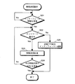
図12には、本実施形態に係る無線ネットワーク10内に含まれている無線通信装置が情報送信を行うときの処理手順をフローチャートの形式で示している。この処理手順は、実際には、制御部57が所定のプログラム・コードを実行するという形態で実現される。
【0118】
まず、無線通信装置のインターフェース部が接続されるソースからの情報を受理したか判断する(ステップS21)。
【0119】
情報を受理した場合には、判断ブロックS21のYESの分岐から次ステップS22に進んで、さらに無線ネットワークが動作中であるか判断する。そして、動作中であれば、タイミング基準パルスに基づいて情報送信処理を行なう(ステップS23)。
【0120】
さらに、その情報送信のACKを受信したかを判断し(ステップS24)、受信した場合には、本処理ルーチン全体を終了する。
【0121】
また、ACKを受信しなければ、ステップS22に移行して、再度ネットワークの動作を確認して、情報送信処理を行なう。
【0122】
また、ステップS22において、無線ネットワークが動作中でないと判断された場合には、NOの分岐よりステップS25に進んで、送信が不可能であったことをインターフェースへ通知し、本処理ルーチン全体を終了する。
【0123】
また、図13には、本実施形態に係る無線ネットワーク10内に含まれている無線通信装置が情報受信を行うときの処理手順をフローチャートの形式で示している。この処理手順は、実際には、制御部67が所定のプログラム・コードを実行するという形態で実現される。
【0124】
まず、無線ネットワークが動作中であるか判断する(ステップS31)。そして、動作中であれば、YESの分岐より次ステップS32に進んで、タイミング基準パルスの後に所定の受信ウインドウを設けて、情報受信処理を行なう。
【0125】
情報受信後、自局宛ての情報を受信したかを判断する(ステップS33)。そして、自局宛て情報の受信があった場合には、当該判断ブロックのYESの分岐より次ステップS34に移行して、その情報のACKを返信する。
【0126】
さらに、受信した情報をインターフェースに供給して、無線通信装置のインターフェース部が接続されるディスティネーションとなる装置(図示せず)へ情報を出力して(ステップS35)、本処理ルーチン全体を終了する。
【0127】
他方、ステップS33において、自局あての情報受信がないと判断された場合、並びに、ステップS31において、無線ネットワークが動作中でないと判断された場合には、その都度、本処理を抜ける。
【0128】
[追補]
以上、特定の実施形態を参照しながら、本発明について詳解してきた。しかしながら、本発明の要旨を逸脱しない範囲で当業者が該実施形態の修正や代用を成し得ることは自明である。すなわち、例示という形態で本発明を開示してきたのであり、本明細書の記載内容を限定的に解釈するべきではない。本発明の要旨を判断するためには、冒頭に記載した特許請求の範囲の欄を参酌すべきである。
【0129】
【発明の効果】
以上詳記したように、本発明によれば、制御局となる装置を特に配置せずに非同期無線通信を行なうことができる、優れた無線通信システム及び無線通信方法、無線ネットワーク形成装置、無線送信装置及び無線送信方法、並びに無線受信装置及び無線受信方法を提供することができる。
【0130】
また、本発明によれば、伝送路の利用状態を把握するためのキャリア検出が困難な無線通信環境下であっても非同期通信を行なうことができる、優れた無線通信システム及び無線通信方法、無線ネットワーク形成装置、無線送信装置及び無線送信方法、並びに無線受信装置及び無線受信方法を提供することができる。
【0131】
また、本発明によれば、UWB(Ultra Wide Band)のようなキャリア検出が困難な無線通信方式を用いて、無線伝送路の利用効率の高い非同期通信を行なうことができる、優れた無線通信システム及び無線通信方法、無線ネットワーク形成装置、無線送信装置及び無線送信方法、並びに無線受信装置及び無線受信方法を提供することができる。
【図面の簡単な説明】
【図1】本発明の一実施形態に係る無線ネットワーク10の構成を模式的に示した図である。
【図2】図1に示した無線ネットワーク10における、各無線通信装置101〜107間の接続関係を示した図である。
【図3】タイミング発生装置100が発生するタイミング基準信号によって無線ネットワーク10内の各無線通信装置100による通信動作を制御する様子を示したチャートである。
【図4】本実施形態に係る無線ネットワーク10に適用されるタイミング発生装置100の機能構成を模式的に示した図である。
【図5】本実施形態に係る無線ネットワーク10内で非同期無線通信を行なうことができる無線送信装置の機能構成を模式的に示した図である。
【図6】本実施形態に係る無線ネットワーク10内で非同期無線通信を行なうことができる無線受信装置の機能構成を模式的に示した図である。
【図7】本実施形態における無線ネットワーク10内での無線通信シーケンスを模式的に示した図である。
【図8】本実施形態に係る無線ネットワーク10内で、無線通信に利用される情報(データ・フレーム)の構成例を示した図である。
【図9】タイミング発生装置100によるタイミング基準パルスを使用しないで非同期無線通信を行なう場合の情報(データ・フレーム)の構成例を示した図である。
【図10】本実施形態に係る無線ネットワーク10内で動作するタイミング発生装置100が実行する動作手順を示したフローチャートである。
【図11】本実施形態に係る無線ネットワーク10内に含まれている無線通信装置のネットワーク動作をフローチャートである。
【図12】本実施形態に係る無線ネットワーク10内に含まれている無線通信装置が情報送信を行うときの処理手順を示したフローチャートである。
【図13】本実施形態に係る無線ネットワーク10内に含まれている無線通信装置が情報受信を行うときの処理手順を示したフローチャートである。
【符号の説明】
10…無線ネットワーク
41…動作スイッチ,42…基準パルス発生器
43…制御部,44…パルス送信部
45…アンテナ
51…インターフェース
52…インターフェース・バッファ
53…無線バッファ,54…無線送信部
55…アンテナ,56…パルス受信部
57…制御部,58…情報記憶部
61…インターフェース
62…インターフェース・バッファ
63…無線バッファ,64…無線受信部
65…アンテナ,66…パルス受信部
67…制御部,68…情報記憶部
100…タイミング発生装置
101,102…無線通信装置[0001]
BACKGROUND OF THE INVENTION
The present invention relates to a radio communication system and a radio communication method, a radio network forming apparatus, a radio transmission apparatus and a radio transmission method, and a radio reception apparatus and a radio reception method that communicate with each other between a plurality of radio stations. The present invention relates to a wireless communication system and a wireless communication method for performing asynchronous wireless communication without particularly arranging a device serving as a station, a wireless network forming device, a wireless transmission device and a wireless transmission method, and a wireless reception device and a wireless reception method.
[0002]
More specifically, the present invention relates to a wireless communication system, a wireless communication method, a wireless network formation apparatus, a wireless transmission apparatus, and a wireless communication that perform asynchronous communication in a wireless communication environment in which carrier detection is difficult to grasp the use state of a transmission path. BACKGROUND OF THE INVENTION 1. Field of the Invention The present invention relates to a transmission method, a wireless reception device, and a wireless reception method, and in particular, wireless that performs asynchronous communication with high utilization efficiency of a wireless transmission path using a wireless communication method such as UWB (Ultra Wide Band) that makes carrier detection difficult. The present invention relates to a communication system and a wireless communication method, a wireless network forming device, a wireless transmission device and a wireless transmission method, and a wireless reception device and a wireless reception method.
[0003]
[Prior art]
As computers become more sophisticated, multiple computers can be connected to form a LAN (Local Area Network) to share information such as files and data, or to share peripheral devices such as printers, Exchange of information such as mail and data transfer is actively performed.
[0004]
In the conventional LAN, each computer is connected by wire using an optical fiber, a coaxial cable, or a twisted pair cable. However, in such a wired LAN, construction for connection is necessary, and it is difficult to construct the LAN easily, and the cable becomes complicated. In addition, even after LAN construction, the movement range of devices is limited by the cable length, which is inconvenient.
[0005]
Therefore, wireless LANs are attracting attention as a system for releasing users from conventional wired LAN wiring. According to this type of wireless LAN, since most of the wired cables can be omitted in a work space such as an office, a communication terminal such as a personal computer (PC) can be moved relatively easily.
[0006]
In recent years, the demand for wireless LAN systems has increased remarkably with the increase in speed and cost. In particular, recently, in order to establish a small-scale wireless network between a plurality of electronic devices existing around a person and perform information communication, introduction of a personal area network (PAN) has been studied.
[0007]
In a small-scale wireless network composed of a relatively small number of clients located in the vicinity, any terminal can perform asynchronous wireless communication directly without using a specific access point. -hoc) Communication "seems to be appropriate.
[0008]
Further, when performing asynchronous communication in these small-scale wireless networks, it is common to adopt a CSMA / CA (Carrier Sense Multiple Access with Collision Avoidance) method for the access control. .
[0009]
The CSMA / CD method is a method of detecting the presence or absence of collision with information transmission of other communication devices by receiving a signal transmitted by itself (Collision Detection), and is mainly used in wired communication. Yes. On the other hand, since it is difficult to receive a signal transmitted by wireless communication by itself, it is confirmed that there is no information transmitted by another communication device by the CDMA / CA method, and then the information transmission is performed. Avoid collisions by starting. According to such an access control method, a plurality of terminals can share the same wireless transmission path and communicate with each other (Multiple Access).
[0010]
Here, as a method for detecting a carrier on a wireless transmission path, a mechanism using a specific frequency carrier is generally employed.
[0011]
In addition, in a wireless communication system in which each terminal constituting a wireless network performs asynchronous wireless communication, information on the preamble signal is received in order for the receiving terminal to successfully receive the wireless signal transmitted from the transmitting terminal. A method of adding and transmitting before transmission is widely used. That is, the transmitting terminal transmits a preamble signal, and the receiving terminal receives the preamble signal, and synchronization is established between the terminals.
[0012]
By the way, recently, high-speed wireless transmission technology has been studied and developed, and one example is a system called UWB (ultra wide band). This is a wireless communication system that realizes high-speed data transmission by using a very high frequency band of 2 GHz to 6 GHz, for example, and performing transmission and reception by spreading data in an extremely wide frequency band of about several GHz.
[0013]
In UWB, an information signal is configured using an impulse signal sequence having a very short period of about several hundred picoseconds, and this signal sequence is transmitted and received. The occupied bandwidth is a bandwidth on the order of GHz such that a value obtained by dividing the occupied bandwidth by its center frequency (for example, 1 GHz to 10 GHz) is approximately 1, and is a so-called W-CDMA, cdma2000 system, and SS (Spread Spectrum). ) And a bandwidth that is normally used in a wireless LAN using an OFDM (Orthogonal Frequency Division Multiplexing) method, the bandwidth is extremely wide.
[0014]
The impulse signal sequence used in the UWB wireless communication system does not have a specific frequency carrier. That is, since there is no signal component in a specific frequency carrier, it is difficult to perform carrier sense.
[0015]
For this reason, there exists a problem that the CSMA / CA system widely used for the conventional radio | wireless communications system cannot be applied to UWB radio | wireless communication as it is.
[0016]
In addition, in wireless communication using the UWB wireless communication technology, in order to receive an asynchronously transmitted signal, it is necessary to detect the presence or absence of the signal over a very long time.
[0017]
In wireless communication using the UWB wireless communication technology, there is no carrier as in conventional wireless communication. For this reason, in order for the receiving terminal to acquire the initial synchronization of the information signal by detecting the presence / absence of the signal, a preamble signal with higher redundancy than in the past must be added before information transmission.
[0018]
[Problems to be solved by the invention]
An object of the present invention is to provide an excellent radio communication system and radio communication method, radio network forming apparatus, radio transmission apparatus and radio transmission method capable of performing asynchronous radio communication without particularly arranging a device serving as a control station, and It is an object of the present invention to provide a wireless reception device and a wireless reception method.
[0019]
A further object of the present invention is to provide an excellent wireless communication system, wireless communication method, and wireless network capable of performing asynchronous communication even in a wireless communication environment in which carrier detection for grasping the utilization state of a transmission path is difficult. The present invention provides a forming apparatus, a wireless transmission apparatus, a wireless transmission method, a wireless reception apparatus, and a wireless reception method.
[0020]
A further object of the present invention is to provide an excellent wireless communication system capable of performing asynchronous communication with high utilization efficiency of a wireless transmission path by using a wireless communication method such as UWB (Ultra Wide Band) in which carrier detection is difficult. A wireless communication method, a wireless network forming device, a wireless transmission device, a wireless transmission method, a wireless reception device, and a wireless reception method are provided.
[0021]
[Means and Actions for Solving the Problems]
The present invention has been made in consideration of the above problems, and the first aspect of the present invention is as follows. Does not have relationship between control station and controlled station Multiple wireless communication devices Consist of A wireless communication system,
A timing generator that transmits a reference pulse signal at a predetermined time interval is arranged, and a wireless network is constructed by wireless communication devices that are within the reach of the reference pulse signal.
This is a wireless communication system.
[0022]
However, “system” here refers to a logical collection of a plurality of devices (or functional modules that realize specific functions), and each device or functional module is in a single housing. It does not matter whether or not.
[0023]
According to the first aspect of the present invention, a wireless network based on ad hoc communication in which each wireless communication device directly communicates with each other within the reach of the reference pulse signal only by arranging a timing generator for supplying the reference pulse signal. Can be built easily. In addition, by setting the reach range of the reference pulse signal as the range of the wireless network, the range of the wireless network can be easily specified.
[0024]
In addition, each wireless communication device that has received the timing signal can perform synchronization processing based on the reference pulse signal, and can perform transmission / reception timing control based on the reference pulse signal. Therefore, in the wireless network, it is possible to easily control asynchronous communication between wireless communication devices.
[0025]
Further, the timing generator may start and / or stop transmission of the reference pulse signal in response to a user operation. In such a case, it is possible to easily construct a wireless network in the reach range of the reference pulse signal only in a desired period in which the reference pulse signal is transmitted according to a user operation.
[0026]
The timing generator may generate a reference pulse signal having a unique pattern. In such a case, each wireless communication device that has received the reference pulse signal can detect where the wireless network device has entered by decoding the pattern of the received reference pulse signal. Of course, one wireless communication device may simultaneously enter two or more adjacent wireless networks. In this case, the operation on each wireless network can be detected based on the unique pattern of the reference pulse signal.
[0027]
In addition, UWB (Ultra Wide Band) wireless communication that receives and transmits a reference pulse signal from a timing generator and spreads data in an extremely wide frequency band and transmits / receives data is performed. You may do it.
[0028]
Since the impulse signal sequence used in the UWB wireless communication system does not have a specific frequency carrier, it is difficult to perform carrier sense, and the CSMA / CA system cannot be applied to UWB wireless communication as it is. In addition, in order to receive an asynchronous signal in UWB wireless communication, a highly redundant preamble signal must be added before information transmission.
[0029]
On the other hand, according to the present invention, each wireless communication device can acquire synchronization based on the reference timing signal received from the timing generator. Therefore, even in UWB wireless communication, redundancy is obtained for initial synchronization acquisition. It is not necessary to add a high preamble signal before information transmission. Therefore, high-speed asynchronous wireless communication can be realized by applying the access control method according to the present invention to UWB wireless communication.
[0030]
The second aspect of the present invention is Does not have relationship between control station and controlled station Multiple wireless communication devices Consist of A network forming apparatus for constructing a wireless network,
Each wireless communication device in the wireless network performs synchronization processing Or Signal generating means for generating a reference pulse signal for generating a reference pulse signal at a predetermined time interval for use in transmission / reception timing control; and
Signal transmitting means for transmitting the generated reference pulse signal;
A network forming apparatus.
[0031]
Each wireless communication device that has received the reference pulse signal from the network forming device according to the second aspect of the present invention performs synchronization processing based on the reference pulse signal, and performs transmission / reception timing control based on the reference pulse signal. As a result, asynchronous communication between the wireless communication devices can be easily realized.
[0032]
Therefore, by arranging the network forming device according to the second aspect of the present invention, a wireless network based on ad hoc communication in which each wireless communication device directly communicates can be constructed. In addition, by setting the reach range of the reference pulse signal as the range of the wireless network, the range of the wireless network can be easily specified.
[0033]
The network forming apparatus may generate a reference pulse signal having a unique pattern. In such a case, each wireless communication device that has received the reference pulse signal can detect where the wireless network device has entered by decoding the pattern of the received reference pulse signal. Of course, one wireless communication device may simultaneously enter two or more adjacent wireless networks. In this case, the operation on each wireless network can be detected based on the unique pattern of the reference pulse signal.
[0034]
In addition, UWB (Ultra Wide Band) wireless communication that receives and transmits a reference pulse signal from a network forming apparatus and spreads data in an extremely wide frequency band and performs transmission / reception is performed. You may do it. That is, each wireless communication device can acquire synchronization in the network based on the reference pulse signal received from the network forming device. Therefore, in UWB wireless communication, a highly redundant preamble signal is used to acquire initial synchronization. Need not be added before information transmission. Therefore, high-speed asynchronous wireless communication by UWB wireless communication can be realized only by arranging the network forming apparatus according to the present invention.
[0035]
The network forming apparatus according to the second aspect of the present invention may further include user input means for accepting a user operation. In addition, the signal transmission unit may start and / or stop transmission of the reference pulse signal in response to a user operation via the user input unit. In such a case, it is possible to easily construct a wireless network in the reach range of the reference pulse signal only in a desired period in which the reference pulse signal is transmitted according to a user operation.
[0036]
The third aspect of the present invention is Does not have a specific control station A wireless transmission device or a wireless transmission method that operates in a wireless network,
Means or step for receiving a reference pulse signal transmitted from a predetermined network forming device;
Means or steps for initiating transmission of information based on the received reference pulse signal;
A wireless transmission device or a wireless transmission method.
[0037]
The radio transmission apparatus or radio transmission method according to the third aspect of the present invention performs a synchronization process based on the reference pulse signal or performs a transmission timing control based on the reference pulse signal, thereby Asynchronous communication with can be easily realized.
[0038]
In addition, the wireless transmission device or the wireless transmission method according to the third aspect of the present invention performs the network operation only during the period in which the reference pulse signal is received.
[0039]
Therefore, according to the wireless transmission device or the wireless transmission method according to the third aspect of the present invention, by entering the wireless transmission device in the reach range of the reference pulse signal, the wireless transmission device can enter the wireless network and perform asynchronous wireless communication using ad hoc communication. Transmission can be easily performed.
[0040]
In addition, the reach of the reference pulse signal is the range of the wireless network, but the wireless transmitter can display the network operation in response to the reception of the reference pulse signal, thereby facilitating the range of the wireless network. Can be identified.
[0041]
The network forming apparatus may generate a reference pulse signal having a unique pattern. In such a case, the wireless transmission device according to the present invention can detect where the wireless network device has entered by decoding the pattern of the received reference pulse signal. Of course, one wireless communication device may simultaneously enter two or more adjacent wireless networks. In this case, the operation on each wireless network can be detected based on the unique pattern of the reference pulse signal. Moreover, you may make it switch the display of network operation | movement according to the wireless network which entered.
[0042]
In addition, since the wireless transmission device or the wireless transmission method according to the third aspect of the present invention can acquire synchronization based on the reference timing signal received from the network forming device, initial synchronization acquisition is also possible in UWB wireless communication. Therefore, it is not necessary to add a highly redundant preamble signal before information transmission.
[0043]
The fourth aspect of the present invention is Does not have a specific control station A wireless reception device or a wireless reception method that operates in a wireless network,
Means or step for receiving a reference pulse signal transmitted from a predetermined network forming device;
Means or steps for initiating reception of information based on the received reference pulse signal;
A wireless reception device or a wireless reception method.
[0044]
The radio reception apparatus or radio reception method according to the fourth aspect of the present invention provides a radio transmission apparatus by performing synchronization processing based on the reference pulse signal or performing reception timing control based on the reference pulse signal. Asynchronous communication with can be easily realized.
[0045]
In addition, the radio reception apparatus or radio reception method according to the fourth aspect of the present invention performs network operation only during a period in which the reference pulse signal is received.
[0046]
Therefore, according to the wireless reception device or the wireless reception method according to the fourth aspect of the present invention, the wireless reception device is placed in the reach range of the reference pulse signal, thereby entering the wireless network and performing asynchronous wireless communication by ad hoc communication. Transmission can be easily performed.
[0047]
Also, the reach of the reference pulse signal is the range of the wireless network, but the wireless receiver can display the network operation in response to the reception of the reference pulse signal, thereby facilitating the range of the wireless network. Can be identified.
[0048]
The network forming apparatus may generate a reference pulse signal having a unique pattern. In such a case, the wireless receiving apparatus according to the present invention can detect where the wireless network device has entered by decoding the pattern of the received reference pulse signal. Of course, one wireless communication device may simultaneously enter two or more adjacent wireless networks. In this case, the operation on each wireless network can be detected based on the unique pattern of the reference pulse signal. Moreover, you may make it switch the display of network operation | movement according to the wireless network which entered.
[0049]
In addition, since the wireless reception device can acquire synchronization based on the reference timing signal received from the network forming device, in UWB wireless communication, a highly redundant preamble signal is transmitted for information transmission in order to acquire initial synchronization. There is no need to prepend.
[0050]
Other objects, features, and advantages of the present invention will become apparent from more detailed description based on embodiments of the present invention described later and the accompanying drawings.
[0051]
DETAILED DESCRIPTION OF THE INVENTION
Hereinafter, embodiments of the present invention will be described in detail with reference to the drawings.
[0052]
FIG. 1 schematically shows the configuration of a
[0053]
Each of the
[0054]
The wireless communication unit is installed in the computer system main body by a network interface card (NIC) such as an adapter card or a PC card. The wireless communication can be realized by the cooperative operation of the wireless communication unit driving software and the wireless communication unit activated on the computer system.
[0055]
As shown in FIG. 1, in the present embodiment, one timing generator 100 is arranged in one
[0056]
Here, assuming that the timing reference pulse signal from the timing generator 100 propagates to a region indicated by a broken line in the figure, all the wireless communication devices 101 to 107 described here receive at the same timing. It is in a state where can be.
[0057]
FIG. 2 illustrates the connection relationship between the wireless communication apparatuses 101 to 107 in the
[0058]
In the figure, the wireless communication apparatus 101 is located relatively close to the
[0059]
Further, since the
[0060]
In addition, since the
[0061]
Further, since the
[0062]
Further, since the
[0063]
In addition, since the
[0064]
In addition, since the
[0065]
FIG. 3 shows an example of operation control of asynchronous wireless communication in the
[0066]
In the present embodiment, the wireless communication devices 101 to 107 form a network based on the timing reference signal generated by the timing generation device 100, and perform asynchronous information transmission with other wireless communication devices existing in the vicinity. it can.
[0067]
In the example shown in the figure, information is transmitted from the wireless communication apparatus 101 by the first timing reference pulse, and the
[0068]
Further, since information transmission is performed based on the timing reference pulse from the timing generator 100, each of the wireless communication devices 100 to 107 constituting the
[0069]
FIG. 4 schematically shows a functional configuration of the timing generator 100 applied to the
[0070]
By operating the
[0071]
Each of the
[0072]
Therefore, by arranging the timing device 100, it is possible to easily construct the
[0073]
Further, the timing generator 100 may generate a reference pulse signal having a unique pattern. In such a case, each
[0074]
In addition, UWB (Ultra Wide Band) wireless communication that receives and transmits a reference pulse signal from the timing generator 100 and spreads data in an extremely wide frequency band and transmits / receives data between the wireless communication devices incorporated in the wireless network. You may make it perform. That is, since each wireless communication device can acquire synchronization based on the reference pulse signal received from the timing generation device 100, in UWB wireless communication, a highly redundant preamble signal is used for information acquisition in order to acquire initial synchronization. There is no need to add it before sending. Therefore, high-speed asynchronous wireless communication by UWB wireless communication can be realized only by arranging the timing generator 100.
[0075]
Further, the timing generator 100 starts and / or stops transmission of the reference pulse signal in response to the user operating the
[0076]
FIG. 5 schematically illustrates a functional configuration of a wireless transmission unit (hereinafter, also simply referred to as “wireless transmission device”) of a wireless communication device capable of performing asynchronous wireless communication in the
[0077]
As shown in the figure, this wireless transmission device includes an interface 51, an interface buffer 52, a wireless buffer 53, a wireless transmission unit 54, an antenna 55, a
[0078]
The interface 51 is connected to an information source such as a computer system main body, receives predetermined information, and temporarily stores the information in the interface buffer 52. When information for transmission is read from the interface buffer 52, it is further temporarily stored in the wireless buffer 53, and a preamble and header information for wireless transmission are added.
[0079]
In addition, when the timing reference pulse signal transmitted from the timing generator 100 is received by the antenna 55, it is decoded by the
[0080]
The operation of the wireless transmission device is comprehensively controlled by the
[0081]
This wireless transmission device can easily realize asynchronous communication with other devices by performing synchronization processing based on the reference pulse signal and performing transmission timing control based on the reference pulse signal. Further, the wireless transmission device performs network operation only during a period in which the reference pulse signal is received. Therefore, by arranging the wireless transmission device in the reach range of the reference pulse signal, it is possible to enter the wireless network and easily perform asynchronous wireless transmission by ad hoc communication.
[0082]
The wireless transmission device may further include a network operation display unit (not shown) that displays the network operation in response to receiving the reference pulse signal. In such a case, the user can easily specify the range of the wireless network based on the display of the network operation. When the timing generator 100 generates a reference pulse signal having a unique pattern, the
[0083]
In addition, since the wireless transmission device can acquire synchronization based on the reference timing signal received from the timing generation device 100, in UWB wireless communication, a highly redundant preamble signal is transmitted to acquire initial synchronization. There is no need to add it before.
[0084]
FIG. 6 schematically illustrates a functional configuration of a wireless reception unit (hereinafter, also simply referred to as “wireless reception device”) of a wireless communication device capable of performing asynchronous wireless communication in the
[0085]
As shown in the figure, this radio receiving apparatus includes an interface 61, an interface buffer 62, a radio buffer 63, a radio receiving unit 64, an antenna 65, a
[0086]
When the wireless receiver receives the timing reference pulse signal transmitted from the timing generator 100 with the antenna 65, the wireless receiver decodes it with the
[0087]
Since information may be sent immediately after receiving the timing reference pulse, a reception window (described later) is set at that timing, and the radio reception unit 64 is operated to perform reception.
[0088]
Further, it is determined whether the signal received by the wireless reception unit 64 is information addressed to the own wireless reception device. If the information is addressed to the own wireless reception device, the information is stored in the wireless buffer 63 and only necessary information is stored in the interface buffer. 62.
[0089]
Information is sequentially supplied via the interface 61 to information destinations (for example, a computer system: not shown) connected to the wireless reception device.
[0090]
The operation of the wireless reception device is comprehensively controlled by the
[0091]
This wireless reception device can easily realize asynchronous communication with other devices by performing synchronization processing based on the reference pulse signal or performing reception timing control based on the reference pulse signal. Further, the wireless reception apparatus performs network operation only during a period in which the reference pulse signal is received. Therefore, by arranging the wireless receiver in the reach range of the reference pulse signal, it is possible to enter the wireless network and easily perform asynchronous wireless transmission by ad hoc communication.
[0092]
The wireless reception device may further include a network operation display unit (not shown) that displays the network operation in response to receiving the reference pulse signal. In such a case, the user can easily specify the range of the wireless network based on the display of the network operation. When the timing generator 100 generates a reference pulse signal having a unique pattern, the
[0093]
In addition, since the wireless reception device can acquire synchronization based on the reference timing signal received from the timing generation device 100, in UWB wireless communication, a highly redundant preamble signal is transmitted to acquire initial synchronization. There is no need to add it before.
[0094]
In this specification, the wireless transmission device and the wireless reception device are described separately in FIG. 5 and FIG. 6, respectively, but actually configured as a wireless communication device having both a wireless transmission function and a wireless reception function. It is also possible.
[0095]
FIG. 7 schematically shows a wireless communication sequence in the
[0096]
As shown in the figure, the timing generator 100 periodically generates reference pulses at predetermined time intervals. The communication device serving as the information transmission source transmits the asynchronous transmission information to the communication device on the information receiving side based on the reference pulse.
[0097]
Further, the communication device on the information receiving side transmits ACK information indicating receipt confirmation of asynchronous information transmission to the communication device that is the information transmission source based on the reference pulse.
[0098]
FIG. 8 shows a configuration example of information (data frame) used for wireless communication in the
[0099]
The timing reference pulse (T) periodically transmitted from the timing generator 100 is composed of a signal train having a short pulse shape.
[0100]
Asynchronous transmission information transmitted from a communication device on the information transmission side has a preamble (P) and an information header (H) added as a redundant part to payload information which is a transmission data body.
[0101]
Also, the ACK information transmitted from the communication device on the information receiving side is composed of short ACK information with a preamble (P) added as a redundant part.
[0102]
A reception window is set for each of the communication devices on the wireless transmission side and the wireless reception side.
[0103]
Since the impulse signal sequence used in the UWB wireless communication system does not have a specific frequency carrier, it is difficult to perform carrier sense, and the CSMA / CA system cannot be applied to UWB wireless communication as it is. In addition, in order to receive an asynchronous signal in UWB wireless communication, a highly redundant preamble signal must be added before information transmission.
[0104]
On the other hand, according to the present embodiment, each wireless communication device can acquire synchronization in the network based on the reference timing signal received from the timing generator 100. Therefore, even in UWB wireless communication, initial synchronization acquisition is possible. Therefore, it is not necessary to add a highly redundant preamble signal before information transmission. Therefore, high-speed asynchronous wireless communication can be realized by applying the access control method according to the present invention to UWB wireless communication.
[0105]
For comparison with FIG. 8, FIG. 9 shows a configuration example of information (data frame) when asynchronous wireless communication is performed without using the timing reference pulse by the timing generator 100.
[0106]
Information in the case of performing asynchronous wireless transmission is composed of payload information in which an information header (H) is added as a redundant portion together with a redundant preamble. On the other hand, the ACK information transmitted from the communication device on the information receiving side is also composed of short ACK information to which a redundant preamble is added.
[0107]
In general, a redundant preamble is added in this way, which is a cause of a decrease in transmission path utilization efficiency.
[0108]
In addition, the communication device on the information receiving side may send information asynchronously without preparing in advance. Therefore, it is necessary to always monitor the wireless transmission path and perform reception processing. It is difficult to reduce power consumption.
[0109]
FIG. 10 shows, in the form of a flowchart, an operation procedure executed by the timing generator 100 that operates in the
[0110]
First, it is confirmed whether the
[0111]
If the
[0112]
If the
[0113]
FIG. 11 shows a network operation of the wireless communication apparatus included in the
[0114]
When starting the operation, the wireless communication device first operates the reception function to receive the reference pulse from the timing generator 100 (step S11).
[0115]
Next, it is determined whether or not a reference pulse signal has been received (step S12), and if received, the wireless communication device enters a wireless network defined by the timing generator 100. In this case, the operation as a communication device of the
[0116]
On the other hand, when the reference pulse signal cannot be received for a predetermined time, the
[0117]
FIG. 12 shows a processing procedure when the wireless communication apparatus included in the
[0118]
First, it is determined whether information from a source to which the interface unit of the wireless communication apparatus is connected has been received (step S21).
[0119]
If the information is accepted, the process proceeds from the YES branch of the decision block S21 to the next step S22 to further determine whether the wireless network is operating. If it is in operation, information transmission processing is performed based on the timing reference pulse (step S23).
[0120]
Further, it is determined whether or not the information transmission ACK has been received (step S24). If received, the entire processing routine is terminated.
[0121]
If ACK is not received, the process proceeds to step S22, where the operation of the network is confirmed again, and information transmission processing is performed.
[0122]
If it is determined in step S22 that the wireless network is not in operation, the process advances from step NO to step S25 to notify the interface that transmission is impossible, and the entire processing routine is terminated. To do.
[0123]
FIG. 13 shows a processing procedure when the wireless communication apparatus included in the
[0124]
First, it is determined whether the wireless network is operating (step S31). If it is in operation, the process proceeds from the YES branch to the next step S32, where a predetermined reception window is provided after the timing reference pulse to perform information reception processing.
[0125]
After receiving the information, it is determined whether information addressed to the own station has been received (step S33). If the information addressed to the own station is received, the process proceeds to the next step S34 from the YES branch of the determination block, and an ACK of the information is returned.
[0126]
Further, the received information is supplied to the interface, and the information is output to a destination device (not shown) to which the interface unit of the wireless communication device is connected (step S35), and the entire processing routine is terminated. .
[0127]
On the other hand, if it is determined in step S33 that there is no reception of information addressed to the own station, and if it is determined in step S31 that the wireless network is not in operation, the present process is exited.
[0128]
[Supplement]
The present invention has been described in detail above with reference to specific embodiments. However, it is obvious that those skilled in the art can make modifications and substitutions of the embodiment without departing from the gist of the present invention. That is, the present invention has been disclosed in the form of exemplification, and the contents described in the present specification should not be interpreted in a limited manner. In order to determine the gist of the present invention, the claims section described at the beginning should be considered.
[0129]
【The invention's effect】
As described in detail above, according to the present invention, an excellent wireless communication system and wireless communication method, wireless network forming apparatus, wireless transmission capable of performing asynchronous wireless communication without particularly arranging a device serving as a control station. An apparatus, a wireless transmission method, a wireless reception apparatus, and a wireless reception method can be provided.
[0130]
Furthermore, according to the present invention, an excellent wireless communication system and wireless communication method, wireless communication capable of performing asynchronous communication even in a wireless communication environment in which carrier detection for grasping the utilization state of a transmission path is difficult A network forming device, a wireless transmission device, a wireless transmission method, a wireless reception device, and a wireless reception method can be provided.
[0131]
In addition, according to the present invention, an excellent wireless communication system capable of performing asynchronous communication with high utilization efficiency of a wireless transmission path by using a wireless communication method such as UWB (Ultra Wide Band) in which carrier detection is difficult. And a wireless communication method, a wireless network forming device, a wireless transmission device and a wireless transmission method, and a wireless reception device and a wireless reception method.
[Brief description of the drawings]
FIG. 1 is a diagram schematically showing a configuration of a
2 is a diagram showing a connection relationship between wireless communication apparatuses 101 to 107 in the
FIG. 3 is a chart showing a state in which a communication operation by each wireless communication device 100 in the
FIG. 4 is a diagram schematically illustrating a functional configuration of a timing generation device 100 applied to a
FIG. 5 is a diagram schematically illustrating a functional configuration of a wireless transmission device capable of performing asynchronous wireless communication within the
FIG. 6 is a diagram schematically illustrating a functional configuration of a wireless reception device capable of performing asynchronous wireless communication in the
FIG. 7 is a diagram schematically showing a wireless communication sequence in the
FIG. 8 is a diagram showing a configuration example of information (data frame) used for wireless communication in the
9 is a diagram showing a configuration example of information (data frame) when asynchronous wireless communication is performed without using a timing reference pulse by the timing generation device 100. FIG.
FIG. 10 is a flowchart showing an operation procedure executed by the timing generator 100 operating in the
FIG. 11 is a flowchart showing the network operation of the wireless communication device included in the
FIG. 12 is a flowchart showing a processing procedure when the wireless communication device included in the
FIG. 13 is a flowchart showing a processing procedure when a wireless communication device included in the
[Explanation of symbols]
10. Wireless network
41 ... Operation switch, 42 ... Reference pulse generator
43 ... Control unit, 44 ... Pulse transmission unit
45 ... Antenna
51 ... Interface
52 ... Interface buffer
53 ... Wireless buffer, 54 ... Wireless transmitter
55 ... antenna, 56 ... pulse receiver
57 ... Control unit, 58 ... Information storage unit
61 ... Interface
62: Interface buffer
63 ... wireless buffer, 64 ... wireless receiver
65 ... antenna, 66 ... pulse receiver
67 ... Control unit, 68 ... Information storage unit
100: Timing generator
101, 102 ... Wireless communication apparatus
Claims (16)
所定の時間間隔で基準パルス信号を送信するタイミング発生装置と、
前記タイミング発生装置が送信する基準パルス信号の到達範囲に基づいて特定される無線ネットワークと、
前記タイミング発生装置から送信される基準パルス信号を受信するパルス受信手段と、他の無線通信装置との間で無線データ信号を送受信する無線通信手段を備え、前記無線ネットワーク内で基準パルス信号を受信している期間のみネットワーク動作を行ない、前記パルス受信手段で受信した基準パルス信号に基づいて互いに送受信タイミングを制御しながら前記無線通信手段を用いて他の無線通信装置と無線通信を行なう複数の無線通信装置と、
を具備することを特徴とする無線通信システム。 A wireless communication system comprising a plurality of wireless communication devices that perform direct communication ,
A timing generator for transmitting a reference pulse signal at a predetermined time interval ;
A wireless network identified based on a reach of a reference pulse signal transmitted by the timing generator;
A pulse receiving means for receiving a reference pulse signal transmitted from the timing generator and a wireless communication means for transmitting / receiving a wireless data signal to / from another wireless communication apparatus, and receiving the reference pulse signal within the wireless network A plurality of radios that perform a network operation only during a period of time and perform radio communication with another radio communication device using the radio communication unit while controlling transmission / reception timing based on a reference pulse signal received by the pulse receiving unit A communication device;
A wireless communication system comprising:
ことを特徴とする請求項1に記載の無線通信システム。 The wireless communication means of each wireless communication device transmits and receives a UWB (Ultra Wide Band) signal in which data is spread over a wide frequency band.
The wireless communication system according to claim 1.
ことを特徴とする請求項1に記載の無線通信システム。 The timing generator starts or stops transmission of a reference pulse signal in response to a user operation.
The wireless communication system according to claim 1.
基準パルス信号を受信した各無線通信装置は、受信した基準パルス信号が持つパターンをデコードすることによって、自分が何処の無線ネットワークに参入しているのかを検知する、
ことを特徴とする請求項1に記載の無線通信システム。Before Symbol timing generator generates a reference pulse signal consisting of unique patterns,
Each wireless communication device that has received the reference pulse signal detects where the wireless network has entered by decoding the pattern of the received reference pulse signal.
The wireless communication system according to claim 1.
前記無線ネットワーク内の各無線通信装置が同期処理又は送受信のタイミング制御に使用するための所定の時間間隔で基準パルス信号を発生する基準パルス信号を発生する信号発生手段と、Signal generating means for generating a reference pulse signal for generating a reference pulse signal at a predetermined time interval for each wireless communication device in the wireless network to use for synchronization processing or transmission / reception timing control;
該発生された基準パルス信号を送信する信号送信手段を備え、Comprising signal transmitting means for transmitting the generated reference pulse signal;
前記信号送信手段が送信する基準パルス信号の到達範囲に基づいて無線ネットワークが特定され、A wireless network is identified based on the reach of a reference pulse signal transmitted by the signal transmission means,
前記の各無線通信装置は、基準パルス信号を受信するパルス受信手段と、他の無線通信装置との間で無線データ信号を送受信する無線通信手段を備え、前記無線ネットワーク内で基準パルス信号を受信している期間のみネットワーク動作を行ない、受信した基準パルス信号に基づいて互いに送受信タイミングを制御しながら前記無線通信手段を用いて他の無線通信手段と無線通信を行なう、Each of the wireless communication devices includes pulse receiving means for receiving a reference pulse signal and wireless communication means for transmitting / receiving a wireless data signal to / from another wireless communication device, and receives the reference pulse signal within the wireless network. Performing network operation only during a period of time, performing wireless communication with other wireless communication means using the wireless communication means while controlling transmission and reception timing based on the received reference pulse signal,
ことを特徴とするネットワーク形成装置。A network forming apparatus.
ことを特徴とする請求項5に記載のネットワーク形成装置。The network forming apparatus according to claim 5.
前記信号送信手段は、前記ユーザ入力手段を介したユーザ操作に応答して基準パルス信号の送信を開始又は停止する、
ことを特徴とする請求項5に記載のネットワーク形成装置。A user input means for receiving a user operation;
The signal transmission means starts or stops transmission of a reference pulse signal in response to a user operation via the user input means;
The network forming apparatus according to claim 5 .
ことを特徴とする請求項5に記載のネットワーク形成装置。The signal generating means generates a reference pulse signal having a unique pattern;
The network forming apparatus according to claim 5 .
前記タイミング発生装置から送信される基準パルス信号を受信するパルス受信手段と、
他の無線通信装置へ無線データ信号を送信する無線送信手段を備え、
前記無線ネットワーク内で基準パルス信号を受信している期間のみネットワーク動作を行ない、前記パルス受信手段で受信した基準パルス信号に基づいて送信タイミングを制御しながら前記無線送信手段を用いて他の無線通信装置への無線データ信号の送信を行なう、
ことを特徴とする無線送信装置。A wireless transmission device that operates in a wireless network in which wireless communication devices directly communicate with each other , the wireless network includes a timing generator that transmits a reference pulse signal at a predetermined time interval, and the timing generator The wireless network is identified based on the reach of the reference pulse signal to be transmitted,
Pulse receiving means for receiving a reference pulse signal transmitted from the timing generator;
A wireless transmission means for transmitting a wireless data signal to another wireless communication device;
Network operation is performed only during a period in which the reference pulse signal is received in the wireless network, and other wireless communication is performed using the wireless transmission unit while controlling transmission timing based on the reference pulse signal received by the pulse receiving unit. Transmit wireless data signals to the device,
A wireless transmitter characterized by the above.
ことを特徴とする請求項9に記載の無線送信装置。 The wireless transmission means transmits a UWB (Ultra Wide Band) signal in which data is spread over a wide frequency band.
The wireless transmission device according to claim 9.
ことを特徴とする請求項9に記載の無線送信装置。 Means for displaying network activity in response to receiving the reference pulse signal;
The wireless transmission device according to claim 9.
前記タイミング発生装置から送信される基準パルス信号を受信するパルス受信ステップと、
該受信した基準パルス信号に基づいて情報の送信を開始するステップと、
を具備することを特徴とする無線送信方法。A wireless transmission method that operates in a wireless network in which wireless communication devices directly communicate with each other , wherein the wireless network includes a timing generator that transmits a reference pulse signal at a predetermined time interval, and the timing generator The wireless network is identified based on the reach of the reference pulse signal to be transmitted,
A pulse receiving step of receiving a reference pulse signal transmitted from the timing generator ;
Starting transmission of information based on the received reference pulse signal;
A wireless transmission method comprising:
前記タイミング発生装置から送信される基準パルス信号を受信するパルス受信手段と、
他の無線通信装置からの無線データ信号を受信する無線受信手段を備え、
前記無線ネットワーク内で基準パルス信号を受信している期間のみネットワーク動作を行ない、前記パルス受信手段で受信した基準パルス信号に基づいて受信タイミングを制御しながら前記無線受信手段を用いて他の無線通信装置からの無線データ信号の受信を行なう、
ことを特徴とする無線受信装置。A wireless reception device that operates in a wireless network in which wireless communication devices directly communicate with each other , the wireless network includes a timing generator that transmits a reference pulse signal at a predetermined time interval, and the timing generator The wireless network is identified based on the reach of the reference pulse signal to be transmitted,
Pulse receiving means for receiving a reference pulse signal transmitted from the timing generator ;
Comprising wireless receiving means for receiving wireless data signals from other wireless communication devices;
Network operation is performed only during a period in which the reference pulse signal is received in the wireless network, and other wireless communication is performed using the wireless reception unit while controlling reception timing based on the reference pulse signal received by the pulse reception unit. Receive wireless data signals from the device,
A wireless receiver characterized by that.
ことを特徴とする請求項13に記載の無線受信装置。 The wireless reception means receives a UWB (Ultra Wide Band) signal obtained by spreading data over a wide frequency band.
The wireless receiver according to claim 13.
ことを特徴とする請求項13に記載の無線受信装置。Means for displaying network activity in response to receiving the reference pulse signal;
The wireless receiver according to claim 13.
前記タイミング発生装置から送信される基準パルス信号を受信するパルス受信ステップと、
該受信した基準パルス信号に基づいて情報の受信を開始するステップと、
を具備することを特徴とする無線受信方法。A wireless reception method that operates in a wireless network in which wireless communication devices directly communicate with each other , wherein the wireless network includes a timing generator that transmits a reference pulse signal at a predetermined time interval, and the timing generator The wireless network is identified based on the reach of the reference pulse signal to be transmitted,
A pulse receiving step of receiving a reference pulse signal transmitted from the timing generator ;
Starting receiving information based on the received reference pulse signal;
A wireless reception method comprising:
Priority Applications (2)
| Application Number | Priority Date | Filing Date | Title |
|---|---|---|---|
| JP2002034573A JP3968506B2 (en) | 2002-02-12 | 2002-02-12 | RADIO COMMUNICATION SYSTEM, NETWORK FORMING DEVICE, RADIO TRANSMITTING DEVICE, RADIO TRANSMITTING METHOD, RADIO RECEIVING DEVICE, AND RADIO RECEIVING METHOD |
| US10/353,510 US7421051B2 (en) | 2002-02-12 | 2003-01-29 | Radio communication system and method, wireless network forming device, radio transmission unit and method, and radio reception unit and method |
Applications Claiming Priority (1)
| Application Number | Priority Date | Filing Date | Title |
|---|---|---|---|
| JP2002034573A JP3968506B2 (en) | 2002-02-12 | 2002-02-12 | RADIO COMMUNICATION SYSTEM, NETWORK FORMING DEVICE, RADIO TRANSMITTING DEVICE, RADIO TRANSMITTING METHOD, RADIO RECEIVING DEVICE, AND RADIO RECEIVING METHOD |
Publications (3)
| Publication Number | Publication Date |
|---|---|
| JP2003234691A JP2003234691A (en) | 2003-08-22 |
| JP2003234691A5 JP2003234691A5 (en) | 2005-08-11 |
| JP3968506B2 true JP3968506B2 (en) | 2007-08-29 |
Family
ID=27777028
Family Applications (1)
| Application Number | Title | Priority Date | Filing Date |
|---|---|---|---|
| JP2002034573A Expired - Fee Related JP3968506B2 (en) | 2002-02-12 | 2002-02-12 | RADIO COMMUNICATION SYSTEM, NETWORK FORMING DEVICE, RADIO TRANSMITTING DEVICE, RADIO TRANSMITTING METHOD, RADIO RECEIVING DEVICE, AND RADIO RECEIVING METHOD |
Country Status (2)
| Country | Link |
|---|---|
| US (1) | US7421051B2 (en) |
| JP (1) | JP3968506B2 (en) |
Families Citing this family (8)
| Publication number | Priority date | Publication date | Assignee | Title |
|---|---|---|---|---|
| JP4173789B2 (en) * | 2003-09-19 | 2008-10-29 | 株式会社キャンパスクリエイト | Node, communication system and communication method using the same |
| JP4409283B2 (en) | 2003-12-26 | 2010-02-03 | 富士通コンポーネント株式会社 | Communication apparatus and communication method |
| JP4239859B2 (en) * | 2004-03-05 | 2009-03-18 | 沖電気工業株式会社 | PPM signal demodulator |
| JP4365293B2 (en) * | 2004-09-02 | 2009-11-18 | パナソニック株式会社 | Transmission method, reception method, transmission / reception method, transmission device, reception device, and transmission / reception device |
| JP4254708B2 (en) * | 2004-12-27 | 2009-04-15 | 沖電気工業株式会社 | Communication timing control device, communication timing control method, node, and communication system |
| US8041347B2 (en) * | 2005-01-21 | 2011-10-18 | Responsive Innovations, Llc | Transmitter controlled communication links |
| US7330716B2 (en) | 2005-01-21 | 2008-02-12 | Responsive Innovations, Llc | Wireless communication system |
| US8913634B2 (en) * | 2005-04-01 | 2014-12-16 | Freescale Semiconductor, Inc. | Method and apparatus facilitating multi mode interfaces |
Family Cites Families (4)
| Publication number | Priority date | Publication date | Assignee | Title |
|---|---|---|---|---|
| GB9304638D0 (en) * | 1993-03-06 | 1993-04-21 | Ncr Int Inc | Wireless data communication system having power saving function |
| JP2002535881A (en) * | 1999-01-13 | 2002-10-22 | コーニンクレッカ フィリップス エレクトロニクス エヌ ヴィ | Wireless local area network (LAN) and method of operating LAN |
| US7221686B1 (en) * | 2001-11-30 | 2007-05-22 | Meshnetworks, Inc. | System and method for computing the signal propagation time and the clock correction for mobile stations in a wireless network |
| US6671525B2 (en) * | 2001-12-13 | 2003-12-30 | Motorola, Inc. | Beacon assisted hybrid asynchronous wireless communications protocol |
-
2002
- 2002-02-12 JP JP2002034573A patent/JP3968506B2/en not_active Expired - Fee Related
-
2003
- 2003-01-29 US US10/353,510 patent/US7421051B2/en not_active Expired - Fee Related
Also Published As
| Publication number | Publication date |
|---|---|
| US20030174779A1 (en) | 2003-09-18 |
| US7421051B2 (en) | 2008-09-02 |
| JP2003234691A (en) | 2003-08-22 |
Similar Documents
| Publication | Publication Date | Title |
|---|---|---|
| EP1199842B1 (en) | Dual mode wireless data communications | |
| JP4407126B2 (en) | Wireless communication system, wireless communication apparatus, wireless communication method, and computer program | |
| JP3849647B2 (en) | Wireless communication system, wireless communication apparatus, wireless communication method, and computer program | |
| EP2296287B1 (en) | Ultra-wideband/low power communication having a dedicated memory stick for fast data downloads-apparatus, systems and methods | |
| JP3885597B2 (en) | Wireless communication system, wireless communication control method, wireless communication apparatus, wireless communication method, and computer program | |
| US5914796A (en) | Communication protocol for half-duplex traffic | |
| CN101667849B (en) | Data transmission method, network equipment and communication system | |
| JP3777155B2 (en) | Wireless communication device capable of improving connection rate and method thereof | |
| JP3968506B2 (en) | RADIO COMMUNICATION SYSTEM, NETWORK FORMING DEVICE, RADIO TRANSMITTING DEVICE, RADIO TRANSMITTING METHOD, RADIO RECEIVING DEVICE, AND RADIO RECEIVING METHOD | |
| JP3828156B2 (en) | Signal transmission between networked computers | |
| JP2003196775A (en) | Meter reader | |
| WO2012082816A2 (en) | Fast access asynchronous repeater wakeup protocol | |
| US7260359B2 (en) | Method for transmission of data between a master station and a slave station, and a data transmission system | |
| JPH11220459A (en) | Radio network system and radio terminal | |
| CN101401354A (en) | Allocation of a communications channel to a data transfer session | |
| EP1233583A2 (en) | Reduced subset scan and dual frequency wakeup for bluetooth inquiry operation | |
| JP2006314121A (en) | Wireless communication system, apparatus, and method, and wireless communication control method | |
| JP4013393B2 (en) | Wireless communication method and apparatus | |
| JP2002335168A (en) | Transmission device and method therefor | |
| JPH08125582A (en) | Radio wave communication method using low-speed frequency hopping system |
Legal Events
| Date | Code | Title | Description |
|---|---|---|---|
| A521 | Request for written amendment filed |
Free format text: JAPANESE INTERMEDIATE CODE: A523 Effective date: 20050127 |
|
| A621 | Written request for application examination |
Free format text: JAPANESE INTERMEDIATE CODE: A621 Effective date: 20050127 |
|
| A977 | Report on retrieval |
Free format text: JAPANESE INTERMEDIATE CODE: A971007 Effective date: 20060920 |
|
| A131 | Notification of reasons for refusal |
Free format text: JAPANESE INTERMEDIATE CODE: A131 Effective date: 20060926 |
|
| A521 | Request for written amendment filed |
Free format text: JAPANESE INTERMEDIATE CODE: A523 Effective date: 20061122 |
|
| TRDD | Decision of grant or rejection written | ||
| A01 | Written decision to grant a patent or to grant a registration (utility model) |
Free format text: JAPANESE INTERMEDIATE CODE: A01 Effective date: 20070508 |
|
| A61 | First payment of annual fees (during grant procedure) |
Free format text: JAPANESE INTERMEDIATE CODE: A61 Effective date: 20070521 |
|
| FPAY | Renewal fee payment (event date is renewal date of database) |
Free format text: PAYMENT UNTIL: 20100615 Year of fee payment: 3 |
|
| LAPS | Cancellation because of no payment of annual fees |