JP3968081B2 - Intarsia pattern knitting method - Google Patents
Intarsia pattern knitting method Download PDFInfo
- Publication number
- JP3968081B2 JP3968081B2 JP2003547691A JP2003547691A JP3968081B2 JP 3968081 B2 JP3968081 B2 JP 3968081B2 JP 2003547691 A JP2003547691 A JP 2003547691A JP 2003547691 A JP2003547691 A JP 2003547691A JP 3968081 B2 JP3968081 B2 JP 3968081B2
- Authority
- JP
- Japan
- Prior art keywords
- needle
- knitting
- yarn
- knitted fabric
- knitted
- Prior art date
- Legal status (The legal status is an assumption and is not a legal conclusion. Google has not performed a legal analysis and makes no representation as to the accuracy of the status listed.)
- Expired - Fee Related
Links
Images


Classifications
-
- D—TEXTILES; PAPER
- D04—BRAIDING; LACE-MAKING; KNITTING; TRIMMINGS; NON-WOVEN FABRICS
- D04B—KNITTING
- D04B1/00—Weft knitting processes for the production of fabrics or articles not dependent on the use of particular machines; Fabrics or articles defined by such processes
- D04B1/10—Patterned fabrics or articles
- D04B1/12—Patterned fabrics or articles characterised by thread material
- D04B1/126—Patterned fabrics or articles characterised by thread material with colour pattern, e.g. intarsia fabrics
-
- D—TEXTILES; PAPER
- D04—BRAIDING; LACE-MAKING; KNITTING; TRIMMINGS; NON-WOVEN FABRICS
- D04B—KNITTING
- D04B1/00—Weft knitting processes for the production of fabrics or articles not dependent on the use of particular machines; Fabrics or articles defined by such processes
- D04B1/22—Weft knitting processes for the production of fabrics or articles not dependent on the use of particular machines; Fabrics or articles defined by such processes specially adapted for knitting goods of particular configuration
- D04B1/24—Weft knitting processes for the production of fabrics or articles not dependent on the use of particular machines; Fabrics or articles defined by such processes specially adapted for knitting goods of particular configuration wearing apparel
-
- D—TEXTILES; PAPER
- D04—BRAIDING; LACE-MAKING; KNITTING; TRIMMINGS; NON-WOVEN FABRICS
- D04B—KNITTING
- D04B7/00—Flat-bed knitting machines with independently-movable needles
- D04B7/24—Flat-bed knitting machines with independently-movable needles for producing patterned fabrics
- D04B7/26—Flat-bed knitting machines with independently-movable needles for producing patterned fabrics with colour patterns
-
- D—TEXTILES; PAPER
- D10—INDEXING SCHEME ASSOCIATED WITH SUBLASSES OF SECTION D, RELATING TO TEXTILES
- D10B—INDEXING SCHEME ASSOCIATED WITH SUBLASSES OF SECTION D, RELATING TO TEXTILES
- D10B2403/00—Details of fabric structure established in the fabric forming process
- D10B2403/03—Shape features
- D10B2403/033—Three dimensional fabric, e.g. forming or comprising cavities in or protrusions from the basic planar configuration, or deviations from the cylindrical shape as generally imposed by the fabric forming process
- D10B2403/0333—Three dimensional fabric, e.g. forming or comprising cavities in or protrusions from the basic planar configuration, or deviations from the cylindrical shape as generally imposed by the fabric forming process with tubular portions of variable diameter or distinct axial orientation
Description
技術分野
本発明は、セータ等のニット衣類を4枚ベッド横編機を用いて無縫製の筒状編地として編成しながら、インターシャ柄を入れるインターシャ柄編地の編成方法に関する。
背景技術
従来から、横編機で編成する代表的な編地として、図5に示すようなインターシャ柄編地がよく知られている。図5(a)は、セータ1の前身頃2の一部にダイヤ柄のインターシャ柄編地3が編成され、他の部分はグランド編地4となっている例を示す。なお、このセータ1は、前身頃2と対向する後身頃も、前身頃と並行して編成され、両端部で連結された筒状編地として、無縫製で製造することができる。前身頃2および後身頃の下部には、裾ゴムと呼ばれるゴム編地5が編成される。図5(b)は、セータ6の前身頃7の一部に縦縞状のインターシャ柄編地8が編成され、他の部分はグランド編地9となっている例を示す。
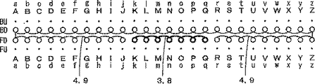
図6は、図5に示すようなインターシャ柄編地3,8を含む筒状の編地を、4枚ベッド横編機で編成する際の針立てを示す。4枚ベッド横編機の基本的な構造やそれを用いた筒状編地の編み方については本願出願人による特公平1−57173号(=米国特許第4905483)等に開示され、既に周知である。前身頃の裾ゴム5は前下部針床(以下、針床FDという。)の針と後上部針床(以下、針床BUという。)の針を使用し、後身頃の裾ゴムは後下部針床(以下、針床BDという。)の針と前上部針床(以下、針床FUという。)の針を使用して編成する。
前身頃の裾ゴム5のコース編成が行われるときは、針床FUの針で編まれる後身頃の裾ゴムの裏目は全て針床BDの針に移されて保持される。これと反対に後身頃の裾ゴム5のコース編成が行われるときは、針床BUの針で編まれる前身頃の裾ゴムの裏目は針床FDの針に移され保持される。つまり前側編地を編成する際に後側編地を針床BDの針に付属させ、反対に後側編地を編成する際に前側編地を針床FDの針に付属させて前側編地と後側編地が前後に重ね合わせた状態で編成する。このようにして筒状の身頃に裾ゴム5を形成する。裾ゴム5に続く身頃は平編み組織で編成するため上記のような編目の移し替えは不要で、前身頃は針床FDの針、後身頃は針床BDの針を使用して編成される。身頃にリンクスや寄せ柄などの組織を身頃に入れる場合は裾ゴム5の編成と同じように裏目を対向する上部針床の針を使用して編目を移し替えながら編成を行うようにする。
インターシャ柄3,8は、グランド編地4,9とは異なるヤーンキャリア(以下、単にキャリアという。)などの給糸部材を使用して編成する。前身頃2,7および後身頃はアルファベットの大文字で示す下部針床の針A,B,C,…を使用してそれぞれ編成する。小文字で示す針a,b,cは上部針床の針を示す。図ではインターシャ柄3,8の編糸を太線で示し、グランド編地4,9の編糸を細線で示す。
針床の上方には、図示しないが複数の糸道レールが懸架され、複数のキャリアが糸道レールに沿って摺動自在であり、針床上を往復走査するキャリッジに設けたカムで連行され、キャリアの給糸口から編糸を針床の任意の針へと供給できるようになっている。各編成コースで、インターシャ柄部分3,8の編成に使用したキャリアは、次のコースでのインターシャ柄編地3,8の編成時に再び使用するために、インターシャ柄編地3,8とグランド編地4,9との境界部付近に停止させておく。すなわち、境界部を挟んで隣接する編地の編成には、異なるキャリアが使用される。このためインターシャ柄編地3,8とグランド編地4,9との境界部付近では、複数のキャリアが錯綜し、キャリアの給糸口同士が互いに干渉したり、休止状態のキャリアに編成動作に供される針の先端が衝突したり、インターシャ柄編地3,8の最終編目から休止状態のキャリアの給糸口に延びる編糸をインターシャ柄編地3,8に隣接するグランド編地4,9の編成時に針の先端で引き込んでしまう糸喰いの問題が発生する恐れがある。
インターシャ柄を編成する際に、キャリアの給糸口を走行方向の前後に揺動変位させることが可能なインターシャ柄編成用のキャリアが考えられている。たとえば、本願出願人は、特公昭61−51061号公報で、キャリアの給糸口を揺動変位させ、休止状態では最終編目からほぼ直上方向に編糸が延びる状態となるようにすることができるキャリアとそれを用いたインターシャ柄の編成方法を開示している。給糸口の位置が変わるキャリアを用いれば、複数のカムシステムを備えるキャリッジで1コースを編成する際に、複数のインターシャ柄を入れることができる。また、特公昭61−23300号公報には、編糸を案内しうる孔を有する下端部を針間の間隙内に突き入らせる上下方向の変位で、キャリア同士間の干渉を避ける先行技術が開示されている。
セータ等のニット衣類を筒状編地として編成しながら、インターシャ柄を入れるインターシャ柄編地の編成方法に関し、本願出願人は特開平10−1852号公報を先に提案している。同公報では、インターシャ柄を前側編地にデザインした筒状編地を編成する方法として、2つの方法を開示している。同公報の図2に示す第1の実施形態では、後側針床での後身頃にはインターシャ柄がなくても、後身頃を編成する際に前身頃のインターシャ柄の境界部のところでその都度それぞれのキャリアを反転移動させるようにして後身頃の編成を分割して行うことでキャリア同士の干渉や、不用意な糸喰いを防ぐようにしている。すなわち、インターシャ柄に対向するグランド部分のコースを編成する際に、a:インターシャ柄用のキャリアをインターシャ柄の範囲内に移動させる蹴り返しを行ってからグランド部分をインターシャ柄の手前まで編成し、b:インターシャ柄用およびグランド部分用のキャリアをインターシャ柄の範囲外に移動させる蹴り返しを行ってから残りのグランド部分を編成している。また、同公報の図3に示す第2の実施形態では、前身頃のインターシャ柄の編成に使用したキャリアを、後身頃の編成時には編地全体の幅よりも外部に退避させておくことによって、干渉や糸喰いを防ぐようにしている。
特開平10−1852号公報で開示している第1の実施形態では、後身頃編成時に折返し編成を行う。同公報の第[0011]段落に記載されているように、折返し編成ではキャリアが反転移動する部分で編目が詰んでしまい、編地の美観を損なう問題がある。この問題に対しては、反転位置にある針で形成される編目の度目を粗げることによって対処しうるけれども、その調整は難しく、手間がかかる。また、後身頃を一気に編成するのではなく、分割して編成しなければならないので、生産性は低くなってしまう。第2の実施形態では、折返しを行う必要はないけれども、同公報の第[0012]段落に記載されているように、編糸を直接上方から給糸部材に供給する必要があり、糸の取り方が限定され、色数を多く取ることができない。
特公昭61−51061号公報で開示しているようなインターシャ編成用のキャリアを用いれば、色数や糸の取り方についての制限は緩和される、また折返し編成が不要になるのでインターシャ境界部での度目調整の必要もない。しかし筒状編地の編成における上記した糸喰いの問題は必ずしも解消されないことが判明している。その理由は給糸口が変位するキャリアであっても、インターシャ柄の境界部で停止する位置の精度は必ずしも充分ではないからである。
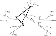
図7は、たとえば針床FDで針Kにインターシャ柄の最後の編目を形成してキャリアの給糸口10が休止している状態を示す。なお図7では理解しやすいように上部針床の針と下部針床の針が見えるように位相をずらして示したが、実際の編機では各針床に装着される上下の針は針床長手方向においてそれぞれ同一位相上に装着されている。針K,L,Mは、編糸11でインターシャ柄の新ループを形成し、旧ループ14がノックオーバされている。キャリアの給糸口10の停止位置がたとえばAの範囲であれば、針床FDの針Kから給糸口10に延びる編糸11を針床BDの針が引込む糸喰いが発生しない。給糸口10と針Kとの間には高低差があるので、Aの範囲は、針床BDの針Jを若干越える位置まで広がる。しかしながら停止精度の関係で、給糸口10を常にAの範囲内に停止させるのは困難である。キャリッジに設けた連行ピンで連行されて走行する形式のキャリアは、転換ピンとの係合が外れると、キャリアは糸道レールの途中で停止する。キャリアと糸道レールとの間には、キャリッジに連行される際には移動しやすいように摺動抵抗が小さく、キャリッジに連行されないときには移動しにくくなるという両立が困難な特性が要求される。摺動抵抗を小さくするためには潤滑油などを塗布し、制動性を高めるためにはマグネットによる吸着力などが利用されるけれども、ヤーンキャリアの停止精度を非常に高くすることは困難である。このため、給糸口10は糸喰いが生じにくい範囲A内に留まることができず、範囲A外などで停止して、糸喰いが生じやすくなってしまうことがある。
本発明の目的は、4枚ベッド横編機を用いてインターシャ柄などの筒状編地を編成する場合でも、不用意な糸喰いの発生を防ぎ、かつ上記したような折り返し編成を不要にして、生産性も良好となるインターシャ柄編地の編成方法を提供することである。
発明の開示
本発明では、前後一対に配設した下部針床と、該下部針床のそれぞれの上位に配設した上部針床を備えた4枚ベッド横編機を使用し、前側編地を編成する際に後側編地を後下部針床の針に付属させ、反対に後側編地を編成する際に前側編地を前下部針床の針に付属させて前後に重ね合わせた状態で両側端で繋がった筒状編地を、針床の長手方向に走行しながら給糸口から編糸を吐出して針に編糸を供給する給糸部材を複数使用して、インターシャ柄を入れて編成するインターシャ柄編地の編成方法において、横編機にはインターシャ編成の前後で、給糸部材から針に編糸を供給する位置を変えるインターシャ編成用の機能を備えておき、インターシャ柄の最終編目を保持する下部針床の針から給糸部材の給糸口に延びる編糸を、該針が属する針床側の上部針床の針でフックして、該編糸を対向する針床の針から遠ざけた状態で、該インターシャ柄が編込まれる編地に対向する編地を編成する。これによれば、インターシャ柄の編成に使用してインターシャ柄の境界部付近で休止するキャリアの給糸口からインターシャ柄の最終編目を保持する針に延びる編糸を、そのインターシャ柄が編込まれる編地に対向する編地を編成する際に、インターシャ柄の最終編目を保持する針が属する針床の上位側の針床の空針にフックさせる。これによりインターシャ柄の最終の編目から給糸口に延びる編糸を対向する針床の針から離れた位置へと退避させられるので、対向する針床の編地を編成する針が編目形成のために進退操作されてもインターシャの編糸を誤って喰わえ込むことを防ぐことができるので従来のようなインターシャ柄の境界付近で分割編成のための折返し編成を行う必要がなくなり、編地の品質を向上させ、製造コストを低減させることができる。
好ましくは前記編糸をフックする上部針床の針は、最終編目を保持する下部針床の針の真上か、近接する針が用いられる。これによれば、編糸の延びる範囲を最終編目を保持する針の付近に留め、糸喰いを充分に防ぐことができる。
好ましくは各針床の針に対して編成動作を行わせるカムを複数組ずつ備えるキャリッジを使用し、前記インターシャ柄が編込まれる編地に対向する編地を編成する際に、前記インターシャ柄の最終編目を保持する針から給糸部材の給糸口に延びる編糸の空針へのフックと、フックされている編糸の解放とを交互に行う。例えば先行側のカムでインターシャ柄の最終編目を保持する下部針床の針から給糸部材の給糸口に延びる編糸を同じ側の上部針床の空針へフックして編糸を退避させてから、続く後行側のカムでインターシャ柄が編込まれる編地に対向する編地を編成する。そしてこのフックした編糸の針からの解放は、先行のカムでインターシャ柄が編込まれる編地に対向する編地を編成した後で後行側のカムでフックした針を進退操作して行うので編地編成の生産性を高めることができる。
発明を実施するための最良の形態
次に本発明の好適な実施例を図面とともに以下説明する。
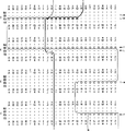
図1および図2は、図5に示したインターシャ柄を有するセーターの筒状編成される身頃を4枚ベッド横編機で編成する場合の編成図を示す。説明の便宜のため身頃の各部分の編成に使用する針数は少なくしている。アルファベットの大文字は下部針床の針、小文字は上部針床の針を示す。裾ゴム5に続く前身頃と後身頃はともに平編み組織で編成され、前身頃は針床FDの針A,B,C,D,…を使用して編成され、後身頃は針床BDの針A,B,C,D,…を使用して編成される。インターシャ柄としては図5(b)に示すような縦縞を例とする。
キャリッジとしては、各針床に対して2組のカムを作用させることができるものを使用する。キャリッジの一方への移動で、先行側のカムをL側、後行側のカムをT側とする。キャリッジが他方へ移動する際には、先行と後行とが入れ替る。キャリアは、例えば特公昭61−51061号公報に開示されるような揺動タイプのものを使用する。本実施形態では、コース1〜6として示す6コースのキャリッジの移動を1サイクルとして、筒状編地の2コース分を編成することができる。なお針床に複合針が装着される。
キャリッジの移動の1コース目では、キャリッジを左端から右の途中まで移動させ、前身頃をL側のカムを使用して針K,L,…P,Qのインターシャ柄部分、T側のカムを使用して針A,B,…I,Jのグランドの左側部分をそれぞれ針床FDで編成する。インターシャ柄部分を編成する編糸の左端は、グランドの左側部分の右端の針Jにタックして繋ぐ。このようにして、インターシャ柄とグランドの左側部分との1コース目が編成される。
キャリッジの移動の2コース目では、キャリッジを右の途中から左端に移動させ、前身頃をL側のカムを使用して針Q,P,…L,Kのインターシャ柄部分、T側のカムを使用して針J,I,…B,Aのグランドの左側部分を編成する。インターシャ柄部分を編成する編糸の右端は、グランドの右側部分の左端の針Rにタックして繋ぐ。グランドの左側部分を編成する編糸の右端は、インターシャ柄部分の左端の針Lにタックして繋ぐ。このようにして、インターシャ柄とグランドの左側部分との2コース目が編成される。
3コース目では、キャリッジを右へ移動させ、L側のカムでキャリアを針Kの右側に移動させるとともにL側のカムでインターシャ柄の左端の針Kからキャリアの給糸口に延びる編糸を針床FUの空針kにフックさせ、T側では針床BDの針A,B,…,Y,Zに給糸して後身頃を編成する。針床FUの空針kは編糸をフックした後は歯口から大きく後退させてキャリアの給糸口へ延びる編糸部分を歯口から遠ざける。この動作はステッチカムの引込み量を大きく設定したり、あるいは上キャリッジに設けた退避カムで強制的に針を引き込むようにする。これにより後身頃の編目を形成する針によってインターシャ柄部分の編成に使用されるキャリアの編糸を不用意に喰えてしまうのをより確実に防ぐことができる。後身頃をT側のカムで編成する際には、針床FDでインターシャ柄の左端となる針Kからの編糸は、針床FUの針kを経由してキャリアの給糸口に延びている。これによって、キャリアの停止位置の精度にばらつきがあっても、不用意に糸喰いが生じにくくすることができる。このようにして、後身頃のグランドの1コース目が編成される。
キャリッジの移動の4コース目では、キャリッジを右端から左の途中に移動させ、T側のカムを使用して針床FDの針Z,Y,…S,Rの前身頃のグランドの右側部分を編成する。キャリッジの移動の5コース目では、キャリッジを左の途中から右端に移動させ、T側のカムを使用して針R,S…Y,Zの前身頃の右側部分を編成する。前身頃のグランドの右側部分を編成する編糸の左端は、インターシャ柄の右端の針Qにタックして繋ぐ。このようにして、前身頃のグランドの右側部分の1コース目と2コース目とが編成される。
キャリッジの移動の6コース目では、キャリッジを右から左端に移動させ、L側のカムを使用して、針Z,Y,…B,Aの後身頃のグランドを編成しながら、T側でキャリアを針kの左側に移動させ、T側のカムで針床FUの針kを進退させてフックされている編糸を針から外す。このようにして、後身頃のグランドの2コース目が編成された後、針床FUの針kにフックされていた編糸が針から払われる。
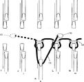
図3および図4は、後身頃を編成するときにインターシャの編糸が針床BDの針に編み込まれないのを説明した図である。なお図3は先の図6と同じように上部針床の針と下部針床の針がわかるように位相をずらして示した。図3に示すように、図1のキャリッジ移動の3コース目では、破線で示すように、針床FDで編成されるインターシャ柄の左端の針Kからキャリアの給糸口10に延びる編糸11を、キャリアの蹴り返しと連動させて、実線で示すように針床FUの空針kにフックさせ、この空針kを大きく後退させる。図4に示すように、針床FUの針kから給糸口10に延びる編糸11は、針床BD側の針が仮想線で示すように歯口に進出してもフックされにくい。破線で示すように針床FDの針Kから給糸口10に編糸が延びていれば、針床BDから歯口に進出する針によって引込まれやすい。この違いによって、本実施形態では糸喰いの発生を防ぐことができる。上記キャリッジのコース1〜6の編成を繰り返し行うことで筒状編地にインターシャ柄編地を形成することできる。
(変形例)
上記の編成では、3コース目でキャリッジを右へ蹴り返して、L側のカムでキャリアを針Kの右側に移動させるとともにインターシャ柄の左端の針Kからキャリアの給糸口に延びる編糸を針床FUの空針kにフックさせ、キャリッジの6コース目の移動でT側のカムでキャリアを針kの左側に蹴り返して、針床FUの針kを進退させてこのフックした編糸を針から外すようにした。しかしこれを以下の編成に代えて本発明を実施することも可能である。
すなわち、キャリッジの移動の2コース目で、キャリッジを右から左に移動させ、前身頃をL側のカムを使用して針床FDの針Q,P,…L,Kのインターシャ柄部分を編成するとともに針床FUの空針jに編糸をフックさせる。この編糸をフックさせる針床FUの針は次のインターシャ柄部分が編成される7コース目においてタック繋ぎされる針床FDの針Jの少なくとも真上かそれよりも外側で針Jに近接した針で行う。そしてT側のカムを使用して針J,I,…B,Aのグランドの左側部分を編成する。なおこのコースでのインターシャ柄部分とグランド部分を繋ぐタックは上記の例と同じく針R、針Lに対して行われる。
続く3〜5コース目は上記の例と同じ編成が行われた後、キャリッジの移動の6コース目では、キャリッジを右から左端に移動させ、L側のカムを使用して、針Z,Y,…B,Aの後身頃のグランドを編成しながら、T側のカムで針床FUの針jを進退させて編糸を針jから外す。そして7コース目を上記の例と同じ編成で行う。この方法では上記例のようにインターシャ柄部分を編成するキャリアを左右に移動して針床FUの空針に編糸をフックさせ、その後払うというキャリアの蹴り返し動作を省略できる。また2コース目に行われる針床FUの針での編糸のフックと、7コース目に行われる針床FDの針でのタック繋ぎが、異なる位相の針で行われる場合には、例えば針iと針J、その場合には6コース目では払いを行わずに7コース目のL側のカムでインターシャ柄部分の編成を行う際に払いとタックを同時に行なうようにすることもできる。
インターシャ柄、たとえばダイヤ柄が横方向に並ぶような場合に、複数のキャリアが接近して休止することがある。このような場合は、キャリア間が少しでも離れるように、フックする空針を選択することが好ましい。
本発明でいう筒状編地とは、上記した前身頃と後身頃が編幅の両端で連結された完全な筒状編地だけでなく、カーディガンなど、一部が分離した状態で編まれる編地も含むもので、このような分離型の筒状編地であっても、本発明を適用して、効率よくインターシャ柄入の編地を編成することができる。
図5(a)に示すダイヤ柄のインターシャ柄編地3などのように、インターシャの柄幅が徐々に増え、徐々に減るような場合でもインターシャ柄を編成することができる。編み幅が急激に変化するインターシャ柄を前身頃に編成する場合は、以上で説明したような方法でまず編み終えた後、この状態で後身頃の編成を行い、次のコースの直前でコースの開始点まで前タックしながら編成すればよい。
なお、図5(b)のインターシャ柄8の帯状領域は、カーディガンのボタン孔を設ける編地として、他の編地よりも強化するために編糸などを替えて編成することもできる。このような編地領域は、他の編地とは別のキャリアを使用して編成するために、境界部でキャリアを休止させておく必要があり、対向する編地を編成する際には、糸喰いを防ぐ必要がある。また、筒状編地の変形としてポケットなどで部分的に編地が対向する場合でも、その部分に関して本発明を適用することができる。このように、本発明の適用対象となるインターシャ柄とは、装飾としての編地領域ばかりではなく、編糸を替えて編成する領域の境界でキャリアを休止させ、対向する編地を編成する必要があるようなものを含むものとする。さらに、筒状編地で後側編地にインターシャ柄があって前側編地を編成する場合や、両側の編地にインターシャ柄がある場合も、本発明を同様に適用することができる。
以上の説明ではインターシャ編成用の機能として、キャリアの給糸口の位置を揺動変位させるスイング式のキャリアを使用した例を示したが、本発明は、上下動や左右動をキャリアの給糸口に与える機能があれば、同様に実施することができる。たとえば、特許第2903152号公報(=米国特許第6047570号)に記載されているような、糸道レールにキャリア蹴り返し用の鋼帯を架設し、モータで左右動させる横編機に、上下動可能なキャリアを組合わせる場合などにも、本発明を適用することができるなど本発明の趣旨を逸脱しない範囲で実施できるのはいうまでもない。
【図面の簡単な説明】
図1は、本発明の実施例として、インターシャ柄を有する筒状編地の編成の前半部分を示す。図2は、図1に続くインターシャ柄を有する筒状編地の編成の後半部分を示す。図3は、図1のキャリッジ移動の3コース目で、編糸を前上部針床の針にフックさせた状態を示す部分的な平面図である。図4は、図2の右側面図である。図5は、インターシャ柄を有する筒状編地の外観を示す。図6は、図4の筒状編地を4枚ベッド横編機で編成する場合の針の使用状態を示す。図7は、キャリアを使用して、糸喰いを生じない範囲を示す部分的な平面図である。TECHNICAL FIELD The present invention relates to a method for knitting an intarsia pattern knitted fabric in which an intarsia pattern is inserted while knitting a knit garment such as a sweater as a non-sewn tubular knitted fabric using a four-bed flat knitting machine.
BACKGROUND ART Conventionally, an intarsia pattern knitted fabric as shown in FIG. 5 is well known as a typical knitted fabric knitted by a flat knitting machine. FIG. 5A shows an example in which an intarsia pattern knitted
FIG. 6 shows a needle stand for knitting a tubular knitted fabric including intarsia pattern knitted
When course knitting of the
The
Although not shown, a plurality of yarn path rails are suspended above the needle bed, a plurality of carriers are slidable along the yarn path rails, and are entrained by a cam provided on a carriage that reciprocally scans the needle bed. The knitting yarn can be supplied to any needle on the needle bed from the yarn feeder of the carrier. In each knitting course, the carrier used for knitting the
An intarsia pattern knitting carrier that can swing and displace the yarn feeder of the carrier back and forth in the traveling direction when knitting the intarsia pattern is considered. For example, in Japanese Patent Publication No. Sho 61-51061, the applicant of the present application can swing and displace the yarn feeder of the carrier so that the knitting yarn extends in a direction almost directly above the final stitch in the rest state. And an intarsia pattern knitting method using the same. If a carrier whose position of the yarn feeder is changed is used, a plurality of intarsia patterns can be inserted when knitting one course with a carriage having a plurality of cam systems. Japanese Patent Publication No. 61-23300 discloses a prior art that avoids interference between carriers by a vertical displacement in which a lower end having a hole capable of guiding a knitting yarn is pushed into a gap between needles. Has been.
The present applicant has previously proposed Japanese Patent Laid-Open No. 10-1852 regarding a knitting method of an intarsia pattern knitted fabric in which an intarsia pattern is knitted while knit clothing such as seta is knitted as a tubular knitted fabric. In this publication, two methods are disclosed as a method of knitting a tubular knitted fabric in which an intarsia pattern is designed on the front knitted fabric. In the first embodiment shown in FIG. 2 of the publication, even when the rear body of the rear needle bed has no intarsia pattern, when the rear body is knitted, at the boundary of the intarsia pattern of the front body Each carrier is reversed and moved so that the knitting of the back body is divided and performed to prevent interference between carriers and inadvertent yarn biting. That is, when knitting the course of the ground portion facing the intarsia pattern, a: kicking back to move the carrier for the intarsia pattern within the range of the intarsia pattern, and then the ground portion in front of the intarsia pattern And b: kicking back to move the carrier for the intarsia pattern and the ground portion out of the range of the intarsia pattern, and then the remaining ground portion is knitted. Further, in the second embodiment shown in FIG. 3 of the publication, the carrier used for knitting the intarsia pattern on the front body is retracted outside the entire width of the knitted fabric when knitting on the back body. , Try to prevent interference and thread eaters.
In the first embodiment disclosed in Japanese Patent Laid-Open No. 10-1852, turn-up knitting is performed at the time of rear body knitting. As described in the paragraph [0011] of the same publication, the folded knitting has a problem that the stitches are clogged at the portion where the carrier is reversed and the aesthetic appearance of the knitted fabric is impaired. This problem can be dealt with by roughening the stitches formed by the needles at the reversal position, but the adjustment is difficult and time-consuming. Further, since the back body is not knitted at once, but must be knitted separately, productivity is lowered. In the second embodiment, although it is not necessary to turn back, as described in the paragraph [0012] of the same publication, it is necessary to supply the knitting yarn directly from above to the yarn supplying member. However, the number of colors cannot be increased.
If the carrier for intarsia knitting as disclosed in Japanese Patent Publication No. 61-51061 is used, restrictions on the number of colors and how to pick up the yarn are alleviated, and folding knitting becomes unnecessary, so the intarsia boundary There is no need to adjust the time in the department. However, it has been found that the above-described problem of yarn biting in the knitting of the tubular knitted fabric is not necessarily solved. The reason is that the accuracy of the position where the yarn feeder is stopped at the boundary portion of the intarsia pattern is not always sufficient even if the carrier is displaced.
FIG. 7 shows a state where the last stitch of the intarsia pattern is formed on the needle K by the needle bed FD and the
The object of the present invention is to prevent the occurrence of inadvertent yarn biting even when a tubular knitted fabric such as an intarsia pattern is knitted using a four-bed flat knitting machine, and eliminates the need for the above described folding knitting. Thus, it is an object of the present invention to provide a knitting method for an intarsia pattern knitted fabric with good productivity.
DISCLOSURE OF THE INVENTION In the present invention, a four-bed flat knitting machine including a lower needle bed arranged in a pair of front and rear and an upper needle bed arranged above each of the lower needle beds is used, and a front knitted fabric is formed. When knitting, the rear knitted fabric is attached to the needles on the lower lower needle bed, and conversely, when the rear knitted fabric is knitted, the front knitted fabric is attached to the needles on the lower lower needle bed and overlapped on the front and back. Using a plurality of yarn feeding members that discharge the knitting yarn from the yarn feeder and feed the knitting yarn to the needle while running in the longitudinal direction of the needle bed through the cylindrical knitted fabric connected at both ends at In the knitting method of the intarsia pattern knitted fabric to be knitted, the flat knitting machine has an intarsia knitting function for changing the position of supplying the knitting yarn from the yarn supplying member to the needle before and after the intarsia knitting. Knitting yarn extending from the needle of the lower needle bed holding the final stitch of the intarsia pattern to the yarn feeder of the yarn feeding member, Hook with the needle of the upper needle bed on the side of the needle bed to which the needle belongs, and knitting the knitted fabric facing the knitted fabric into which the intarsia pattern is knitted while keeping the knitting yarn away from the needle of the opposing needle bed . According to this, a knitting yarn that extends from a yarn feeder of a carrier that is used for knitting an intarsia pattern and rests near the boundary portion of the intarsia pattern to a needle that holds the final stitch of the intarsia pattern, When knitting the knitted fabric opposite to the knitted fabric to be knitted, the needles on the upper side of the needle bed to which the needle holding the final stitch of the intarsia pattern belongs are hooked. As a result, the knitting yarn extending from the final stitch of the intarsia pattern to the yarn feeder is retreated to a position away from the needle on the opposing needle bed, so that the needle for knitting the knitted fabric on the opposing needle bed is used for stitch formation. Therefore, it is possible to prevent accidental biting of the Intarsia knitting yarn even if it is advanced or retracted, so there is no need to perform the reverse knitting for split knitting near the boundary of the Intarsia pattern as in the past. Quality can be improved and manufacturing costs can be reduced.
Preferably, the needle of the upper needle bed for hooking the knitting yarn is a needle just above or close to the needle of the lower needle bed holding the final stitch. According to this, the range in which the knitting yarn extends can be kept near the needle that holds the final stitch, and the yarn biting can be sufficiently prevented.
Preferably, when a knitted fabric facing a knitted fabric into which the intarsia pattern is knitted is knitted using a carriage having a plurality of cams for performing knitting operations on the needles of each needle bed, the intarsia A hook from the needle holding the final stitch of the handle to the empty needle of the knitting yarn extending to the yarn feeder of the yarn supplying member and the releasing of the hooked knitting yarn are alternately performed. For example, the knitting yarn that extends from the needle on the lower needle bed holding the final stitch of the intarsia pattern to the yarn feeder of the yarn feeding member is hooked to the empty needle on the upper needle bed on the same side with the cam on the leading side to retract the knitting yarn Then, a knitted fabric facing the knitted fabric into which the intarsia pattern is knitted is knitted by the subsequent cam on the subsequent side. The hooked knitting yarn is released from the needle by knitting the knitted fabric facing the knitted fabric to which the intarsia pattern is knitted with the preceding cam, and then moving the needle hooked with the trailing cam forward and backward. As a result, the productivity of knitting can be increased.
BEST MODE FOR CARRYING OUT THE INVENTION A preferred embodiment of the present invention will be described below with reference to the drawings.
1 and 2 show knitting diagrams in the case where the body of the sweater having the intarsia pattern shown in FIG. 5 is knitted with a four-bed flat knitting machine. For convenience of explanation, the number of needles used for knitting each part of the body is reduced. The capital letters of the alphabet indicate the needles of the lower needle bed, and the lower case letters indicate the needles of the upper needle bed. The front and back bodies following the
As the carriage, a carriage capable of acting two sets of cams on each needle bed is used. By moving the carriage to one side, the leading cam is set to the L side and the trailing cam is set to the T side. When the carriage moves to the other side, the leading and trailing are switched. As the carrier, for example, a rocking type as disclosed in Japanese Patent Publication No. 61-51061 is used. In the present embodiment, it is possible to knit two courses of the tubular knitted fabric with the movement of the carriage of six courses shown as
In the first course of movement of the carriage, the carriage is moved from the left end to the middle of the right, and the front body is used on the intarsia pattern portion of the needles K, L,... Knitting the left side of the ground of the needles A, B,... I, J with the needle bed FD. The left end of the knitting yarn knitting the intarsia pattern part is tucked and connected to the right end needle J of the left part of the ground. In this way, the first course of the intarsia pattern and the left side portion of the ground is knitted.
In the second course of carriage movement, the carriage is moved from the middle of the right to the left end, the front body is used with the L side cam, the intarsia pattern part of the needles Q, P,... L, K, the T side cam Knitting the left part of the ground of the needles J, I,. The right end of the knitting yarn for knitting the intarsia pattern portion is tucked and connected to the left end needle R of the right side portion of the ground. The right end of the knitting yarn knitting the left side portion of the ground is tucked and connected to the needle L at the left end of the intarsia pattern portion. In this way, the second course of the intarsia pattern and the left side portion of the ground is knitted.
In the third course, the carriage is moved to the right, the carrier is moved to the right side of the needle K with the L side cam, and the knitting yarn extending from the left end needle K of the intarsia pattern to the carrier yarn feeder is moved with the L side cam. The needle body FU is hooked to the empty needle k, and on the T side, yarns are fed to the needles A, B,..., Y, Z of the needle bed BD and the back body is knitted. After hooking the knitting yarn, the empty needle k of the needle bed FU is largely retracted from the mouth and moves away the knitting yarn portion extending to the carrier yarn feeder from the mouth. In this operation, the pull-in amount of the stitch cam is set large, or the needle is forcibly pulled in by a retracting cam provided on the upper carriage. Accordingly, it is possible to more reliably prevent the knitting yarn of the carrier used for knitting the intarsia pattern portion from being inadvertently eaten by the needle forming the stitch of the back body. When the back body is knitted with the cam on the T side, the knitting yarn from the needle K, which is the left end of the intarsia pattern on the needle bed FD, extends to the yarn feeder of the carrier via the needle k of the needle bed FU. Yes. Thereby, even if there is variation in the accuracy of the carrier stop position, it is possible to prevent the occurrence of thread biting carelessly. In this way, the first course of the ground on the back body is formed.
In the fourth course of carriage movement, the carriage is moved halfway from the right end to the left, and the right side of the ground on the front body of the needles Z, Y,. Organize. In the fifth course of carriage movement, the carriage is moved from the middle of the left to the right end, and the right side portion of the front body of the needles R, S... Y, Z is knitted using the T-side cam. The left end of the knitting yarn for knitting the right side portion of the ground of the front body is tucked and connected to the needle Q at the right end of the intarsia pattern. In this way, the first course and the second course of the right part of the ground of the front body are knitted.
In the sixth course of carriage movement, the carriage is moved from the right to the left end, and the carrier on the T side is knitted using the L side cam while knitting the back body ground of the needles Z, Y,. Is moved to the left side of the needle k, and the needle k of the needle bed FU is advanced and retracted by the T-side cam to remove the hooked knitting yarn from the needle. In this way, after the second course of the back body ground is knitted, the knitting yarn hooked to the needle k of the needle bed FU is removed from the needle.
FIG. 3 and FIG. 4 are diagrams illustrating that the knitting yarn of the intarsia is not knitted into the needle of the needle bed BD when the back body is knitted. In FIG. 3, the phase is shifted so that the needles in the upper needle bed and the needles in the lower needle bed can be seen as in FIG. As shown in FIG. 3, in the third course of carriage movement in FIG. 1, as shown by a broken line, the
(Modification)
In the above knitting, the carriage is kicked back to the right in the third course, the carrier is moved to the right side of the needle K with the L side cam, and the knitting yarn extending from the left end needle K of the intarsia pattern to the yarn feeder of the carrier The hook is hooked to the empty needle k of the needle bed FU, the carrier is kicked back to the left side of the needle k by the T-side cam by the movement of the sixth course of the carriage, the needle k of the needle bed FU is advanced and retracted, and this hooked knitting yarn Was removed from the needle. However, it is also possible to implement the present invention instead of the following knitting.
That is, in the second course of the carriage movement, the carriage is moved from right to left, and the intarsia pattern portion of the needles Q, P,... While knitting, the knitting yarn is hooked to the empty needle j of the needle bed FU. The needle of the needle bed FU that hooks the knitting yarn is close to the needle J at least directly above or outside the needle J of the needle bed FD to be tucked in the seventh course where the next intarsia pattern portion is knitted. Do with a needle. Then, the left side portion of the ground of the needles J, I,... B, A is knitted using the T side cam. In this course, the tuck connecting the intarsia pattern portion and the ground portion is performed on the needle R and the needle L as in the above example.
In the subsequent 3rd to 5th courses, the same knitting as in the above example is performed, and in the 6th course of carriage movement, the carriage is moved from the right to the left end, and the needles Z, Y are used by using the L side cam. ,... B, A while knitting the back body ground, the needle j of the needle bed FU is advanced and retracted with the T side cam to remove the knitting yarn from the needle j. Then, the seventh course is performed with the same knitting as the above example. In this method, the carrier kicking back operation of moving the carrier for knitting the intarsia pattern part to the left and right to hook the knitting yarn to the empty needle of the needle bed FU and then paying it can be omitted as in the above example. When the hook of the knitting yarn with the needle of the needle bed FU performed in the second course and the tuck connection with the needle of the needle bed FD performed in the seventh course are performed with needles of different phases, for example, the needle It is also possible to perform the paying and tacking simultaneously when knitting the intarsia pattern portion with the cam on the L side of the 7th course without paying i and the needle J, in this case the 6th course.
When an intarsia pattern, for example, a diamond pattern, is arranged in the horizontal direction, a plurality of carriers may approach and pause. In such a case, it is preferable to select an empty needle to hook so that the carriers are separated as much as possible.
The tubular knitted fabric referred to in the present invention is not only a complete tubular knitted fabric in which the front body and the back body are connected at both ends of the knitting width, but is knitted in a partially separated state such as a cardigan. Including such a knitted fabric, even with such a separate cylindrical knitted fabric, the present invention can be applied to efficiently knit a knitted fabric with an intarsia pattern.
The intarsia pattern can be knitted even when the pattern width of the intarsia gradually increases and decreases like the diamond pattern intarsia pattern knitted
Note that the belt-like region of the
In the above description, an example of using a swing type carrier that swings and displaces the position of the carrier yarn feeder as the function for intarsia knitting has been shown. If there is a function to give to, it can be implemented similarly. For example, as described in Japanese Patent No. 2903152 (= US Pat. No. 6,047,570), a steel belt for carrier kickback is installed on a yarn path rail, and the flat knitting machine is moved up and down by a motor. Needless to say, the present invention can also be applied to combinations of possible carriers without departing from the spirit of the present invention.
[Brief description of the drawings]
FIG. 1 shows the first half of the knitting of a tubular knitted fabric having an intarsia pattern as an embodiment of the present invention. FIG. 2 shows the latter half of the knitting of the tubular knitted fabric having the intarsia pattern following FIG. FIG. 3 is a partial plan view showing a state where the knitting yarn is hooked to the needle of the front upper needle bed in the third course of the carriage movement of FIG. FIG. 4 is a right side view of FIG. FIG. 5 shows the appearance of a tubular knitted fabric having an intarsia pattern. FIG. 6 shows a use state of the needle when the tubular knitted fabric of FIG. 4 is knitted by a four-bed flat knitting machine. FIG. 7 is a partial plan view showing a range in which yarn catching does not occur using a carrier.
Claims (3)
Applications Claiming Priority (3)
| Application Number | Priority Date | Filing Date | Title |
|---|---|---|---|
| JP2001359741 | 2001-11-26 | ||
| JP2001359741 | 2001-11-26 | ||
| PCT/JP2002/012247 WO2003046267A1 (en) | 2001-11-26 | 2002-11-22 | Method of knitting intersia pattern knitted fabric |
Publications (2)
| Publication Number | Publication Date |
|---|---|
| JPWO2003046267A1 JPWO2003046267A1 (en) | 2005-04-07 |
| JP3968081B2 true JP3968081B2 (en) | 2007-08-29 |
Family
ID=19170694
Family Applications (1)
| Application Number | Title | Priority Date | Filing Date |
|---|---|---|---|
| JP2003547691A Expired - Fee Related JP3968081B2 (en) | 2001-11-26 | 2002-11-22 | Intarsia pattern knitting method |
Country Status (8)
| Country | Link |
|---|---|
| US (1) | US6966202B2 (en) |
| EP (1) | EP1462555B1 (en) |
| JP (1) | JP3968081B2 (en) |
| KR (1) | KR100833520B1 (en) |
| CN (1) | CN100443647C (en) |
| AU (1) | AU2002354061A1 (en) |
| DE (1) | DE60228494D1 (en) |
| WO (1) | WO2003046267A1 (en) |
Cited By (1)
| Publication number | Priority date | Publication date | Assignee | Title |
|---|---|---|---|---|
| CN103668734A (en) * | 2012-08-31 | 2014-03-26 | 北京大豪科技股份有限公司 | Method and system for knitting applique |
Families Citing this family (16)
| Publication number | Priority date | Publication date | Assignee | Title |
|---|---|---|---|---|
| JP4002870B2 (en) * | 2003-08-08 | 2007-11-07 | 株式会社島精機製作所 | Method for knitting a tubular knitted fabric having a stripe pattern and a tubular knitted fabric having a stripe pattern |
| JP4163130B2 (en) * | 2004-02-17 | 2008-10-08 | 株式会社島精機製作所 | Intarsia pattern knitting method and knitted fabric, knit design device, and knitting program |
| EP1724385B1 (en) * | 2005-05-21 | 2016-05-18 | H. Stoll AG & Co. KG | Method of making knit fabric on a flat knitting machine |
| DE202006005898U1 (en) * | 2006-04-05 | 2007-08-16 | Strickmanufaktur Zella Gmbh | Piece of upper clothing like a shooting jacket for special sports protection has a body element and long sleeves each with elbow padding with differently designed knitted areas |
| JP5010588B2 (en) * | 2006-05-17 | 2012-08-29 | 株式会社島精機製作所 | Knitting method and flat knitting machine for intarsia pattern knitted fabric |
| JP4891833B2 (en) * | 2007-04-27 | 2012-03-07 | 株式会社島精機製作所 | Method for knitting tubular knitted fabric and tubular knitted fabric |
| JP5757751B2 (en) * | 2011-02-28 | 2015-07-29 | 株式会社島精機製作所 | Knit design equipment |
| DE102011113538B3 (en) * | 2011-09-15 | 2012-08-16 | H. Stoll Gmbh & Co. Kg | Process for the production of a knitted fabric with intarsia pattern and decorative stitches |
| CN102747520A (en) * | 2012-07-24 | 2012-10-24 | 宁波慈星股份有限公司 | Method for weaving by forming eyelets of flat knitting machine |
| CN102776687B (en) * | 2012-07-27 | 2013-10-23 | 宁波慈星股份有限公司 | Method for weaving 5*5 cable with four plain stitches |
| US20160165970A1 (en) * | 2013-07-25 | 2016-06-16 | Drexel University | Knitted electrochemical capacitors and heated fabrics |
| US20150315728A1 (en) * | 2015-07-13 | 2015-11-05 | Sung-Yun Yang | Process of manufacturing fabrics having jacquard and terry patterns |
| EP3612671B1 (en) * | 2017-04-21 | 2022-10-12 | Pilz GmbH & Co. KG | Shape knit fabric and use of a shape knit fabric |
| US11486069B2 (en) * | 2018-09-26 | 2022-11-01 | Santoni S.P.A. | Process for manufacturing a tubular intarsia knitted item by means of a circular weft knitting machine |
| CN114990777A (en) * | 2022-05-24 | 2022-09-02 | 信泰(福建)科技有限公司 | Knitted vamp using invisible applique process |
| CN115287816A (en) * | 2022-09-21 | 2022-11-04 | 福建屹立智能化科技有限公司 | Three-needle bed warp knitting machine and knitted fabric thereof |
Family Cites Families (13)
| Publication number | Priority date | Publication date | Assignee | Title |
|---|---|---|---|---|
| JPS56140139A (en) * | 1980-04-01 | 1981-11-02 | Shima Idea Center | Knitting of intercia pattern and yarn introducing apparatus |
| JPS5771463A (en) * | 1980-10-22 | 1982-05-04 | Kouseishiya Kk | Yarn guide apparatus in traverse type knitting machine |
| DE3424052A1 (en) * | 1984-06-29 | 1986-01-09 | Siemens AG, 1000 Berlin und 8000 München | SIGNALER |
| JPS6468547A (en) * | 1987-09-04 | 1989-03-14 | Shima Seiki Mfg | Traverse knitting machine |
| DE3813504A1 (en) * | 1988-04-22 | 1989-11-02 | Stoll & Co H | METHOD FOR PRODUCING INTARSIA KNITTED PIECES AND FLAT-KNITTING MACHINE FOR IMPLEMENTING THE METHOD |
| US4905453A (en) * | 1988-07-21 | 1990-03-06 | Siebring Barton G | Method and apparatus for manufacturing nested polyethylene bags |
| JP2568135B2 (en) * | 1990-10-12 | 1996-12-25 | 株式会社島精機製作所 | Knitting method for the cut portion of tubular knitted fabric |
| JP3498270B2 (en) * | 1994-04-28 | 2004-02-16 | 株式会社島精機製作所 | Method and apparatus for guiding yarn in flat knitting machine |
| JPH0931804A (en) | 1995-07-17 | 1997-02-04 | Tsudakoma Corp | Knitting of single knit fabric |
| JPH09217254A (en) * | 1996-02-13 | 1997-08-19 | Tsudakoma Corp | Formation of crossing yarn-fixing part |
| JPH101852A (en) * | 1996-06-12 | 1998-01-06 | Shima Seiki Mfg Ltd | Production of cylindrical knitted fabric having intersia portion |
| JP2903152B2 (en) * | 1997-04-15 | 1999-06-07 | 株式会社島精機製作所 | Yarn supply mechanism of flat knitting machine |
| WO2002097178A1 (en) * | 2001-05-25 | 2002-12-05 | Shima Seiki Manufacturing Limited | Method of knitting intersia pattern knitting fabric and knitting program producing device therefor |
-
2002
- 2002-11-22 AU AU2002354061A patent/AU2002354061A1/en not_active Abandoned
- 2002-11-22 CN CNB02823426XA patent/CN100443647C/en not_active Expired - Fee Related
- 2002-11-22 WO PCT/JP2002/012247 patent/WO2003046267A1/en active IP Right Grant
- 2002-11-22 DE DE60228494T patent/DE60228494D1/de not_active Expired - Lifetime
- 2002-11-22 US US10/496,689 patent/US6966202B2/en not_active Expired - Fee Related
- 2002-11-22 EP EP02785946A patent/EP1462555B1/en not_active Expired - Lifetime
- 2002-11-22 JP JP2003547691A patent/JP3968081B2/en not_active Expired - Fee Related
- 2002-11-22 KR KR1020047006915A patent/KR100833520B1/en not_active IP Right Cessation
Cited By (2)
| Publication number | Priority date | Publication date | Assignee | Title |
|---|---|---|---|---|
| CN103668734A (en) * | 2012-08-31 | 2014-03-26 | 北京大豪科技股份有限公司 | Method and system for knitting applique |
| CN103668734B (en) * | 2012-08-31 | 2016-06-01 | 北京大豪科技股份有限公司 | Embossing weaving method and system |
Also Published As
| Publication number | Publication date |
|---|---|
| EP1462555B1 (en) | 2008-08-20 |
| US20050016220A1 (en) | 2005-01-27 |
| EP1462555A1 (en) | 2004-09-29 |
| WO2003046267A1 (en) | 2003-06-05 |
| US6966202B2 (en) | 2005-11-22 |
| EP1462555A4 (en) | 2006-05-24 |
| KR20040066806A (en) | 2004-07-27 |
| CN100443647C (en) | 2008-12-17 |
| KR100833520B1 (en) | 2008-05-29 |
| DE60228494D1 (en) | 2008-10-02 |
| JPWO2003046267A1 (en) | 2005-04-07 |
| AU2002354061A1 (en) | 2003-06-10 |
| CN1592802A (en) | 2005-03-09 |
Similar Documents
| Publication | Publication Date | Title |
|---|---|---|
| JP3968081B2 (en) | Intarsia pattern knitting method | |
| JP3968074B2 (en) | Method of knitting an intarsia pattern knitted fabric and a knitting program generation device therefor | |
| KR100585275B1 (en) | Method of knitting neck portion of knit wear by weft knitting machine and the knit wear | |
| JP2604653B2 (en) | Knitted fabric with pockets having rib knitting and knitting method thereof | |
| WO2006103957A1 (en) | Method of knitting cylindrical fabric in weft knitting machine and weft knitting machine | |
| JP3887406B2 (en) | Knitwear neck knitting method and knitwear | |
| EP2565308B1 (en) | Joining method of neighboring knitted fabric pieces, and knitted fabric | |
| KR101347648B1 (en) | Set-up method of knitted fabric | |
| JP5702576B2 (en) | Knitting method of knitted fabric and knitted fabric | |
| JP3888899B2 (en) | Knitwear knitting method | |
| KR100554200B1 (en) | A stitch loop retaining method by using a flat knitting machine | |
| KR20060013481A (en) | Knitting method for knitting fabric | |
| JP5057711B2 (en) | Sock knitting machine | |
| KR940009399A (en) | Method for manufacturing jacquard pile fabric and sinker for use | |
| KR20210063957A (en) | Knitting method for efficient neck line formation of knitwear | |
| KR19990077454A (en) | A widening method | |
| JPS5860045A (en) | Fabrication of one surface patterned knitted wear product and circular knitting machine therefor | |
| KR101691734B1 (en) | Knitting method for forming hall by continuous process and knitted goods thereby | |
| JPH11315449A (en) | Method for forming increase | |
| JP2023064006A (en) | Flat knitting machine for pile knitting and sinker, and pile knitting method in flat knitting machine | |
| KR100684474B1 (en) | A method for weaving a neck of socks | |
| JP2020016008A (en) | Flat-knitting machine | |
| KR20160137457A (en) | Knitting goods having hall formed by continuous process | |
| JPS59192756A (en) | Method and apparatus for knitting non-curl circular knitted fabric |
Legal Events
| Date | Code | Title | Description |
|---|---|---|---|
| A621 | Written request for application examination |
Free format text: JAPANESE INTERMEDIATE CODE: A621 Effective date: 20050913 |
|
| TRDD | Decision of grant or rejection written | ||
| A01 | Written decision to grant a patent or to grant a registration (utility model) |
Free format text: JAPANESE INTERMEDIATE CODE: A01 Effective date: 20070515 |
|
| A61 | First payment of annual fees (during grant procedure) |
Free format text: JAPANESE INTERMEDIATE CODE: A61 Effective date: 20070601 |
|
| R150 | Certificate of patent or registration of utility model |
Free format text: JAPANESE INTERMEDIATE CODE: R150 |
|
| FPAY | Renewal fee payment (event date is renewal date of database) |
Free format text: PAYMENT UNTIL: 20100608 Year of fee payment: 3 |
|
| FPAY | Renewal fee payment (event date is renewal date of database) |
Free format text: PAYMENT UNTIL: 20110608 Year of fee payment: 4 |
|
| FPAY | Renewal fee payment (event date is renewal date of database) |
Free format text: PAYMENT UNTIL: 20120608 Year of fee payment: 5 |
|
| FPAY | Renewal fee payment (event date is renewal date of database) |
Free format text: PAYMENT UNTIL: 20120608 Year of fee payment: 5 |
|
| FPAY | Renewal fee payment (event date is renewal date of database) |
Free format text: PAYMENT UNTIL: 20130608 Year of fee payment: 6 |
|
| LAPS | Cancellation because of no payment of annual fees |