JP3967889B2 - Card connector device - Google Patents
Card connector device Download PDFInfo
- Publication number
- JP3967889B2 JP3967889B2 JP2001123512A JP2001123512A JP3967889B2 JP 3967889 B2 JP3967889 B2 JP 3967889B2 JP 2001123512 A JP2001123512 A JP 2001123512A JP 2001123512 A JP2001123512 A JP 2001123512A JP 3967889 B2 JP3967889 B2 JP 3967889B2
- Authority
- JP
- Japan
- Prior art keywords
- card
- slide member
- locking
- connector device
- housing
- Prior art date
- Legal status (The legal status is an assumption and is not a legal conclusion. Google has not performed a legal analysis and makes no representation as to the accuracy of the status listed.)
- Expired - Fee Related
Links
Images


Landscapes
- Coupling Device And Connection With Printed Circuit (AREA)
- Details Of Connecting Devices For Male And Female Coupling (AREA)
Description
【0001】
【発明の属する技術分野】
本発明は、カードを抜き差しして使用される機器に装着されるカード用コネクタ装置に関する。
【0002】
【従来の技術】
従来のこの種のカード用コネクタ装置は、例えば、図28に示すように、前端及び上端を開放したカード収容部51を有するハウジング52に金属製のカバー53がカード収容部51の開放上端を塞ぐように取り付けられて4角箱状に形成され、複数本の端子54が前端部をカード収容部51内に位置させてハウジング52の後端部に支持されており、これら端子54の後端部がハウジング52から突出されている。
【0003】
また、カバー53には、その上板を一対の突片を残すように切り欠くことによって孔部55が形成され、この一対の突片がカード収容部51内部に向かって折り曲げられて第1,第2の弾性片56,57を形成している。
【0004】
このカード用コネクタ装置は、回路基板(図示せず)に搭載されて、その回路基板の配線パターンに複数本の端子54の後端部を半田付けして使用され、カード収容部51内にその開放前端から差し込まれたカード(図示省略)の上面を第1,第2の弾性片56,57が押圧して、上記カードの底面に設けられた複数の接点に複数本の端子54の先端部を押し付け、上記カードの接点と上記回路基板の配線パターンとを複数本の端子54により電気的に接続させて、上記カードに対して情報の記録または再生を行うことができるようになっている。
【0005】
【発明が解決しようとする課題】
しかしながら、上述した従来のカード用コネクタ装置にあっては、第1,第2の弾性片56,57の押圧力によって上記カードをカード収容部51内部に保持する構造となっているため、落下等により外部から衝撃力が加わった場合に上記カードがカード収容部51から抜け落ちて上記カードに対する情報の記録再生ができなくなる虞があった。又、ロック状態で抜けない様に押圧力を上げることでも実現可能だが、この場合、カードの挿入・取出し抵抗が過大になりユーザーが扱いにくい物となる。
【0006】
この問題はカード収容部51の相対向する内側壁の一方からカード収容部51内に出退可能に突出する係止部材を設け、この係止部材を上記カードの一側部に形成された凹部に嵌入させて、上記カードをカード収容部51内に係止することで解決できるが、このようにすると、係止部材によって上記カードが係止された状態で上記カードをカード収容部51から誤って抜き出そうとしたときに、上記カードに亀裂や欠け等の破損が生ずる、又はコネクターが破壊されることとなる。
【0007】
本発明はこのような従来技術の事情に鑑みてなされたもので、その目的は、カードをカード収容部内に係止して不用意にカードがカード収容部から抜け落ちるのを防止するとともに、誤操作によってカードがカード収容部から抜き出された場合でもカード又はコネクタの破損を確実に防止することができるカード用コネクタ装置を提供することにある。
【0008】
【課題を解決するための手段】
上記目的を達成するために、本発明のカード用コネクタ装置は、カード収容部を有するハウジングと、このハウジングに支持されて前記カード収容部に差し込まれたカードに押圧されて前進位置から後退位置へ移動するスライド部材と、このスライド部材を後退位置から前進位置へ付勢する復帰ばねと、前記スライド部材を前記復帰ばねの付勢力に抗して後退位置にロックするロック手段とを備え、前記スライド部材には前記カードの側部に形成された凹部に係合する弾性変形可能な係止部材を取り付け、前記ハウジングには前記スライド部材の前後移動に連動して前記係止部材を前記カードの凹部から離脱する方向へ弾性変形させる制御手段を設け、前記スライド部材が後退位置にあるときに前記係止部材は前記カードの凹部に係合して前記カードを抜け止めし、前記スライド部材が前進位置に移動すると前記係止部材は弾性変形して前記カードの凹部から離脱可能で前記カードが抜き取り可能になり、前記スライド部材は前記カードに係合して前記復帰ばねの付勢力による後退位置から前進位置への移動に伴って前記カードを前記カード収容部から排出させる排出手段として機能し、前記スライド部材が後退位置から前進位置に到達したときに、前記制御手段によって前記スライド部材の移動領域に移動した前記係止部材が前記凹部と半分だけ係合して前記カードの飛び出しを抑制することを最も主要な特徴としている。
【0009】
また、上記構成において、前記制御手段は前後方向に対して前進位置側から後退位置側に向かって傾斜した傾斜面で形成され、前記係止部材は板ばね材で前後方向に延びて形成されて、前記凹部に嵌入される係止部と、この係止部に連設されて前記スライド部材に支持される支持部と、前記係止部に設けられ前記傾斜面に摺接する摺接部とを有する構成とした。
【0011】
また、上記構成において、前記ハウジングに形成されたハート型カムと、前記スライド部材に取り付けられ、前記ハート型カムに沿って可動する係合ピンとで、前記ロック手段を構成した。
【0012】
さらに、上記構成において、前記スライド部材の後端部には、前記カード収容部に延出し、前記カードに押圧されて前記スライド部材を前進位置から後退位置へ移動させるとともに、前記復帰ばねの付勢力による前記スライド部材の後退位置から前進位置への移動に伴って前記カードを押圧して前記カード収容部から排出させる延設部が形成され、前記カード収容部の後端面には、前記延設部を受け入れるための許容部が設けられている構成とした。
【0013】
【発明の実施の形態】
以下、本発明のカード用コネクタ装置の一実施形態を図1〜図27に基づいて説明する。
【0014】
このカード用コネクタ装置は、前端及び上端を開放したカード収容部5を有するハウジング1と、カード収容部5の開放上端を塞ぐようにハウジング1に取り付けられた金属製のカバー12と、ハウジング1に支持されてカード収容部5の一側部に沿って前後移動可能とされたスライド部材18と、弾性変形可能に形成されてスライド部材18に取り付けられた係止部材30等で構成されている。
【0015】
このカード用コネクタ装置に用いられるカード41は公知のもので、IC等の電子部品を硬質プラスチック製のケースに収納して形成され、図6及び図7に示すように、先端一隅にテーパ部42が形成され、底面にはその先端部に複数の接点43が一定間隔で並設されている。また、カード41には一側部に凹部44が、また、他側部に凹部45がそれぞれ形成され、凹部45にカード41への情報の書き込みを許可または禁止の状態にするための移動片46が前後方向にスライド自在に装着されている。
【0016】
次に、このカード用コネクタ装置を構成する各部材の具体的構成について順次説明する。
【0017】
ハウジング1は、PBT(ポリブチレンテレフタレート)等の絶縁合成樹脂材で平板状に成形されてなるもので、図1〜図5に示すように、一側部にガイド部2が設けられ、他側部にもう一つのガイド部3が前後方向(矢印X,Y方向)に延びるように形成されて、後端部には起立壁4が立設されている。そして、ガイド部2,3間がカード収容部5とされ、複数本の端子6が前端部をカード収容部5内に位置させ後端部を外側へ突出させて起立壁4にインサート成形又は圧入によって支持されており、起立壁4の内壁面でカード収容部5の後端面が形成され、この後端面に後述する延設部20を受け入れるための許容部7が切欠形成されている。
【0018】
また、ハウジング1には、ガイド部2,3の内側にカード41の底面と当接する凸状の受け部8,9が各々前後方向に延びるように形成され、図8に示すように、ガイド部2の後方に回り込むように膨らんだ一方の受け部8の膨出部分にハート型カム10が設けられ、このハート型カム10は主ガイド溝10aとこの主ガイド溝10aから分岐された往路ガイド溝10b及び復路ガイド溝10cとこれら往路・復路ガイド溝10b,10cによって画成された係止突起10dとで形成されている。
【0019】
さらに、ハウジング1には、ハート型カム10の後方に長孔11が受け部8に沿って前後方向に延びるように穿設され、長孔11にはその内壁面に前後方向に対して後方向(矢印Y方向)に向かうに従いカード収容部5に近づくように傾斜した傾斜面11aが形成されており、この傾斜面11aは係止部材30を弾性変形させる制御手段としての働きをする。
【0020】
カバー12は、ステンレス等の金属平板を折り曲げ加工してなるもので、図1〜図5に示すように、上板13とこの上板13に連設された一対の側板14とで形成されており、一対の側板14の前端下部に突出片14aが一体に形成されている。また、上板13には、その両側部及び中央部がそれぞれ突片を残すように切り欠かれて孔部13a,13b,13cが形成され、これら3つの突片がカード収容部5内部に向かって曲折されて第1,第2,第3の弾性片15,16,17とされている。
【0021】
スライド部材18は、ハウジング1と同様PBT等の絶縁合成樹脂材で成形されてなるもので、図9〜図13に示すように、前後方向(矢印X,Y方向)に延びる直方体状の基部19と、この基部19の後端部に一体に設けられた延設部20とで形成されている。基部19には、前後方向に延びる支持溝21とこの支持溝21の後端部に連続する貫通孔22とが設けられており、延設部20には、その下面にガイド突起23が突設されている。また、基部19の上面に後方向(矢印Y方向)に向かうに従い先細るV字溝24が形成され、このV字溝24の後端部に小孔25が穿設されおり、基部19の下面には後端が開放されたばね収納部26が前後方向に延びるように形成され、保持突起26aがばね収納部26の前端内壁面に設けられているとともに、ばね収納部26と貫通孔22との間にもう一つのガイド突起27が形成されている。
【0022】
そして、図14に示すように、このスライド部材18は、基部19と一方のガイド突起23との間に受け部8を嵌め込んで、他方のガイド突起27を長孔11の傾斜面11aと対向する内壁面に摺接させることによって、延設部20をカード収容部5に延出させた状態で、これら内壁面と受け部8とに案内されてカード収容部5の一側部に沿って前後移動可能にハウジング1に支持されており、図20に示すように、スライド部材18には、金属線材の前後両端を下方に曲折形成してなる係合ピン28が後端部28aを小孔25に嵌挿させて回動自在に取り付けられ、係合ピン28が前端部28bをハート型カム10内に挿入させてスライド部材18の前後移動に伴いハート型カム10に沿って可動するようになっている。
【0023】
また、ばね収容部26には円筒状の復帰ばね29が前端部を保持突起26aに嵌挿させて収納保持され、この復帰ばね29の後端部が起立壁4の内壁面を弾発することによってスライド部材18を前方向(矢印X方向)へ付勢し、これによりスライド部材18が図20に示す前進位置にあるときに、係合ピン28の前端部28bがハート型カム10の主ガイド溝10aの前端部に位置し、図8に示す領域Aに配置された状態となっている。
【0024】
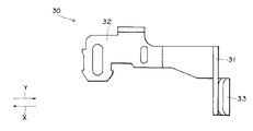
係止部材30は、前後方向に延びる金属製の板ばね材からなるもので、図15及び図16に示すように、その後端部を曲折して形成された係止部31と、この係止部31に連設された支持部32と、係止部31の下縁に延設された摺接部33とで形成されている。そして、図17〜図19に示すように、この係止部材30は、支持部32を支持溝21に強嵌合で挿入させて、係止部31と摺接部33とをそれぞれ貫通孔22から突出させた状態でスライド部材18に取り付けられており、図20に示すように、摺接部33と傾斜面11aとの摺接によって係止部材30が係止部31と支持部32との連結部分を支点として弾性変形することにより、スライド部材30が前進位置にあるときに、係止部31が貫通孔22内に引き込まれてスライド部材18の移動領域に退避した状態となっている。
【0025】
本実施形態に係るカード用コネクタ装置は上記したように構成されており、次に、その動作について説明する。
【0026】
このカード用コネクタ装置は、回路基板(図示せず)に搭載されて、その回路基板の配線パターンに複数本の端子6の後端部を半田付けして使用され、カード41をカード収容部5内にその開放前端より差し込むと、カード41がガイド部2,3に案内されてカード収容部5内に導入され、図21に示すように、テーパ部42とカード41の一側部とに押圧されて係止部材30が係止部31と支持部32との連結部分を支点として弾性変形することによって係止部31が貫通孔22内に逃がされる。
【0027】
カード41をカード収容部5内にさらに差し込むと、カード41によって第1,第2の弾性片15,16が自身の弾性に抗して上方に押し上げられて、図25に示すように、第1,第2の弾性片15,16がカード41の上面に乗り上がり、カード41の先端部及びテーパ部42がスライド部材18の延設部20に突き当たる。このとき、図22に示すように、凹部44が係止部31に到達してカード41の一側部による押圧が解除され、係止部材30の弾性復帰力によって係止部31が凹部44に半分だけ係合する。
【0028】
この状態でさらにカード41をカード収容部5内に差し込むと、カード41の先端部に延設部20が押圧されてスライド部材18が前進位置から後方向(矢印Y方向)へ移動する。この際、係合ピン28の前端部28bが図8に示す主ガイド溝10aの領域Aから領域B及び往路ガイド溝10bの領域C,Dをこの順に経て領域Eに至り、図23に示すように、係合ピン28の前端部28bが係止突起10dに係止されることによって、スライド部材18が復帰ばね29の前方向(矢印X方向)への付勢力に抗して後退位置にロックされる。
【0029】
また、スライド部材18が前進位置から後方向へ移動する過程で、摺接部33と傾斜面11aとの摺接によって係止部材30の弾性変形が除々に解除され、図23に示すように、スライド部材18が後退位置にロックされたときには、係止部材30が自身の弾性によって元の状態に復元し、係止部31が凹部44に嵌入してカード41をカード収容部5に係止する。
【0030】
また、スライド部材18が前進位置から後退位置へ移動するこの過程で、カード41によって第3の弾性片17が自身の弾性に抗して上方に押し上げられて、図26に示すように、第3の弾性片17がカード41の上面に乗り上がり、スライド部材18が後退位置にロックされたときには、第3の弾性片17がカード41の上面の接点43に対応する部分を押圧し、第1,第2の弾性片15,16と協力して接点43を複数本の端子6に押し付けることにより、カード41の接点43が複数本の端子6とそれぞれ接続される。
【0031】
このようにして複数本の端子6によってカード41の接点43と上記回路基板の配線パターンとが接続された後、このカード用コネクタ装置は、カード41と上記回路基板との間で記録再生信号の授受が行われ、カード41に対して情報の記録または再生を行うことができるようになっている。
【0032】
尚、この状態で誤ってカード41を抜き出そうとした場合には、図24に示すように、係止部材30が係止部31と支持部32との連結部分を支点として弾性変形することによって、係止部31が凹部44から離脱して貫通孔22内に逃げスライド部材18の移動領域に退避するため、係止部材30の係止を速やかに解除することができ、この係止によるカード41及びコネクタの破損が確実に防止される。
【0033】
次に、カード41をカード収容部5から排出する場合は、カード41をカード収容部5内にさらに差し込むと、カード41に延設部20が押圧され、図27に示すように、延設部20が許容部7内に進入してスライド部材18が後方向へ若干移動することによって、係合ピン28の前端部28bが図8に示す復路ガイド溝11cの領域Fへ移動し、係合ピン28と係止突起10dとの係止が外れてスライド部材18のロックが解除され、スライド部材18が復帰ばね28の付勢力で前方向(矢印X方向)へ移動する。この際、スライド部材18は排出手段として機能し、その延設部20が復帰ばね29の付勢力でカード41の先端部を押圧して、カード41をカード収容部5から排出させる。
【0034】
また、このとき、図8に示すように、係合ピン28の前端部28bは復路ガイド溝11cの領域Fから領域G及び領域Bをこの順に通って移動し、スライド部材18が前進位置に到達したときには元の領域Aに位置する。
【0035】
また、スライド部材18の後退位置から前進位置への移動に連動して、摺接部33と傾斜面11aとの摺接によって係止部材30が除々に弾性変形し、スライド部材18が前進位置に到達したときには、図22に示したように、係止部31が貫通孔22内に引き込まれてスライド部材18の移動領域に退避し係止部31が凹部44に半分だけ係合した状態となる。この係合により復帰ばね29の付勢力によるカード41の飛び出しが抑えられ、カード収容部5からのカード41の飛び出し量を常に一定とすることができるため、飛び出し量のばらつきに起因するカード41の損傷やこれに収納された前記電子部品の損傷を防止することができる。
【0036】
そして、この状態でカード41を引き抜くと、係止部材30が半分だけ弾性変形することによって係止部31と凹部44との係合が解除され、図21に示したように、係止部31が貫通孔22内に逃がされてカード収容部5からカード41を容易に抜き出すことができる。
【0037】
尚、この実施形態では、係止部材30による係止と第1,第2,第3の弾性片15,16,17の押圧力とによって、カード41をカード収容部5に確実に保持する構造で説明したが、本発明はこれに限定されるものではなく、カード41の上面を押圧する弾性片の個数やその配設位置については種々の変更が可能である。
【0038】
また、この実施形態で示したカード用コネクタ装置にあっては、係止部材30が図21に示した如く弾性変形することから、凹部44の形成されていないカードでも抜き差し可能であるため、凹部44のあるカード41と凹部44のないカードとの2種類のカードに対して支障なく情報の記録または再生を行うことができる。
【0039】
【発明の効果】
本発明は、以上説明したような形態で実施され、以下に記載されるような効果を奏する。
【0040】
本発明のカード用コネクタ装置は、前端を開放したカード収容部を有するハウジングにスライド部材を前記カード収容部の一側部に沿って前後移動自在に支持し、このスライド部材にカードを係止する係止部材を取り付け、前記ハウジングには前記スライド部材の前後移動に連動して前記係止部材を弾性変形させる制御手段を設け、前記カードを前記カード収容部から誤って抜き出した際に、前記係止部材が弾性変形することによって前記凹部から離脱して前記スライド部材の移動領域に退避するようにしたので、外部からの衝撃力による前記カードの抜け落ちを防止できるとともに、誤って抜き出した際の前記カード及びコネクタの破損を確実に防止することができる。又、ロック時の抜けにくさ(耐衝撃)と排出時の挿入・取り出し易さを両立できる。
【0041】
また、前記制御手段を傾斜面で形成し、前記係止部材を板ばね材で形成したので、これら制御手段及び係止部材の構造を簡素化することができ、前記機能を(品質を)を満たし、より安価なコネクタ装置を提供することができる。
【0042】
また、前記スライド部材が前進位置に到達したときに、前記係止部材に備わる係止部が前記凹部と係合して前記カードの飛び出しを抑制するようにしたので、前記カードの排出時の飛び出し量を常時一定にすることができるため、飛び出し量の不安定さに起因する前記カードの損傷が防止でき、コネクタ装置の信頼性を向上させることができる。
【0043】
また、ハート型カムとこのハート型カムに沿って可動する係合ピンとで、前記係止部材によって前記カードが係止されたときに、前記スライド部材をロックするロック手段を構成したので、前記スライド部材を簡単な構成で確実にロックすることができる。
【0044】
さらに、前記スライド部材には、前記カードに押圧されて前記カード収容部の一側部に沿って前記スライド部材を移動させる延設部を設け、前記カード収容部の後端面には、前記延設部を受け入れるための許容部を形成したので、前記延設部と前記カード収容部の後端面との衝突を防止しつつ、前記スライド部材の移動方向におけるコネクタ装置の外形寸法を短縮することができるため、コネクタ装置の品質の安定化と小型化とを促進することができる。
【図面の簡単な説明】
【図1】本発明のカード用コネクタ装置の斜視図である。
【図2】該カード用コネクタ装置の底面側から見た斜視図である。
【図3】該カード用コネクタ装置の平面図である。
【図4】該カード用コネクタ装置の右側面図である。
【図5】該カード用コネクタ装置の底面図である。
【図6】該カード用コネクタ装置に用いられるカードの平面図である。
【図7】その底面図である。
【図8】該カード用コネクタ装置に備えられるハウジングの要部拡大平面図である。
【図9】該カード用コネクタ装置に備えられるスライド部材の平面図である。
【図10】該スライド部材の正面図である。
【図11】該スライド部材の左側面図である。
【図12】該スライド部材の底面図である。
【図13】該スライド部材の背面図である。
【図14】該スライド部材がハウジングに支持された状態を示す平面図である。
【図15】該カード用コネクタ装置に備えられる係止部材の平面図である。
【図16】該係止部材の右側面図である。
【図17】該係止部材がスライド部材に取り付けられた状態を示す平面図である。
【図18】その左側面図である。
【図19】その底面図である。
【図20】本発明のカード用コネクタ装置のカード未装着状態を示す説明図であって、Aは上面側から見た状態を示し、Bは底面側から見た状態を示す。
【図21】本発明のカード用コネクタ装置にカードが差し込まれる過程を示す説明図であって、Aは上面側から見た状態を示し、Bは底面側から見た状態を示す。
【図22】本発明のカード用コネクタ装置に差し込まれたカードの凹部に係止部材が係合した状態を示す説明図であって、Aは上面側から見た状態を示し、Bは底面側から見た状態を示す。
【図23】本発明のカード用コネクタ装置に差し込まれたカードの凹部に係止部材が嵌入した状態を示す説明図であって、Aは上面側から見た状態を示し、Bは底面側から見た状態を示す。
【図24】本発明のカード用コネクタ装置に差し込まれたカードが誤って引き抜かれる状態を示す説明図であって、Aは上面側から見た状態を示し、Bは底面側から見た状態を示す。
【図25】本発明のカード用コネクタ装置の図22の状態における平面図である。
【図26】本発明のカード用コネクタ装置の図23の状態における平面図である。
【図27】本発明のカード用コネクタ装置の図26の状態から更にカードを差し込んだ平面図である。
【図28】従来のカード用コネクタ装置の平面図である。
【符号の説明】
1 ハウジング
2,3 ガイド部
4 起立壁
5 カード収容部
6 端子
7 許容部
8,9 受け部
10 ハート型カム
10a 主ガイド溝
10b 往路ガイド溝
10c 復路ガイド溝
10d 係止突起
11 長孔
11a 傾斜面
12 カバー
13 上板
13a,13b,13c 孔部
14 側板
14a 突出片
15 第1の弾性片
16 第2の弾性片
17 第3の弾性片
18 スライド部材
19 基部
20 延設部
21 支持溝
22 貫通孔
23 ガイド突起
24 V字溝
25 小孔
26 ばね収容部
26a 保持突起
27 ガイド突起
28 係合ピン
28a 後端部
28b 前端部
29 復帰ばね
30 係止部材
31 係止部
32 支持部
33 摺接部
41 カード
42 テーパ部
43 接点
44,45 凹部[0001]
BACKGROUND OF THE INVENTION
The present invention relates to a card connector device to be attached to a device used by inserting and removing a card.
[0002]
[Prior art]
In the conventional card connector device of this type, for example, as shown in FIG. 28, a
[0003]
Further, the
[0004]
This card connector device is mounted on a circuit board (not shown), and is used by soldering the rear ends of a plurality of
[0005]
[Problems to be solved by the invention]
However, the conventional card connector device described above has a structure in which the card is held inside the
[0006]
The problem is that a locking member that protrudes from one of the opposing inner side walls of the
[0007]
The present invention has been made in view of such circumstances of the prior art, and its purpose is to prevent the card from being inadvertently dropped out of the card accommodating portion by locking the card in the card accommodating portion, and by mistaken operation. An object of the present invention is to provide a card connector device that can reliably prevent damage to a card or a connector even when the card is pulled out from a card housing portion.
[0008]
[Means for Solving the Problems]
In order to achieve the above object, a card connector device according to the present invention comprises a housing having a card housing portion and a card supported by the housing and inserted into the card housing portion to be pushed from a forward position to a backward position. A slide member that moves; a return spring that urges the slide member from a retracted position to a forward position; and a lock means that locks the slide member in a retracted position against the urging force of the return spring, An elastically deformable locking member that engages with a recess formed in a side portion of the card is attached to the member, and the locking member is mounted on the housing in conjunction with the back-and-forth movement of the slide member. A control means for elastically deforming in a direction in which the slide member is disengaged, and when the slide member is in the retracted position, the locking member engages with the recess of the card and And retaining the card, the slide member is the locking member to be moved to the advanced position Ri can possible to name extraction the card disengaged from the recess of the card is elastically deformed, the slide member is engaged to the card When the slide member reaches the advance position from the retreat position, it functions as a discharge means for ejecting the card from the card accommodating portion with the movement from the retreat position to the advance position by the biasing force of the return spring. The most important feature is that the locking member, which has been moved to the moving region of the slide member by the control means, engages only half of the recess and prevents the card from popping out .
[0009]
Further, in the above configuration, the control means is formed by an inclined surface inclined from the forward position side toward the backward position side with respect to the front-rear direction, and the locking member is formed by a leaf spring material extending in the front-rear direction. A locking portion that is fitted into the recess, a support portion that is connected to the locking portion and is supported by the slide member, and a sliding contact portion that is provided on the locking portion and that slides on the inclined surface. It was set as the structure which has.
[0011]
In the above configuration, the locking means is configured by a heart-shaped cam formed on the housing and an engagement pin attached to the slide member and movable along the heart-shaped cam.
[0012]
Further, in the above configuration, the slide member has a rear end portion that extends to the card housing portion and is pressed by the card to move the slide member from the forward movement position to the backward movement position, and the biasing force of the return spring As the slide member moves from the retracted position to the advanced position, an extending portion is formed that presses the card and ejects the card from the card accommodating portion, and the extending portion is formed on the rear end surface of the card accommodating portion. It was set as the structure by which the allowance part for accepting was provided.
[0013]
DETAILED DESCRIPTION OF THE INVENTION
Hereinafter, an embodiment of a card connector device of the present invention will be described with reference to FIGS.
[0014]
The card connector device includes a
[0015]
A
[0016]
Next, a specific configuration of each member constituting the card connector device will be sequentially described.
[0017]
The
[0018]
Further, the
[0019]
Further, a long hole 11 is formed in the
[0020]
The
[0021]
The
[0022]
As shown in FIG. 14, the
[0023]
In addition, a
[0024]
The locking
[0025]
The card connector device according to the present embodiment is configured as described above. Next, the operation thereof will be described.
[0026]
This card connector device is mounted on a circuit board (not shown) and used by soldering the rear ends of a plurality of
[0027]
When the
[0028]
When the
[0029]
Further, in the process in which the
[0030]
In this process of moving the
[0031]
After the
[0032]
If the
[0033]
Next, when the
[0034]
At this time, as shown in FIG. 8, the
[0035]
In conjunction with the movement of the
[0036]
When the
[0037]
In this embodiment, the
[0038]
Further, in the card connector device shown in this embodiment, since the locking
[0039]
【The invention's effect】
The present invention is implemented in the form as described above, and has the following effects.
[0040]
In the card connector device of the present invention, a slide member is supported on a housing having a card housing part with an open front end so as to be movable back and forth along one side of the card housing part, and the card is locked to the slide member. A locking member is attached, and the housing is provided with control means for elastically deforming the locking member in conjunction with the back-and-forth movement of the slide member, and when the card is accidentally pulled out from the card housing portion, the engagement member is provided. Since the stopper member is elastically deformed so as to be detached from the recess and retracted to the moving region of the slide member, it is possible to prevent the card from falling off due to an impact force from the outside, and when the card is accidentally extracted The card and the connector can be reliably prevented from being damaged. Moreover, it is possible to achieve both the difficulty of falling out when locking (shock resistance) and the ease of insertion and removal when discharging.
[0041]
Further, the control means is formed by inclined surfaces, since the locking member is formed of a plate spring material, the structure of these control means and the locking member can be simplified, the function (quality) It is possible to provide a connector device that satisfies and is less expensive.
[0042]
Further, when the slide member reaches the forward movement position, the locking portion provided on the locking member engages with the concave portion to suppress the card from popping out. Since the amount can always be constant, the card can be prevented from being damaged due to instability of the pop-out amount, and the reliability of the connector device can be improved.
[0043]
Further, since the heart-shaped cam and the engagement pin movable along the heart-shaped cam constitute a locking means for locking the slide member when the card is locked by the locking member, the slide The member can be reliably locked with a simple configuration.
[0044]
Further, the slide member is provided with an extending portion that is pressed by the card and moves the slide member along one side portion of the card accommodating portion, and the extending portion is provided on a rear end surface of the card accommodating portion. Since the allowance portion for receiving the portion is formed, the outer dimension of the connector device in the moving direction of the slide member can be shortened while preventing the extension portion and the rear end surface of the card housing portion from colliding with each other. Therefore, it is possible to promote stabilization of the quality and miniaturization of the connector device.
[Brief description of the drawings]
FIG. 1 is a perspective view of a card connector device of the present invention.
FIG. 2 is a perspective view of the card connector device as viewed from the bottom side.
FIG. 3 is a plan view of the card connector device.
FIG. 4 is a right side view of the card connector device.
FIG. 5 is a bottom view of the card connector device.
FIG. 6 is a plan view of a card used in the card connector device.
FIG. 7 is a bottom view thereof.
FIG. 8 is an enlarged plan view of a main part of a housing provided in the card connector device.
FIG. 9 is a plan view of a slide member provided in the card connector device.
FIG. 10 is a front view of the slide member.
FIG. 11 is a left side view of the slide member.
FIG. 12 is a bottom view of the slide member.
FIG. 13 is a rear view of the slide member.
FIG. 14 is a plan view showing a state in which the slide member is supported by a housing.
FIG. 15 is a plan view of a locking member provided in the card connector device.
FIG. 16 is a right side view of the locking member.
FIG. 17 is a plan view showing a state in which the locking member is attached to the slide member.
FIG. 18 is a left side view thereof.
FIG. 19 is a bottom view thereof.
FIGS. 20A and 20B are explanatory views showing a card unmounted state of the card connector device of the present invention, wherein A shows a state viewed from the top surface side, and B shows a state viewed from the bottom surface side.
FIGS. 21A and 21B are explanatory views showing a process of inserting a card into the card connector device of the present invention, wherein A shows a state seen from the upper surface side, and B shows a state seen from the bottom surface side.
FIG. 22 is an explanatory view showing a state in which a locking member is engaged with a concave portion of a card inserted into the card connector device of the present invention, wherein A shows a state viewed from the top surface side, and B shows a bottom surface side. The state seen from.
FIGS. 23A and 23B are explanatory views showing a state in which the locking member is inserted into the concave portion of the card inserted into the card connector device of the present invention, where A shows the state viewed from the top surface side, and B shows the bottom surface side. Shows the state of viewing.
FIGS. 24A and 24B are explanatory views showing a state in which a card inserted into the card connector device of the present invention is pulled out by mistake, wherein A shows a state seen from the top surface side, and B shows a state seen from the bottom surface side. FIGS. Show.
25 is a plan view of the card connector device according to the present invention in the state shown in FIG. 22;
26 is a plan view of the card connector device of the present invention in the state shown in FIG. 23. FIG.
27 is a plan view in which a card is further inserted from the state shown in FIG. 26 of the card connector device of the present invention.
FIG. 28 is a plan view of a conventional card connector device.
[Explanation of symbols]
DESCRIPTION OF
Claims (4)
Priority Applications (1)
| Application Number | Priority Date | Filing Date | Title |
|---|---|---|---|
| JP2001123512A JP3967889B2 (en) | 2001-04-20 | 2001-04-20 | Card connector device |
Applications Claiming Priority (1)
| Application Number | Priority Date | Filing Date | Title |
|---|---|---|---|
| JP2001123512A JP3967889B2 (en) | 2001-04-20 | 2001-04-20 | Card connector device |
Publications (2)
| Publication Number | Publication Date |
|---|---|
| JP2002319453A JP2002319453A (en) | 2002-10-31 |
| JP3967889B2 true JP3967889B2 (en) | 2007-08-29 |
Family
ID=18973055
Family Applications (1)
| Application Number | Title | Priority Date | Filing Date |
|---|---|---|---|
| JP2001123512A Expired - Fee Related JP3967889B2 (en) | 2001-04-20 | 2001-04-20 | Card connector device |
Country Status (1)
| Country | Link |
|---|---|
| JP (1) | JP3967889B2 (en) |
Families Citing this family (2)
| Publication number | Priority date | Publication date | Assignee | Title |
|---|---|---|---|---|
| JP2008053124A (en) | 2006-08-25 | 2008-03-06 | Jst Mfg Co Ltd | Card connector |
| JP5883366B2 (en) | 2012-09-06 | 2016-03-15 | ヒロセ電機株式会社 | Electrical connector assembly |
-
2001
- 2001-04-20 JP JP2001123512A patent/JP3967889B2/en not_active Expired - Fee Related
Also Published As
| Publication number | Publication date |
|---|---|
| JP2002319453A (en) | 2002-10-31 |
Similar Documents
| Publication | Publication Date | Title |
|---|---|---|
| JP4006408B2 (en) | Composite connector for card | |
| US6814596B2 (en) | Card connector having low profile and vision indicator | |
| US6976879B2 (en) | Card connector | |
| KR101110383B1 (en) | Card Connector | |
| US9236692B2 (en) | Card connector | |
| US7238034B2 (en) | Memory card connector | |
| US7374440B2 (en) | Card connector with metal shell | |
| KR20100026909A (en) | Memory card connector | |
| KR100999873B1 (en) | Memory card connector | |
| US7267565B2 (en) | Card connector with ejector | |
| JP2007227215A (en) | Connector for card | |
| JP4576354B2 (en) | Card connector | |
| JP4226869B2 (en) | Card connector | |
| JP3967889B2 (en) | Card connector device | |
| WO2004032289A1 (en) | Memory card connector | |
| US20070149017A1 (en) | Card connector with an ejector | |
| JP3772788B2 (en) | Card connector | |
| US7371087B2 (en) | Card connector with a frame | |
| JP3948938B2 (en) | Card connector device | |
| JP3827584B2 (en) | Card connector device | |
| JP3789727B2 (en) | Card connector device | |
| JP2006114437A (en) | Card connector | |
| JP4835748B2 (en) | Memory card connector | |
| JP3945432B2 (en) | Memory card socket | |
| JP2006294637A (en) | Connector for card |
Legal Events
| Date | Code | Title | Description |
|---|---|---|---|
| A621 | Written request for application examination |
Free format text: JAPANESE INTERMEDIATE CODE: A621 Effective date: 20040525 |
|
| A977 | Report on retrieval |
Free format text: JAPANESE INTERMEDIATE CODE: A971007 Effective date: 20060526 |
|
| A131 | Notification of reasons for refusal |
Free format text: JAPANESE INTERMEDIATE CODE: A131 Effective date: 20060606 |
|
| A521 | Written amendment |
Free format text: JAPANESE INTERMEDIATE CODE: A523 Effective date: 20060724 |
|
| A131 | Notification of reasons for refusal |
Free format text: JAPANESE INTERMEDIATE CODE: A131 Effective date: 20070116 |
|
| A521 | Written amendment |
Free format text: JAPANESE INTERMEDIATE CODE: A523 Effective date: 20070123 |
|
| TRDD | Decision of grant or rejection written | ||
| A01 | Written decision to grant a patent or to grant a registration (utility model) |
Free format text: JAPANESE INTERMEDIATE CODE: A01 Effective date: 20070522 |
|
| A61 | First payment of annual fees (during grant procedure) |
Free format text: JAPANESE INTERMEDIATE CODE: A61 Effective date: 20070601 |
|
| FPAY | Renewal fee payment (event date is renewal date of database) |
Free format text: PAYMENT UNTIL: 20100608 Year of fee payment: 3 |
|
| FPAY | Renewal fee payment (event date is renewal date of database) |
Free format text: PAYMENT UNTIL: 20100608 Year of fee payment: 3 |
|
| FPAY | Renewal fee payment (event date is renewal date of database) |
Free format text: PAYMENT UNTIL: 20110608 Year of fee payment: 4 |
|
| LAPS | Cancellation because of no payment of annual fees |