JP3967518B2 - Offset measurement method, tool position detection method, and bonding apparatus - Google Patents
Offset measurement method, tool position detection method, and bonding apparatus Download PDFInfo
- Publication number
- JP3967518B2 JP3967518B2 JP2000059843A JP2000059843A JP3967518B2 JP 3967518 B2 JP3967518 B2 JP 3967518B2 JP 2000059843 A JP2000059843 A JP 2000059843A JP 2000059843 A JP2000059843 A JP 2000059843A JP 3967518 B2 JP3967518 B2 JP 3967518B2
- Authority
- JP
- Japan
- Prior art keywords
- tool
- position detection
- plane
- reference member
- pickup device
- Prior art date
- Legal status (The legal status is an assumption and is not a legal conclusion. Google has not performed a legal analysis and makes no representation as to the accuracy of the status listed.)
- Expired - Fee Related
Links
- 238000001514 detection method Methods 0.000 title claims description 113
- 238000000691 measurement method Methods 0.000 title claims description 4
- 238000005259 measurement Methods 0.000 claims description 29
- 230000003287 optical effect Effects 0.000 claims description 27
- 238000003384 imaging method Methods 0.000 claims description 18
- 238000000034 method Methods 0.000 claims description 14
- 238000012545 processing Methods 0.000 description 19
- 238000012937 correction Methods 0.000 description 17
- 238000010586 diagram Methods 0.000 description 4
- 238000007373 indentation Methods 0.000 description 3
- 238000012986 modification Methods 0.000 description 3
- 230000004048 modification Effects 0.000 description 3
- 239000004065 semiconductor Substances 0.000 description 3
- 238000006243 chemical reaction Methods 0.000 description 2
- 238000005286 illumination Methods 0.000 description 2
- 239000013307 optical fiber Substances 0.000 description 2
- 230000000007 visual effect Effects 0.000 description 2
- 241000283070 Equus zebra Species 0.000 description 1
- 238000013459 approach Methods 0.000 description 1
- 229910052736 halogen Inorganic materials 0.000 description 1
- 150000002367 halogens Chemical class 0.000 description 1
- 239000012925 reference material Substances 0.000 description 1
- WFKWXMTUELFFGS-UHFFFAOYSA-N tungsten Chemical compound [W] WFKWXMTUELFFGS-UHFFFAOYSA-N 0.000 description 1
- 229910052721 tungsten Inorganic materials 0.000 description 1
- 239000010937 tungsten Substances 0.000 description 1
Images


Classifications
-
- H—ELECTRICITY
- H01—ELECTRIC ELEMENTS
- H01L—SEMICONDUCTOR DEVICES NOT COVERED BY CLASS H10
- H01L24/00—Arrangements for connecting or disconnecting semiconductor or solid-state bodies; Methods or apparatus related thereto
- H01L24/74—Apparatus for manufacturing arrangements for connecting or disconnecting semiconductor or solid-state bodies
- H01L24/78—Apparatus for connecting with wire connectors
-
- B—PERFORMING OPERATIONS; TRANSPORTING
- B23—MACHINE TOOLS; METAL-WORKING NOT OTHERWISE PROVIDED FOR
- B23K—SOLDERING OR UNSOLDERING; WELDING; CLADDING OR PLATING BY SOLDERING OR WELDING; CUTTING BY APPLYING HEAT LOCALLY, e.g. FLAME CUTTING; WORKING BY LASER BEAM
- B23K20/00—Non-electric welding by applying impact or other pressure, with or without the application of heat, e.g. cladding or plating
- B23K20/002—Non-electric welding by applying impact or other pressure, with or without the application of heat, e.g. cladding or plating specially adapted for particular articles or work
- B23K20/004—Wire welding
-
- G—PHYSICS
- G01—MEASURING; TESTING
- G01B—MEASURING LENGTH, THICKNESS OR SIMILAR LINEAR DIMENSIONS; MEASURING ANGLES; MEASURING AREAS; MEASURING IRREGULARITIES OF SURFACES OR CONTOURS
- G01B11/00—Measuring arrangements characterised by the use of optical techniques
-
- H—ELECTRICITY
- H01—ELECTRIC ELEMENTS
- H01L—SEMICONDUCTOR DEVICES NOT COVERED BY CLASS H10
- H01L21/00—Processes or apparatus adapted for the manufacture or treatment of semiconductor or solid state devices or of parts thereof
- H01L21/02—Manufacture or treatment of semiconductor devices or of parts thereof
- H01L21/04—Manufacture or treatment of semiconductor devices or of parts thereof the devices having potential barriers, e.g. a PN junction, depletion layer or carrier concentration layer
- H01L21/50—Assembly of semiconductor devices using processes or apparatus not provided for in a single one of the subgroups H01L21/06 - H01L21/326, e.g. sealing of a cap to a base of a container
- H01L21/60—Attaching or detaching leads or other conductive members, to be used for carrying current to or from the device in operation
-
- H—ELECTRICITY
- H01—ELECTRIC ELEMENTS
- H01L—SEMICONDUCTOR DEVICES NOT COVERED BY CLASS H10
- H01L2224/00—Indexing scheme for arrangements for connecting or disconnecting semiconductor or solid-state bodies and methods related thereto as covered by H01L24/00
- H01L2224/74—Apparatus for manufacturing arrangements for connecting or disconnecting semiconductor or solid-state bodies and for methods related thereto
- H01L2224/78—Apparatus for connecting with wire connectors
- H01L2224/7825—Means for applying energy, e.g. heating means
- H01L2224/783—Means for applying energy, e.g. heating means by means of pressure
- H01L2224/78301—Capillary
-
- H—ELECTRICITY
- H01—ELECTRIC ELEMENTS
- H01L—SEMICONDUCTOR DEVICES NOT COVERED BY CLASS H10
- H01L2224/00—Indexing scheme for arrangements for connecting or disconnecting semiconductor or solid-state bodies and methods related thereto as covered by H01L24/00
- H01L2224/80—Methods for connecting semiconductor or other solid state bodies using means for bonding being attached to, or being formed on, the surface to be connected
- H01L2224/85—Methods for connecting semiconductor or other solid state bodies using means for bonding being attached to, or being formed on, the surface to be connected using a wire connector
- H01L2224/8512—Aligning
- H01L2224/85121—Active alignment, i.e. by apparatus steering, e.g. optical alignment using marks or sensors
- H01L2224/8513—Active alignment, i.e. by apparatus steering, e.g. optical alignment using marks or sensors using marks formed on the semiconductor or solid-state body
-
- H—ELECTRICITY
- H01—ELECTRIC ELEMENTS
- H01L—SEMICONDUCTOR DEVICES NOT COVERED BY CLASS H10
- H01L2924/00—Indexing scheme for arrangements or methods for connecting or disconnecting semiconductor or solid-state bodies as covered by H01L24/00
- H01L2924/0001—Technical content checked by a classifier
- H01L2924/00014—Technical content checked by a classifier the subject-matter covered by the group, the symbol of which is combined with the symbol of this group, being disclosed without further technical details
-
- H—ELECTRICITY
- H01—ELECTRIC ELEMENTS
- H01L—SEMICONDUCTOR DEVICES NOT COVERED BY CLASS H10
- H01L2924/00—Indexing scheme for arrangements or methods for connecting or disconnecting semiconductor or solid-state bodies as covered by H01L24/00
- H01L2924/01—Chemical elements
- H01L2924/01004—Beryllium [Be]
-
- H—ELECTRICITY
- H01—ELECTRIC ELEMENTS
- H01L—SEMICONDUCTOR DEVICES NOT COVERED BY CLASS H10
- H01L2924/00—Indexing scheme for arrangements or methods for connecting or disconnecting semiconductor or solid-state bodies as covered by H01L24/00
- H01L2924/01—Chemical elements
- H01L2924/01005—Boron [B]
-
- H—ELECTRICITY
- H01—ELECTRIC ELEMENTS
- H01L—SEMICONDUCTOR DEVICES NOT COVERED BY CLASS H10
- H01L2924/00—Indexing scheme for arrangements or methods for connecting or disconnecting semiconductor or solid-state bodies as covered by H01L24/00
- H01L2924/01—Chemical elements
- H01L2924/01006—Carbon [C]
-
- H—ELECTRICITY
- H01—ELECTRIC ELEMENTS
- H01L—SEMICONDUCTOR DEVICES NOT COVERED BY CLASS H10
- H01L2924/00—Indexing scheme for arrangements or methods for connecting or disconnecting semiconductor or solid-state bodies as covered by H01L24/00
- H01L2924/01—Chemical elements
- H01L2924/01033—Arsenic [As]
-
- H—ELECTRICITY
- H01—ELECTRIC ELEMENTS
- H01L—SEMICONDUCTOR DEVICES NOT COVERED BY CLASS H10
- H01L2924/00—Indexing scheme for arrangements or methods for connecting or disconnecting semiconductor or solid-state bodies as covered by H01L24/00
- H01L2924/01—Chemical elements
- H01L2924/01039—Yttrium [Y]
-
- H—ELECTRICITY
- H01—ELECTRIC ELEMENTS
- H01L—SEMICONDUCTOR DEVICES NOT COVERED BY CLASS H10
- H01L2924/00—Indexing scheme for arrangements or methods for connecting or disconnecting semiconductor or solid-state bodies as covered by H01L24/00
- H01L2924/01—Chemical elements
- H01L2924/01074—Tungsten [W]
-
- H—ELECTRICITY
- H01—ELECTRIC ELEMENTS
- H01L—SEMICONDUCTOR DEVICES NOT COVERED BY CLASS H10
- H01L2924/00—Indexing scheme for arrangements or methods for connecting or disconnecting semiconductor or solid-state bodies as covered by H01L24/00
- H01L2924/01—Chemical elements
- H01L2924/01082—Lead [Pb]
-
- H—ELECTRICITY
- H01—ELECTRIC ELEMENTS
- H01L—SEMICONDUCTOR DEVICES NOT COVERED BY CLASS H10
- H01L2924/00—Indexing scheme for arrangements or methods for connecting or disconnecting semiconductor or solid-state bodies as covered by H01L24/00
- H01L2924/10—Details of semiconductor or other solid state devices to be connected
- H01L2924/11—Device type
- H01L2924/12—Passive devices, e.g. 2 terminal devices
- H01L2924/1204—Optical Diode
- H01L2924/12041—LED
-
- H—ELECTRICITY
- H01—ELECTRIC ELEMENTS
- H01L—SEMICONDUCTOR DEVICES NOT COVERED BY CLASS H10
- H01L2924/00—Indexing scheme for arrangements or methods for connecting or disconnecting semiconductor or solid-state bodies as covered by H01L24/00
- H01L2924/10—Details of semiconductor or other solid state devices to be connected
- H01L2924/11—Device type
- H01L2924/12—Passive devices, e.g. 2 terminal devices
- H01L2924/1204—Optical Diode
- H01L2924/12042—LASER
-
- Y—GENERAL TAGGING OF NEW TECHNOLOGICAL DEVELOPMENTS; GENERAL TAGGING OF CROSS-SECTIONAL TECHNOLOGIES SPANNING OVER SEVERAL SECTIONS OF THE IPC; TECHNICAL SUBJECTS COVERED BY FORMER USPC CROSS-REFERENCE ART COLLECTIONS [XRACs] AND DIGESTS
- Y10—TECHNICAL SUBJECTS COVERED BY FORMER USPC
- Y10T—TECHNICAL SUBJECTS COVERED BY FORMER US CLASSIFICATION
- Y10T29/00—Metal working
- Y10T29/49—Method of mechanical manufacture
- Y10T29/49002—Electrical device making
- Y10T29/49117—Conductor or circuit manufacturing
- Y10T29/49124—On flat or curved insulated base, e.g., printed circuit, etc.
- Y10T29/4913—Assembling to base an electrical component, e.g., capacitor, etc.
- Y10T29/49131—Assembling to base an electrical component, e.g., capacitor, etc. by utilizing optical sighting device
-
- Y—GENERAL TAGGING OF NEW TECHNOLOGICAL DEVELOPMENTS; GENERAL TAGGING OF CROSS-SECTIONAL TECHNOLOGIES SPANNING OVER SEVERAL SECTIONS OF THE IPC; TECHNICAL SUBJECTS COVERED BY FORMER USPC CROSS-REFERENCE ART COLLECTIONS [XRACs] AND DIGESTS
- Y10—TECHNICAL SUBJECTS COVERED BY FORMER USPC
- Y10T—TECHNICAL SUBJECTS COVERED BY FORMER US CLASSIFICATION
- Y10T29/00—Metal working
- Y10T29/53—Means to assemble or disassemble
- Y10T29/5313—Means to assemble electrical device
- Y10T29/53174—Means to fasten electrical component to wiring board, base, or substrate
- Y10T29/53178—Chip component
Landscapes
- Engineering & Computer Science (AREA)
- Manufacturing & Machinery (AREA)
- Computer Hardware Design (AREA)
- Microelectronics & Electronic Packaging (AREA)
- Power Engineering (AREA)
- Mechanical Engineering (AREA)
- Physics & Mathematics (AREA)
- General Physics & Mathematics (AREA)
- Condensed Matter Physics & Semiconductors (AREA)
- Length Measuring Devices By Optical Means (AREA)
- Wire Bonding (AREA)
Description
【0001】
【発明の属する技術分野】
本発明は、オフセット測定方法、ツール位置検出方法およびボンディング装置に係り、特にボンディング部品を撮像する位置検出用撮像器とツールなどの処理部材とのオフセット量を正確に算出できる方法および装置に関する。
【0002】
【従来の技術】
以下、一例としてワイヤボンディング装置について説明する。XYテーブル上に搭載されたボンディングヘッドには、半導体デバイスなどのボンディング部品上のボンディング点を特定するためにボンディング部品上の基準パターンを撮像するための位置検出用カメラと、ボンディングを行うツールが一端に取り付けられたボンディングアームとが設けられている。そして、位置検出用カメラがボンディング部品上の基準パターンを撮像する際に、ツールおよびボンディングアームが位置検出用カメラの視野の妨げにならないように、位置検出用カメラの光軸とツールの軸心とは一定距離ずらしてボンディングヘッドに組付けられている。一般に、位置検出用カメラの光軸とツールの軸心との距離をオフセットと呼んでいる。
【0003】
位置検出用カメラはツールを移動させる位置を知るための基準点を求めるものであるから、位置検出用カメラがツールからどれだけオフセットされているかを知ることは非常に重要である。しかし、実際のオフセット量は、高温のボンディングステージからの輻射熱によるカメラホルダやボンディングアームの熱膨張により刻々変化するため、ボンディング作業の開始の際や作業の合間の適宜のタイミングで、オフセット量を較正する必要がある。
【0004】
この目的から従来、ボンディング範囲内の適当な場所にツールにより圧痕をつけ、その圧痕の位置を位置検出用カメラで検出することにより、ツールの位置を検出し、これに基づいてオフセット量を較正する方法が提案されている(例えば、特開昭59−69939号公報)。この方法では、位置検出用カメラからの光電変換された画像データに所定の画像処理を施すことにより圧痕の中心の座標を求め、これに基づいてオフセット量を算出している。
【0005】
【発明が解決しようとする課題】
しかし、この従来の構成では、ツールの圧痕は必ずしも明瞭でない上、画像処理に適した専用のパターンとは異なり個々の圧痕の形状は互いに異なるため、検出が必ずしも正確でないという問題点があった。
【0006】
本発明は上記課題を解決すべくなされたものであって、その目的は、ツールの位置の検出を正確に実行できる新規な手段を提供することにある。
【0007】
【課題を解決するための手段】
本発明に係るボンディング装置は、ボンディング部品を撮像する位置検出用撮像器と、当該位置検出用撮像器に対しオフセットして設けられ前記ボンディング部品を処理するツールと、前記位置検出用撮像器と前記ツールとを一体的に移動させるXYテーブルとを備えたボンディング装置において、XYテーブルの平面内の基準位置に関連付けられる所定位置に配置され、XYテーブルの平面に対して所定の傾斜角をもって、基準パターンを前記ツールに向けて投影する光源と、XYテーブルの平面内の基準位置に関連付けられる所定位置に設置されたリファレンス部材の像光と前記ツールの像光とを前記位置検出用撮像器に導く光学部材と、を備え、前記ツールを、前記XYテーブルの移動により前記リファレンス部材に近接させた第一の配置状態において前記ツールに投影された前記基準パターンのツールの軸心方向に沿った位置に基づいて前記ツールの位置を測定した測定値と、該第一の配置状態において前記ツールおよび前記リファレンス部材の像光を前記位置検出用撮像器に導いて前記ツールと前記リファレンス部材とのXY平面内の基準位置に関連付けられた位置関係を前記位置検出用撮像器により測定した測定値と、前記位置検出用撮像器を、前記XYテーブルの移動により前記リファレンス部材に近接させた第二の配置状態において前記位置検出用撮像器と前記リファレンス部材とのXY平面内の基準位置に関連付けられた位置関係を前記位置検出用撮像器で測定した測定値と、前記第一の配置状態と第二の配置状態との間における前記位置検出用撮像器および前記ツールの移動量と、に基づいてXY平面内におけるオフセット量を求める演算制御装置を備える。
また、本発明に係るオフセット方法は、ボンディング部品を撮像する位置検出用撮像器と、当該位置検出用撮像器に対しオフセットして設けられ前記ボンディング部品を処理するツールと、前記位置検出用撮像器と前記ツールとを一体的に移動させるXYテーブルとを備えたボンディング装置において実行されるオフセット測定方法であって、光源をXYテーブルの平面内の基準位置に関連付けられる所定位置に配置し、XYテーブルの平面に対して所定の傾斜角をもって、基準パターンを前記ツールに向けて投影する工程と、前記ツールを、前記XYテーブルの移動により前記リファレンス部材に近接させた第一の配置状態において前記ツールに投影された前記基準パターンのツールの軸心方向に沿った位置に基づいて前記ツールの位置を測定する工程と、該第一の配置状態において、光学部材を用いて、XYテーブルの平面内の基準位置に関連付けられる所定位置に設置されたリファレンス部材の像光と前記ツールの像光とを前記位置検出用撮像器に導き、前記ツールと前記リファレンス部材とのXY平面内の基準位置に関連付けられた位置関係を前記位置検出用撮像器により測定する工程と、前記位置検出用撮像器を、前記XYテーブルの移動により前記リファレンス部材に近接させた第二の配置状態に移動させる工程と、第二の配置状態において、光学部材を用いて、前記リファレンス部材の像光と前記ツールの像光とを前記位置検出用撮像器に導き、前記位置検出用撮像器と前記リファレンス部材とのXY平面内の基準位置に関連付けられた位置関係を前記位置検出用撮像器で測定する工程と、前記ツールの位置の測定値と、第一の配置状態における前記ツールと前記リファレンス部材とのXY平面内の基準位置に関連付けられた位置関係と、第二の配置状態における前記ツールと前記リファレンス部材とのXY平面内の基準位置に関連付けられた位置関係と、前記第一の配置状態と第二の配置状態との間における前記位置検出用撮像器および前記ツールの移動量と、に基づいてXY平面内におけるオフセット量を求める工程と、を含むことを特徴とする。
【0008】
基準平面内の基準位置に関連付けられる所定位置に配置された光源から、基準平面に対して所定の傾斜角をもって基準パターンをツールに向けて投影すると、ツール上に投影された基準パターンはツールの位置に応じて異なる位置や形状として検出されることとなり、これによりツールの位置の検出を正確に実行できる。
【0010】
また、リファレンス部材は、基準平面内の基準位置に関連付けられる所定位置に設置されるので、リファレンス部材を介することによりツールの位置の測定と位置検出用撮像器の位置の測定を極めて正確に実行できる。
【0012】
また、光学部材は、前記ツールと前記リファレンス部材との像光を前記位置検出用撮像器に導くので、処理対象を撮像するための位置検出用撮像器を、位置検出用撮像器の位置の検出のみならず、ツールの位置の検出にも利用でき好適である。
【0013】
さらに、ツールの位置の測定に関し、ツールに投影された前記基準パターンに基づいて前記ツールの位置を測定した測定値と、前記ツールおよび前記リファレンス部材の像光を前記位置検出用撮像器に導いて前記ツールと前記リファレンス部材との位置関係を前記位置検出用撮像器により測定した測定値とを用いることとすれば、ツールの位置をより正確に求めることができる。
【0016】
【発明の実施の形態】
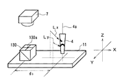
本発明の実施形態を以下に図面に従って説明する。図1は本発明の実施形態に係るワイヤボンディング装置を示す。図示のように、XYテーブル1に搭載されたボンディングヘッド2にはボンディングアーム3が設けられ、ボンディングアーム3は図示しない上下駆動手段で上下方向(すなわちZ方向)に駆動される。ボンディングアーム3の先端部にはツール4が取り付けられ、ツール4にはワイヤ5が挿通されている。またボンディングヘッド2にはカメラホルダ6が固定されており、カメラホルダ6の先端部には、電荷結合素子(CCD)を備えた光電変換式の撮像器である位置検出用カメラ7が固定されている。位置検出用カメラ7の光軸7a、およびツール4の軸心4aはいずれも垂直に上下方向、すなわちZ方向に向かっている。光軸7aと軸心4aはXY方向にオフセット量Xt、Ytだけオフセットされている。XYテーブル1は、その近傍に設置された図示しない2個のパルスモータによりX方向およびY方向に正確に移動できるように構成されており、これにより位置検出用カメラ7とツール4とが、オフセット量Xt、Ytを維持したまま、一体的にX方向およびY方向に移動する。これらは周知の構造である。
【0017】
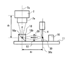
図示しない半導体デバイスを位置決め載置するボンディングステージ10の近傍にレール13が設けられており、レール13の上面には、リファレンス部材30が立設されたリファレンス台11が固定されている。リファレンス台11には、プリズム18、基準パターン用の光源としてのレーザダイオード15、および透過光光源としてのレーザダイオード16が設置されている。
【0018】
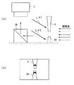
レーザダイオード15は、図2に示すように、リファレンス台11上に設けられた光源台14の上端に、水平方向に対し下45度の傾斜角をもって固定されており、基準パターンLをツール4の先端部に向けて投影する。
【0019】
基準パターンLとしては、図3(b)に示すような水平方向の直線のパターンが用いられる。したがって、図3(a)においてツール4がAの位置にある場合には、基準パターンLは図3(c)のようにツール4の中ほどに投影され、また、ツール4がBの位置にある場合には、基準パターンLは図3(d)のようにツール4の下端部付近に投影される。このように、基準パターンLを水平方向に対して傾斜角をもって投影することに起因して、基準パターンLはツール4のX方向の位置に応じて異なる高さ位置に投影されることとなる。
【0020】
レーザダイオード16は、リファレンス部材30に向けて平行光を照射するように設定されている。プリズム18の反射面18aは、水平方向に対して45°の角度で交差している。したがって、ツール4をリファレンス部材30に近接させた姿勢において、ツール4の下端とリファレンス部材30の上端との光像は、レーザダイオード16の光に対する影として、プリズム18の反射面18aを経て位置検出用カメラ7に導かれる。なお、プリズム18に代えてミラー等の鏡面体を用いてもよい。
【0021】
プリズム18の反射面の中心18bとリファレンス部材30の軸心30aとの間隔d2は、位置検出用カメラ7の光軸7aとツール4の軸心4aとのX方向のオフセット量Xtと略等しくする。
【0022】
位置検出用カメラ7は、テレセントリックレンズであるレンズ7bを備える。ここにいうテレセントリックレンズとは、テレセントリック光学系、すなわち結像する主光線がレンズの後側焦点を通るように構成した光学系をいう。テレセントリックレンズは、結像面への対向方向の位置ずれに対する許容範囲が広く、特に平行光である透過光で照射した場合に物体位置が変動しても像の大きさ(すなわち、光軸からの距離)が変化しないことで一般に知られており、各種の工業用測定器において採用されているが、ボンディング装置においてもテレセントリックレンズか、テレセントリックに近い特性を有する光学系が広く用いられている。
【0023】
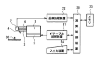
図4に示すように、XYテーブル1は、演算制御装置20の指令によりXYテーブル制御装置21を介して駆動される。位置検出用カメラ7により撮像した画像は、電気信号に変換されて画像処理装置22により処理され、コンピュータよりなる演算制御装置20によって後述する方法により正確なオフセット量Xt、Ytが算出される。メモリ23には予めオフセット量Xw、Ywが記憶されている。そこで、正確なオフセット量Xt、Ytとメモリ23に予め記憶されたオフセット量Xw、Ywとの差、すなわちオフセット較正量をΔX、ΔYとすると、これら正確なオフセット量Xt、Yt、予め記憶されたオフセット量Xw、Yw、およびオフセット較正量ΔX、ΔYは数1の関係になる。なお、図中24は入出力装置を示す。
【0024】
【数1】
Xt=Xw+ΔX
Yt=Yw+ΔY
次に、オフセット量Xt、Ytの算出方法を説明する。まず、図5中実線で示すように、ツール4の軸心4aがリファレンス部材30の近傍に位置するように、演算処理装置20(図4)の指令によりXYテーブル制御装置21を介してXYテーブル1を駆動し、ツール4をリファレンス部材30すれすれの高さまで下降させる。ここで、ツール4は、位置検出用カメラ7がツール4およびリファレンス部材30を撮像できる位置であればよく、リファレンス部材30の軸心30aにツール4の軸心4aを一致させる必要はない。
【0025】
そして、位置検出用カメラ7によりツール4およびリファレンス部材30の両方を撮像し、両者の位置関係、すなわちΔX1、ΔY1を測定する。
【0026】
ここで、レーザダイオード16の照射により、ツール4およびリファレンス部材30の像光が、レーザダイオード16の光に対する影として、プリズム18の反射面18aで反射して位置検出用カメラ7に導かれる。その結果、位置検出用カメラ7では図6のとおりの像が得られる。ここで、この画像に適宜の画像処理を施すことにより、ツール4とリファレンス部材30の輪郭の位置座標に基づいて、両者のずれ量、すなわちツール4の軸心4aとリファレンス部材30の軸心30aとのY方向のずれ量ΔY1が算出される。
【0027】
他方、レーザダイオード15から投影された基準パターンLは、上述のとおり、XYテーブルの平面内の基準位置からのツール4のX方向の位置に応じて、ツール4の軸心方向に沿って異なる高さ位置に投影されることとなる。ここで、ツール4の輪郭と基準パターンLの輪郭と基準パターンLのXYテーブルの平面に対する傾斜角度とに基づいて、XYテーブルの平面内の基準位置からのツール4のX方向の位置と、基準パターンLのツール4上における投影のツール4の軸心方向に沿った高さ位置との関係を求めることができる。したがって、図6におけるツール4の軸心方向に沿った基準パターンLの高さを示す画像に適宜の画像処理を施すことにより、XYテーブルの平面内の基準位置からのツール4のX方向の位置が求められる。ここで、リファレンス部材30の軸心30aの位置をXYテーブルの平面内の基準位置とすることで、ツール4の軸心4aとリファレンス部材30の軸心30aとのX方向のずれ量ΔX1が算出される。
【0028】
このようにしてツール4とリファレンス部材30との位置関係すなわちΔX1、ΔY1が測定されると、次に演算制御装置20は、メモリ23に予め記憶されたオフセット量Xw、Ywにより、XYテーブル制御装置21を介してXYテーブル1を駆動し、図5において点線で示すように、位置検出用カメラ7をリファレンス部材30の近傍に移動させる。そして、この状態でリファレンス部材30を撮像し(図7)、その画像に適宜の画像処理を施すことにより、リファレンス部材30の軸心30aと、位置検出用カメラ7の光軸7aとのずれ量ΔX2、ΔY2を算出する。
【0029】
もし、予め記憶されたオフセット量Xw、Ywが正確なオフセット量Xt、Ytであれば、オフセット較正量ΔX、ΔYは0であるので、ΔX1,ΔY1はΔX2,ΔY2に一致する筈である。しかし、予め記憶されたオフセット量Xw、Ywが大体の値であった場合、またカメラホルダ6やボンディングアーム3が熱的影響により膨張し、オフセット量Xt、Ytが変化した場合には、ΔX1,ΔY1はΔX2,ΔY2に一致せず、誤差(オフセット較正量)ΔX、ΔYが生じる。そこで、測定値ΔX1、ΔY1と測定値ΔX2、ΔY2とにより、数2によりオフセット較正量ΔX、ΔYを算出する。
【0030】
【数2】
ΔX=ΔX1−ΔX2
ΔY=ΔY1−ΔY2
そこで、演算制御装置20は数2によりオフセット較正量ΔX、ΔYを算出し、数1により予め記憶されたオフセット量Xw、Ywにオフセット較正量ΔX、ΔYを加算して正確なオフセット量Xt、Ytを算出し、メモリ23に記憶されたオフセット量Xw、Ywを正確なオフセット量Xt、Ytに補正(更新)する。このようにして求められたオフセット量Xw、Ywは、以後のボンディング作業において位置検出用カメラ7とツール4のオフセット量として用いられる。
【0031】
このように、本実施形態では、所定位置に配置されたレーザダイオード15から水平方向に対する傾斜角をもって基準パターンLをツール4に向けて投影すると共に、ツール4に投影された基準パターンLに基づいてツール4のX方向の位置を測定する。このため、ツール4の位置に応じて基準パターンLは異なる高さ位置に投影されることとなり、これに基づいてツール4のX方向の位置の検出を正確に実行できる。
【0032】
また、位置検出用カメラ7の位置の測定を、位置検出用カメラ7でリファレンス部材30を撮像することにより実行することとしたので、本来半導体デバイスを撮像するためのものである位置検出用カメラ7をオフセット量の測定に利用できる。
【0033】
また、位置検出用カメラ7の位置をリファレンス部材30を基準として測定し、ツール4のY方向の位置をリファレンス部材30を基準として測定すると共に、これらの測定値と、両測定の間の位置検出用カメラ7およびツール4の移動量である予め記憶されたオフセット量Xw、Ywとに基づいてオフセット量を求めることとしたので、リファレンス部材30を介することによりオフセット量の測定をきわめて正確に実行できる。
【0034】
また、ツール4とリファレンス部材30との像光を位置検出用カメラ7に導くプリズム18を設けたので、位置検出用カメラ7を、位置検出用カメラ7自体の位置の検出のみならず、ツール4の位置の検出にも利用できる。
【0035】
さらに、ツール4の位置の測定に関し、ツール4に投影された基準パターンLに基づいてツール4の位置を測定したX方向の測定値と、ツール4およびリファレンス部材30の像光を位置検出用カメラ7に導いてツール4とリファレンス部材30との位置関係を位置検出用カメラ7により測定したY方向の測定値とを用いることとしたので、一般にずれ量の比較的大きいY方向の測定を、比較的視野の広いツール4の輪郭の画像に基く方法で行えると共に、ずれ量の比較的小さいX方向の測定を基準パターンLの像に基づいて精度よく行うことができる。
【0036】
なお、本実施形態のように、ツール4のX方向の位置の測定をツール4に投影された基準パターンLに基づいて行う一方、ツール4のY方向の位置の測定をツール4の輪郭の画像に基づいて行う構成のほか、ツール4の測定をX方向・Y方向共に基準パターンの投影によって行う構成とすることもでき、この場合には、例えばレーザダイオード15と同様に水平方向に対して所定の傾斜角を持った光源をリファレンス部材30に対してY方向に設けると共に、リファレンス部材30をY方向から専用のカメラで撮像すればよく、さらには、リファレンス部材30をY方向からみた光像を位置検出用カメラ7に導く光学部材を設けてもよい。
【0037】
また、本実施形態では、レーザダイオード15の照射方向を、水平方向に対し斜め下方としたが、逆に測定姿勢におけるツール4の位置に対し斜め下方にレーザダイオード15を設置し斜め上方にツール4を照射する構成としてもよい。
【0038】
また、本実施形態では、レーザダイオード15の照射方向を、水平方向に対し下45度としたが、レーザダイオード15の照射方向は他の角度でもよく、傾斜角が大きいほど高い測定精度を得ることができる。また、本実施形態ではツール4のX方向のずれ量の測定をツール4を水平方向からみた光像に基づいて行う構成としたので、画像処理にあたりX座標への変換が容易であるという利点があるが、レーザダイオード15による照射方向と画像の検出方向とが互いに異なるのであれば同様の方法によるツール4のX方向のずれ量の測定が可能であり、例えば基準パターンLの照射方向を水平方向とする一方、ツール4のX方向のずれ量の測定をツール4を水平方向とは異なる角度からみた光像に基づいて行う構成としてもよい。
【0039】
また、本実施形態では、レーザダイオード15を光源台14を介してリファレンス台11に固定する構成としたが、レーザダイオード15は他の任意の位置に設置することができ、特に、位置検出用カメラ7に固定する構成としてもよい。
【0040】
また、本実施形態ではレーザダイオード16により透過光照明を行う構成としたが、ツール4の輪郭の画像に基づく位置の測定については反射光を使用してもよく、例えば位置検出用カメラ7に光源を内蔵してプリズム18を介してツール4を照明する構成としてもよい。また、本実施形態では平行光を生ずるように設定されたレーザダイオード16を用いる構成としたが、このような構成に代えて、ピンホールとレンズとを任意の光源と組み合わせ、これにより平行光を得る構成としてもよい。この場合の光源としては、例えばLED(発光ダイオード)、ハロゲンランプ、タングステンランプ、あるいは光ファイバの出射口などが好適である。ピンホールはなくてもよいが、ピンホールを用いない場合には光線の平行度は劣ることとなる。
【0041】
また、本実施形態では基準パターンLを水平方向の直線のパターンとしたが、基準パターンLは他の構成でもよく、例えば図8(a)のようなスポット光、図8(b)のようなゼブラパターン、図8(c)のような格子パターン、図8(e)のようなカラーパターンなどを用いてもよい。また、図8(d)のような正弦パターン、すなわち光強度が正弦分布であるパターンを用いてもよく、この場合には位相を120度ずつ異にしたパターンを照明した撮像を3回実行してこれらの画像を重ね合わせることにより、ツール4の表面の傷や汚れの影響をキャンセルして精度よく測定を行うことができる。
【0042】
また、本実施形態のように、位置検出用カメラ7を、ツール4およびリファレンス部材30の撮像に兼用する場合、ボンディング部品から位置検出用カメラ7までの距離が、ツール4およびリファレンス部材30から位置検出用カメラ7までの距離と異なることに起因して、後者の像の大きさが変化し、その結果ツール4とリファレンス部材30との位置関係が正しく検出できないことが考えられる。この点本実施形態では、被写体位置が変動しても像の大きさが変化しない特性をもつテレセントリックレンズであるレンズ7bを位置検出用カメラ7に備えたので、これらの撮像に基づく位置関係の検出をいずれも正確に実行することができ好適である。
【0043】
また、本実施形態では、ツール4およびリファレンス部材30を、X方向およびY方向から、すなわち互いに90°角度を異にして捉えた像を用いて、両者のずれ量を測定する構成としたが、両者の相対角度は90°でなくてもよい。また、リファレンス部材を設ける位置は、本実施形態で示す位置に限られず、ボンディング部品にできるだけ近い位置とするのが好適であり、さらには、ボンディング部品自体(例えばリードフレーム)の何らかの突起をリファレンス部材として利用してもよい。
【0044】
また、本実施形態では、ツール4とリファレンス部材30との位置関係を測定してからツール4と位置検出用カメラ7とを移動して位置検出用カメラ7とリファレンス部材30との位置関係を測定する構成としたが、両測定の順番は逆であってもよく、かかる構成も本発明の範疇に含まれるものである。
【0045】
なお、本実施形態ではツール4およびリファレンス部材30の光像をそのままプリズム18を経て位置検出用カメラ7に導く構成としたが、図9に示すように、プリズム18とリファレンス部材30との間に、補正レンズ50を備える構成としてもよい。補正レンズ50は補正レンズ支持台52によりリファレンス台11に固定されている。レンズ7eのみが用いられた場合のピント位置は、位置検出用カメラ7の結像面から距離d1だけ離れたプリズム18の反射面18aの中心18bである。また、レンズ7eと補正レンズ50との両者が用いられた場合のピント位置は、位置検出用カメラ7の結像面から距離d1+d2だけ離れたリファレンス部材30の軸心30aである。位置検出用カメラ7に装着されたレンズ7eはテレセントリックレンズでなくてもよい。なお本変形例においても、図2の構成と同様に光源台14およびレーザダイオード15を設置しているが、図9では図示を省略している。
【0046】
しかしてこの変形例では、位置検出用カメラ7により、補正レンズ50およびプリズム18を介して、ツール4およびリファレンス部材30の両方を撮像する。この場合のピント位置までの距離は、補正レンズ50を介しているのでd1+d2となる。次に位置検出用カメラ7を移動してリファレンス部材30に近接させ、その状態で位置検出用カメラ7によりリファレンス部材30を直接撮像する。この場合のピント位置までの距離は、補正レンズ50を介していないのでd1となる。このように、この変形例では、リファレンス台11ひいてはリファレンス部30と一体的に保持された補正レンズ50により、ピント位置までの距離を変更する構成としたので、ツール4およびリファレンス部材30を撮像する姿勢へ移動する動作に伴って補正レンズ50が光路中に介装されることとなり、位置検出用カメラ7によりツール4およびリファレンス部材30の両方を撮像する場合と、位置検出用カメラ7によりリファレンス部材30を直接撮像する場合との間で、機械的・電気的手段による位置検出用カメラ7の焦点合わせ操作が不要であるという利点がある。
【0047】
次に、参考実施形態について説明する。上記第1実施形態では、ツール4とリファレンス部材30との位置関係の測定と、位置検出用カメラ7とリファレンス部材30との位置関係の測定との間で、ツール4と位置検出用カメラ7とを移動させ、この移動量を加算してオフセット量を求める構成としたため、両測定の共通の基準点であるリファレンス部材30を介してオフセット量をきわめて正確に測定できる利点があるが、両測定の間でツール4と位置検出用カメラ7とを移動させない(すなわち、移動量をゼロとする)構成とすることも可能である。すなわち、図10に示すように、上面にリファレンスマーク130aを設けたプリズム130をリファレンス台11上に設け、他方、位置検出用カメラ7をリファレンスマーク130aの真上に配置した場合においてツール4をX方向およびY方向からそれぞれ斜め下向きに基準パターンLx,Lyを照射するような位置に、図2と同様の光源台14およびレーザダイオード15(図示せず)をそれぞれ配置する。リファレンスマーク130aとレーザダイオード15の撮像基準位置とのX方向のずれ量d3は、予め記憶されているオフセット量Xwと等しくし、また、Y方向のずれ量はゼロとする。なお、この構成において図9の補正レンズ50と同様の補正レンズを設けてもよい。
【0048】
しかして、この構成では、位置検出用カメラ7によりリファレンスマーク130aを撮像し、これを電気信号に変換して画像処理を施すことによりずれ量ΔX1,ΔY1を求める。次に、その状態で位置検出用カメラ7によりプリズム130を介してツール4を撮像し、撮像した画像におけるツール4の輪郭の画像とツール4上に投影された基準パターンの画像とに基づいて画像処理を施すことにより、ずれ量ΔX2,ΔY2を求める。そしてこれらのずれ量と、リファレンスマーク130aとレーザダイオード15の撮像基準位置とのずれ量から上記数1および数2により正確なオフセット量を算出する。
【0049】
この構成によれば、位置検出用カメラ7の位置の測定とツール4の位置の測定との間で、位置検出用カメラ7とツール4とを移動する必要がないため、オフセットの補正を迅速に実行できる利点がある。なお、この構成では、測定にリファレンスマーク130aとレーザダイオード15の撮像基準位置との位置関係の狂いが含まれるものではあるが、両者の位置関係に狂いが出にくい構成とし、かつ定期的に両者の位置関係を較正することにより、誤差を最小限に抑えることが可能である。
【0050】
次に、別の参考実施形態について説明する。この別の参考実施形態は、図11(a)に示すように、ツール4およびリファレンス部材30の両方に、共通の光源であるレーザダイオード(図示せず)から基準パターンLx1,Lx2を斜め下向きに投影するものである。基準パターンLx1,Lx2はそれぞれ別個の光源から投影してもよいが、その場合には両光源の間隔および角度は精密に設定されている必要がある。なお、この構成において図9の補正レンズ50と同様の補正レンズを設けてもよい。
【0051】
しかして、この構成では、位置検出用カメラ7によりプリズム18を介してツール4およびリファレンス部材30を撮像すると、ツール4上に投影された基準パターンLx1と、リファレンス部材30に投影された基準パターンLx2との画像、すなわち図11(b)に示されるような画像が得られる。この画像に画像処理を施すことによりツール4とリファレンス部材30とのずれ量ΔX2,ΔY2を求め、これに基づいて正確なオフセット量を算出する。
【0052】
このように、この別の参考実施形態では、ツール4とリファレンス部材30の両方に対して基準パターンLx1,Lx2を投影し、これらの像に基づいてツール4の位置を測定するので、リファレンス部材30と光源との位置関係に基づいて、ツール4と光源との位置関係の測定値を補正でき、リファレンス部材30とツール4との位置関係を一層精度よく求めることができる。
【0053】
次に、他の参考実施形態について説明する。この他の参考実施形態は、図12に示すように、上面に図10のものと同様のリファレンスマーク130aを設けたプリズム130をリファレンス台11上に設け、他方、位置検出用カメラ7をリファレンスマーク130aの真上に配置した場合においてツール4の軸心4aを囲むリファレンス台11上の位置に、リング状光源115を設置し、このリング状光源115は、全周からツール4の長手方向の中ほどである撮像基準位置に、基準パターンL3を斜め上向きに投影するように設定する。なお、この構成において図9の補正レンズ50と同様の補正レンズを設けてもよい。
【0054】
しかして、この構成では、位置検出用カメラ7によりプリズム130を介してツール4を撮像し、撮像した画像におけるツール4の輪郭の画像とツール4上に投影された基準パターンL3の画像とに基づいて画像処理を施すことにより、ずれ量ΔX2,ΔY2を求め、これに基づいて正確なオフセット量を算出する。
【0055】
ここで、ツール4の撮像によって得られる画像は、ツール4の軸心4aの位置によって異なり、リング状光源115の中心115aとツール4の軸心4aとが一致している場合には図13(a)のとおりとなるが、それぞれ、ツール4の軸心4aがY方向にずれている場合には図13(b)、−Y方向にずれている場合には図13(c)、−X方向にずれている場合には図13(d)、X方向にずれている場合には図13(e)のとおりとなる。このような画像の変化に基づき、この他の参考実施形態ではツール4の位置を正確に求めることができる。
【0056】
次に、さらに他の参考実施形態について説明する。図14に示すさらに他の参考実施形態は、上記図10の参考実施形態と同様に、XY2方向から、図3(b)に示すものと同様の水平のライン状である基準パターンL4,L5をツール4に投影するものであるが、投影方向が斜め上向きである点で上記図10の参考実施形態と異なる。なお光源は図14においても図示省略している。
【0057】
しかして、この構成におけるツール4の撮像によって得られる画像は、ツール4の軸心4aの位置によって異なり、ツール4の軸心4aが撮像基準位置にある場合には図15(a)のとおりとなるが、それぞれ、ツール4の軸心4aがY方向にずれている場合には図15(b)、−Y方向にずれている場合には図15(c)、−X方向にずれている場合には図15(d)、X方向にずれている場合には図15(e)のとおりとなる。このような画像の変化に基づき、さらに他の参考実施形態ではツール4の位置を正確に求めることができる。
【0058】
なお、上記各実施形態では、本発明における処理部材を単独のツール4とした場合について説明したが、本発明は複数の加工ヘッドと位置検出用撮像器とのオフセット量の測定や、これら複数の加工ヘッド相互間のオフセット量の測定について適用することも可能である。
【0059】
また、上記実施形態では光学部材としてプリズム18,130を用いる構成としたが、本発明における光学部材は、処理部材およびリファレンス部材(あるいはリファレンスマーク)の像光を位置検出用撮像器に導きうる構成であればよく、例えば処理部材に対し互いに角度を異にして対向するように配置された光ファイバであってもよい。また、上記実施形態では撮像器としてカメラを用いたが、本発明における撮像器は光を検出しうる構成であればよく、例えばラインセンサでもよい。また上記実施形態では、本発明をワイヤボンディング装置に適用した場合について説明したが、本発明をダイボンディング装置、テープボンディング装置、フリップチップボンディング装置などの他の各種のボンディング装置に適用できることは勿論である。
【図面の簡単な説明】
【図1】 第1実施形態に係るボンディング装置の要部を示す斜視図である。
【図2】 第1実施形態の要部を示す正面図である。
【図3】 基準パターンの照射についての説明図であり、(a)は照射方向とツールの位置、(b)は基準パターンの例、(c)および(d)は基準パターンが照射されたツールの光像である。
【図4】 第1実施形態の制御系を示すブロック図である。
【図5】 オフセット補正におけるツール、位置検出用カメラおよびリファレンス部材の配置状態を示す平面図である。
【図6】 ツールをリファレンス部材に近接させた姿勢における画像を示す説明図である。
【図7】 位置検出用カメラをリファレンス部材に近接させた姿勢における画像を示す説明図である。
【図8】 (a)ないし(e)は基準パターンの他の構成例を示す説明図である。
【図9】 光学系の変形例を示す正面図である。
【図10】 参考実施形態の要部を示す斜視図である。
【図11】 別の参考実施形態を示し、(a)は要部を示す正面図、(b)はツールの光像である。
【図12】 他の参考実施形態の要部を示す説明図である。
【図13】 (a)ないし(e)は他の参考実施形態におけるツールの画像を示す説明図である。
【図14】 さらに他の参考実施形態の要部を示す斜視図である。
【図15】 (a)ないし(e)はさらに他の第5実施形態におけるツールの画像を示す説明図である。
【符号の説明】
1 XYテーブル、2 ボンディングヘッド、3 ボンディングアーム、4 ツール、4a 軸心、7 位置検出用カメラ、7a 光軸、11 リファレンス台、18,130 プリズム、15,16 レーザダイオード、30 リファレンス部材、30a 軸心、50 補正レンズ。[0001]
BACKGROUND OF THE INVENTION
The present invention relates to an offset measurement method, a tool position detection method, and a bonding apparatus, and more particularly, to a method and apparatus capable of accurately calculating an offset amount between a position detection imager that images a bonding component and a processing member such as a tool.
[0002]
[Prior art]
Hereinafter, a wire bonding apparatus will be described as an example. A bonding head mounted on an XY table includes a position detection camera for imaging a reference pattern on a bonding component and a bonding tool for specifying a bonding point on the bonding component such as a semiconductor device. And a bonding arm attached to the. When the position detection camera images the reference pattern on the bonding part, the optical axis of the position detection camera and the axis of the tool are arranged so that the tool and the bonding arm do not interfere with the visual field of the position detection camera. Are assembled to the bonding head with a certain distance. In general, the distance between the optical axis of the position detection camera and the axis of the tool is called an offset.
[0003]
Since the position detection camera obtains a reference point for knowing the position where the tool is moved, it is very important to know how much the position detection camera is offset from the tool. However, the actual offset amount changes with the thermal expansion of the camera holder and bonding arm due to radiant heat from the high-temperature bonding stage, so the offset amount is calibrated at the beginning of the bonding operation and at appropriate timing between operations. There is a need to.
[0004]
For this purpose, conventionally, an indentation is made with a tool at an appropriate location within the bonding range, and the position of the indentation is detected by a position detection camera, whereby the position of the tool is detected, and the offset amount is calibrated based on the detected position. A method has been proposed (for example, JP 59-69939 A). In this method, predetermined image processing is performed on the photoelectrically converted image data from the position detection camera to obtain the coordinates of the center of the indentation, and the offset amount is calculated based on this.
[0005]
[Problems to be solved by the invention]
However, this conventional configuration has a problem that the impression of the tool is not always clear and the shape of each impression is different from that of a dedicated pattern suitable for image processing, so that detection is not always accurate.
[0006]
The present invention has been made to solve the above-described problems, and an object thereof is to provide a novel means capable of accurately detecting the position of a tool.
[0007]
[Means for Solving the Problems]
A bonding apparatus according to the present invention includes a position detection image pickup device that picks up an image of a bonding component, a tool that is provided offset from the position detection image pickup device and processes the bonding component, the position detection image pickup device, and the position detection image pickup device. In a bonding apparatus provided with an XY table for integrally moving a tool, the reference pattern is disposed at a predetermined position associated with a reference position in the plane of the XY table and has a predetermined inclination angle with respect to the plane of the XY table. A light source that projects the light toward the tool, and an optical that guides the image light of the reference member and the image light of the tool installed at a predetermined position associated with the reference position in the plane of the XY table to the image sensor for position detection. A first member wherein the tool is moved closer to the reference member by moving the XY table. A measurement value obtained by measuring the position of the tool based on a position along the axial direction of the tool of the reference pattern projected onto the tool in the placed state, and the tool and the reference member in the first placed state. A measurement value obtained by measuring the positional relationship associated with a reference position in the XY plane between the tool and the reference member by guiding the image light to the position detection image sensor, and the position detection image sensor; In the second arrangement state in which the image pickup device is brought close to the reference member by moving the XY table, the positional relationship associated with the reference position in the XY plane between the position detection image pickup device and the reference member is the position. Between the measurement value measured by the image pickup device for detection and the position detection image pickup device between the first arrangement state and the second arrangement state; Comprising a moving amount of the tool, the arithmetic and control unit for obtaining the offset amount in the XY plane based on.
In addition, the offset method according to the present invention includes a position detection image pickup device that picks up an image of a bonding component, a tool that is provided offset from the position detection image pickup device and processes the bonding component, and the position detection image pickup device. And an XY table for integrally moving the tool, an offset measurement method executed in which a light source is arranged at a predetermined position associated with a reference position in the plane of the XY table, and the XY table Projecting a reference pattern toward the tool with a predetermined inclination angle with respect to the plane of the plane, and the tool in the first arrangement state in which the tool is brought close to the reference member by moving the XY table. The position of the tool is determined based on the position of the projected reference pattern along the axial direction of the tool. And in the first arrangement state, using the optical member, the image light of the reference member and the image light of the tool installed at a predetermined position associated with the reference position in the plane of the XY table are A step of leading to a position detection imager, measuring the positional relationship of the tool and the reference member associated with a reference position in the XY plane by the position detection imager; and the position detection imager, In the second arrangement state, the optical member is used to move the image light of the reference member and the image light of the tool in a second arrangement state in which the XY table is moved close to the reference member. The position detection imaging device is guided to the position detection imaging device, and the positional relationship between the position detection imaging device and the reference member is related to a reference position in the XY plane. A step of measuring with a measuring instrument, a measurement value of the position of the tool, a positional relationship associated with a reference position in the XY plane of the tool and the reference member in the first arrangement state, and in a second arrangement state The positional relationship between the tool and the reference member associated with the reference position in the XY plane, and the movement amount of the position detection image pickup device and the tool between the first arrangement state and the second arrangement state And calculating an offset amount in the XY plane based on.
[0008]
Associated with a reference position in the reference planeFrom a light source placed in place, Against the reference planeProject a reference pattern onto a tool with a predetermined tilt angleWhen,The reference pattern projected on the tool is detected as a different position or shape depending on the position of the tool, and thus the position of the tool can be accurately detected.
[0010]
Also,Reference materialIs installed at a predetermined position associated with the reference position in the reference plane.SoBy using the reference member, the measurement of the position of the tool and the position of the image sensor for position detection can be performed very accurately.
[0012]
Also,Optical memberGuides the image light of the tool and the reference member to the position detecting image pickup device.SoThe position detection image pickup device for picking up an image of the processing target is suitable not only for detecting the position of the position detection image pickup device but also for detecting the position of the tool.
[0013]
Further, regarding the measurement of the position of the tool, the measurement value obtained by measuring the position of the tool based on the reference pattern projected onto the tool and the image light of the tool and the reference member are guided to the position detection image pickup device. If the measured value obtained by measuring the positional relationship between the tool and the reference member with the position detecting imager is used, the position of the tool can be obtained more accurately.
[0016]
DETAILED DESCRIPTION OF THE INVENTION
Embodiments of the present invention will be described below with reference to the drawings. FIG. 1 shows a wire bonding apparatus according to an embodiment of the present invention. As shown in the figure, a
[0017]
A
[0018]
As shown in FIG. 2, the
[0019]
As the reference pattern L, a horizontal straight line pattern as shown in FIG. Therefore, when the
[0020]
The
[0021]
The distance d2 between the center 18b of the reflecting surface of the
[0022]
The
[0023]
As shown in FIG. 4, the XY table 1 is driven via the XY
[0024]
[Expression 1]
Xt = Xw + ΔX
Yt = Yw + ΔY
Next, a method for calculating the offset amounts Xt and Yt will be described. First, as indicated by the solid line in FIG. 5, the XY table is set via the XY
[0025]
Then, both the
[0026]
Here, by the irradiation of the
[0027]
On the other hand, the reference pattern L projected from the
[0028]
In this way, the positional relationship between the
[0029]
If the offset amounts Xw and Yw stored in advance are accurate offset amounts Xt and Yt, the offset calibration amounts ΔX and ΔY are 0, so ΔX1, ΔY1Is ΔX2, ΔY2It should be consistent with However, if the offset amounts Xw and Yw stored in advance are approximate values, or if the
[0030]
[Expression 2]
ΔX = ΔX1-ΔX2
ΔY = ΔY1-ΔY2
Therefore, the arithmetic and
[0031]
As described above, in the present embodiment, the reference pattern L is projected toward the
[0032]
Further, since the position of the
[0033]
Further, the position of the
[0034]
Further, since the
[0035]
Further, regarding the measurement of the position of the
[0036]
Note that, as in this embodiment, the position of the
[0037]
In this embodiment, the irradiation direction of the
[0038]
In this embodiment, the irradiation direction of the
[0039]
In the present embodiment, the
[0040]
In the present embodiment, the transmitted light illumination is performed by the
[0041]
Further, in the present embodiment, the reference pattern L is a horizontal straight line pattern, but the reference pattern L may have another configuration, for example, spot light as shown in FIG. 8A or as shown in FIG. 8B. A zebra pattern, a lattice pattern as shown in FIG. 8C, a color pattern as shown in FIG. Further, a sine pattern as shown in FIG. 8D, that is, a pattern having a sine distribution of light intensity may be used. In this case, imaging with illumination of a pattern whose phase is different by 120 degrees is executed three times. By superimposing these images, the influence of scratches and dirt on the surface of the
[0042]
When the
[0043]
In the present embodiment, the
[0044]
In this embodiment, the positional relationship between the
[0045]
In the present embodiment, the optical images of the
[0046]
In this variation, however, both the
[0047]
next,referenceEmbodiments will be described. In the first embodiment, between the measurement of the positional relationship between the
[0048]
In this configuration, the
[0049]
According to this configuration, it is not necessary to move the
[0050]
next,Another referenceEmbodiments will be described. thisAnother referenceIn the embodiment, as shown in FIG. 11A, a reference pattern L is formed from a laser diode (not shown) that is a common light source for both the
[0051]
Thus, in this configuration, when the
[0052]
in this way,This another referenceIn the embodiment, the reference pattern L for both the
[0053]
next,Other referencesEmbodiments will be described.Other referencesIn the embodiment, as shown in FIG. 12, a
[0054]
Thus, in this configuration, the
[0055]
Here, the image obtained by imaging of the
[0056]
next,Other referencesEmbodiments will be described. As shown in FIG.Other referencesEmbodiments aboveReference to Figure 10As in the embodiment, the reference pattern L is a horizontal line similar to that shown in FIG. 3B from the XY2 direction.4, L5Is projected onto the
[0057]
Thus, an image obtained by imaging of the
[0058]
In each of the above embodiments, the case where the processing member according to the present invention is a
[0059]
In the above embodiment, the
[Brief description of the drawings]
FIG. 1 is a perspective view showing a main part of a bonding apparatus according to a first embodiment.
FIG. 2 is a front view showing a main part of the first embodiment.
FIGS. 3A and 3B are diagrams illustrating irradiation of a reference pattern, where FIG. 3A is an irradiation direction and a tool position, FIG. 3B is an example of a reference pattern, and FIGS. 3C and 3D are tools irradiated with a reference pattern; It is a light image.
FIG. 4 is a block diagram showing a control system of the first embodiment.
FIG. 5 is a plan view showing an arrangement state of a tool, a position detection camera, and a reference member in offset correction.
FIG. 6 is an explanatory diagram showing an image in a posture in which a tool is brought close to a reference member.
FIG. 7 is an explanatory diagram showing an image in a posture in which a position detection camera is brought close to a reference member.
FIGS. 8A to 8E are explanatory views showing other configuration examples of the reference pattern.
FIG. 9 is a front view showing a modification of the optical system.
FIG. 10referenceIt is a perspective view which shows the principal part of embodiment.
FIG. 11Another referenceEmbodiment is shown, (a) is a front view which shows the principal part, (b) is the optical image of a tool.
FIG.Other referencesIt is explanatory drawing which shows the principal part of embodiment.
[Fig. 13] (a) to (e)Other referencesIt is explanatory drawing which shows the image of the tool in embodiment.
FIG. 14Other referencesIt is a perspective view which shows the principal part of embodiment.
FIG. 15 (a) to (e)Yet anotherIt is explanatory drawing which shows the image of the tool in 5th Embodiment.
[Explanation of symbols]
1 XY table, 2 bonding head, 3 bonding arm, 4 tool, 4a axis, 7 position detection camera, 7a optical axis, 11 reference base, 18, 130 prism, 15, 16 laser diode, 30 reference member, 30a axis Heart, 50 correction lens.
Claims (2)
XYテーブルの平面内の基準位置に関連付けられる所定位置に配置され、XYテーブルの平面に対して所定の傾斜角をもって、基準パターンを前記ツールに向けて投影する光源と、A light source arranged at a predetermined position associated with a reference position in the plane of the XY table, and projecting a reference pattern toward the tool with a predetermined inclination angle with respect to the plane of the XY table;
XYテーブルの平面内の基準位置に関連付けられる所定位置に設置されたリファレンス部材の像光と前記ツールの像光とを前記位置検出用撮像器に導く光学部材と、を備え、An optical member for guiding the image light of the reference member installed at a predetermined position associated with the reference position in the plane of the XY table and the image light of the tool to the image sensor for position detection;
前記ツールを、前記XYテーブルの移動により前記リファレンス部材に近接させた第一の配置状態において前記ツールに投影された前記基準パターンのツールの軸心方向に沿った位置に基づいて前記ツールの位置を測定した測定値と、該第一の配置状態において前記ツールおよび前記リファレンス部材の像光を前記位置検出用撮像器に導いて前記ツールと前記リファレンス部材とのXY平面内の基準位置に関連付けられた位置関係を前記位置検出用撮像器により測定した測定値と、The position of the tool is determined based on the position along the axial direction of the tool of the reference pattern projected onto the tool in the first arrangement state in which the tool is brought close to the reference member by moving the XY table. In the first arrangement state, the measured measurement value and the image light of the tool and the reference member are guided to the position detection image pickup device and associated with the reference position in the XY plane between the tool and the reference member. A measured value obtained by measuring the positional relationship with the position detection imager;
前記位置検出用撮像器を、前記XYテーブルの移動により前記リファレンス部材に近接させた第二の配置状態において前記位置検出用撮像器と前記リファレンス部材とのXY平面内の基準位置に関連付けられた位置関係を前記位置検出用撮像器で測定した測定値と、The position associated with the reference position in the XY plane between the position detection image pickup device and the reference member in the second arrangement state in which the position detection image pickup device is brought close to the reference member by moving the XY table. Measured values measured by the position detection imager, and
前記第一の配置状態と第二の配置状態との間における前記位置検出用撮像器および前記ツールの移動量と、The amount of movement of the position detection imaging device and the tool between the first arrangement state and the second arrangement state,
に基づいてXY平面内におけるオフセット量を求める演算制御装置を備えたボンディング装置。The bonding apparatus provided with the calculation control apparatus which calculates | requires the offset amount in XY plane based on this.
光源をXYテーブルの平面内の基準位置に関連付けられる所定位置に配置し、XYテーブルの平面に対して所定の傾斜角をもって、基準パターンを前記ツールに向けて投影する工程と、Disposing a light source at a predetermined position associated with a reference position in the plane of the XY table, projecting the reference pattern toward the tool with a predetermined tilt angle with respect to the plane of the XY table;
前記ツールを、前記XYテーブルの移動により前記リファレンス部材に近接させた第一の配置状態において前記ツールに投影された前記基準パターンのツールの軸心方向に沿った位置に基づいて前記ツールの位置を測定する工程と、The position of the tool is determined based on the position along the axial direction of the tool of the reference pattern projected onto the tool in the first arrangement state in which the tool is brought close to the reference member by moving the XY table. Measuring process;
該第一の配置状態において、光学部材を用いて、XYテーブルの平面内の基準位置に関連付けられる所定位置に設置されたリファレンス部材の像光と前記ツールの像光とを前記位置検出用撮像器に導き、前記ツールと前記リファレンス部材とのXY平面内の基準位置に関連付けられた位置関係を前記位置検出用撮像器により測定する工程と、In the first arrangement state, the image sensor for position detection uses the optical member to obtain the image light of the reference member and the image light of the tool installed at a predetermined position associated with the reference position in the plane of the XY table. And measuring the positional relationship of the tool and the reference member associated with a reference position in the XY plane with the position detection imager;
前記位置検出用撮像器を、前記XYテーブルの移動により前記リファレンス部材に近接させた第二の配置状態に移動させる工程と、Moving the image sensor for position detection to a second arrangement state close to the reference member by moving the XY table;
第二の配置状態において、光学部材を用いて、前記リファレンス部材の像光と前記ツールの像光とを前記位置検出用撮像器に導き、前記位置検出用撮像器と前記リファレンス部材とのXY平面内の基準位置に関連付けられた位置関係を前記位置検出用撮像器で測定する工程と、In the second arrangement state, an optical member is used to guide the image light of the reference member and the image light of the tool to the position detection image pickup device, and an XY plane between the position detection image pickup device and the reference member. Measuring a positional relationship associated with a reference position within the position detection imager;
前記ツールの位置の測定値と、第一の配置状態における前記ツールと前記リファレンス部材とのXY平面内の基準位置に関連付けられた位置関係と、第二の配置状態における前記ツールと前記リファレンス部材とのXY平面内の基準位置に関連付けられた位置関係と、前記第一の配置状態と第二の配置状態との間における前記位置検出用撮像器および前記ツールの移動量と、に基づいてXY平面内におけるオフセット量を求める工程と、A measurement value of the position of the tool, a positional relationship associated with a reference position in the XY plane between the tool and the reference member in the first arrangement state, and the tool and the reference member in the second arrangement state. XY plane based on the positional relationship associated with the reference position in the XY plane and the amount of movement of the position detection image pickup device and the tool between the first arrangement state and the second arrangement state A step of obtaining an offset amount in the inside,
を含むことを特徴とするオフセット測定方法。An offset measuring method comprising:
Priority Applications (5)
| Application Number | Priority Date | Filing Date | Title |
|---|---|---|---|
| JP2000059843A JP3967518B2 (en) | 2000-03-06 | 2000-03-06 | Offset measurement method, tool position detection method, and bonding apparatus |
| TW089126701A TW475229B (en) | 2000-03-06 | 2000-12-14 | Offset measurement method, tool position detection method and bonding device |
| KR10-2001-0011101A KR100420272B1 (en) | 2000-03-06 | 2001-03-05 | Method for measuring offset, method for detecting tool location, and a bonding apparatus |
| US09/800,323 US6762848B2 (en) | 2000-03-06 | 2001-03-06 | Offset measurement method, tool position detection method and bonding apparatus |
| US10/267,154 US6814121B2 (en) | 2000-03-06 | 2002-10-09 | Bonding apparatus |
Applications Claiming Priority (1)
| Application Number | Priority Date | Filing Date | Title |
|---|---|---|---|
| JP2000059843A JP3967518B2 (en) | 2000-03-06 | 2000-03-06 | Offset measurement method, tool position detection method, and bonding apparatus |
Related Child Applications (1)
| Application Number | Title | Priority Date | Filing Date |
|---|---|---|---|
| JP2007117590A Division JP4467599B2 (en) | 2007-04-26 | 2007-04-26 | Bonding equipment |
Publications (3)
| Publication Number | Publication Date |
|---|---|
| JP2001249007A JP2001249007A (en) | 2001-09-14 |
| JP2001249007A5 JP2001249007A5 (en) | 2005-08-11 |
| JP3967518B2 true JP3967518B2 (en) | 2007-08-29 |
Family
ID=18580243
Family Applications (1)
| Application Number | Title | Priority Date | Filing Date |
|---|---|---|---|
| JP2000059843A Expired - Fee Related JP3967518B2 (en) | 2000-03-06 | 2000-03-06 | Offset measurement method, tool position detection method, and bonding apparatus |
Country Status (4)
| Country | Link |
|---|---|
| US (2) | US6762848B2 (en) |
| JP (1) | JP3967518B2 (en) |
| KR (1) | KR100420272B1 (en) |
| TW (1) | TW475229B (en) |
Families Citing this family (27)
| Publication number | Priority date | Publication date | Assignee | Title |
|---|---|---|---|---|
| JP3967518B2 (en) * | 2000-03-06 | 2007-08-29 | 株式会社新川 | Offset measurement method, tool position detection method, and bonding apparatus |
| JP4620262B2 (en) * | 2001-01-16 | 2011-01-26 | 富士機械製造株式会社 | Electronic component mounting device |
| DE10119018A1 (en) * | 2001-04-18 | 2002-10-24 | Emhart Llc Newark | Positioning and/or mounting aid for devices used for machining components, has arrangement for producing light or laser beam for direction from reference position outside device, especially machining space, to reference point |
| WO2003085723A1 (en) * | 2002-04-04 | 2003-10-16 | Toray Engineering Co., Ltd. | Alignment method and mounting method using the alignment method |
| JP4105926B2 (en) * | 2002-09-30 | 2008-06-25 | 株式会社新川 | Offset measuring mechanism in bonding apparatus and offset measuring method in bonding apparatus |
| JP4128540B2 (en) * | 2003-06-05 | 2008-07-30 | 株式会社新川 | Bonding equipment |
| DE10338809B4 (en) * | 2003-08-21 | 2008-05-21 | Hesse & Knipps Gmbh | Method and device for adjusting bonding head elements |
| JP4088232B2 (en) * | 2003-10-07 | 2008-05-21 | 株式会社新川 | Bonding method, bonding apparatus, and bonding program |
| US20070260420A1 (en) * | 2006-05-03 | 2007-11-08 | Data I/O Corporation | Automated calibration system |
| JP5301329B2 (en) * | 2008-03-31 | 2013-09-25 | Juki株式会社 | Electronic component mounting method |
| JP4247299B1 (en) * | 2008-03-31 | 2009-04-02 | 株式会社新川 | Bonding apparatus and bonding method |
| US7810698B2 (en) * | 2008-11-20 | 2010-10-12 | Asm Assembly Automation Ltd. | Vision system for positioning a bonding tool |
| JP2010256341A (en) * | 2009-03-31 | 2010-11-11 | Toshiba Mach Co Ltd | Cutting-edge position detecting method and cutting-edge position detecting apparatus |
| KR101360289B1 (en) | 2012-02-28 | 2014-02-12 | 국립대학법인 울산과학기술대학교 산학협력단 | Method for measuring moving posiotion in depth direction of tool posiotion |
| US8777086B2 (en) * | 2012-04-20 | 2014-07-15 | Asm Technology Singapore Pte. Ltd. | Image-assisted system for adjusting a bonding tool |
| JP5389995B1 (en) * | 2012-08-21 | 2014-01-15 | 安田工業株式会社 | Measuring system and machine tool equipped with the measuring system |
| TWI498179B (en) * | 2012-12-19 | 2015-09-01 | Genesis Photonics Inc | Working machine and method for treating wafer |
| CN104690424B (en) * | 2013-12-05 | 2016-08-24 | 大族激光科技产业集团股份有限公司 | Silk end face melts ball laser soldering device and method |
| TWI580511B (en) * | 2014-06-10 | 2017-05-01 | Shinkawa Kk | A bonding device, and a method of estimating the placement position of the engagement tool |
| SG11201710074TA (en) * | 2015-03-31 | 2018-01-30 | Shinkawa Kk | Wire bonding apparatus and wire bonding method |
| CN104741297B (en) * | 2015-04-08 | 2018-01-16 | 常州铭赛机器人科技股份有限公司 | Consumable accessory apex coordinate means for correcting and bearing calibration |
| US11031367B2 (en) | 2016-10-25 | 2021-06-08 | Kulicke and Soffa Industries, In. | Bond head assemblies including reflective optical elements, related bonding machines, and related methods |
| DE102017204657A1 (en) * | 2017-03-21 | 2018-09-27 | Schunk Sonosystems Gmbh | Method and device for producing a welded assembly |
| US11047795B2 (en) * | 2019-06-03 | 2021-06-29 | Formfactor, Inc. | Calibration chucks for optical probe systems, optical probe systems including the calibration chucks, and methods of utilizing the optical probe systems |
| CN113136721B (en) * | 2020-01-17 | 2024-06-18 | 青岛海尔洗衣机有限公司 | Automatic deviation rectifying method of clothes stacking machine |
| US11540399B1 (en) * | 2020-04-09 | 2022-12-27 | Hrl Laboratories, Llc | System and method for bonding a cable to a substrate using a die bonder |
| CN117324271B (en) * | 2023-11-26 | 2024-05-10 | 广州奥图弹簧有限公司 | High-precision CCD full-detection two-dimension code printing integrated equipment |
Family Cites Families (12)
| Publication number | Priority date | Publication date | Assignee | Title |
|---|---|---|---|---|
| JPS5969939A (en) | 1982-10-15 | 1984-04-20 | Toshiba Corp | Method and apparatus for wire bonding |
| US4980971A (en) * | 1989-12-14 | 1991-01-01 | At&T Bell Laboratories | Method and apparatus for chip placement |
| KR100301139B1 (en) * | 1993-07-01 | 2001-11-30 | 오노 시게오 | Projection Exposure Equipment and Methods |
| JPH07115296A (en) * | 1993-10-15 | 1995-05-02 | Sanyo Electric Co Ltd | Controller for component mounting machine |
| JP3255807B2 (en) * | 1994-10-21 | 2002-02-12 | 松下電器産業株式会社 | TCP mounting method |
| US5702049A (en) * | 1995-06-07 | 1997-12-30 | West Bond Inc. | Angled wire bonding tool and alignment method |
| KR100246853B1 (en) * | 1997-11-25 | 2000-03-15 | 윤종용 | Die bonding equipment and method for detecting adhesive remain using it |
| JP2982000B1 (en) * | 1998-07-03 | 1999-11-22 | 株式会社新川 | Bonding method and apparatus |
| JP3757254B2 (en) * | 1999-12-28 | 2006-03-22 | 株式会社新川 | Bonding apparatus and bonding method |
| JP3416091B2 (en) * | 2000-01-21 | 2003-06-16 | 株式会社新川 | Bonding apparatus and bonding method |
| JP3566166B2 (en) * | 2000-02-10 | 2004-09-15 | 株式会社新川 | Tool position measuring method, offset measuring method, reference member and bonding device |
| JP3967518B2 (en) * | 2000-03-06 | 2007-08-29 | 株式会社新川 | Offset measurement method, tool position detection method, and bonding apparatus |
-
2000
- 2000-03-06 JP JP2000059843A patent/JP3967518B2/en not_active Expired - Fee Related
- 2000-12-14 TW TW089126701A patent/TW475229B/en active
-
2001
- 2001-03-05 KR KR10-2001-0011101A patent/KR100420272B1/en not_active IP Right Cessation
- 2001-03-06 US US09/800,323 patent/US6762848B2/en not_active Expired - Fee Related
-
2002
- 2002-10-09 US US10/267,154 patent/US6814121B2/en not_active Expired - Fee Related
Also Published As
| Publication number | Publication date |
|---|---|
| US20030030821A1 (en) | 2003-02-13 |
| JP2001249007A (en) | 2001-09-14 |
| KR20010087325A (en) | 2001-09-15 |
| TW475229B (en) | 2002-02-01 |
| US6814121B2 (en) | 2004-11-09 |
| KR100420272B1 (en) | 2004-03-02 |
| US20010042770A1 (en) | 2001-11-22 |
| US6762848B2 (en) | 2004-07-13 |
Similar Documents
| Publication | Publication Date | Title |
|---|---|---|
| JP3967518B2 (en) | Offset measurement method, tool position detection method, and bonding apparatus | |
| JP3416091B2 (en) | Bonding apparatus and bonding method | |
| US6467673B2 (en) | Bonding apparatus and bonding method | |
| US6449516B1 (en) | Bonding method and apparatus | |
| JP2003163243A (en) | Wire bonding method and apparatus | |
| US20200132438A1 (en) | Bonding device and method for detecting height of subject | |
| JP4467599B2 (en) | Bonding equipment | |
| JP2019074470A (en) | Adjustment method of image measurement device | |
| US6961457B2 (en) | Bonding apparatus and bonding method | |
| US20110025823A1 (en) | Three-dimensional measuring apparatus | |
| KR20090062027A (en) | Apparatus and method for 3-dimensional position and orientation measurements of reflection mirror package | |
| JPH09329422A (en) | Height measuring method and device | |
| JPH11351841A (en) | Noncontact type three-dimensional measuring method | |
| JP4105926B2 (en) | Offset measuring mechanism in bonding apparatus and offset measuring method in bonding apparatus | |
| JPH11351840A (en) | Noncontact type three-dimensional measuring method | |
| JP3813088B2 (en) | Bonding equipment | |
| JP2000263273A (en) | Teaching method and its device for yag laser beam machine | |
| US9594230B2 (en) | On-axis focus sensor and method | |
| JP3836479B2 (en) | Wire bonding equipment | |
| JP2010169634A (en) | Working device | |
| JP2002076050A (en) | Wire splicing equipment | |
| KR20020063103A (en) | Image processing method and apparatus | |
| JPH06232506A (en) | Semiconductor laser chip mounting device | |
| JPH0581358B2 (en) | ||
| JP2001208512A (en) | Measuring apparatus |
Legal Events
| Date | Code | Title | Description |
|---|---|---|---|
| A521 | Request for written amendment filed |
Free format text: JAPANESE INTERMEDIATE CODE: A523 Effective date: 20050121 |
|
| A621 | Written request for application examination |
Free format text: JAPANESE INTERMEDIATE CODE: A621 Effective date: 20050121 |
|
| RD04 | Notification of resignation of power of attorney |
Free format text: JAPANESE INTERMEDIATE CODE: A7424 Effective date: 20050121 |
|
| A977 | Report on retrieval |
Free format text: JAPANESE INTERMEDIATE CODE: A971007 Effective date: 20061013 |
|
| A131 | Notification of reasons for refusal |
Free format text: JAPANESE INTERMEDIATE CODE: A131 Effective date: 20061017 |
|
| A521 | Request for written amendment filed |
Free format text: JAPANESE INTERMEDIATE CODE: A523 Effective date: 20061215 |
|
| A02 | Decision of refusal |
Free format text: JAPANESE INTERMEDIATE CODE: A02 Effective date: 20070227 |
|
| A521 | Request for written amendment filed |
Free format text: JAPANESE INTERMEDIATE CODE: A523 Effective date: 20070426 |
|
| A911 | Transfer to examiner for re-examination before appeal (zenchi) |
Free format text: JAPANESE INTERMEDIATE CODE: A911 Effective date: 20070507 |
|
| TRDD | Decision of grant or rejection written | ||
| A01 | Written decision to grant a patent or to grant a registration (utility model) |
Free format text: JAPANESE INTERMEDIATE CODE: A01 Effective date: 20070522 |
|
| A61 | First payment of annual fees (during grant procedure) |
Free format text: JAPANESE INTERMEDIATE CODE: A61 Effective date: 20070531 |
|
| R150 | Certificate of patent or registration of utility model |
Free format text: JAPANESE INTERMEDIATE CODE: R150 |
|
| FPAY | Renewal fee payment (event date is renewal date of database) |
Free format text: PAYMENT UNTIL: 20110608 Year of fee payment: 4 |
|
| LAPS | Cancellation because of no payment of annual fees |