JP3967210B2 - Magnetic resonance imaging system - Google Patents
Magnetic resonance imaging system Download PDFInfo
- Publication number
- JP3967210B2 JP3967210B2 JP2002187645A JP2002187645A JP3967210B2 JP 3967210 B2 JP3967210 B2 JP 3967210B2 JP 2002187645 A JP2002187645 A JP 2002187645A JP 2002187645 A JP2002187645 A JP 2002187645A JP 3967210 B2 JP3967210 B2 JP 3967210B2
- Authority
- JP
- Japan
- Prior art keywords
- navigation
- sequence
- magnetic field
- echo
- displacement
- Prior art date
- Legal status (The legal status is an assumption and is not a legal conclusion. Google has not performed a legal analysis and makes no representation as to the accuracy of the status listed.)
- Expired - Fee Related
Links
Images


Description
【0001】
【発明の属する技術分野】
本発明は、被検体中の水素や燐等からの核磁気共鳴(以下、「NMR」という)信号を測定し、核の密度分布や緩和時間分布等を映像化する磁気共鳴イメージング(MRI)装置に関し、特に体動によるアーチファクトの軽減を実現するMRI装置に関する。
【0002】
【従来の技術】
MRI装置では、静磁場中に置かれた被検体にRFパルスを照射して被検体の組織を構成する原子の原子核を励起し、それによって被検体から発生するNMR信号をエコー信号として検出し、信号処理することにより被検体の所望の断層像を再構成する。この際、エコー信号に位置情報を与えるために、傾斜磁場により異なる位相エンコードを与える。1枚のMR画像を再構成するに必要な位相エンコード数として、通常、128、256、512などの値が採用される。MRIでは、このように位相エンコードされたエコー信号を2次元フーリエ変換して1枚の画像を再構成する。
【0003】
ところで、1枚のMR画像分のエコー信号を取得する間に被検体が動くと、画像に大きなアーチファクトが生じることが知られている。これを体動アーチファクトと呼ぶ。体動アーチファクトは、所定の計測点に所定の位相エンコード量が与えられるべきところが、動きによって他の計測点に上記位相エンコード量が印加された状態でフーリエ変換し、画像を作成したために生じる。体動アーチファクトの典型的な例として、呼吸による体動アーチファクトがある。
【0004】
呼吸による体動アーチファクトを除去する方法として、呼吸の時相に合わせた同期撮像法がある。この方法では、被検体に取り付けた呼吸センサーによって呼吸動をモニターし、特定の時相に撮影のトリガーをセットしデータの収集を行う。これにより、呼吸動における特定の変位のデータのみを収集し、体動アーチファクトが低減された画像を取得する。しかし、この方法ではトリガーを検知するまでの間データの取得を行っていないため、データ収集効率が低く撮像時間が延長する。
【0005】
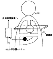
また、他の呼吸による体動アーチファクト抑制方法として、位相エンコード順を制御する方法がある(Respiratory Ordered Phase Encoding(ROPE):A Method for Reducing Respiratory Motion Artifacts in MR Imaging, Journal of Computer Assisted Tomography 9(4);835-838 1985, D. R. Bailes et al など)。この方法は、例えば図8に示すように、被検体80に取り付けた呼吸センサー82によって腹壁や胸壁の呼吸変動をモニターし、変位に対応して位相エンコード順を制御することにより、呼吸動によって生じる位相エンコード方向のアーチファクトを抑制する。呼吸時相と位相エンコードの対応を適当に選択することによって、撮像時間の延長をあまりせずに、体動アーチファクトを低減できる。
【0006】
一方、外部呼吸センサーを使わずに体動アーチファクトを減らす方法も提案されている(特開2000−296120号公報)。この方法では、ナビゲーションエコーを用いて呼吸動をモニターし、位相エンコードを制御する。即ち、図9に示すように撮像断面91を励起してエコー信号を計測する際に、画像形成用のエコー信号とは別にナビゲーションエコーを取得する。
【0007】
この方法に用いるパルスシーケンスを図10に示す。図示するように、まず、繰り返し時間1001の先頭でRFパルス1011を印加し、同時にスライス選択傾斜磁場1021を印加する。次に、位相エンコード傾斜磁場1031を印加した後、一連の反転するリードアウト傾斜磁場1071によって複数の本計測エコー1081を発生させ取得する。本計測エコー取得後、ナビゲーションエコー用傾斜磁場1051を印加し、ナビゲーションエコー1091を発生させ取得する。取得したナビゲーションエコー1091を1次元フーリエ変換し、被検体の投影像を作成する(1100)。この投影像を基準ナビゲーションエコーの投影像と比較することにより被検体の変位を算出し(1101)、予め作成しておいた変位と位相エンコードの対応表を参照し、今の変位に対応した位相エンコード量を決定する(1102)。ステップ1102で決定した位相エンコード量を次の繰り返し時間1002内における位相エンコード傾斜磁場1032を印加する際に用いる(1103)。この際、そのエンコード量での本計測データが既に取得済みであれば、次に近い位相エンコード量が1103で選択される。これによって体動アーチファクトが低減された画像が得られる(図9)。
【0008】
【発明が解決しようとする課題】
上述の方法は、図9に示すように、本計測の撮像断面91の面方向が呼吸動により被検体が動く方向と一致しているときには、最も安定な補正が可能となる。つまり、本計測撮像面内の呼吸変動を検出し、位相エンコード量を制御することは安定に実現可能であるが、撮像面に垂直方向に大きく呼吸動がある場合などは、ナビゲーションエコーによっては呼吸動をモニターできないこともあり、制御が正確に行えない場合もある。
【0009】
そこで本発明は、撮像断面と体動方向との関係に拘わらず、常にナビゲーションエコーを用いた位相エンコード制御を実現することができ、体動アーチファクトの抑制されたMR画像を得ることを目的とする。
【0010】
【課題を解決するための手段】
上記目的を達成するために、本発明のMRI装置では、体動をモニターすべき領域を撮像対象とする断面から独立して選択し、その領域から得たナビゲーションエコーを用いて算出した被検体の変位と、予め設定された変位と位相エンコードとの対応表に基き、続いて実行される本計測シーケンスにおける位相エンコードを制御する。
【0011】
即ち、本発明のMRI装置は、被検体に高周波磁場及び傾斜磁場をそれぞれ印加する磁場発生手段と、前記被検体からのNMR信号を検出する検出手段と、前記高周波磁場及び傾斜磁場の印加並びにNMR信号検出を所定のシーケンスに則り制御する制御手段と、検出したNMR信号を用いて前記被検体の断面像を再構成する演算手段とを備えたMRI装置において、
前記制御手段は、前記被検体の断面像を得るためのNMR信号を発生させる本計測シーケンスと、前記被検体の一部の領域からナビゲーションエコーを計測するナビゲーションシーケンスとを備え、前記ナビゲーションエコーから前記領域の変位を算出するとともに、算出された変位及び予め設定された変位と位相エンコードとの対応表に基き、前記ナビゲーションシーケンス後に実行される本計測シーケンスにおける位相エンコードを制御することを特徴とする。
好適には、前記ナビゲーションシーケンスで計測する領域は、前記本計測シーケンスで選択された断面とは異なる領域である。
【0012】
本発明のMRI装置によれば、変位と位相エンコードとの対応表に基いて本計測時の位相エンコードを制御するので、制御が容易となる。また被検体の変位を算出するためのナビゲーションエコーを検出する領域を、計測しようとする撮像断面とは独立して選択することにより、着目する被検体の体動を最も反映する領域からの信号を得ることができ、本計測撮像断面内の変位のみでなく、任意の方向の体動の変位量を検出して適切に位相エンコード量の制御を行うことが可能である。
【0013】
また本発明のMRI装置は、NMR信号を検出する検出手段として、本計測シーケンスで発生するエコー信号を検出する第1の検出手段と、ナビゲーションエコーを検出する第2の検出手段とを備えたことを特徴とする。
このような構成を備えた本発明のMRI装置によれば、画像化しようとする領域と、被検体の体動をモニターしようとする領域とが離れた場所であっても、ナビゲーションエコーを高感度で取得することができ、正確に被検体の変位をモニターし、体動アーチファクトを軽減することができる。
【0014】
【発明の実施の形態】
以下、本発明の実施の形態を説明する。
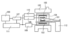
図1は、本発明が適用される典型的なMRI装置の構成を示す図である。このMRI装置は、被検体101が置かれる撮像空間に静磁場を発生する磁石102と、この空間に傾斜磁場を発生する傾斜磁場コイル103と、被検体101の撮像すべき領域に高周波磁場を発生するRFコイル104と、被検体101が発生するMR信号を検出するRFプローブ105と、被検体101を寝かせて撮像空間に搬入するためのベッド112が備えられている。さらに撮像空間から離れた位置に、これら傾斜磁場コイル103及びRFコイル104の駆動系109、110、RFプローブ105からの信号を処理する信号処理系106〜108及び制御部111が備えられている。
【0015】
傾斜磁場コイル103は、X、Y、Zの3方向の傾斜磁場コイルで構成され、傾斜磁場電源109からの信号に応じてそれぞれ傾斜磁場を発生する。この傾斜磁場の加え方により、被検体101の撮像すべき領域を選択することができ、また被検体101から発生するエコー信号に位置情報(位相エンコード)を付与することができる。
【0016】
RFコイル104はRF送信部110の信号に応じて高周波磁場を発生する。RFプローブ105の信号は、信号検出部106で検出され、信号処理部107で信号処理され、また計算により画像信号に変換される。画像は表示部108で表示される。
制御部111は、傾斜磁場電源109、RF送信部110、信号検出部106を、パルスシーケンスと呼ばれる制御のタイムチャートに則り制御し、所定のタイミングでRFパルスの照射、傾斜磁場の印加及びエコー信号の検出が行なわれるようにする。撮像方法によって種々の撮像シーケンスがあり、これら撮像シーケンスは制御部111のメモリ内に格納されている。本発明のMRI装置は、後に詳述するが、被検体の体動をモニターするためのナビゲーションエコーを計測するシーケンス(ナビゲーションシーケンス)を含む撮像シーケンスを備えている。
【0017】
制御部111は、この撮像シーケンスで得られるナビゲーションエコーを用いて被検体101の変位量を算出するとともに、変位量に基きナビゲーションシーケンスと組み合わされた本計測シーケンスにおける位相エンコードを制御する。この制御のために、制御部111のメモリ内には、被検体の変位量と位相エンコードの対応を予め設定した対応表が格納されている。対応表の求め方については後述する。
【0018】
以下、上記構成におけるMRI装置を用いた撮像方法の一実施形態を説明する。図2は、本実施形態で実行される撮像シーケンスの一例を示す図である。この実施形態では、本計測に先行してナビゲーションシーケンス2011を実行し、取得されたナビゲーションエコーから本計測シーケンス2121の位相エンコード量を決定する。また本計測シーケンス2121としてマルチショットEPIを採用した場合を説明する。但し、撮像シーケンスはマルチショットEPIに限らず種々の撮像シーケンスが採用可能である。
【0019】
ナビゲーションシーケンス2011は、本実施形態ではスピンエコー型のシーケンスで、90°パルス2021、180°パルス2031を印加して被検体を励起する。90°パルス及び180°パルスを印加する際に、スライス選択傾斜磁場2091、2071をそれぞれ印加し、モニターしようとする被検体の部位を局所的に選択する。ここでは、スライス選択傾斜磁場2091、2071は直交する2軸に印加し、励起パルスによる励起面を直交させて、モニターしたい部位を選択している。位相エンコードは行わない。リードアウト傾斜磁場2041、2051を印加することによって、励起した部位からナビゲーションエコー2111を取得する。その後、スピンを励起前の状態に戻すために傾斜磁場2061、2081、2101を印加する。こうして取得したナビゲーションエコー2111は、被検体の変位を算出するために用いられる。
【0020】
本計測シーケンス2121では、励起パルス2131と共にスライス選択傾斜磁場2141を印加し、位相エンコードのオフセット2151を与えた後、リードアウト傾斜磁場2191の反転を繰り返すと共に、位相エンコード傾斜磁場2161をブリップ状に印加して位相エンコードされた複数のエコー信号2201を被検体101の選択された領域から取得する。
【0021】
このようにナビゲーションシーケンス2011と本計測シーケンス2121はRFパルスによる励起からデータ取得までそれぞれ独立して実行されるので、撮像位置も各々任意に選択できる。
【0022】
上述したナビゲーションシーケンス2011と本計測シーケンス2121とを繰り返し、1枚の画像に必要な数のエコー信号2201を計測する。この際、本計測シーケンス2121の繰り返しにおいて印加される傾斜磁場のオフセット2151は、直前のナビゲーションエコーからの算出された被検体の変位に基き制御される。
【0023】
次にナビゲーションエコーを用いた位相エンコード量の制御について説明する。
【0024】
まず制御部111は、取得されたナビゲーションエコー2111を1次元フーリエ変換し、被検体の投影像を作成する(ステップ200)。この投影像から着目部位の変位を求める(ステップ201)。変位の検出方法は、例えば、前述の特開2000-296120号公報に記載されるように、基準エコーを設定し、その投影像と比較しても良いし、ナビゲーションエコー2111の投影像自身の信号強度プロファイルからエッジを検出する手法など用いても良い。変位が求められたならば、制御部111のメモリに記憶された変位と位相エンコード量の対応表に基き、算出された変位に対応した位相エンコード量を決定する(ステップ202)。
【0025】
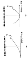
変位と位相エンコード量の対応表は、次のように作成することができる。まず、図3に示すように連続する複数回のナビゲーションシーケンス301を実行し、複数個のナビゲーションエコー302を時系列的に取得する。これら複数個のナビゲーションエコー302から、それらを取得したときの、被検体の変位を求める。問題とする被検体の体動は、呼吸動のような周期的な動きであり、得られた変位を時系列にプロットすると、図4(a)に示すように、周期的な体動の一周期401が得られる。この体動の一周期の間に全ての位相エンコードが網羅されるように、変位と位相エンコード量の対応表402(同図(b))を決定する。図示する例では、動きの変化が最も少なくなる変位の最大及び最小の付近に、位相エンコード0(低周波領域)付近を割り当て、動きの大きいところに位相エンコードの高周波領域を割り当てるようにしている。また図示する例では、単純な線形対応の例を示しているが、対応関係はこの限りではない。
【0026】
次に制御部111は、このような対応表を用いて位相エンコード量を決定した後、この決定した位相エンコード量を用いて、次いで実行する本計測シーケンスの位相エンコード量、即ち、位相エンコード方向の傾斜磁場2151を設定する(ステップ203)。この際、設定した位相エンコード量での本計測データが既に取得されていた場合には、設定した位相エンコード量に至近であって、本計測データが未取得である位相エンコード量を設定する。
【0027】
こうして設定された位相エンコード2151で、本計測シーケンス2121を終了した後、次のナビゲーションシーケンス2012が実行され、続く本計測シーケンスの位相エンコード量が同様に決定される。以下、画像再構成に必要な全エコーが取得されるまで、ナビゲーションシーケンスと本計測シーケンスが交互に繰り返される。
【0028】
このように本実施形態では、ナビゲーションシーケンス2011を、本計測シーケンス2121から独立して実行するようにしたので、本計測における撮像領域と関わりなく、最も体動モニターすべき部位からの信号を得ることができ、常に体動アーチファクトを抑制することができる。
【0029】
本実施形態の具体的な使用例を図5に示す。図5は、横隔膜の呼吸動をナビゲーションエコーでモニターながら心臓撮像を行う場合を示している。図5(a)に示すように、心臓501に対し、体軸方向(図中x方向)と直交する断面506を撮像する場合、心臓の呼吸動は撮像面内より撮像面に垂直な体軸方向が大きい。このような場合、ナビゲーションエコーを取得する位置と本計測撮像断面が同じであると、最も呼吸動の大きなx方向への変位をモニターできない。
【0030】
そこで、肺502と肝504の境界部分にあって、体軸方向の呼吸動を最も反映する横隔膜503からナビゲーションエコーを得ることとし、x方向の変位をモニターする。このため、図2のナビゲーションシーケンス2012において90°RFパルス2021で横隔膜503を含む面507(図5(b))を励起し、180°RFパルス2031で横隔膜503を含み且つ面507と直交する面508を励起し、横隔膜503を垂直に横切る領域505からナビゲーションエコーを得る。
【0031】
取得したナビゲーションエコーのローデータをx方向に1次元フーリエ変換した後、絶対値化する。ナビゲーションエコーは位相エンコードを印加していないので絶対値化されたエコーは励起部位の投影像となっている。この投影像の信号強度プロファイルより呼吸動する横隔膜のx方向の変位を検知することができる。こうして求めた変位から、予め設定された変位−位相エンコード量対応表に基づいた位相エンコード量を求め、心臓撮像用の本計測シーケンスで印加する。
【0032】
なお、ナビゲーションエコーは、図示する例に限らず、図中点線51で示すように横隔膜に対し傾きのある領域から取得するようにしても良い。また横隔膜に限らず、図中点線52に示すように、心臓の境界など他の部位から取得するようにしても良い。
【0033】
次に本発明の別の実施形態として、MR信号を検出するRFプローブ105及び信号処理系を2系統備えたMRI装置を説明する。このMRI装置の受信系の構成を図6に示す。その他の構成は図1のMRI装置と同様であるので省略する。
【0034】
図示するように、このMRI装置は本計測用のRFプローブ601と、ナビゲーションエコー用のRFプローブ604の2つのRFプローブを備え、それに対応する2系統の信号検出部と信号処理部を備えている。この実施形態は、ナビゲーションエコー取得位置603と撮像部位602が離れている場合に好適であり、例えば、図示するように、ナビゲーションエコーでの呼吸モニターを横隔膜の動きで行い、頭部の拡散画像を呼吸同期下で行うことが可能である。
【0035】
撮像シーケンスとしては、図2と同様のナビゲーションシーケンスと本計測シーケンスとを組み合わせたシーケンスを実行する。ナビゲーションシーケンスの実行毎にナビゲーションエコー用のRFプローブ604が検出したエコーに対し、RFプローブ604が接続された信号処理部で、1次元フーリエ変換を施すとともに、モニター部位の変位を算出し、この変位に対応する位相エンコード量を決定する。この位相エンコード量で次の本計測を行い、本計測用のRFプローブ601で検出した信号を収集して、最終的に1枚の画像用のデータを得る。これを2次元フーリエ変換し、画像信号に変換し、表示部に表示する。
【0036】
本実施形態によれば、撮像部位の位置や断面方向に関係なく、体動モニターすべき部位に最適なRFプローブを用いてナビゲーションエコーを取得できるので、精度のよい体動モニターを行なうことができ、結果として体動アーチファクトを効果的に抑制することができる。
【0037】
尚、以上説明した実施形態では、本計測シーケンスとしてマルチショットEPI法によるシーケンスを例示したが、本発明はスピンエコー法、高速スピンエコー法、グラディエントエコー法、3次元-EPI法など、位相エンコードループを有する種々のパルスシーケンスに適用することができる。
【0038】
また変位と位相エンコード量の対応表として、変位の最大及び最小の付近に、位相エンコード0(低周波領域)付近を割り当てた例を示したが、対応表は種々の変更が可能であり、最も体動アーチファクトが少なくなるように選択される。例えば図7(a)に示すように、変位に対し位相エンコード量を単調に変化させたり、図7(b)に示すように、最小変位を零エンコードに割り当てたりすることも可能である。
【0039】
【発明の効果】
本発明は、本計測シーケンスとは独立したナビゲーションシーケンスにおいて取得されたナビゲーションエコーから着目部位の呼吸動をモニターするため、本計測撮像断面に直交する変位でも、すなわち、任意の方向に体動の変位量検出して位相エンコード量の制御を行うことが可能である。
【図面の簡単な説明】
【図1】本発明が適用されるMRI装置の概要を示す図。
【図2】本発明のMRI装置が実行する撮像シーケンスの一例を示す図。
【図3】変位と位相エンコード量の対応を求める方法を説明する図。
【図4】変位の周期と位相エンコード量の対応を示す模式図。
【図5】図2の撮像シーケンスの適用例を説明する図。
【図6】本発明のMRI装置の他の実施形態を示す図。
【図7】変位と位相エンコード量の対応例を示す模式図。
【図8】従来の体動アーチファクト抑制方法を説明する図。
【図9】従来の体動アーチファクト抑制方法を説明する図。
【図10】図9の体動アーチファクト抑制方法で用いるパルスシーケンスを示す図。
【符号の説明】
101・・・被検体、102・・・静磁場磁石、103・・・傾斜磁場コイル、104・・・RFコイル、105・・・RFプローブ、106・・・信号検出部、107・・・信号処理部、108・・・表示部、109・・・傾斜磁場電源、110・・・RF送信部、111・・・制御部[0001]
BACKGROUND OF THE INVENTION
The present invention relates to a magnetic resonance imaging (MRI) apparatus that measures nuclear magnetic resonance (hereinafter referred to as “NMR”) signals from hydrogen, phosphorus, etc. in a subject and visualizes nuclear density distribution, relaxation time distribution, etc. In particular, the present invention relates to an MRI apparatus that realizes reduction of artifacts due to body movement.
[0002]
[Prior art]
In an MRI apparatus, an object placed in a static magnetic field is irradiated with an RF pulse to excite atomic nuclei constituting the tissue of the object, thereby detecting the NMR signal generated from the object as an echo signal, A desired tomographic image of the subject is reconstructed by signal processing. At this time, in order to give position information to the echo signal, different phase encoding is given depending on the gradient magnetic field. Values such as 128, 256, and 512 are usually adopted as the number of phase encodings necessary for reconstructing one MR image. In MRI, a phase-encoded echo signal is two-dimensionally Fourier transformed to reconstruct one image.
[0003]
By the way, it is known that if the subject moves while acquiring echo signals for one MR image, a large artifact is generated in the image. This is called body movement artifact. The body motion artifact occurs because a predetermined phase encoding amount is to be given to a predetermined measurement point, but an image is created by performing Fourier transform in a state where the phase encoding amount is applied to another measurement point by movement. A typical example of a body motion artifact is a body motion artifact due to breathing.
[0004]
As a method of removing body motion artifacts due to respiration, there is a synchronous imaging method that matches the time phase of respiration. In this method, respiratory motion is monitored by a respiration sensor attached to a subject, and an imaging trigger is set at a specific time phase to collect data. Thereby, only the data of the specific displacement in respiratory motion is collected, and the image in which the body motion artifact is reduced is acquired. However, since this method does not acquire data until the trigger is detected, the data collection efficiency is low and the imaging time is extended.
[0005]
Another method for suppressing body motion artifacts due to breathing is to control the phase encoding order (Respiratory Ordered Phase Encoding (ROPE): A Method for Reducing Respiratory Motion Artifacts in MR Imaging, Journal of Computer Assisted Tomography 9 (4 ); 835-838 1985, DR Bailes et al). For example, as shown in FIG. 8, this method is caused by respiratory motion by monitoring the respiratory fluctuation of the abdominal wall or the chest wall with a respiratory sensor 82 attached to the
[0006]
On the other hand, a method for reducing body motion artifacts without using an external respiratory sensor has also been proposed (Japanese Patent Laid-Open No. 2000-296120). In this method, navigation echoes are used to monitor respiratory motion and control phase encoding. That is, as shown in FIG. 9, when the imaging section 91 is excited and the echo signal is measured, the navigation echo is acquired separately from the echo signal for image formation.
[0007]
A pulse sequence used in this method is shown in FIG. As shown in the figure, first, an
[0008]
[Problems to be solved by the invention]
As shown in FIG. 9, the above-described method enables the most stable correction when the surface direction of the imaging section 91 of the main measurement coincides with the direction in which the subject moves due to respiratory motion. In other words, it is possible to stably detect respiratory fluctuations in this measurement imaging plane and control the phase encoding amount, but depending on the navigation echo, if there is a large amount of respiratory movement perpendicular to the imaging plane, The movement may not be monitored, and the control may not be performed accurately.
[0009]
Therefore, an object of the present invention is to obtain MR images in which phase encoding control using navigation echo can always be realized regardless of the relationship between the imaging section and the body motion direction, and body motion artifacts are suppressed. .
[0010]
[Means for Solving the Problems]
In order to achieve the above object, in the MRI apparatus of the present invention, an area to be monitored for body motion is selected independently from the cross section to be imaged, and the object calculated using the navigation echo obtained from the area is selected. Based on the correspondence table of the displacement and the preset displacement and phase encoding, the phase encoding in the subsequent measurement sequence to be executed is controlled.
[0011]
That is, the MRI apparatus of the present invention includes a magnetic field generating unit that applies a high-frequency magnetic field and a gradient magnetic field to a subject, a detection unit that detects an NMR signal from the subject, the application of the high-frequency magnetic field and the gradient magnetic field, and an NMR In an MRI apparatus comprising control means for controlling signal detection according to a predetermined sequence, and arithmetic means for reconstructing a cross-sectional image of the subject using the detected NMR signal,
The control means includes a main measurement sequence for generating an NMR signal for obtaining a cross-sectional image of the subject , and a navigation sequence for measuring a navigation echo from a partial region of the subject. The displacement of the region is calculated, and the phase encoding in the main measurement sequence executed after the navigation sequence is controlled based on the calculated displacement and the correspondence table between the preset displacement and the phase encoding.
Preferably, the area measured in the navigation sequence is an area different from the cross section selected in the main measurement sequence.
[0012]
According to the MRI apparatus of the present invention, the phase encoding at the time of the main measurement is controlled based on the correspondence table between the displacement and the phase encoding, so that the control becomes easy. In addition, by selecting the area for detecting the navigation echo for calculating the displacement of the subject independently of the imaging cross section to be measured, a signal from the area most reflecting the body movement of the subject of interest is obtained. It is possible to appropriately control the phase encoding amount by detecting not only the displacement in the measurement imaging section but also the displacement amount of the body movement in an arbitrary direction.
[0013]
In addition, the MRI apparatus of the present invention includes first detection means for detecting an echo signal generated in this measurement sequence and second detection means for detecting a navigation echo as detection means for detecting an NMR signal. It is characterized by.
According to the MRI apparatus of the present invention having such a configuration, the navigation echo is highly sensitive even when the region to be imaged is separated from the region to be monitored for the body movement of the subject. The displacement of the subject can be accurately monitored and the body motion artifact can be reduced.
[0014]
DETAILED DESCRIPTION OF THE INVENTION
Embodiments of the present invention will be described below.
FIG. 1 is a diagram showing a configuration of a typical MRI apparatus to which the present invention is applied. This MRI apparatus generates a high-frequency magnetic field in a region to be imaged of the subject 101, a
[0015]
The gradient
[0016]
The
The
[0017]
The
[0018]
Hereinafter, an embodiment of an imaging method using the MRI apparatus having the above configuration will be described. FIG. 2 is a diagram illustrating an example of an imaging sequence executed in the present embodiment. In this embodiment, the
[0019]
The
[0020]
In this
[0021]
As described above, since the
[0022]
The above-described
[0023]
Next, control of the phase encoding amount using navigation echo will be described.
[0024]
First, the
[0025]
The correspondence table between the displacement and the phase encoding amount can be created as follows. First, as shown in FIG. 3, a plurality of
[0026]
Next, after determining the phase encoding amount using such a correspondence table, the
[0027]
After completing the
[0028]
As described above, in the present embodiment, the
[0029]
A specific example of use of this embodiment is shown in FIG. FIG. 5 shows a case where cardiac imaging is performed while monitoring the respiratory motion of the diaphragm using navigation echoes. As shown in FIG. 5A, when imaging a
[0030]
Therefore, the navigation echo is obtained from the
[0031]
The obtained raw data of navigation echoes are converted into absolute values after one-dimensional Fourier transform in the x direction. Since the navigation echo does not apply phase encoding, the echo converted into an absolute value is a projected image of the excitation site. From the signal intensity profile of the projection image, the displacement of the diaphragm moving in the x direction in the respiratory motion can be detected. From the displacement thus obtained, a phase encoding amount based on a preset displacement-phase encoding amount correspondence table is obtained and applied in the main measurement sequence for cardiac imaging.
[0032]
The navigation echo is not limited to the illustrated example, and may be acquired from a region inclined with respect to the diaphragm as indicated by a dotted
[0033]
Next, as another embodiment of the present invention, an MRI apparatus including two systems of an
[0034]
As shown in the figure, this MRI apparatus includes two RF probes, that is, an
[0035]
As the imaging sequence, a sequence in which a navigation sequence similar to FIG. 2 and the main measurement sequence are combined is executed. The echo detected by the navigation
[0036]
According to the present embodiment, navigation echoes can be acquired using an RF probe that is optimal for the part to be monitored regardless of the position of the imaging part and the cross-sectional direction, so that accurate body movement monitoring can be performed. As a result, the body motion artifact can be effectively suppressed.
[0037]
In the embodiment described above, a sequence by the multi-shot EPI method is exemplified as the main measurement sequence. However, the present invention is a phase encoding loop such as a spin echo method, a fast spin echo method, a gradient echo method, and a three-dimensional EPI method. It can be applied to various pulse sequences having
[0038]
In addition, as an example of the correspondence table between displacement and phase encoding amount, an example in which the vicinity of phase encoding 0 (low frequency region) is assigned near the maximum and minimum of displacement is shown, but the correspondence table can be changed in various ways. Selected to reduce body motion artifacts. For example, as shown in FIG. 7A, the phase encoding amount can be changed monotonously with respect to the displacement, or the minimum displacement can be assigned to zero encoding as shown in FIG. 7B.
[0039]
【The invention's effect】
Since the present invention monitors the respiratory motion of the region of interest from the navigation echo acquired in the navigation sequence independent of the main measurement sequence, even with a displacement orthogonal to the main measurement imaging section, that is, the displacement of the body motion in an arbitrary direction It is possible to control the amount of phase encoding by detecting the amount.
[Brief description of the drawings]
FIG. 1 is a diagram showing an outline of an MRI apparatus to which the present invention is applied.
FIG. 2 is a diagram showing an example of an imaging sequence executed by the MRI apparatus of the present invention.
FIG. 3 is a diagram for explaining a method for obtaining correspondence between displacement and phase encoding amount;
FIG. 4 is a schematic diagram showing a correspondence between a displacement period and a phase encoding amount.
FIG. 5 is a diagram for explaining an application example of the imaging sequence of FIG. 2;
FIG. 6 is a view showing another embodiment of the MRI apparatus of the present invention.
FIG. 7 is a schematic diagram showing a correspondence example between a displacement and a phase encoding amount.
FIG. 8 is a diagram for explaining a conventional method for suppressing body motion artifacts.
FIG. 9 is a diagram for explaining a conventional method for suppressing body motion artifacts.
10 is a diagram showing a pulse sequence used in the body motion artifact suppression method of FIG. 9. FIG.
[Explanation of symbols]
101 ... subject, 102 ... static magnetic field magnet, 103 ... gradient coil, 104 ... RF coil, 105 ... RF probe, 106 ... signal detector, 107 ... signal
Claims (2)
前記制御手段は、前記被検体の断面像を得るためのNMR信号を発生させる本計測シーケンスと、前記本計測シーケンスで選択された断面から独立して選択された領域からナビゲーションエコーを計測するナビゲーションシーケンスとを備え、
前記検出手段は、前記本計測シーケンスにおけるエコー信号を検出する第1の検出手段及び前記ナビゲーションエコーを検出する第2の検出手段を備え、
前記制御手段は、前記ナビゲーションエコーから前記領域の変位を算出するとともに、算出された変位及び予め設定された変位と位相エンコードとの対応表に基き、前記ナビゲーションシーケンス後に実行される本計測シーケンスにおける位相エンコードを制御することを特徴とする磁気共鳴イメージング装置。Magnetic field generation means for applying a high-frequency magnetic field and a gradient magnetic field to the subject, detection means for detecting an NMR signal from the subject, and application of the high-frequency magnetic field and the gradient magnetic field and NMR signal detection are controlled in accordance with a predetermined sequence. In an MRI apparatus comprising control means for performing, and arithmetic means for reconstructing a cross-sectional image of the subject using the detected NMR signal,
The control means includes a main measurement sequence for generating an NMR signal for obtaining a cross-sectional image of the subject, and a navigation sequence for measuring a navigation echo from a region selected independently from the cross section selected in the main measurement sequence. And
The detection means includes first detection means for detecting an echo signal in the main measurement sequence and second detection means for detecting the navigation echo,
The control means calculates the displacement of the region from the navigation echo, and based on the calculated displacement and a correspondence table of a preset displacement and phase encoding, the phase in the main measurement sequence executed after the navigation sequence A magnetic resonance imaging apparatus characterized by controlling encoding.
前記ナビゲーションシーケンスで計測する領域は、前記本計測シーケンスで選択された断面とは異なる領域であることを特徴とする磁気共鳴イメージング装置。The magnetic resonance imaging apparatus according to claim 1,
An area to be measured in the navigation sequence is an area different from a cross section selected in the main measurement sequence.
Priority Applications (1)
| Application Number | Priority Date | Filing Date | Title |
|---|---|---|---|
| JP2002187645A JP3967210B2 (en) | 2002-06-27 | 2002-06-27 | Magnetic resonance imaging system |
Applications Claiming Priority (1)
| Application Number | Priority Date | Filing Date | Title |
|---|---|---|---|
| JP2002187645A JP3967210B2 (en) | 2002-06-27 | 2002-06-27 | Magnetic resonance imaging system |
Publications (3)
| Publication Number | Publication Date |
|---|---|
| JP2004024669A JP2004024669A (en) | 2004-01-29 |
| JP2004024669A5 JP2004024669A5 (en) | 2005-10-13 |
| JP3967210B2 true JP3967210B2 (en) | 2007-08-29 |
Family
ID=31182617
Family Applications (1)
| Application Number | Title | Priority Date | Filing Date |
|---|---|---|---|
| JP2002187645A Expired - Fee Related JP3967210B2 (en) | 2002-06-27 | 2002-06-27 | Magnetic resonance imaging system |
Country Status (1)
| Country | Link |
|---|---|
| JP (1) | JP3967210B2 (en) |
Cited By (2)
| Publication number | Priority date | Publication date | Assignee | Title |
|---|---|---|---|---|
| CN109709958A (en) * | 2018-12-26 | 2019-05-03 | 南京航空航天大学 | A kind of extension control method for AGV electromagnetic navigation control system |
| CN109917315A (en) * | 2019-04-30 | 2019-06-21 | 上海联影医疗科技有限公司 | MRI scan method, apparatus, computer equipment and storage medium |
Families Citing this family (10)
| Publication number | Priority date | Publication date | Assignee | Title |
|---|---|---|---|---|
| JPWO2005102162A1 (en) * | 2004-04-27 | 2008-03-06 | 株式会社日立メディコ | Magnetic resonance imaging apparatus and method |
| JP4558397B2 (en) * | 2004-07-15 | 2010-10-06 | 株式会社日立メディコ | Magnetic resonance imaging system |
| JP4711732B2 (en) * | 2005-05-12 | 2011-06-29 | 株式会社日立メディコ | Magnetic resonance imaging device |
| JP5064721B2 (en) * | 2006-05-15 | 2012-10-31 | 株式会社日立メディコ | Magnetic resonance imaging system |
| JP2008154887A (en) * | 2006-12-26 | 2008-07-10 | Ge Medical Systems Global Technology Co Llc | Mri apparatus |
| JP2009106573A (en) * | 2007-10-31 | 2009-05-21 | Ge Medical Systems Global Technology Co Llc | Magnetic resonance imaging apparatus |
| JP5388749B2 (en) * | 2009-08-11 | 2014-01-15 | 株式会社東芝 | Magnetic resonance imaging system |
| CN104717920B (en) * | 2012-11-22 | 2018-04-27 | 东芝医疗系统株式会社 | MR imaging apparatus and MR imaging method |
| JP5977158B2 (en) | 2012-11-30 | 2016-08-24 | ジーイー・メディカル・システムズ・グローバル・テクノロジー・カンパニー・エルエルシー | Detection apparatus, magnetic resonance apparatus, detection method, and program |
| JP2021183031A (en) * | 2020-05-21 | 2021-12-02 | 株式会社日立製作所 | Magnetic resonance imaging apparatus |
-
2002
- 2002-06-27 JP JP2002187645A patent/JP3967210B2/en not_active Expired - Fee Related
Cited By (5)
| Publication number | Priority date | Publication date | Assignee | Title |
|---|---|---|---|---|
| CN109709958A (en) * | 2018-12-26 | 2019-05-03 | 南京航空航天大学 | A kind of extension control method for AGV electromagnetic navigation control system |
| CN109709958B (en) * | 2018-12-26 | 2020-10-27 | 南京航空航天大学 | Extensible control method for AGV electromagnetic navigation control system |
| CN109917315A (en) * | 2019-04-30 | 2019-06-21 | 上海联影医疗科技有限公司 | MRI scan method, apparatus, computer equipment and storage medium |
| CN109917315B (en) * | 2019-04-30 | 2021-09-28 | 上海联影医疗科技股份有限公司 | Magnetic resonance imaging scanning method, magnetic resonance imaging scanning device, computer equipment and storage medium |
| US11774534B2 (en) | 2019-04-30 | 2023-10-03 | Shanghai United Imaging Healthcare Co., Ltd. | Systems and methods for magnetic resonance imaging |
Also Published As
| Publication number | Publication date |
|---|---|
| JP2004024669A (en) | 2004-01-29 |
Similar Documents
| Publication | Publication Date | Title |
|---|---|---|
| US9301704B2 (en) | Magnetic resonance imaging system for non-contrast MRA and magnetic resonance signal acquisition method employed by the same | |
| US7358732B2 (en) | System, method, software arrangement and computer-accessible medium for providing real-time motion correction by utilizing clover leaf navigators | |
| JP4820567B2 (en) | Magnetic resonance imaging apparatus and magnetic resonance signal collection method | |
| US20090010514A1 (en) | Magnetic Resonance Imaging Device, Image Data Correcting Device and Image Data Correcting Method | |
| JP5074211B2 (en) | Magnetic resonance imaging system | |
| JP6008839B2 (en) | Magnetic resonance imaging apparatus and magnetic resonance imaging method | |
| JP3967210B2 (en) | Magnetic resonance imaging system | |
| JP5536665B2 (en) | Magnetic resonance imaging apparatus and magnetic resonance imaging method | |
| US8909321B2 (en) | Diagnostic imaging apparatus, magnetic resonance imaging apparatus, and X-ray CT apparatus | |
| US7616981B2 (en) | Inspection apparatus using nuclear magnetic resonance | |
| JP5372015B2 (en) | Magnetic resonance imaging apparatus and synchronous imaging method | |
| JP4250251B2 (en) | Magnetic resonance imaging system | |
| JP4060459B2 (en) | Magnetic resonance imaging system | |
| JP2005040416A (en) | Magnetic resonance imaging apparatus | |
| JP2003260037A (en) | Device for acquiring magnetic resonance signal and magnetic resonance photographing apparatus | |
| JP2008055023A (en) | Magnetic resonance imaging apparatus | |
| JP4349647B2 (en) | Magnetic resonance imaging system | |
| JPH10201736A (en) | Examination system with magnetic resonance | |
| JP5371620B2 (en) | Nuclear magnetic resonance imaging system | |
| JP5421600B2 (en) | Nuclear magnetic resonance imaging apparatus and method of operating nuclear magnetic resonance imaging apparatus | |
| JP2005021488A (en) | Magnetic resonance imaging equipment | |
| JP4454268B2 (en) | Magnetic resonance imaging system | |
| JP2004041476A (en) | Magnetic resonance imaging apparatus |
Legal Events
| Date | Code | Title | Description |
|---|---|---|---|
| A521 | Written amendment |
Free format text: JAPANESE INTERMEDIATE CODE: A523 Effective date: 20050601 |
|
| A621 | Written request for application examination |
Free format text: JAPANESE INTERMEDIATE CODE: A621 Effective date: 20050601 |
|
| A977 | Report on retrieval |
Free format text: JAPANESE INTERMEDIATE CODE: A971007 Effective date: 20070220 |
|
| A131 | Notification of reasons for refusal |
Free format text: JAPANESE INTERMEDIATE CODE: A131 Effective date: 20070306 |
|
| A521 | Written amendment |
Free format text: JAPANESE INTERMEDIATE CODE: A523 Effective date: 20070425 |
|
| TRDD | Decision of grant or rejection written | ||
| A01 | Written decision to grant a patent or to grant a registration (utility model) |
Free format text: JAPANESE INTERMEDIATE CODE: A01 Effective date: 20070529 |
|
| A61 | First payment of annual fees (during grant procedure) |
Free format text: JAPANESE INTERMEDIATE CODE: A61 Effective date: 20070530 |
|
| R150 | Certificate of patent or registration of utility model |
Free format text: JAPANESE INTERMEDIATE CODE: R150 |
|
| FPAY | Renewal fee payment (event date is renewal date of database) |
Free format text: PAYMENT UNTIL: 20110608 Year of fee payment: 4 |
|
| FPAY | Renewal fee payment (event date is renewal date of database) |
Free format text: PAYMENT UNTIL: 20110608 Year of fee payment: 4 |
|
| FPAY | Renewal fee payment (event date is renewal date of database) |
Free format text: PAYMENT UNTIL: 20120608 Year of fee payment: 5 |
|
| FPAY | Renewal fee payment (event date is renewal date of database) |
Free format text: PAYMENT UNTIL: 20120608 Year of fee payment: 5 |
|
| FPAY | Renewal fee payment (event date is renewal date of database) |
Free format text: PAYMENT UNTIL: 20130608 Year of fee payment: 6 |
|
| LAPS | Cancellation because of no payment of annual fees |