JP3966866B2 - Imaging apparatus, camera, and signal processing method - Google Patents
Imaging apparatus, camera, and signal processing method Download PDFInfo
- Publication number
- JP3966866B2 JP3966866B2 JP2004117670A JP2004117670A JP3966866B2 JP 3966866 B2 JP3966866 B2 JP 3966866B2 JP 2004117670 A JP2004117670 A JP 2004117670A JP 2004117670 A JP2004117670 A JP 2004117670A JP 3966866 B2 JP3966866 B2 JP 3966866B2
- Authority
- JP
- Japan
- Prior art keywords
- color signal
- green
- red
- value
- color
- Prior art date
- Legal status (The legal status is an assumption and is not a legal conclusion. Google has not performed a legal analysis and makes no representation as to the accuracy of the status listed.)
- Expired - Fee Related
Links
Images
Landscapes
- Color Television Image Signal Generators (AREA)
- Processing Of Color Television Signals (AREA)
Description
この発明は、撮像装置に関し、特に赤外除去フィルタ(IRCF)を用いずに比視感度補正を行う信号処理手段を具備した撮像装置に関する。本発明はまた、そのような撮像装置を備えたカメラに関するものである。本発明はさらに、そのような撮像装置における信号処理方法に関する。 The present invention relates to an image pickup apparatus, and more particularly to an image pickup apparatus including a signal processing unit that performs relative visibility correction without using an infrared removal filter (IRCF). The present invention also relates to a camera provided with such an imaging apparatus. The present invention further relates to a signal processing method in such an imaging apparatus.
従来の撮像装置は、入射光を結像するレンズと、レンズにより結像した光学像を電気信号に変換する撮像素子と、撮像素子から得られた電気信号に対し信号処理を施すことにより所定の画像信号を得る信号処理手段とを有している。
通常撮像素子として用いるCCD(Charge Coupled Device)センサー又はCMOS(Complimentary Metal Oxide)センサを一枚だけで撮像装置を構成する場合、即ち、単板式のセンサーにおいては、色分解を行う色フィルタとして、画素ごとに異なる色のものがセンサー上に設けられている。
赤(R)、緑(G)、青(B)の色信号を得るには、R、G、Bに対応する光の帯域を透過させる、R、G、Bの原色フィルタを用いる場合と、マジェンタ(Mg)、シアン(Cy)、イエロー(Ye)、Gの補色フィルタを用いる場合がある。上記のいずれの色フィルタも染料もしくは顔料を用いて目的の色を透過させるようにその分光透過特性が設計されているが、近赤外領域でも一定の透過率を有する。また、撮像素子の光電変換部は主にシリコン(Si)などの半導体で構成されているため、光電変換部の分光感度特性は波長の長い近赤外光まで感度を有している。よって、色フィルタを具備した撮像素子から得られた信号は近赤外領域の光線にも反応している。
A conventional imaging device has a lens that forms incident light, an imaging device that converts an optical image formed by the lens into an electrical signal, and a signal process performed on the electrical signal obtained from the imaging device to obtain a predetermined signal. Signal processing means for obtaining an image signal.
When an image pickup apparatus is configured with only one CCD (Charge Coupled Device) sensor or CMOS (Complementary Metal Oxide) sensor used as a normal image sensor, that is, in a single-plate sensor, a pixel filter is used as a color filter for color separation. Different colors are provided on the sensors.
In order to obtain red (R), green (G), and blue (B) color signals, R, G, and B primary color filters that transmit light bands corresponding to R, G, and B are used. In some cases, magenta (Mg), cyan (Cy), yellow (Ye), and G complementary color filters are used. Each of the above color filters is designed to have a spectral transmission characteristic so as to transmit a target color using a dye or pigment, but has a certain transmittance even in the near infrared region. Further, since the photoelectric conversion unit of the image sensor is mainly composed of a semiconductor such as silicon (Si), the spectral sensitivity characteristic of the photoelectric conversion unit is sensitive to near infrared light having a long wavelength. Therefore, the signal obtained from the image sensor provided with the color filter also reacts to light in the near infrared region.
一方、人間の色に対する感度特性である色覚特性および明るさに対する感度特性である比視感度特性はその感度が可視域といわれる380nmから780nmまでの感度特性であり、700nmより長波長域ではほとんど感度を有さない。そこで、撮像装置の色再現性を人間の色覚特性に合わせるためには、撮像素子の前に近赤外領域の光線を通過させない視感度補正用の赤外線除去フィルタ(以後、IRCF:Infrared Cut Filter)を設ける必要があった。 On the other hand, the color vision characteristic, which is a sensitivity characteristic for human colors, and the relative visual sensitivity characteristic, which is a sensitivity characteristic for brightness, are sensitivity characteristics from 380 nm to 780 nm, which are referred to as the visible range, and are almost in the wavelength range longer than 700 nm. Does not have. Therefore, in order to match the color reproducibility of the image pickup device with human color vision characteristics, an infrared ray removal filter for correcting visibility (hereinafter referred to as IRCF: Infrared Cut Filter) that does not allow light in the near infrared region to pass in front of the image pickup device. It was necessary to provide.
一方、例えば監視カメラ等のように色再現性よりも感度を重視する場合には、近赤外領域の光を利用するため、IRCFを設けず撮像素子に近赤外光を受光させるほうが良い。 On the other hand, in the case where sensitivity is more important than color reproducibility, for example, in a surveillance camera, it is better to make the imaging device receive near infrared light without providing IRCF in order to use light in the near infrared region.
そこで、色再現性を必要とするときはIRCFを撮像素子の前に設置し、感度を優先するときは近赤外の光線を受光するために、IRCFを移動させる機構手段を設けたり、入射光量を調整する絞りの一部にIRCFを設け、光量に応じてIRCFを撮像素子の前に設置したり除去したりする技術が種々提案されている(例えば、特許文献1参照)。
また、IRCFを設置せずにホワイトバランスを取り、IRCFを設置したときに輝度信号を生成するR、G、B信号の混色比とは異なる混色比で輝度信号を生成することで感度向上を図る技術も提案されている(特許文献2、3参照)。
Therefore, when color reproducibility is required, an IRCF is installed in front of the image sensor, and when priority is given to sensitivity, a mechanism means for moving the IRCF is provided to receive near-infrared rays. Various techniques have been proposed in which an IRCF is provided in a part of a diaphragm for adjusting the amount of IR, and the IRCF is installed or removed in front of an image sensor in accordance with the amount of light (see, for example, Patent Document 1).
Further, white balance is taken without installing the IRCF, and sensitivity is improved by generating a luminance signal with a color mixture ratio different from the color mixture ratio of the R, G, and B signals that generate the luminance signal when the IRCF is installed. Technology has also been proposed (see
しかしながら、特許文献1に挙げた従来の撮像装置はIRCFを移動させる機構手段が必要であり、撮像素子を含むユニットの小型化に不利であり、撮像素子の電子シャッタを用いて光量調整を行う簡易的な撮像装置(例えば、ピーシーカメラ(PCカメラ)、携帯電話用カメラ、トイカメラ(TOYカメラ)、民生用監視カメラ)は絞り機構を有していないことが多いため、新たにIRCFを着脱する機構手段を設けなければならない。
However, the conventional imaging device described in
また、特許文献2及び3に挙げた撮像装置は白黒の映像信号を得るときは問題ないが、カラーの映像信号を得るときは、色信号はホワイトバランスを合わせるのみであり、さらに輝度信号も人間の比視感度特性が考慮されていない色信号比であるため、そのカラーの映像信号は人間の色覚特性又はそれを線形変換することにより得られる分光感度特性で得られるR、G、B値と異なった映像信号、すなわちカラーの映像信号は人間の色覚特性又はそれを線形変換することにより得られる分光感度特性で得られるR、G、B値に対する色差ΔE*ab(JIS Z8730)の大きな映像信号となり、正確な色再現性が得られない。
また、S/N(signal to noize ratio)の良い画像を得ることができず、さらに蛍光灯などの人工光を含め様々な光源下で良好な色再現性を得ることができないという問題があった。
The imaging devices described in
In addition, there is a problem that an image with a good S / N (signal to noise ratio) cannot be obtained, and that good color reproducibility cannot be obtained under various light sources including artificial light such as a fluorescent lamp. .
本発明は、上述のような課題を解消するためになされたもので、IRCFを用いることなく、近赤外光が入射されたときでも、色再現性の良好なカラーの映像信号を得るとともに、S/Nの良い画像を得ることができ、さらに蛍光灯などの人工光を含め様々な光源下で良好な色再現性を得ることができる撮像装置及び信号処理方法を提供することを目的とする。 The present invention has been made in order to solve the above-described problems, and obtains a color video signal with good color reproducibility even when near infrared light is incident without using IRCF. An object of the present invention is to provide an image pickup apparatus and a signal processing method capable of obtaining an image with good S / N and obtaining good color reproducibility under various light sources including artificial light such as a fluorescent lamp. .
本発明は、
入射光を受けて、入射光に対応した第1の赤、緑、青の色信号を出力する色信号生成手段と、
前記第1の赤、緑、青の色信号と係数との乗算を含むマトリクス演算を行って第2の赤、緑、青の色信号を生成する分光感度特性補正手段とを備え、
前記分光感度特性補正手段は、
前記第1の赤、緑、青の色信号と、前記第1の赤、緑、青の色信号に予め定めた第1の定数を指数としてべき乗することによって得られる値に近似した値を有する赤、緑、青の第3の色信号と、前記第1の赤、緑、青の色信号に予め定めた第2の定数を指数としてべき乗することによって得られる値に近似した値を有する赤、緑、青の第4の色信号と、これらに対する係数との乗算と、この乗算の結果の相互加算とを含むマトリクス演算を行い、
前記第1の定数、前記第2の定数、及び前記係数は、前記色信号生成手段と前記分光感度特性補正手段の総合的な特性が、人間の色覚特性又はそれを線形変換することによって得られる分光感度特性に近似したものとなり、前記色信号生成手段の近赤外域での応答特性を補正するように定められており、
前記色信号生成手段は、前記撮像手段から得られた赤、緑、青の色信号を画面内の複数の画素にわたって積算し、赤の色信号の積算値ΣRと青の色信号の積算値ΣBと、緑の色信号の積算値ΣGとを求める積算手段を有し、
前記積算手段により求められた赤の色信号の積算値ΣRと、青の色信号の積算値ΣBと、緑の色信号の積算値ΣGとを求め、これらの比ΣR/ΣG及びΣB/ΣGを計算する除算手段と、
前記比ΣR/ΣG及びΣB/ΣGの値に応じて前記分光感度特性補正手段で用いられる前記係数を生成する係数生成手段とを
さらに備える
ことを特徴とする撮像装置を提供するものである。
The present invention
Color signal generating means for receiving incident light and outputting first red, green, and blue color signals corresponding to the incident light;
Spectral sensitivity characteristic correcting means for generating a second red, green, blue color signal by performing a matrix operation including multiplication of the first red, green, blue color signal and a coefficient;
The spectral sensitivity characteristic correcting means includes:
The first red, green, and blue color signals and the first red, green, and blue color signals have values approximated to values obtained by raising a predetermined first constant as an exponent. Red having a value approximated to a value obtained by exponentiating the third color signal of red, green, and blue and the first red, green, and blue color signal with a predetermined second constant as an exponent A matrix operation including the fourth color signal of green, blue, the multiplication of the coefficients for these signals, and the mutual addition of the results of the multiplication,
The first constant, the second constant, and the coefficient are obtained by a human color vision characteristic or a linear conversion of the color characteristic generation means and the spectral sensitivity characteristic correction means. It is approximated to the spectral sensitivity characteristic, and is defined to correct the response characteristic in the near infrared region of the color signal generating means,
Before Symbol color signal generating means, red obtained from the imaging unit, green, is integrated over a plurality of pixels in a screen No. Iroshin blue, integration of the color signal integrated value ΣR and blue red color signal Integrating means for obtaining the value ΣB and the integrated value ΣG of the green color signal ;
The integrated value ΣR of the red color signal, the integrated value ΣB of the blue color signal, and the integrated value ΣG of the green color signal obtained by the integrating means are obtained, and these ratios ΣR / ΣG and ΣB / ΣG are obtained. A division means to calculate;
The image pickup apparatus further includes: coefficient generation means for generating the coefficient used by the spectral sensitivity characteristic correction means in accordance with the values of the ratios ΣR / ΣG and ΣB / ΣG.
本発明によれば、IRCFを用いなくても、良好な色再現性を得ることができ、また、S/Nの良い画像を得ることができる。さらに、蛍光灯などの人工光を含め様々な光源下で良好な色再現性を得ることができ、IRCFを必要とない撮像装置を得ることができる。 According to the present invention, good color reproducibility can be obtained without using IRCF, and an image with good S / N can be obtained. Furthermore, good color reproducibility can be obtained under various light sources including artificial light such as a fluorescent lamp, and an imaging device that does not require an IRCF can be obtained.
実施の形態1.
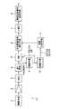
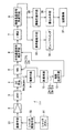
図1はこの発明の実施の形態1による撮像装置を示す概略構成図である。図示のように、この撮像装置は、撮像手段1と、増幅手段2と、A/D変換器(ADC)3と、直流成分再生手段(DC再生手段)4と、ホワイトバランス手段5と、分光感度特性補正手段6と、ガンマ(γ)補正手段7と、輝度色差信号生成手段8とを含む。さらに、除算手段12と、係数生成手段13とを有する。
FIG. 1 is a schematic configuration diagram showing an imaging apparatus according to
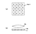
撮像手段1は、例えば図2(a)、(b)に示すように、レンズ10aと、2次元的に配列された複数の光電変換素子を有する撮像素子11と、色分離手段としての色フィルタ10bとを有する。
撮像素子11の複数の光電変換素子は、例えば図2(a)に示すようにベイヤ(Bayer)型に配置された、赤(R)、緑(G)、青(B)の3原色に対応する分光透過率を有する色フィルタ10bで覆われている。
For example, as shown in FIGS. 2A and 2B, the image pickup means 1 includes a
The plurality of photoelectric conversion elements of the
レンズ10aから入射した光は、撮像素子11の受光面上に結像する。撮像素子11は、上記のように、色フィルタ10bで覆われており、各光電変換素子からは、色フィルタ10b分光透過率に対応した色成分、即ちR、G、Bのアナログ映像信号R1、G1、B1が出力される。
The light incident from the
このようにして、撮像手段1から出力されるR、G、Bのアナログ信号(以下、それぞれ「R信号」、「G信号」、「B信号」と言うことがある)は、増幅手段2によって増幅される。増幅手段2から出力された映像信号はADC3によってディジタル信号に変換される。ディジタル信号に変換された映像信号はDC再生手段4により、DCレベルが再生される。DC再生は通常映像信号の黒レベルが「0」になるように、ADC3によるA/D変換前に有していたオフセットレベルをDCシフトするか、クランプ処理を行う。
In this way, the R, G, B analog signals output from the image pickup means 1 (hereinafter may be referred to as “R signal”, “G signal”, and “B signal”, respectively) are amplified by the amplification means 2. Amplified. The video signal output from the amplifying
積算手段9は、DC再生手段4から出力されるR信号、G信号、及びB信号をそれぞれ複数の画素に亘って、例えば画面全体に亘って積算し、R信号の積算値ΣR、G信号の積算値ΣG、及びB信号の積算値ΣB及びを求める。
The integrating
次に、ホワイトバランス(WB)手段5は、それぞれR、G、B信号を増幅する3つの増幅手段(図示しない)を有し、DC再生手段4からのR、G、B信号を受けて、さらに、積算手段9から積算値ΣR、ΣG、ΣBを受けて、映像信号の撮像条件に応じて被写体の白の箇所のR、G、B信号の値が等しくなる(すなわち白の箇所が無彩色になる)ような処理を施す。通常、ホワイトバランス手段5は一般被写体の、画面内のすべての画素についての積算した色は無彩色であるというエバンスの原理に基づき、積算値ΣR、ΣB、ΣGの値が等しくなるように3つの増幅手段の利得を変化させてホワイトバランスを行う。
Next, the white balance (WB) means 5 has three amplifying means (not shown) for amplifying the R, G, B signals, respectively, and receives the R, G, B signals from the DC reproducing means 4, Further, the integrated values ΣR, ΣG, and ΣB are received from the integrating
上記の撮像手段1、増幅手段2、ADC3、DC再生手段4、ホワイトバランス手段5、及び積算手段9により、入射光を受けて、入射光に対応したR、G、Bの色信号を出力する色信号生成手段20が構成されている。
The imaging means 1, amplification means 2, ADC 3, DC reproducing means 4, white balance means 5, and integrating
除算手段12は、積算手段9からR信号の積算値ΣRと、B信号の積算値ΣBと、G信号の積算値ΣGとを受けて、これらの積算値の相互間の比ΣR/ΣG及びΣB/ΣGを算出して出力する。
The dividing means 12 receives the integrated value ΣR of the R signal, the integrated value ΣB of the B signal, and the integrated value ΣG of the G signal from the integrating
係数生成手段13は、除算手段12の出力に基いて後述のようにして係数を決定する。
係数生成手段13は、除算手段12で求めた積算値の比に応じて係数を算出して出力するものであっても良く、また、予め数種の定数の組を記憶しておき、比に応じてそれらから最適のものを選択して出力するものであっても良い。
後述のように、分光感度特性補正手段6のマトリクス演算手段67は、係数生成手段13から出力された係数を用いて、マトリクス演算を行う。
The
The coefficient generating means 13 may calculate and output a coefficient according to the ratio of the integrated values obtained by the dividing means 12, or may store several sets of constants in advance, Accordingly, an optimum one may be selected and output from them.
As will be described later, the
分光感度特性補正手段6は、ホワイトバランス手段5から出力されたホワイトバランス後のR、G、B信号R5、G5、B5を入力とし、それぞれの信号を後述するマトリクス演算することにより撮像手段1の近赤外領域の感度特性による色再現性への影響を補正したカラー信号R6、G6、B6を出力する。
The spectral sensitivity
ガンマ補正手段7は分光感度特性補正手段6から出力された映像信号R6、G6、B6に非線形の階調変換を行う。
The gamma correction unit 7 performs non-linear gradation conversion on the video signals R6, G6, and B6 output from the spectral sensitivity
輝度色差信号生成手段8はガンマ補正手段7から出力されたR、G、B信号R7、G7、B7を輝度信号(Y信号)、及び2つの色差信号(Cr信号、Cb信号)に変換する。輝度色差信号生成手段8は、この変換(YCrCb変換)においては、通常3行3列の係数マトリクスを掛ける、下記の式(2)の線形マトリクス演算を行ってY、Cr、Cb信号を生成する。 The luminance color difference signal generation means 8 converts the R, G, B signals R7, G7, B7 output from the gamma correction means 7 into a luminance signal (Y signal) and two color difference signals (Cr signal, Cb signal). In this conversion (YCrCb conversion), the luminance / chrominance signal generation means 8 performs a linear matrix operation of the following equation (2), which is usually multiplied by a coefficient matrix of 3 rows and 3 columns, to generate Y, Cr, and Cb signals. .

式(2)において3行3列のマトリクス係数は例えば、IEC(International Electrotechnical Commission)61966−2−1)に規定されているように、y1=0.2990、y2=0.5870、y3=0.1140、cr1=−0.1687、cr2=−0.3313、cr3=0.5000、cb1=0.5000、cb2=−0.4187、cb3=−0.0813と定める。 In the formula (2), the matrix coefficient of 3 rows and 3 columns is defined by, for example, IEC (International Electrotechnical Commission) 61966-2-1), y1 = 0.2990, y2 = 0.5870, y3 = 0 1140, cr1 = −0.1687, cr2 = −0.3313, cr3 = 0.5000, cb1 = 0.5000, cb2 = −0.4187, cb3 = −0.0813.
分光感度特性補正手段6についてその構成と原理を以下に説明する。
分光感度特性補正手段6は、色信号生成手段20と分光感度特性補正手段6の総合的な特性が、人間の色覚特性又はそれを線形変換することによって得られる分光感度特性に近似したものとなり、前記色信号生成手段の近赤外域での応答特性を補正するためのものである。
The configuration and principle of the spectral sensitivity
The spectral sensitivity characteristic correction means 6 is such that the overall characteristics of the color signal generation means 20 and the spectral sensitivity characteristic correction means 6 approximate human color vision characteristics or spectral sensitivity characteristics obtained by linearly transforming them. This is for correcting the response characteristic in the near infrared region of the color signal generating means.
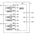
図3は分光感度特性補正手段6の構成を示す概略構成図である。ホワイトバランス手段5から出力されたR、G、Bの色信号R5、G5、B5は分光感度特性補正手段6に入力される。分光感度特性補正手段6は、fi変換手段61、63、65と、fj変換手段62、64、66と、入力される各信号とそれぞれに対する係数との乗算を行ない、乗算結果を加算する3行9列マトリクス演算手段67とを有する。
FIG. 3 is a schematic configuration diagram showing the configuration of the spectral sensitivity
fi変換手段61、63、65は、入力信号R5、G5、B5に対し、1より小さい所定の実数iを指数とするべき乗により得られる値に近似した値を出力するものであり、より詳しく言うと、fi変換手段61、63、65は、概して、(即ち、入力が取り得る範囲のうちの大部分の領域において)、より具体的には、入力が取り得る範囲のうちの最小値に近い領域以外の領域において、入力信号R5、G5、B5に対して上記の実数iを指数としてべき乗することによって得られる値を有し、入力信号が零に近い範囲においては、上記のべき乗により得られる値よりも小さな値に制限された値を有する信号を出力する。例えば、入力信号が零に近い範囲においては、入力信号に対する出力信号の比が所定値以下に制限される。
fj変換手段62、64、66は、入力信号R5、G5、B5に対し、1より大きい所定の実数jを指数とするべき乗により得られる値に近似した値を出力するものであり、より詳しく言うと、fj変換手段62、64、66は、概して、(即ち、入力が取り得る範囲のうちの大部分の領域において)、より具体的には、入力が取り得る範囲のうちの最大値に近い領域以外の領域において、入力信号R5、G5、B5に対して上記の実数jを指数としてべき乗することによって得られる値を有し、入力信号が最大値に近い範囲においては、上記のべき乗により得られる値よりも小さな値に制限された値を有する信号を出力する。例えば、入力信号が最大値に近い範囲においては、入力信号に対する出力信号の比が所定値以下に制限される。
The fi conversion means 61, 63, and 65 output values approximate to values obtained by exponentiation with a predetermined real number i smaller than 1 for the input signals R5, G5, and B5. And the fi conversion means 61, 63, 65 generally (ie, in most areas of the range that the input can take), more specifically, close to the minimum value of the range that the input can take. In a region other than the region, it has a value obtained by exponentiating the real number i with respect to the input signals R5, G5, and B5, and when the input signal is close to zero, it is obtained by the above power. A signal having a value limited to a value smaller than the value is output. For example, in the range where the input signal is close to zero, the ratio of the output signal to the input signal is limited to a predetermined value or less.
The fj conversion means 62, 64, and 66 output values approximate to values obtained by exponentiation with a predetermined real number j greater than 1 for the input signals R5, G5, and B5. And the fj conversion means 62, 64, 66 are generally (ie, in most areas of the range that the input can take), more specifically, close to the maximum value of the range that the input can take. In a region other than the region, the input signal R5, G5, B5 has a value obtained by exponentiation of the real number j as an exponent, and in the range where the input signal is close to the maximum value, it is obtained by the above power. A signal having a value limited to a value smaller than a given value is output. For example, in the range where the input signal is close to the maximum value, the ratio of the output signal to the input signal is limited to a predetermined value or less.
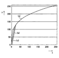
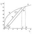
3つのfi変換手段61、63、65の入出力特性は互いに同じであり、その一例を図4及び図5に示す。図4で横軸は入力x(x=R5、G5又はB5)を示し、縦軸は出力y(y=fi(R5)、fi(G5)又はfi(B5))を示す。図5は、図4のうちの入出力の小さい部分を拡大して示す。
例えば、上記の第1の実数iが0.3である場合、fi変換手段61、63、65は、概して(即ち、入力が取り得る範囲のうちの大部分の領域において)、より具体的には、入力が取り得る範囲のうちの最小値に近い領域以外の領域において、入力信号xの0.3乗に比例した値を出力するものであるが、入力信号xが0に近い所定の値xt1よりも小さい範囲では、0.3乗よりも小さい値、例えばk1・xに制限する。ここで、k1は定数であり、例えば「6」に定められる。またxt1は例えば「20」である。
図4及び図5で、xの0.3乗を曲線(a)で示す。これらの図では、入力信号xが取り得る値の最小値が「0(ゼロ)」、最大値が「255」、出力信号yが取り得る値の最小値が「0(ゼロ)」であり、最大値が8ビットを想定して「255」であり、入力に対する出力の関係は、最大値により正規化した値相互間の関係である。即ち、図のxとyとの間には、
(y/255)=(x/255)0.3
という関係がある。
また、k1・xを直線(b)で示す。
x=xt1において、直線(b)と曲線(a)とが交わっている。
この結果、x=xt1よりも小さい範囲においては、出力yは、k1・xであり、xがxt1以上の範囲では、出力yを正規化した値はxを正規化した値の0.3乗となる。
The input / output characteristics of the three
For example, when the first real number i is 0.3, the fi conversion means 61, 63, 65 are generally more specific (that is, in most of the possible range of input). Outputs a value proportional to the 0.3th power of the input signal x in a region other than the region close to the minimum value in the possible range of the input, but the input signal x is a predetermined value close to 0 In a range smaller than xt1, the value is limited to a value smaller than 0.3, for example, k1 · x. Here, k1 is a constant, and is set to “6”, for example. Xt1 is “20”, for example.
4 and 5, x to the power of 0.3 is indicated by a curve (a). In these figures, the minimum value that the input signal x can take is “0 (zero)”, the maximum value is “255”, and the minimum value that the output signal y can take is “0 (zero)”. The maximum value is “255” assuming 8 bits, and the relationship of output to input is the relationship between values normalized by the maximum value. That is, between x and y in the figure,
(Y / 255) = (x / 255) 0.3
There is a relationship.
Further, k1 · x is indicated by a straight line (b).
At x = xt1, the straight line (b) and the curve (a) intersect.
As a result, in the range smaller than x = xt1, the output y is k1 · x, and in the range where x is greater than or equal to xt1, the value obtained by normalizing the output y is the 0.3th power of the value obtained by normalizing x. It becomes.
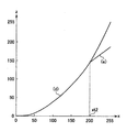
3つのfj変換手段62、64、66の入出力特性は互いに同じであり、その一例を図6に示す。図6で横軸は入力x(x=R5、G5又はB5)を示し、縦軸は出力z(z=fj(R5)、fj(G5)又はfj(B5))を示す。
例えば、上記の第2の実数jが2である場合、fj変換手段62、64、66は、概して(即ち、入力が取り得る範囲のうちの大部分の領域において)、より具体的には、入力が取り得る範囲のうちの最大値に近い領域以外の領域において、入力信号xの2乗に比例した値を出力するものであるが、入力信号xが最大値に近い所定の値xt2よりも大きい範囲では、xの2乗よりも小さい値、例えばk2・xに制限する。ここで、k2は定数であり、例えば1.5に定められる。またxt2は例えば「200」である。
図6で、xの2乗を曲線(a)で示す。この図では、入力信号xが取り得る値の最小値が「0(ゼロ)」、最大値が「255」、出力信号zが取り得る値の最小値が「0(ゼロ)」、最大値が「255」であり、入力に対する出力の関係は、最大値により正規化した値相互間の関係である。即ち、図のxとzとの間には、
(z/255)=(x/255)2
という関係がある。
また、k2・xを直線(b)で示す。
x=xt2において、直線(b)と曲線(a)とが交わっている。
この結果、xがxt2よりも大きい範囲では、出力zは、k2・xでありxがxt2以下の範囲では、出力zを正規化した値はxを正規化した値の2乗となる。
The input / output characteristics of the three fj conversion means 62, 64, and 66 are the same, and an example is shown in FIG. In FIG. 6, the horizontal axis indicates the input x (x = R5, G5 or B5), and the vertical axis indicates the output z (z = fj (R5), fj (G5) or fj (B5)).
For example, when the above second real number j is 2, the fj conversion means 62, 64, 66 generally (ie, in most of the range that the input can take), more specifically, A value proportional to the square of the input signal x is output in a region other than the region close to the maximum value in the range that the input can take, but the input signal x is larger than a predetermined value xt2 close to the maximum value. In a large range, the value is limited to a value smaller than the square of x, for example, k2 · x. Here, k2 is a constant and is set to 1.5, for example. Xt2 is “200”, for example.
In FIG. 6, the square of x is indicated by curve (a). In this figure, the minimum value that the input signal x can take is “0 (zero)”, the maximum value is “255”, the minimum value that the output signal z can take is “0 (zero)”, and the maximum value is “255”, and the relationship of the output to the input is a relationship between values normalized by the maximum value. That is, between x and z in the figure,
(Z / 255) = (x / 255) 2
There is a relationship.
Further, k2 · x is indicated by a straight line (b).
At x = xt2, the straight line (b) and the curve (a) intersect.
As a result, in the range where x is greater than xt2, the output z is k2 · x, and in the range where x is equal to or less than xt2, the value obtained by normalizing the output z is the square of the value obtained by normalizing x.
以下の説明で、fi変換手段61、63、65による変換を単に「fi変換」と言い、fj変換手段62、64、66による変換を単に「fj変換」と言うことがある。 In the following description, the conversion by the fi conversion means 61, 63, 65 may be simply referred to as “fi conversion”, and the conversion by the fj conversion means 62, 64, 66 may be simply referred to as “fj conversion”.
R信号R5はそのままマトリクス演算手段67の入力端子601に入力されるとともに、fi変換手段61及びfj変換手段62に入力され、これらの出力(fi(R5)、fj(R5))がマトリクス演算手段67の入力端子602、603に入力される。
同様に、G信号G5はそのままマトリクス演算手段67の入力端子604に入力されるとともに、fi変換手段63及びfj変換手段64に入力され、これらの出力(fi(G5)、fj(G5))がマトリクス演算手段67の入力端子605、606に入力される。
同様に、B信号B5はそのままマトリクス演算手段67の入力端子607に入力されるとともに、fi変換手段65及びfj変換手段66に入力され、これらの出力(fi(B5),fj(B5))がマトリクス演算手段67の入力端子608、609に入力される。
The R signal R5 is input as it is to the
Similarly, the G signal G5 is directly input to the
Similarly, the B signal B5 is input as it is to the
マトリクス演算手段67は、3行9列のマトリクス係数を掛けるマトリクス演算を行うものであり、3行9列の係数マトリクスを用いてマトリクス演算を行い、R、G、Bの色信号R6、G6、B6を生成する。演算により求められたR、G、B信号R6、G6、B6はそれぞれ、端子651、652、653から出力される。
The matrix calculation means 67 performs a matrix calculation by multiplying a matrix coefficient of 3 rows and 9 columns, performs a matrix calculation using a coefficient matrix of 3 rows and 9 columns, and performs R, G, and B color signals R6, G6, B6 is generated. The R, G, and B signals R6, G6, and B6 obtained by the calculation are output from
マトリスク手段67は、例えば以下の式(1)のマトリクス演算を行うものである。 The mat risk means 67 performs, for example, matrix calculation of the following formula (1).
式(1)において、r1乃至r9、g1乃至g9、及びb1乃至b9は後述のようにして定められる係数である。 In Expression (1), r1 to r9, g1 to g9, and b1 to b9 are coefficients determined as described below.
定数i、j及び係数r1乃至r9、g1乃至g9、及びb1乃至b9は、色信号生成手段20と分光感度特性補正手段6の総合的な特性が、人間の色覚特性又はそれを線形変換することによって得られる分光感度特性に近似したものとなり、前記色信号生成手段の近赤外域での応答特性を補正するように定められものであり、光源の色温度に応じて、即ち、ΣR/ΣG及びΣB/ΣGに応じて変更される。 The constants i and j and the coefficients r1 to r9, g1 to g9, and b1 to b9 indicate that the overall characteristics of the color signal generation means 20 and the spectral sensitivity characteristic correction means 6 are human color vision characteristics or linearly convert them. Is approximated to the spectral sensitivity characteristic obtained by the above, and is determined so as to correct the response characteristic in the near-infrared region of the color signal generating means, depending on the color temperature of the light source, that is, ΣR / ΣG and It is changed according to ΣB / ΣG.
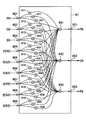
マトリクス演算手段67は、例えば図7に示すように構成される。図示のようにこのマトリクス演算手段67は、27個の乗算手段(611乃至639)と3個の加算手段(641、642、643)とを有する。 The matrix calculation means 67 is configured as shown in FIG. 7, for example. As shown in the figure, the matrix calculation means 67 has 27 multiplication means (611 to 639) and 3 addition means (641, 642, 643).
乗算手段611乃至619は、それぞれ端子601、604、607、602、605、608、603、606、609に入力される信号R5、G5、B5、fi(R5)、fi(G5)、fi(B5)、fj(R5)、fj(G5)、fj(B5)に所定の係数r1、r2、r3、r4、r5、r6、r7、r8、r9を掛けて、乗算結果を加算手段641に出力する。加算手段641は入力の総和を求め、信号R6として出力する。
乗算手段621乃至629は、それぞれ端子601、604、607、602、605、608、603、606、609に入力される信号R5、G5、B5、fi(R5)、fi(G5)、fi(B5)、fj(R5)、fj(G5)、fj(B5)に所定の係数g1、g2、g3、g4、g5、g6、g7、g8、g9を掛けて、乗算結果を加算手段642に出力する。加算手段642は入力の総和を求め、信号G6として出力する。
乗算手段631乃至639は、それぞれ端子601、604、607、602、605、608、603、606、609に入力される信号R5、G5、B5、fi(R5)、fi(G5)、fi(B5)、fj(R5)、fj(G5)、fj(B5)に所定の係数b1、b2、b3、b4、b5、b6、b7、b8、b9を掛けて、乗算結果を加算手段643に出力する。加算手段643は入力の総和を求め、信号B6として出力する。
Multiplication means 611 to 619 respectively receive signals R5, G5, B5, fi (R5), fi (G5), fi (B5) input to
The multiplying means 621 to 629 respectively receive signals R5, G5, B5, fi (R5), fi (G5), fi (B5) inputted to the
Multiplication means 631 to 639 respectively receive signals R5, G5, B5, fi (R5), fi (G5), fi (B5) input to
なお、図7に示したマトリクス演算手段は式(1)で示した演算を実現するための一例であり、他の構成の演算手段で式(1)の演算を実現しても同様の効果が得られる。 Note that the matrix calculation means shown in FIG. 7 is an example for realizing the calculation shown in Expression (1), and the same effect can be obtained even if the calculation of Expression (1) is realized by calculation means of other configurations. can get.
マトリクス演算手段67の乗算手段611乃至639で用いられる係数は、以下のように定められる。
The coefficients used in the
まず、本発明の分光感度特性補正手段6による補正の原理を説明する。
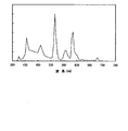
図8に人間の色覚特性を表した分光感度特性を示す。図8に示した特性は正常色覚者の等色関数の平均値であり、CIE(Commission Internationale de l‘E’clairage)1931にて規定されている。人間が感じる色は色順応などの機能を無視し、簡単に表せば図8に示したR、G、Bの分光感度特性(等色関数)と被写体の反射分光特性と照明の分光特性とを乗算し、乗算結果を可視域にて積算することにより得られる値として表すことができる。図8に示したように人間の感度特性はいわゆる可視域と呼ばれるように略380nmから780nmまでしか感度が無く、700nmより長波長側ではほとんど感度特性がない。
First, the principle of correction by the spectral sensitivity
FIG. 8 shows spectral sensitivity characteristics representing human color vision characteristics. The characteristic shown in FIG. 8 is an average value of the color matching function of a normal color vision person, and is defined by CIE (Commission Internationale de l'E'claage) 1931. The colors that humans feel ignore the functions such as chromatic adaptation, and if expressed simply, the spectral sensitivity characteristics (color matching function) of R, G, B shown in FIG. 8, the reflection spectral characteristics of the subject, and the spectral characteristics of the illumination are shown. It can be expressed as a value obtained by multiplying and multiplying the multiplication results in the visible range. As shown in FIG. 8, the human sensitivity characteristic has a sensitivity only from about 380 nm to 780 nm as called a so-called visible range, and has almost no sensitivity characteristic at a wavelength longer than 700 nm.
それに対して、撮像手段1は光電変換を行うフォトダイオードがSi(シリコン)などの半導体で形成されているため、感度特性は可視域から近赤外領域(1000nm近辺)まで感度特性を有する。よって、撮像手段1に色分解を行うRGBの色フィルタ10bを設けた場合、色フィルタの分光特性とフォトダイオードの感度特性の積に応じたR、G、Bの信号が撮像手段1から出力される。
On the other hand, since the photodiode for performing photoelectric conversion is formed of a semiconductor such as Si (silicon), the
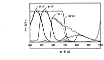
図9に撮像手段1のR,G,B信号の分光感度特性r(λ)、g(λ)、b(λ)を実線で示す。図9に示すようにRの色フィルタは近赤外領域の透過率も比較的高いため、近赤外線を撮像素子11に入射させる。また、Bの光を入射するためのBの色フィルタや、Gの光を入射するためのGの色フィルタも同様に近赤外領域に一定の透過率を有する。これは、RGBの色フィルタは通常それぞれの色を含んだ染料や顔料を用いてフィルタを構成するが、その分光透過率は構成する材質に依存し、長波長側の可視域から近赤外領域に掛けて再び透過率が上がる特性を有しているためである。
FIG. 9 shows the spectral sensitivity characteristics r (λ), g (λ), and b (λ) of the R, G, and B signals of the imaging means 1 by solid lines. As shown in FIG. 9, since the R color filter has a relatively high transmittance in the near infrared region, the near infrared light is incident on the
図9に実線で示した撮像手段1のRGBの分光感度特性r(λ)、g(λ)、b(λ)は図8に示した等色関数とは異なり、特に近赤外領域では著しく異なるため、通常の撮像装置では近赤外領域の光を通過させず除去する赤外カットフィルタ(IRCF)を撮像素子の前に設けている。IRCFの分光透過特性IRCF(λ)も図9に実線で示されている。IRCF(λ)とRGBの分光感度特性(r(λ)、g(λ)、b(λ))とを掛け合わせた特性が従来のIRCFを具備した場合の撮像手段1のRGB信号に対応するそれぞれの色の分光感度特性r’(λ)、g’(λ)、b’(λ)となり、図9の破線でその特性を示す。 The spectral sensitivity characteristics r (λ), g (λ), and b (λ) of RGB of the image pickup means 1 shown by the solid line in FIG. 9 are different from the color matching functions shown in FIG. Because of the difference, an ordinary image pickup apparatus is provided with an infrared cut filter (IRCF) that removes light in the near infrared region without passing it in front of the image sensor. The spectral transmission characteristic IRCF (λ) of IRCF is also shown by a solid line in FIG. A characteristic obtained by multiplying IRCF (λ) and RGB spectral sensitivity characteristics (r (λ), g (λ), b (λ)) corresponds to the RGB signal of the imaging means 1 when the conventional IRCF is provided. The spectral sensitivity characteristics r ′ (λ), g ′ (λ), and b ′ (λ) of the respective colors are shown, and the characteristics are indicated by broken lines in FIG.
また、従来の撮像装置では図9の破線で表した分光感度特性とした場合でも、図8で示した負の特性は実現できないため、撮像手段から得られたRGB信号を式(3)で示すように3行3列の係数マトリクスを掛けるマトリクス演算を行いその色補正を行っていた。 Further, even when the conventional imaging apparatus has the spectral sensitivity characteristic represented by the broken line in FIG. 9, the negative characteristic shown in FIG. 8 cannot be realized. Therefore, the RGB signal obtained from the imaging means is expressed by Equation (3). In this way, the matrix correction is performed by multiplying the coefficient matrix of 3 rows and 3 columns to correct the color.
しかしながら、IRCFを用いない場合には、近赤外線による感度特性によって出力される信号が色再現性に与える影響が大きく、上記のような3行3列の係数マトリクスを掛ける線形マトリクス演算を行っても良好な色再現性が得られない。これに対して、本発明では図9に実線で示した、IRCFを用いない場合の撮像素子1の分光感度特性r(λ)、g(λ)、b(λ)の、近赤外領域のRGBそれぞれの感度特性相互間の差を利用して良好な色再現性を実現している。
However, when IRCF is not used, the signal output by the sensitivity characteristic by near infrared rays has a great influence on the color reproducibility, and even if linear matrix calculation is performed by multiplying the coefficient matrix of 3 rows by 3 columns as described above. Good color reproducibility cannot be obtained. On the other hand, in the present invention, the spectral sensitivity characteristics r (λ), g (λ), and b (λ) of the
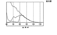
図10に図9に示した分光感度特性の近赤外領域の拡大図を示す。R、G、Bのフィルタとフォトダイオードを組合せたものの分光感度特性は略850nmから860nm近辺でその感度が一致して、それより波長が長くなるにつれて、同様に減衰していく。また、Gの分光感度特性は略650nm近辺まで一旦減衰しその後透過率を上げて略850nm近辺をピークに減衰していく。Bの分光感度特性は略760nm近辺から透過率を上げ同様に略850nm近辺でピークとなり、それより長い波長領域では次第に減衰していく。 FIG. 10 shows an enlarged view of the near infrared region of the spectral sensitivity characteristics shown in FIG. The spectral sensitivity characteristics of the combination of the R, G, and B filters and the photodiodes match in the vicinity of about 850 nm to 860 nm, and similarly attenuate as the wavelength becomes longer. Further, the spectral sensitivity characteristic of G is once attenuated to about 650 nm, and then the transmittance is increased to attenuate the peak at about 850 nm. The spectral sensitivity characteristic of B increases the transmittance from around 760 nm and similarly peaks at around 850 nm, and gradually attenuates in a longer wavelength region.
このように、略650nmから800nmまでの領域においてRの分光感度特性r(λ)とGの分光感度特性g(λ)とBの分光感度特性b(λ)との間にそれぞれ差異が生じるため、この差異を利用して近赤外領域におけるRGBの色分離を行うことができ、近赤外線の影響による色再現性に補正を加えることができることとなる。 Thus, in the region from approximately 650 nm to 800 nm, there is a difference between the R spectral sensitivity characteristic r (λ), the G spectral sensitivity characteristic g (λ), and the B spectral sensitivity characteristic b (λ). Using this difference, RGB color separation in the near infrared region can be performed, and color reproducibility due to the influence of the near infrared ray can be corrected.
具体的には、マトリクスの演算に非線形の演算を含ませる。
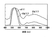
例えば図11にGの分光感度特性をg(λ)として示す。
また、図11に前記のGの分光感度特性をfi変換することにより得られる特性、即ちiを指数とするべき乗、例えば0.3乗し、その最大値で正規化した特性をfi(g(λ))として示す。
さらに図11に前記Gの分光感度特性をfj変換することにより得られる特性、即ちjを指数とするべき乗、例えば2乗し、その最大値で正規化した特性をfj(g(λ))として示す。
図11に示すようにfi変換により得られた分光感度特性は、不必要とする近赤外側の分光感度特性と必要とする可視域の分光感度特性との感度差が小さくなり、
fj変換により得られた分光感度特性は、不必要とする近赤外側の分光感度特性と必要とする可視域の分光感度特性との感度差が大きくなる。よって、fi変換により得られた値係数との積と、fj変換により得られた値と係数との積を含むマトリクス演算、即ち、非線形マトリクス演算により、
赤外領域を含む赤外光を入射した際にも、適切な色補正を行い、良好な色再現性を得ることができる。
ここでの色再現性とは人間の目で見える色に略一致させることであり、かつ目で違うものに見える色は違う色に、同じものに見える色は同じ色に再現することを意味する。
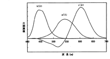
Specifically, a nonlinear calculation is included in the matrix calculation.
For example, FIG. 11 shows the spectral sensitivity characteristic of G as g (λ).
FIG. 11 shows a characteristic obtained by performing the fi conversion on the spectral sensitivity characteristic of G, that is, a characteristic obtained by multiplying i by an exponent, for example, 0.3, and normalized by the maximum value fi (g ( λ)).
Further, FIG. 11 shows a characteristic obtained by fj conversion of the spectral sensitivity characteristic of G, that is, a characteristic obtained by multiplying j to an exponent, for example, a square, and normalized by the maximum value as fj (g (λ)). Show.
As shown in FIG. 11, the spectral sensitivity characteristic obtained by fi conversion reduces the sensitivity difference between the unnecessary near-infrared spectral sensitivity characteristic and the required visible spectral sensitivity characteristic,
The spectral sensitivity characteristic obtained by the fj conversion has a large sensitivity difference between the unnecessary near-infrared spectral sensitivity characteristic and the required visible spectral sensitivity characteristic. Therefore, a matrix operation including a product of the value coefficient obtained by the fi conversion and a product of the value and the coefficient obtained by the fj conversion, that is, a non-linear matrix operation,
Even when infrared light including an infrared region is incident, appropriate color correction can be performed and good color reproducibility can be obtained.
The color reproducibility here means to match the colors that are visible to the human eye, and colors that look different to the eyes will be reproduced as different colors, and colors that appear to be the same will be reproduced as the same color. .
例えば、色信号生成手段20と分光感度特性補正手段6における補正の総合的な特性が、CIE1931等色関数又はCIE1931等色関数を線形変換することにより得られた等色関数に近似したものとなるように上記のマトリクス演算で用いられる係数r1乃至r9、g1乃至g9、およびb1乃至b9及び定数i、jを定めることとする。
For example, the overall characteristics of correction in the color
ここで、fi変換手段(61、63、65)及びfj変換手段(62、64、66)を用いて入力のべき乗そのものではなく、それに近似した値を用いる理由を説明する。
先にも述べたように、第1の定数が0.3であるとき、最大値で正規化した入力信号と最大値で正規化した出力信号の関係は図4に曲線(a)で示す通りである。
ここで、入力信号の最大値、出力信号の最大値は「255」としている。
この場合、入力信号の値が小さい範囲では、利得(入力信号に対する出力信号の比)が極めて大きい。例えば、入力信号の値が「1」のとき、出力信号の値は、「48」である。即ち、48倍(34dB)もの利得が与えられたこととなる。このため、映像信号が小さい範囲では、一定のノイズ、例えば暗電流による固定パターンノイズ(FPN)が増幅され、映像信号のS/Nが極めて劣化することとなる。
本実施の形態では、上記のように、入力信号が小さい範囲では、利得を0.3乗により得られる値より小さくする。これにより、S/Nの劣化を低減することができる。
具体的には図4(b)及び図5(b)に示すように入力信号が零に近いxt1(例えばxt1=20)よりも小さい範囲では、出力信号の値yをy=k1・x以下(k1は傾きを表す定数であり、例えば「6」)に制限することとしている。この結果、上記の問題が解決する。
Here, the reason for using the fi conversion means (61, 63, 65) and the fj conversion means (62, 64, 66), not the power of the input itself, but a value approximated thereto will be described.
As described above, when the first constant is 0.3, the relationship between the input signal normalized by the maximum value and the output signal normalized by the maximum value is as shown by the curve (a) in FIG. It is.
Here, the maximum value of the input signal and the maximum value of the output signal are “255”.
In this case, the gain (ratio of the output signal to the input signal) is extremely large in the range where the value of the input signal is small. For example, when the value of the input signal is “1”, the value of the output signal is “48”. That is, a gain of 48 times (34 dB) is given. For this reason, in a range where the video signal is small, fixed noise, for example, fixed pattern noise (FPN) due to dark current is amplified, and the S / N of the video signal is extremely deteriorated.
In the present embodiment, as described above, the gain is made smaller than the value obtained by the power of 0.3 in the range where the input signal is small. Thereby, S / N degradation can be reduced.
Specifically, as shown in FIGS. 4B and 5B, in the range where the input signal is smaller than xt1 close to zero (for example, xt1 = 20), the value y of the output signal is y = k1 · x or less. (K1 is a constant representing an inclination, and is limited to, for example, “6”). As a result, the above problem is solved.
同様に、fj変換手段は1より大きい値j、例えば2を指数としてべき乗することにより得られる値に近似する値の色信号を出力するものであり、fi変換手段同様にjを指数とするべき乗により利得が大きくなる範囲、即ち最大値(「255」)に近い値xt2よりも大きい範囲において、利得を、制限することで、S/Nの劣化を抑制している。
具体的には、fj変換手段は、図6に直線(e)で示すように、入力信号が最大値に近いxt2(例えばxt2=200)よりも大きい範囲では、出力信号の値yをy=k2・x以下(k2は傾きを表す定数であり、例えば「1.5」)に制限することとしている。
Similarly, the fj conversion means outputs a color signal having a value approximate to a value obtained by exponentiation of a value j greater than 1, for example, 2 as an exponent, and similar to the fi conversion means, the power of j being an exponent. S / N degradation is suppressed by limiting the gain in the range in which the gain increases, that is, in the range larger than the value xt2 close to the maximum value (“255”).
Specifically, as shown by a straight line (e) in FIG. 6, the fj conversion means sets the value y of the output signal to y = in the range where the input signal is larger than xt2 (for example, xt2 = 200) close to the maximum value. It is supposed to be limited to k2 · x or less (k2 is a constant representing a slope, for example, “1.5”).
なお、上記の実施の形態における分光感度特性補正手段のfi変換手段61、63、65及びfj変換手段62、64、66は、入力(アドレス)の値をべき乗した値に近似した値を(そのアドレスのデータとして)出力するLUT(ルックアップテーブル)で構成しても良い。 It should be noted that the fi conversion means 61, 63, 65 and the fj conversion means 62, 64, 66 of the spectral sensitivity characteristic correction means in the above embodiment have values approximated to the power of the input (address) value (that is, An LUT (lookup table) to be output (as address data) may be used.
以下、マトリクス演算手段67で用いられる係数を比ΣR/ΣG及び比ΣB/ΣGに基づいて変更することの意義について説明する。
撮像手段1から出力されるR、G、B信号R1、G1、B1は被写体の分光反射特性と、照明の分光特性と、撮像手段1の分光感度特性の積で求まるため、撮像時の照明が変わるとその分光特性も変わる。従って、(これに対する補正を加えなければ)撮像装置から得られる色再現性も照明ごとに異なることになる。
通常撮像装置と人間の色彩に関する分光感度特性(等色関数)が完全に一致していなくても人間の分光感度特性の線形変換で成り立つルータ条件を満たしていればよい。
Hereinafter, the significance of changing the coefficients used in the matrix calculation means 67 based on the ratio ΣR / ΣG and the ratio ΣB / ΣG will be described.
Since the R, G, B signals R1, G1, and B1 output from the
Even if the spectral sensitivity characteristics (color matching functions) relating to the colors of the normal imaging apparatus and human are not completely matched, it is sufficient if the router condition established by the linear conversion of the human spectral sensitivity characteristics is satisfied.
通常撮像手段1の分光感度特性は、たとえIRCFを具備したとしても、人間の分光感度特性とは異なる。そこで、従来の撮像装置では、特定の代表的な照明のときのみ良好な色再現性が得られるように前述した式(3)にて示した3行3列のマトリクス演算手段によって人間の見た色に近づくように色調整を行っているが、撮像手段1と人間の目の分光感度特性が一致していないため当然、被写体の照明が異なれば撮像装置の色再現性は異なることになる。なお、特定の照明条件下のみで色再現性が合うことを条件等色という。
The spectral sensitivity characteristics of the normal imaging means 1 are different from human spectral sensitivity characteristics even if the IRCF is provided. In view of this, the conventional imaging apparatus is viewed by humans by the 3 × 3 matrix computing means shown in the above formula (3) so that good color reproducibility can be obtained only with specific representative illumination. Although the color adjustment is performed so as to approach the color, since the spectral sensitivity characteristics of the
ただし、例えば、撮像素子1の分光特性r(λ)、g(λ)、b(λ)(図9に実線で示す)とIRCFの分光特性とを掛けあわせた分光感度特性r’(λ)、g’(λ)、b’(λ)(図9に破線で示す)と、人間の目の分光感度特性は著しく異なっているわけではないため、照明が変わっても大きく色再現性に破綻をきたすことは無く、撮像装置には測色機なみの性能が要求されるわけではなく、従来の民生品などはそれで良しとされている。
However, for example, spectral sensitivity characteristics r ′ (λ) obtained by multiplying the spectral characteristics r (λ), g (λ), b (λ) (shown by solid lines in FIG. 9) of the
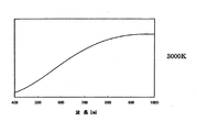
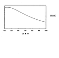
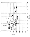
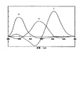
一方、本実施の形態にして示す撮像素子1の分光感度特性はIRCFを具備しないため、図9に実線で示した特性であり、人間の目の分光感度特性と近赤外領域において著しくその特性が異なる。そのため照明が異なると大きく色再現性が異なってしまう。例えば、図12は黒体輻射による3000Kの色温度を有する光源の分光特性である。図13は黒体輻射による6500Kの色温度を有する光源の分光特性である。
これら2種の光源下においては、ホワイトバランスを合わせてもその色再現性が互いに大きく異なる。太陽光は時間や気象条件によってその色温度が変化するが、基本的に黒体輻射の色温度とほぼ相関が取れる。図14にはCIE1931xy色度図における黒体輻射軌跡及び等色温度線を示す。図14に図示するように色温度が変化しても太線で記載しているようにxyは一義的な関係であるため、太陽光源やフィラメントランプなどの場合には、一方の積算値の比ΣR/ΣGに対して、ΣB/ΣGは一義的に得られる関係となる。
On the other hand, the spectral sensitivity characteristic of the
Under these two types of light sources, the color reproducibility is greatly different from each other even if the white balance is adjusted. Although the color temperature of sunlight changes depending on time and weather conditions, it is basically correlated with the color temperature of blackbody radiation. FIG. 14 shows a black body radiation locus and color matching temperature lines in the CIE 1931xy chromaticity diagram. As shown in FIG. 14, even if the color temperature changes, xy has an unambiguous relationship as indicated by the bold line. Therefore, in the case of a solar light source or a filament lamp, the ratio ΣR of one integrated value With respect to / ΣG, ΣB / ΣG is uniquely obtained.
一方、蛍光灯の場合には、黒体輻射軌跡から少し外れる。しかし、黒体輻射軌跡から外れる色であっても、等色温度線(図14中細線)と黒体輻射軌跡との交点を求め、その点における色温度(相関色温度)を有するものとして扱える。しかし、黒体輻射軌跡から外れるにつれてその照明の演色性は劣化していく。そのため、例えば昼白色より、3波長昼白色の蛍光灯の方が演色性がよい。よって、同じ色温度の値であっても、黒体輻射軌跡から外れるにつれて、色再現性を補正するためのマトリクス係数を同値として用いることはできない。
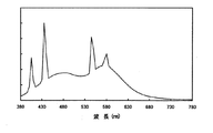
図15は白色蛍光灯、図16は昼光色蛍光灯、図17は3波長型昼光色蛍光灯の分光感度特性である。
On the other hand, in the case of a fluorescent lamp, it slightly deviates from the black body radiation locus. However, even if the color deviates from the black body radiation locus, the intersection of the color matching temperature line (thin line in FIG. 14) and the black body radiation locus can be obtained and treated as having the color temperature (correlated color temperature) at that point. . However, the color rendering properties of the illumination deteriorate as it deviates from the black body radiation locus. For this reason, for example, a three-wave daylight fluorescent lamp has better color rendering than daytime white. Therefore, even if the values of the color temperature are the same, the matrix coefficients for correcting the color reproducibility cannot be used as the same values as they deviate from the black body radiation locus.
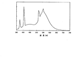
FIG. 15 shows the spectral sensitivity characteristics of the white fluorescent lamp, FIG. 16 shows the daylight fluorescent lamp, and FIG. 17 shows the spectral sensitivity characteristics of the three-wavelength daylight fluorescent lamp.
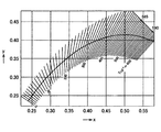
そこで、積算手段9より得たR、G、Bの積算値に応じて係数生成手段13により分光感度特性補正手段6の3行9列のマトリクス係数を変化させる。図18に黒体輻射の様々な色温度の照明下(太陽光やハロゲン等)で積算手段9から得られるR、G、Bの積算値の比を示す。図18中(a)の曲線(四角点)が本発明の構成における積算手段9から得られる値であり、色温度は3000Kから7000Kに対応している。なお、(b)(丸点)は従来の撮像装置から得られる積算値の比であり、図9に示したIRCFの特性を加味した値である。
図18に示すように、その特性はΣR/ΣGとΣB/ΣGの関係が一義的であり、曲線で結ぶことができる。そのため、ΣR/ΣGか、ΣB/ΣGが得られれば黒体輻射上の色温度を推定することができる。
一方、図15から図17に示した蛍光灯は図18の点(三角点)で表す値を示す。蛍光灯は先に示した曲線(a)上には載らず異なった値を持つ。図18中、曲線(a)から破線にて記載している直線は等温度線を示す。
一方、蛍光灯などの場合、ΣR/ΣGとΣB/ΣGとの関係は一義的には求まらず、ΣR/ΣGとΣB/ΣGの両方の値と、等色温度線との関係(ΣR/ΣGとΣB/ΣGの両方の値から、どの等色温度線上にあるか)が分かるので、それに基づいてその相関色温度、及び赤外光を含んだ場合の黒体輻射軌跡(図18中の(b))からどれだけ外れているのかを知ることができる。そこで、求められたΣR/ΣG及びΣB/ΣGに応じて適切なマトリクス係数を分光感度特性補正手段6に与えることにより、光源に応じて良好な色再現性を得ることができる。
例えば、ΣR/ΣG=0.4、ΣB/ΣG=0.6が得られたら、光源は白色蛍光灯と推定し、等色温度線E1上にあり、相関色温度がQ1であることが分る。そこで、色温度Q1に対して適切な係数を選択する。
なお、等温度線や相関色温度との関係を無視し、ΣR/ΣGとΣB/ΣGの値に応じて係数を定めるようにしても良い。
Therefore, the matrix coefficient of the 3 × 9 matrix of the spectral sensitivity
As shown in FIG. 18, the relationship between ΣR / ΣG and ΣB / ΣG is unambiguous and can be connected by a curve. Therefore, if ΣR / ΣG or ΣB / ΣG is obtained, the color temperature on blackbody radiation can be estimated.
On the other hand, the fluorescent lamps shown in FIGS. 15 to 17 show values represented by points (triangular points) in FIG. Fluorescent lamps have different values, not on the curve (a) shown above. In FIG. 18, the straight line described with a broken line from the curve (a) shows an isothermal line.
On the other hand, in the case of a fluorescent lamp or the like, the relationship between ΣR / ΣG and ΣB / ΣG is not uniquely determined, and the relationship between both values of ΣR / ΣG and ΣB / ΣG and the color matching temperature line (ΣR / ΣG and ΣB / ΣG values indicate which color temperature line is present), and based on this, the correlated color temperature and the black body radiation locus in the case of including infrared light (in FIG. 18) It is possible to know how far from (b)). Therefore, by providing the spectral sensitivity characteristic correction means 6 with an appropriate matrix coefficient according to the obtained ΣR / ΣG and ΣB / ΣG, it is possible to obtain good color reproducibility according to the light source.
For example, if ΣR / ΣG = 0.4 and ΣB / ΣG = 0.6 are obtained, it is estimated that the light source is a white fluorescent lamp, is on the color matching temperature line E1, and the correlated color temperature is Q1. The Therefore, an appropriate coefficient is selected for the color temperature Q1.
Note that the coefficient may be determined according to the values of ΣR / ΣG and ΣB / ΣG, ignoring the relationship between the isotherm and the correlated color temperature.
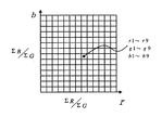
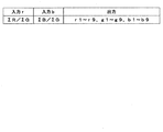
そこで、本実施の形態では、積算手段9から得たR、B、及びGの積算値の比ΣR/ΣG、ΣB/ΣGに応じて係数生成手段13が出力すればよい。実現する手段の一例を図19、図20に示す。図19はΣR/ΣG、ΣB/ΣGを入力とし、マトリクス係数r1からr9、g1からg9、b1からb9の27の値を出力するLUT(Look Up Table)である。入力値ΣR/ΣGが例えば、8bitであれば、256種の入力アドレスと、入力値ΣB/ΣGが8bitであれば、256種の入力アドレスとの組み合わせだけのテーブルが用意されており、それぞれのテーブル内に前記r1からr9、g1からg9、b1からb9の出力値が記憶されている。それぞれのテーブルに対応するだけの光源種は必ずしも存在するわけでないため、先に説明した方法にて求めたターゲットカラーに対応する代表的なマトリクス係数以外のテーブルの場所はそれぞれの値を内挿する形にて記憶しておけばよい。本LUTを具備することにより、係数生成手段13は撮像時の照明に応じて最適な色再現性が得られるマトリクス係数を分光感度特性補正手段6へ出力する。
Therefore, in the present embodiment, the coefficient generating means 13 may output according to the ratios ΣR / ΣG and ΣB / ΣG of the integrated values of R, B, and G obtained from the integrating
適切なマトリクス係数の求め方の一例を示す。例えば、被写体として現存する色を代表するカラーパッチを多く含み、かつ人間の記憶色(肌色、植物の緑、空の青等)を重視した24種のカラーパッチを有するマクベスカラーチェッカー(Macbeth Color Checker(登録商標))が挙げられる。また、カラーターゲットとすべきRGBの分光感度特性として、図21に示すIEC(INTERNATIONAL ELECTROTECHNICAL COMMISSION)61966−2で定められている機器相互間で標準となる等色関数としてsRGBが挙げられる。 An example of how to obtain an appropriate matrix coefficient will be shown. For example, a Macbeth Color Checker (Macbeth Color Checker) that includes many color patches representing existing colors as subjects and has 24 color patches that emphasize human memory colors (skin color, plant green, sky blue, etc.). (Registered trademark)). Further, as RGB spectral sensitivity characteristics to be a color target, sRGB is a standard color matching function between devices defined in IEC (INTERNAL ELECTROTECHNICAL COMMISION) 61966-2 shown in FIG.
そこで、図12、図13に例示した照明及び種々の蛍光灯を含めた色温度の互いに異なる照明の分光特性(既知の値)と上記sRGBの等色関数(既知の値)とカラーパッチのそれぞれのパッチの分光反射特性(既知の値)を掛けあわせ、全波長領域に渡り積算した各パッチのRGB値に対して、ホワイトバランスを行った後の各パッチの色(R,G,B値)がカラーターゲットとなる色再現性とする。 Accordingly, the spectral characteristics (known values) of the illuminations having different color temperatures including the illuminations illustrated in FIGS. 12 and 13 and various fluorescent lamps (known values), the sRGB color matching functions (known values), and the color patches, respectively. Each patch color (R, G, B value) after white balance is applied to the RGB values of each patch multiplied by the spectral reflection characteristics (known values) Is the color reproducibility that becomes the color target.
そして、図9に実線で示した撮像素子1の分光感度特性と、図12、図13に例示した照明及び種々の蛍光灯を含めた色温度の互いに異なる照明の分光特性(既知の値)と、カラーパッチのそれぞれのパッチの分光反射特性(既知の値)を掛け合わせ、全波長領域に対して積算したカラーパッチのRGB値に対して、分光感度特性補正手段6によってマトリクス演算を行うことにより得られるRGB値が、上記のカラーターゲットとしてのRGB値に最も近くなるように分光感度特性補正手段6の3行9列のマトリクス係数を求める。
Then, the spectral sensitivity characteristics of the
カラーターゲットとしてのRGB値と、分光感度特性補正手段6によって求めたRGB値とが最も近いかどうかの判定は、最小二乗法により、即ち両者のそれぞれ対応する値の差の二乗の総和を求めて、この総和が最小かどうかを判定することにより行われる。 Whether or not the RGB value as the color target and the RGB value obtained by the spectral sensitivity characteristic correction means 6 are the closest is determined by the least square method, that is, the sum of the squares of the differences between the two corresponding values. This is done by determining whether this sum is minimum.
なお、上記の例では、積算手段9がDC再生手段4の出力を積算しているが、ADC3の出力を積算するようにしても良く、ホワイトバランス手段5の出力を積算するようにしても良い。
In the above example, the integrating
また、上記の実施の形態では、もともとホワイトバランス手段5における演算のために必要な積算値ΣR、ΣG、ΣBを求める積算手段9の出力を用いて除算手段12における演算を行っている。この場合、積算手段9は、色信号生成手段20の一部であるとともに、それとは異なる役割をも有している。
積算手段9とは別の積算手段を除算手段12のために設けることもできる。
Further, in the above embodiment, the calculation in the dividing means 12 is performed using the output of the integrating
An integrating means different from the integrating
また、上記の実施の形態では、ADC3を設け、それ以降の演算をディジタル信号処理にて行ったが、アナログ信号処理を用いても同様の効果が得られる。
アナログ信号で処理する場合には、fi変換やfj変換を、べき乗値に近似する値の信号を出力するように、入力信号レベルに応じて利得を変化させる増幅手段で構成してもよい。これは、例えばトランジスタと演算増幅器とを組み合わせた回路で実現することができる。
In the above embodiment, the ADC 3 is provided and the subsequent calculation is performed by digital signal processing. However, the same effect can be obtained by using analog signal processing.
In the case of processing with an analog signal, the fi conversion and the fj conversion may be configured by an amplifying unit that changes the gain according to the input signal level so as to output a signal having a value approximate to a power value. This can be realized, for example, by a circuit combining a transistor and an operational amplifier.
さらにまた、上記の実施の形態では、図4の直線(b)により信号利得を制限したが、図4の直線(c1)と(c2)の組合せにより信号利得を制限することもできる。即ちxt3(例えばxt3=5)よりも小さい領域では、y=k3・x(k3はk1よりも小さい定数であり、例えば「2.5」)で表される直線(c1)により制限し、xt3以上でxt4(例えばxt4=24)よりも小さい領域では、x座標値がxt3、y座標値が2.5×xt3の点を通り傾きk4が所定値、例えば「6」であるような直線(c2)により制限することもできる。この場合、入力信号が小さい領域における利得がより小さな値に制限されており、S/Nの劣化を一層抑制することができ、良好なS/Nを得ることができる。 Furthermore, in the above embodiment, the signal gain is limited by the straight line (b) in FIG. 4, but the signal gain can also be limited by a combination of the straight lines (c1) and (c2) in FIG. That is, in a region smaller than xt3 (for example, xt3 = 5), it is limited by a straight line (c1) represented by y = k3 · x (k3 is a constant smaller than k1, for example, “2.5”), and xt3 As described above, in an area smaller than xt4 (for example, xt4 = 24), a straight line having an x coordinate value of xt3 and a y coordinate value of 2.5 × xt3 and a slope k4 of a predetermined value, for example, “6” ( It can also be limited by c2). In this case, the gain in the region where the input signal is small is limited to a smaller value, and the S / N deterioration can be further suppressed, and a good S / N can be obtained.
上記の実施の形態によれば、IRCFを用いなくても、良好な色再現性を得ることができ、また非線形マトリクス演算を行うことで、等色条件を高精度に近似し、良好な色再現性を得ることができることができる。また、S/N(signal to noize ratio)の良い画像を得ることができる。 According to the above embodiment, it is possible to obtain good color reproducibility without using IRCF, and by performing nonlinear matrix calculation, the color matching conditions can be approximated with high accuracy and good color reproduction can be achieved. Sex can be obtained. In addition, an image with good S / N (signal to noise ratio) can be obtained.
上記の実施の形態によれば、照明の色温度に応じてマトリクス係数を変えて、照明の色温度によらず常に良好な色再現性を得ることができる。 According to the above embodiment, it is possible to always obtain good color reproducibility regardless of the illumination color temperature by changing the matrix coefficient in accordance with the illumination color temperature.
実施の形態2.
以上の実施の形態1乃至3において、さらに、分光感度特性補正手段6以降の処理は、特に静止画の場合には、ソフトウェアによって、即ち、プログラムされたコンピュータによって実現することができる。
In the first to third embodiments described above, the processing after the spectral sensitivity
実施の形態3.
以上の実施の形態の撮像装置は、動画や静止画を撮像するビデオカメラ、カメラ一体型VTR、デジタルスチルカメラ、PCカメラ、並びに携帯電話や携帯端末機に内蔵されるデジタルスチルカメラに適用可能であり、これらからIRCFを不要とし、かつ暗視に利用することが多い、監視カメラや車載カメラなどにも適用できる。
Embodiment 3 FIG.
The imaging device of the above embodiment can be applied to a video camera that captures moving images and still images, a camera-integrated VTR, a digital still camera, a PC camera, and a digital still camera built in a mobile phone or a mobile terminal. Therefore, the present invention can be applied to surveillance cameras and in-vehicle cameras that do not require IRCF and are often used for night vision.
図22は、その一例として、図1の撮像装置を用いたデジタルスチルカメラを構成した場合の概略図を示す。
図22に示すディジタルカメラは、図1に示した撮像装置を構成する各要素のうち、撮像手段1の代わりに撮像手段21を備え、さらにシャッタボタン19、シャッタ駆動手段32、表示駆動手段33、ビューファインダ34、画像圧縮手段35、及び書き込み手段36を付加したものである。
FIG. 22 shows a schematic diagram when a digital still camera using the imaging apparatus of FIG. 1 is configured as an example.
The digital camera shown in FIG. 22 includes an image pickup means 21 instead of the image pickup means 1 among the elements constituting the image pickup apparatus shown in FIG. 1, and further includes a shutter button 19, a shutter drive means 32, a display drive means 33, A viewfinder 34, an image compression means 35, and a writing means 36 are added.
撮像手段21が、撮像手段1と異なるのは、図示しないシャッタを備えている点である。
シャッタ駆動手段32は、シャッタボタン19の操作に応じてシャッタを駆動する。
表示駆動手段33は、輝度色差信号生成手段8の出力を受けてビューファインダ34に画像を表示させる。
ビューファインダ34は、例えば液晶表示装置で構成され、表示駆動手段33に駆動されて、撮像手段1で撮像されている画像を表示する。
画像圧縮手段35は、輝度色差信号生成手段8の出力を受けて例えばJPEGに準拠した画像圧縮を行なう。
書き込み手段36は、画像圧縮手段35で圧縮されたデータを記録媒体37に書き込む。
The
The
The display driving unit 33 receives the output of the luminance / color difference
The viewfinder 34 is composed of, for example, a liquid crystal display device, and is driven by the display driving unit 33 to display an image captured by the
The
The
撮像装置を動画撮影に用いて、画像データを図示しない機器に伝送する場合、輝度色差信号生成手段の出力をエンコードしてNTSC信号を生成して出力する。 When the image pickup apparatus is used for moving image shooting and image data is transmitted to a device (not shown), the output of the luminance / color difference signal generation means is encoded to generate and output an NTSC signal.
1 撮像手段、 2 増幅手段、 3 A/D変換器(ADC)、 4 直流成分(DC)再生手段、 5 ホワイトバランス(WB)手段、 6 分光感度特性補正手段、 61、63、65 fi変換手段、 62、64、66 fj変換手段、 67 マトリクス演算手段、 611乃至639 乗算手段、 641、642、643 加算手段、 7 ガンマ(γ)補正手段、 8 輝度色差信号生成手段、 9 積算手段、 10a レンズ、 10b フィルタ、 11 撮像素子、 21 撮像手段、 31 シャッタボタン、 32 シャッタ駆動手段、 33 表示駆動手段、 34 ビューファインダ、 35 画像表示手段、 36 書き込み手段、 37 記録媒体。
DESCRIPTION OF
Claims (12)
前記第1の赤、緑、青の色信号と係数との乗算を含むマトリクス演算を行って第2の赤、緑、青の色信号を生成する分光感度特性補正手段とを備え、
前記分光感度特性補正手段は、
前記第1の赤、緑、青の色信号と、前記第1の赤、緑、青の色信号に予め定めた第1の定数を指数としてべき乗することによって得られる値に近似した値を有する赤、緑、青の第3の色信号と、前記第1の赤、緑、青の色信号に予め定めた第2の定数を指数としてべき乗することによって得られる値に近似した値を有する赤、緑、青の第4の色信号と、これらに対する係数との乗算と、この乗算の結果の相互加算とを含むマトリクス演算を行い、
前記第1の定数、前記第2の定数、及び前記係数は、前記色信号生成手段と前記分光感度特性補正手段の総合的な特性が、人間の色覚特性又はそれを線形変換することによって得られる分光感度特性に近似したものとなり、前記色信号生成手段の近赤外域での応答特性を補正するように定められており、
前記色信号生成手段は、前記撮像手段から得られた赤、緑、青の色信号を画面内の複数の画素にわたって積算し、赤の色信号の積算値ΣRと青の色信号の積算値ΣBと、緑の色信号の積算値ΣGとを求める積算手段を有し、
前記積算手段により求められた赤の色信号の積算値ΣRと、青の色信号の積算値ΣBと、緑の色信号の積算値ΣGとを求め、これらの比ΣR/ΣG及びΣB/ΣGを計算する除算手段と、
前記比ΣR/ΣG及びΣB/ΣGの値に応じて前記分光感度特性補正手段で用いられる前記係数を生成する係数生成手段とを
さらに備える
ことを特徴とする撮像装置。 Color signal generating means for receiving incident light and outputting first red, green, and blue color signals corresponding to the incident light;
Spectral sensitivity characteristic correcting means for generating a second red, green, blue color signal by performing a matrix operation including multiplication of the first red, green, blue color signal and a coefficient;
The spectral sensitivity characteristic correcting means includes:
The first red, green, and blue color signals and the first red, green, and blue color signals have values approximated to values obtained by raising a predetermined first constant as an exponent. Red having a value approximated to a value obtained by exponentiating the third color signal of red, green, and blue and the first red, green, and blue color signal with a predetermined second constant as an exponent A matrix operation including the fourth color signal of green, blue, the multiplication of the coefficients for these signals, and the mutual addition of the results of the multiplication,
The first constant, the second constant, and the coefficient are obtained by a human color vision characteristic or a linear conversion of the color characteristic generation means and the spectral sensitivity characteristic correction means. It is approximated to the spectral sensitivity characteristic, and is defined to correct the response characteristic in the near infrared region of the color signal generating means,
Before Symbol color signal generating means, red obtained from the imaging unit, green, is integrated over a plurality of pixels in a screen No. Iroshin blue, integration of the color signal integrated value ΣR and blue red color signal Integrating means for obtaining the value ΣB and the integrated value ΣG of the green color signal ;
The integrated value ΣR of the red color signal, the integrated value ΣB of the blue color signal, and the integrated value ΣG of the green color signal obtained by the integrating means are obtained, and these ratios ΣR / ΣG and ΣB / ΣG are obtained. A division means to calculate;
An imaging apparatus, further comprising: coefficient generation means for generating the coefficient used by the spectral sensitivity characteristic correction means according to the values of the ratios ΣR / ΣG and ΣB / ΣG.
前記第1の赤、緑、青の色信号と係数との乗算を含むマトリクス演算を行って第2の赤、緑、青の色信号を生成する分光感度特性補正手段とを備え、 Spectral sensitivity characteristic correcting means for generating a second red, green, blue color signal by performing a matrix operation including multiplication of the first red, green, blue color signal and a coefficient;
前記分光感度特性補正手段は、 The spectral sensitivity characteristic correcting means includes:
前記第1の赤、緑、青の色信号と、前記第1の赤、緑、青の色信号に予め定めた第1の定数を指数としてべき乗することによって得られる値に近似した値を有する赤、緑、青の第3の色信号と、前記第1の赤、緑、青の色信号に予め定めた第2の定数を指数としてべき乗することによって得られる値に近似した値を有する赤、緑、青の第4の色信号と、これらに対する係数との乗算と、この乗算の結果の相互加算とを含むマトリクス演算を行い、 The first red, green, and blue color signals and the first red, green, and blue color signals have values approximated to values obtained by raising a predetermined first constant as an exponent. Red having a value approximated to a value obtained by exponentiating the third color signal of red, green, and blue and the first red, green, and blue color signal with a predetermined second constant as an exponent A matrix operation including the fourth color signal of green, blue, the multiplication of the coefficients for these signals, and the mutual addition of the results of the multiplication,
前記第1の定数、前記第2の定数、及び前記係数は、前記色信号生成手段と前記分光感度特性補正手段の総合的な特性が、人間の色覚特性又はそれを線形変換することによって得られる分光感度特性に近似したものとなり、前記色信号生成手段の近赤外域での応答特性を補正するように定められており、 The first constant, the second constant, and the coefficient are obtained by a human color vision characteristic or a linear conversion of the color characteristic generation means and the spectral sensitivity characteristic correction means. It is approximated to the spectral sensitivity characteristic, and is defined to correct the response characteristic in the near infrared region of the color signal generating means,
前記色信号生成手段は、前記撮像手段から得られた赤、緑、青の色信号の直流成分を再生する直流成分再生手段と、前記直流成分再生手段から出力される色信号を、画面内の複数の画素にわたって積算し、赤の色信号の積算値ΣRと青の色信号の積算値ΣBと、緑の色信号の積算値ΣGとを求める積算手段とを有し、 The color signal generating means includes a DC component reproducing means for reproducing the DC components of the red, green, and blue color signals obtained from the imaging means, and a color signal output from the DC component reproducing means, Integrating over a plurality of pixels, and integrating means for obtaining an integrated value ΣR of the red color signal, an integrated value ΣB of the blue color signal, and an integrated value ΣG of the green color signal;
前記積算手段により求められた赤の色信号の積算値ΣRと、青の色信号の積算値ΣBと、緑の色信号の積算値ΣGとを求め、これらの比ΣR/ΣG及びΣB/ΣGを計算する除算手段と、 The integrated value ΣR of the red color signal, the integrated value ΣB of the blue color signal, and the integrated value ΣG of the green color signal obtained by the integrating means are obtained, and these ratios ΣR / ΣG and ΣB / ΣG are obtained. A division means to calculate;
前記比ΣR/ΣG及びΣB/ΣGの値に応じて前記分光感度特性補正手段で用いられる前記係数を生成する係数生成手段とを Coefficient generating means for generating the coefficient used by the spectral sensitivity characteristic correcting means according to the values of the ratios ΣR / ΣG and ΣB / ΣG.
さらに備える Further prepare
ことを特徴とする撮像装置。 An imaging apparatus characterized by that.
(ここで、
fi(R5),fi(G5),fi(B5)は、それぞれ、前記第3の色信号の値、
fj(R5),fj(G5),fj(B5)は、それぞれ、前記第4の色信号の値、
r1乃至r9、g1乃至g9、およびb1乃至b9は係数)
の演算を行うことを特徴とする請求項1又は2に記載の撮像装置。 When the first red, green and blue color signals are R5, G5 and B5, and the second red, green and blue color signals are R6, G6 and B6, the spectral sensitivity characteristic correcting means is Formula (1), that is,
(here,
fi (R5), fi (G5), and fi (B5) are the values of the third color signal,
fj (R5), fj (G5), and fj (B5) are values of the fourth color signal,
r1 to r9, g1 to g9, and b1 to b9 are coefficients)
The imaging apparatus according to claim 1 or 2, characterized in that the calculation.
前記撮像装置から出力される画像データを記録媒体に書き込む手段とを備えた
カメラ。 An imaging device according to any one of claims 1 to 6;
A camera comprising means for writing image data output from the imaging device to a recording medium.
前記第1の赤、緑、青の色信号と係数との乗算を含むマトリクス演算を行って第2の赤、緑、青の色信号を生成する分光感度特性補正工程を備え、
前記分光感度特性補正工程は、
前記第1の赤、緑、青の色信号と、前記第1の赤、緑、青の色信号に予め定めた第1の定数を指数としてべき乗することによって得られる値に近似した値を有する赤、緑、青の第3の色信号と、前記第1の赤、緑、青の色信号に予め定めた第2の定数を指数としてべき乗することによって得られる値に近似した値を有する赤、緑、青の第4の色信号と、これらに対する係数との乗算と、この乗算の結果の相互加算とを含むマトリクス演算を行い、
前記第1の定数、前記第2の定数、及び前記係数は、前記色信号生成手段における生成処理と前記分光感度特性補正工程の総合的な特性が、人間の色覚特性又はそれを線形変換することによって得られる分光感度特性に近似したものとなり、前記色信号生成手段の近赤外域での応答特性を補正するように定められており、
前記色信号生成手段内の前記撮像手段から得られた赤、緑、青の色信号を画面内の複数の画素にわたって積算し、赤の色信号の積算値ΣRと青の色信号の積算値ΣBと、緑の色信号の積算値ΣGとを求める積算工程と、
前記積算工程により求められた赤の色信号の積算値ΣRと、青の色信号の積算値ΣBと、緑の色信号の積算値ΣGとを求め、これらの比ΣR/ΣG及びΣB/ΣGを計算する除算工程と、
前記比ΣR/ΣG及びΣB/ΣGの値に応じて前記分光感度特性補正工程で用いられる前記係数を生成する係数生成工程とを
さらに備える
ことを特徴とする信号処理方法。 In the signal processing method in the imaging apparatus including the color signal generation unit that receives the incident light and outputs the first red, green, and blue color signals corresponding to the incident light.
A spectral sensitivity characteristic correction step of generating a second red, green, and blue color signal by performing a matrix operation including multiplication of the first red, green, and blue color signals and coefficients;
The spectral sensitivity characteristic correction step includes:
The first red, green, and blue color signals and the first red, green, and blue color signals have values approximated to values obtained by exponentiation with a predetermined first constant. Red having a value approximated to a value obtained by exponentiating the third color signal of red, green and blue and the first red, green and blue color signal with a predetermined second constant as an exponent A matrix operation including a fourth color signal of green, blue and a coefficient for these signals and a mutual addition of the results of the multiplication,
As for the first constant, the second constant, and the coefficient, a comprehensive characteristic of the generation process in the color signal generation unit and the spectral sensitivity characteristic correction step is a human color vision characteristic or a linear conversion thereof. It is approximated to the spectral sensitivity characteristic obtained by the above, and it is determined to correct the response characteristic in the near infrared region of the color signal generating means,
Red said obtained from the image pickup means before Symbol color signal in generator, Green, is integrated over a plurality of pixels in a screen No. Iroshin blue, integration of the color signal integrated value ΣR and blue red color signal An integration step for obtaining a value ΣB and an integrated value ΣG of the green color signal;
The integrated value ΣR of the red color signal, the integrated value ΣB of the blue color signal, and the integrated value ΣG of the green color signal obtained by the integrating step are obtained, and these ratios ΣR / ΣG and ΣB / ΣG are obtained. A division step to calculate;
And a coefficient generation step of generating the coefficient used in the spectral sensitivity characteristic correction step in accordance with the values of the ratios ΣR / ΣG and ΣB / ΣG.
前記第1の赤、緑、青の色信号と係数との乗算を含むマトリクス演算を行って第2の赤、緑、青の色信号を生成する分光感度特性補正工程を備え、 A spectral sensitivity characteristic correction step of generating a second red, green, and blue color signal by performing a matrix operation including multiplication of the first red, green, and blue color signals and coefficients;
前記分光感度特性補正工程は、 The spectral sensitivity characteristic correction step includes:
前記第1の赤、緑、青の色信号と、前記第1の赤、緑、青の色信号に予め定めた第1の定数を指数としてべき乗することによって得られる値に近似した値を有する赤、緑、青の第3の色信号と、前記第1の赤、緑、青の色信号に予め定めた第2の定数を指数としてべき乗することによって得られる値に近似した値を有する赤、緑、青の第4の色信号と、これらに対する係数との乗算と、この乗算の結果の相互加算とを含むマトリクス演算を行い、 The first red, green, and blue color signals and the first red, green, and blue color signals have values approximated to values obtained by raising a predetermined first constant as an exponent. Red having a value approximated to a value obtained by exponentiating the third color signal of red, green, and blue and the first red, green, and blue color signal with a predetermined second constant as an exponent A matrix operation including the fourth color signal of green, blue, the multiplication of the coefficients for these signals, and the mutual addition of the results of the multiplication,
前記第1の定数、前記第2の定数、及び前記係数は、前記色信号生成手段における生成処理と前記分光感度特性補正工程の総合的な特性が、人間の色覚特性又はそれを線形変換することによって得られる分光感度特性に近似したものとなり、前記色信号生成手段の近赤外域での応答特性を補正するように定められており、 As for the first constant, the second constant, and the coefficient, a comprehensive characteristic of the generation process in the color signal generation unit and the spectral sensitivity characteristic correction step is a human color vision characteristic or a linear conversion thereof. It is approximated to the spectral sensitivity characteristic obtained by the above, and it is determined to correct the response characteristic in the near infrared region of the color signal generating means,
前記色信号生成手段が、前記撮像手段から得られた赤、緑、青の色信号の直流成分を再生する直流成分再生手段を有し、 The color signal generating means includes direct current component reproducing means for reproducing direct current components of red, green, and blue color signals obtained from the imaging means;
前記直流成分再生手段から出力される色信号を画面内の複数の画素にわたって積算し、赤の色信号の積算値ΣRと青の色信号の積算値ΣBと、緑の色信号の積算値ΣGとを求める積算工程と、 The color signal output from the DC component reproducing means is integrated over a plurality of pixels in the screen, and the integrated value ΣR of the red color signal, the integrated value ΣB of the blue color signal, and the integrated value ΣG of the green color signal, Integrating step for obtaining
前記積算工程により求められた赤の色信号の積算値ΣRと、青の色信号の積算値ΣBと、緑の色信号の積算値ΣGとを求め、これらの比ΣR/ΣG及びΣB/ΣGを計算する除算工程と、 The integrated value ΣR of the red color signal, the integrated value ΣB of the blue color signal, and the integrated value ΣG of the green color signal obtained by the integrating step are obtained, and these ratios ΣR / ΣG and ΣB / ΣG are obtained. A division step to calculate,
前記比ΣR/ΣG及びΣB/ΣGの値に応じて前記分光感度特性補正工程で用いられる前記係数を生成する係数生成工程とを A coefficient generation step for generating the coefficient used in the spectral sensitivity characteristic correction step according to the values of the ratios ΣR / ΣG and ΣB / ΣG;
さらに備える Further prepare
ことを特徴とする信号処理方法。 And a signal processing method.
fi(R5),fi(G5),fi(B5)は、それぞれ、前記第3の色信号の値、
fj(R5),fj(G5),fj(B5)は、それぞれ、前記第4の色信号の値、
r1乃至r9、g1乃至g9、およびb1乃至b9は係数)
の演算を行うことを特徴とする請求項8又は9に記載の信号処理方法。 When the first red, green, and blue color signals are R5, G5, and B5, and the second red, green, and blue color signals are R6, G6, and B6, the spectral sensitivity characteristic correction step is as follows. Formula (1), that is,
fi (R5), fi (G5), and fi (B5) are the values of the third color signal,
fj (R5), fj (G5), and fj (B5) are values of the fourth color signal,
r1 to r9, g1 to g9, and b1 to b9 are coefficients)
The signal processing method according to claim 8 or 9 , wherein the calculation is performed.
Priority Applications (1)
| Application Number | Priority Date | Filing Date | Title |
|---|---|---|---|
| JP2004117670A JP3966866B2 (en) | 2004-04-13 | 2004-04-13 | Imaging apparatus, camera, and signal processing method |
Applications Claiming Priority (1)
| Application Number | Priority Date | Filing Date | Title |
|---|---|---|---|
| JP2004117670A JP3966866B2 (en) | 2004-04-13 | 2004-04-13 | Imaging apparatus, camera, and signal processing method |
Publications (2)
| Publication Number | Publication Date |
|---|---|
| JP2005303704A JP2005303704A (en) | 2005-10-27 |
| JP3966866B2 true JP3966866B2 (en) | 2007-08-29 |
Family
ID=35334705
Family Applications (1)
| Application Number | Title | Priority Date | Filing Date |
|---|---|---|---|
| JP2004117670A Expired - Fee Related JP3966866B2 (en) | 2004-04-13 | 2004-04-13 | Imaging apparatus, camera, and signal processing method |
Country Status (1)
| Country | Link |
|---|---|
| JP (1) | JP3966866B2 (en) |
Families Citing this family (6)
| Publication number | Priority date | Publication date | Assignee | Title |
|---|---|---|---|---|
| JP4501855B2 (en) * | 2005-12-22 | 2010-07-14 | ソニー株式会社 | Image signal processing apparatus, imaging apparatus, image signal processing method, and computer program |
| WO2008013192A1 (en) * | 2006-07-25 | 2008-01-31 | Nikon Corporation | Conversion matrix determining method, image processing apparatus, image processing program and imaging apparatus |
| JP4341695B2 (en) | 2007-05-17 | 2009-10-07 | ソニー株式会社 | Image input processing device, imaging signal processing circuit, and imaging signal noise reduction method |
| JP5052286B2 (en) * | 2007-10-19 | 2012-10-17 | オリンパス株式会社 | Spectral characteristic correction apparatus, spectral characteristic correction method |
| JP5090146B2 (en) * | 2007-12-06 | 2012-12-05 | オリンパス株式会社 | Color conversion coefficient calculation device, color conversion coefficient calculation program, and color conversion coefficient calculation method |
| JP5910043B2 (en) * | 2011-12-02 | 2016-04-27 | 富士通株式会社 | Imaging apparatus, image processing program, image processing method, and image processing apparatus |
-
2004
- 2004-04-13 JP JP2004117670A patent/JP3966866B2/en not_active Expired - Fee Related
Also Published As
| Publication number | Publication date |
|---|---|
| JP2005303704A (en) | 2005-10-27 |
Similar Documents
| Publication | Publication Date | Title |
|---|---|---|
| KR100825172B1 (en) | Imaging device | |
| WO2021196554A1 (en) | Image sensor, processing system and method, electronic device, and storage medium | |
| WO2021208593A1 (en) | High dynamic range image processing system and method, electronic device, and storage medium | |
| JP4407448B2 (en) | Imaging device | |
| US6995791B2 (en) | Automatic white balance for digital imaging | |
| US8666153B2 (en) | Image input apparatus | |
| CN108650497B (en) | Imaging system with transparent filter pixels | |
| WO2021212763A1 (en) | High-dynamic-range image processing system and method, electronic device and readable storage medium | |
| TWI442780B (en) | Solid-state imaging device, color filter arrangement method therefor and image recording apparatus | |
| WO2009133931A1 (en) | Image pickup apparatus and image pickup element | |
| KR20040057927A (en) | Image synthesis method and image pickup apparatus | |
| US8564688B2 (en) | Methods, systems and apparatuses for white balance calibration | |
| TW200803537A (en) | Method and apparatus providing automatic color blancing for digital imaging systems | |
| WO2021223364A1 (en) | High-dynamic-range image processing system and method, electronic device, and readable storage medium | |
| WO2010116923A1 (en) | Image input device | |
| JP2006148931A (en) | SoC CAMERA SYSTEM EMPLOYING COMPLEMENTARY COLOR FILTER | |
| JP4011039B2 (en) | Imaging apparatus and signal processing method | |
| JP3966866B2 (en) | Imaging apparatus, camera, and signal processing method | |
| CN105323567B (en) | Color management system and device | |
| JP3966868B2 (en) | Imaging apparatus, camera, and signal processing method | |
| WO2011155135A1 (en) | Imaging device | |
| JP2006333113A (en) | Imaging device | |
| JP4397724B2 (en) | Imaging apparatus, camera, and signal processing method | |
| JP3933651B2 (en) | Imaging apparatus and signal processing method thereof | |
| JP4298595B2 (en) | Imaging apparatus and signal processing method thereof |
Legal Events
| Date | Code | Title | Description |
|---|---|---|---|
| A977 | Report on retrieval |
Free format text: JAPANESE INTERMEDIATE CODE: A971007 Effective date: 20070129 |
|
| A131 | Notification of reasons for refusal |
Free format text: JAPANESE INTERMEDIATE CODE: A131 Effective date: 20070313 |
|
| A521 | Request for written amendment filed |
Free format text: JAPANESE INTERMEDIATE CODE: A523 Effective date: 20070509 |
|
| TRDD | Decision of grant or rejection written | ||
| A01 | Written decision to grant a patent or to grant a registration (utility model) |
Free format text: JAPANESE INTERMEDIATE CODE: A01 Effective date: 20070529 |
|
| A61 | First payment of annual fees (during grant procedure) |
Free format text: JAPANESE INTERMEDIATE CODE: A61 Effective date: 20070529 |
|
| R150 | Certificate of patent or registration of utility model |
Free format text: JAPANESE INTERMEDIATE CODE: R150 Ref document number: 3966866 Country of ref document: JP Free format text: JAPANESE INTERMEDIATE CODE: R150 |
|
| FPAY | Renewal fee payment (event date is renewal date of database) |
Free format text: PAYMENT UNTIL: 20100608 Year of fee payment: 3 |
|
| FPAY | Renewal fee payment (event date is renewal date of database) |
Free format text: PAYMENT UNTIL: 20110608 Year of fee payment: 4 |
|
| FPAY | Renewal fee payment (event date is renewal date of database) |
Free format text: PAYMENT UNTIL: 20120608 Year of fee payment: 5 |
|
| FPAY | Renewal fee payment (event date is renewal date of database) |
Free format text: PAYMENT UNTIL: 20130608 Year of fee payment: 6 |
|
| R250 | Receipt of annual fees |
Free format text: JAPANESE INTERMEDIATE CODE: R250 |
|
| R250 | Receipt of annual fees |
Free format text: JAPANESE INTERMEDIATE CODE: R250 |
|
| R250 | Receipt of annual fees |
Free format text: JAPANESE INTERMEDIATE CODE: R250 |
|
| R250 | Receipt of annual fees |
Free format text: JAPANESE INTERMEDIATE CODE: R250 |
|
| R250 | Receipt of annual fees |
Free format text: JAPANESE INTERMEDIATE CODE: R250 |
|
| LAPS | Cancellation because of no payment of annual fees |