JP3966524B2 - System and method for motion compensation using a skewed tile storage format for improved efficiency - Google Patents
System and method for motion compensation using a skewed tile storage format for improved efficiency Download PDFInfo
- Publication number
- JP3966524B2 JP3966524B2 JP36999497A JP36999497A JP3966524B2 JP 3966524 B2 JP3966524 B2 JP 3966524B2 JP 36999497 A JP36999497 A JP 36999497A JP 36999497 A JP36999497 A JP 36999497A JP 3966524 B2 JP3966524 B2 JP 3966524B2
- Authority
- JP
- Japan
- Prior art keywords
- frame
- macroblocks
- page
- memory
- data
- Prior art date
- Legal status (The legal status is an assumption and is not a legal conclusion. Google has not performed a legal analysis and makes no representation as to the accuracy of the status listed.)
- Expired - Fee Related
Links
Images


Classifications
-
- H—ELECTRICITY
- H04—ELECTRIC COMMUNICATION TECHNIQUE
- H04N—PICTORIAL COMMUNICATION, e.g. TELEVISION
- H04N19/00—Methods or arrangements for coding, decoding, compressing or decompressing digital video signals
- H04N19/42—Methods or arrangements for coding, decoding, compressing or decompressing digital video signals characterised by implementation details or hardware specially adapted for video compression or decompression, e.g. dedicated software implementation
- H04N19/43—Hardware specially adapted for motion estimation or compensation
- H04N19/433—Hardware specially adapted for motion estimation or compensation characterised by techniques for memory access
-
- H—ELECTRICITY
- H04—ELECTRIC COMMUNICATION TECHNIQUE
- H04N—PICTORIAL COMMUNICATION, e.g. TELEVISION
- H04N19/00—Methods or arrangements for coding, decoding, compressing or decompressing digital video signals
- H04N19/42—Methods or arrangements for coding, decoding, compressing or decompressing digital video signals characterised by implementation details or hardware specially adapted for video compression or decompression, e.g. dedicated software implementation
- H04N19/423—Methods or arrangements for coding, decoding, compressing or decompressing digital video signals characterised by implementation details or hardware specially adapted for video compression or decompression, e.g. dedicated software implementation characterised by memory arrangements
-
- H—ELECTRICITY
- H04—ELECTRIC COMMUNICATION TECHNIQUE
- H04N—PICTORIAL COMMUNICATION, e.g. TELEVISION
- H04N19/00—Methods or arrangements for coding, decoding, compressing or decompressing digital video signals
- H04N19/50—Methods or arrangements for coding, decoding, compressing or decompressing digital video signals using predictive coding
- H04N19/503—Methods or arrangements for coding, decoding, compressing or decompressing digital video signals using predictive coding involving temporal prediction
- H04N19/51—Motion estimation or motion compensation
-
- H—ELECTRICITY
- H04—ELECTRIC COMMUNICATION TECHNIQUE
- H04N—PICTORIAL COMMUNICATION, e.g. TELEVISION
- H04N19/00—Methods or arrangements for coding, decoding, compressing or decompressing digital video signals
- H04N19/60—Methods or arrangements for coding, decoding, compressing or decompressing digital video signals using transform coding
- H04N19/61—Methods or arrangements for coding, decoding, compressing or decompressing digital video signals using transform coding in combination with predictive coding
Description
【0001】
【発明の属する技術分野】
本発明は、広くデジタルビデオの圧縮に関し、特にブロックアクセス中のページ間の交差を減らして性能を改善するためにマクロブロックをスキュードタイル構造で記憶する動き補償を行うMPEG復号器に関する。
【0002】
【従来の技術】
自然な動きのデジタルビデオは、大量のメモリとデータ転送帯域幅を必要とする。従って、ビデオシステムでは、いろいろな種類のビデオ圧縮アルゴリズムを用いて、必要な記憶容量や転送帯域幅の量を減らそうとする。一般に、静止画像と自然な動きのビデオ(以下、「自然動画」と言う)に対しては、異なるビデオ圧縮方式が存在する。静止画像又は単一のフレームのデータを、そのフレーム内の空間的冗長性を用いて圧縮するには、フレーム内圧縮方式を用いる。フレーム間の時間的冗長性を用いて多数のフレーム、即ち動画を圧縮する場合は、フレーム間圧縮方式を用いる。フレーム間圧縮方式は、動画専用であり、単独で用いることもフレーム内圧縮方式と関連付けて用いることもできる。
【0003】
フレーム内又は静止画像圧縮技法には、離散コサイン変換(DCT;discrete cosine transform)などの周波数範囲技法を一般に用いる。フレーム内圧縮においては、空間的冗長性を除去してフレームを効率よく符号化するために、一般に画像フレームの周波数特性を用いる。静止画像に対するビデオデータ圧縮の例としては、JPEG(Joint Photographic Experts Group)圧縮方式及びRLE(Run Length Encoding)がある。JPEG圧縮方式は、無損失性の(画像品質の劣化のない)圧縮及び(激しい劣化が知覚できないような)損失性の圧縮の何れも可能な離散コサイン変換(DCT)を用いる一群の関連規格である。JPEG圧縮方式は、本来、ビデオと言うよりは静止画像の圧縮のために設計されたものであるが、一部の動画用途にも用いられる。RLE圧縮方式は、ビットマップ中の1つの行において重複する画素があるかどうか検査し、画素自体のデータではなく重複して出現する連続する画素の個数を記憶するように作用する。
【0004】
静止画像用の圧縮アルゴリズムに対して、大半のビデオ圧縮アルゴリズムは、自然動画を圧縮するために設計されたものである。前述のように、動画用のビデオ圧縮アルゴリズムは、フレーム間の時間的冗長性を取り除くフレーム間圧縮と称する概念を用いる。フレーム間圧縮においては、連続するフレーム間の差のみをデータファイルに格納することが必須である。また、基準となるキーフレーム又は基準フレームの画像全体を、一般には中程度に圧縮したフォーマットで、格納する。連続するフレームをキーフレームと比較し、キーフレームと連続する各フレームとの差のみを記憶する。周期的に、例えば新たな場面が表示される度に、新たなキーフレームを記憶し、続いてこの新たな基準点から比較を開始する。なお、ビデオ品質を変化させながらフレーム間圧縮比を一定に保ってもよい。また、これに代わって、フレーム間圧縮比を内容によって変化させてもよく、この場合圧縮中のビデオ部分が1つの画像から他の画像への場面の急変を多く含む場合は、この圧縮の効率は低くなる。フレーム間圧縮技法を用いたビデオ圧縮の例としては、特にMPEG、DVI(Digital Video Interactive)及びIndeo(インデオ)がある。
【0005】
MPEGの背景
MPEG(Moving Pictures Experts Group)圧縮という圧縮規格は、前述のフレーム間及びフレーム内の圧縮技法を用いる自然動画像の圧縮・伸張方式の集合である。MPEG圧縮は、特に動き補償処理と離散コサイン変換(DCT)処理とを併用するもので、とりわけ200:1を超える圧縮比を得ることができる。
【0006】
主なMPEG規格には、MPEG−1及びMPEG−2という2つがある。概して、MPEG−1規格は、ブロックを基本とする動き補償予測(MCP)[これは、時間差分パルス符号変調(DPCM)を一般に用いる]を用いたフィールド間のデータ削減に関する。MPEG−2規格は、MPEG−1規格と似ているが、高品位テレビ(HDTV)などのインタレース式デジタルビデオを含む一層広範な用途に対応する数々の拡張を含むものである。
【0007】
MPEGのようなフレーム間圧縮方式は、大半のビデオシーケンスにおいて、前景で動作が起こっても、背景は比較的安定したままであるという事実に基づく。背景が動く場合もあるが、ビデオシーケンスにおいて連続するフレームの大部分は冗長である。
【0008】
MPEGストリームは、イントラ(I;Intra)フレーム、予測(P;predicted)フレーム及び双方向補間(B;bi-directionally interpolated)フレームと称する3種類の画像を含む。I、即ちイントラフレームは、1フレーム全体のビデオデータを含み、一般に10〜15フレーム毎に配置される。イントラフレームは、ファイルへのランダムアクセス可能な入口点となり、一般に圧縮率は中程度にとどまる。予測(P)フレームは、過去のフレーム、即ち、前のイントラフレーム又は予測フレームに関連付けて符号化される。従って、Pフレームは、前のI又はPフレームに対する変化のみを含む。概して、Pフレームは、かなり大きい量の圧縮を受け、後の予測フレームの基準として使用される。このように、I及びPの両フレームは、後続のフレームの基準として使用される。双方向補間(B)フレームは、大量の圧縮を含み、その符号化には前後の基準が共に必要となる。双方向フレームは、他のフレームの基準として用いられることはない。
【0009】
一般に、基準フレームに続くフレーム、即ち基準となるI又はPフレームに続くP又はBフレームに関して言えば、これらのフレームの僅かな部分だけが、それぞれの基準フレームの対応する部分と異なる。従って、これらのフレームについては、その差のみを捕らえて圧縮、記憶する。これらのフレーム間の差は、一般に、以下で述べるように動きベクトル評価論理を用いて生成される。
【0010】
MPEG符号器が、ビデオファイル又はビデオビットストリームを受信すると、先ずIフレームを生成するのが一般的である。MPEG符号器は、各Iフレームをフレーム内無損失圧縮技法を用いて圧縮してもよい。Iフレームを生成した後、MPEG符号器は、各フレームをマクロブロックと称する16x16画素の正方形から成る碁盤目状に分割する。各フレームをマクロブロックに分割するのは、動きの評価/補正を行うためである。符号器は、目的(ターゲット)の画像又はフレーム、即ち符号化中のフレームに対し、目的画像のマクロブロックと検索フレームという隣接する画像の中の1つのブロックとの間の正確な一致又はほぼ正確な一致を探す。目的フレームがPフレームの場合、符号器は、前のI又はPフレームの中を検索する。目的フレームがBの場合、前か、後か、又は前と後の両方のI又はPフレームの中を検索する。一致が見つかると、符号器は、ベクトル運動符号すなわち動きベクトルを送り出す。ベクトル運動符号すなわち動きベクトルは、検索フレームと各目的画像との間の差に関する情報のみを含む。目的画像のブロックのうち、基準画像又はIフレームの該ブロックに対して変化がないブロックは無視される。このようにして、これらのフレームに対して実際に記憶されるデータ量は、かなり削減される。
【0011】
符号器は、動きベクトルを生成した後、空間的冗長性を用いて前記の変化を符号化する。このようにして、各マクロブロックの位置の変化を調べた後、MPEGアルゴリズムは、さらに、対応するマクロブロック間の変化を計算し、符号化する。変化の符号化は、離散コサイン変換すなわちDCTと称する数学的処理によって行われる。この処理により、マクロブロックをサブブロックに分割し、色と明るさの変化を求める。人の知覚は、色の変化より明るさの変化の方に敏感であるため、MPEGアルゴリズムでは、明るさより色のスペースを削減することに多くの努力が払われる。
【0012】
このように、MPEG圧縮は、ビデオシーケンスにおける空間と時間の2種類の冗長性に基づくものである。空間的冗長性は、個々のフレームにおける冗長性であり、時間的冗長性は、連続するフレーム間の冗長性である。空間的圧縮は、画像フレームの周波数特性を考慮することによって達成される。各フレームを重なり合わないブロックに分割し、各ブロックを離散コサイン変換(DCT)によって変換する。変換したブロックを「DCT領域(domain)」に変換した後、変換したブロック内の各項目(entry)を1組の量子化テーブルに関して量子化する。各項目に対する量子化のステップは、周波数に対する人視覚系(HVS;human visual system)の感度を考慮して変化させる。HVSは、低い周波数に対して敏感なので、周波数の高い項目は大抵0に量子化される。このように各項目を量子化するステップにおいて情報が失われ、再生された画像に誤差が持ち込まれる。量子化された値(以降、「量子化値」と言う)を送るにはランレングス符号化を用いる。圧縮をさらに高めるために、周波数の低い方の項目からジグザグ順序でブロックを走査し、ゼロでない量子化値をゼロ・ランレングスと共にエントロピー符号化する。
【0013】
前述のように、物体の殆どは連続する画像フレーム間において不変であり、連続するフレームにおける物体すなわちブロックの間の差は、(物体の動き、カメラの動き、又はこれらの両方に起因する)動きの結果としての、フレームにおけるそれらの位置であるという事実が、時間的な圧縮のために利用される。この相対的な符号化で重要なことは、動きの評価である。一般に、動きの評価(estimation)は、大抵のビデオ圧縮アルゴリズムにおける必須の処理要件である。既に述べたとおり、動きの評価は、ビデオシーケンスのフレーム間の時間的冗長性を識別する作業である。
【0014】
MPEG復号器は、符号化されたストリームを受信すると、上記走査の逆を行う。すなわち、MPEG復号器は、逆走査をしてジグザグ順序性を除去し、逆量子化により量子化データの量子化を解除し、逆DCTによりデータを周波数領域から画素の領域へと復元する。また、MPEG復号器は、送出された動きベクトルを用いて動き補償を行い、時間的に圧縮されたフレームを再生成する。
【0015】
I又はPフレームのような、他のフレームの基準として用いられるフレームが受信されると、これらのフレームは、復号されてメモリに記憶される。P又はBフレームのような時間的に圧縮されたフレームすなわち符号化されたフレームが受信されると、前に復号されたI又はPの基準フレームを用いて、受信されたフレームに対して動き補償を行う。時間的に圧縮されたフレーム又は符号化されたフレームは、目的フレームと言い、前に復号されたI又はP基準フレーム(それはメモリに記憶されている)中のブロックへの参照をする動きベクトルを含む。MPEG復号器は、その動きベクトルを調べて、基準フレーム内の各基準ブロックを決定し、その動きベクトルによって指し示される基準ブロックをメモリからアクセス(読み出し)する。
【0016】
一般に、MPEG復号器には、局部メモリ又はオンチップメモリを含む動作補正論理回路が含まれる。また、MPEG復号器には、既に復号した基準フレームを格納する外部メモリも含まれる。この外部メモリは、一般に複数のページにデータを格納するページメモリである。公知のとおり、1ページの範囲内でデータがアクセスされる場合には、行アドレスが共通であるため、メモリアクセスは迅速に、即ち、待ち状態なしに、行われる。しかし、ページミス(ページ外れ)叉はページ交差が発生した場合、即ち、現在アクセス中のページとは異なるページ上に位置するデータが要求された場合、新たなRASとCASが必要となり、従って待ち状態が必要となる。これにより、メモリアクセスの待ち時間が増大するため、システムの性能が低下する。
【0017】
【発明が解決しようとする課題】
従って、MPEG復号器において動き補償を効率的に行う新たなシステム及び方法が望まれる。動き補償において用いるための基準ブロックデータの取り出しにおけるメモリページ交差の最大数を最小にする新たなシステム及び方法が求められる。性能特性を保証する新たなシステム及び方法が、さらに求められる。
【0018】
【課題を解決するための手段】
本発明は、ビデオシーケンスのフレームを復号するためのMPEG復号システム及び方法である。本MPEG復号器は、MPEGストリームの符号化されたフレームにおける動きベクトルを分析し、前に復号した基準ブロックを用いて、動きベクトルによって符号化されたデータを再生する動き補償論理回路を含む。本MPEG復号器は、新奇なスキュードタイル構造に従い基準ブロックデータを記憶することにより、このデータをメモリから取り出す際に必要となるページ交差の最大数を最小化する。本発明により、性能が補正され且つ効率が改善される。
【0019】
本発明においては、圧縮されたビデオファイル又はビデオビットストリームを受け取り、圧縮されていない又は復号されたビデオストリームを生成するビデオ復号器すなわちMPEG復号器を含むコンピュータシステムを備えることが好ましい。PMEG復号器は、局部メモリを含む動き補償ブロックを含む。動き補償ブロックには、基準となるフレーム又は目的フレームのデータを格納する外部のフレーム記憶メモリが接続される。MPEG符号化されたストリームは、動きベクトルを含む時間的に符号化されたフレームデータを含む。各動きベクトルは、フレーム記憶メモリ(以降、「フレームメモリ」と称する)に記憶されているビデオデータの基準フレーム内の1基準ブロックを指し示す。動き補償システム(又は、動き補償ブロック)は、基準ブロック又は検索ブロックと称するところの前に復号されたブロックへの動きベクトルを用いて、目的ブロックを復号するように動作する。動き補償ブロックは、動きベクトルを分析し、動きベクトルに応じてフレームメモリからそれぞれの基準ブロックを取り出す。
【0020】
基準ブロックは、外部メモリに格納され、動き補償論理回路により必要に応じてアクセスされる。通常、動き補償論理回路は、基準フレームの何れの基準ブロックが動き補償に必要であるかについて事前には知らない。該メモリは、1つ以上のページにデータを記憶するページメモリである。本発明によれば、基準フレームの各基準ブロックは、新奇なスキュードタイル構造(配置)に従って該メモリに格納される。このスキュードタイルメモリ記憶構造により、外部メモリからの基準ブロックの取り出し時に発生するページ交差の最大数が制限される。
【0021】
フレームメモリは、複数行のマクロブロックを格納し、フレームメモリの各ページが各行の1つ以上のマクロブロックを記憶することが好ましい。本発明によれば、フレームメモリから基準ブロックのデータを取り出す時のページ交差の最大数を最小にするために、隣接する行のマクロブロックを格納するページを互いにスキュー(skew)する。好ましい実施形態においては、1行中で隣接する2つのマクロブロックをフレームメモリの各ページに格納し、隣接する行に格納されたマクロブロックを1マクロブロック分の幅だけ互いにスキューして、予測されるフィールドのマクロブロックの内部でページ交差の最大数を最小にしている。
【0022】
このように、本発明は、メモリアクセス効率の改善、性能特性の保証、又はこれらの両方を実現しつつ動き補償を行うものである。
【0023】
【発明の実施の形態】
ビデオ圧縮システム
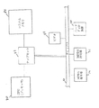
図1には、本発明による動き補償システムを含む、ビデオの復号又は伸張を行うシステムを示す。本発明のシステムは、ビデオ復号又はビデオ伸張の処理中にビデオシーケンスの時間的に圧縮されたフレーム間の動き補償を行うものである。換言すれば、本発明のシステムは、1つのビデオフレームのブロックを表す動き評価ベクトルを受け取り、ビデオ伸張中に圧縮データを復元するものである。しかしながら、本発明のシステムは、要望により種々のアプリケーションの種類を問わず動き補償を行うために用いることができる。
【0024】
図示したとおり、一実施形態のビデオ復号又はビデオ伸張のシステムは、汎用コンピュータシステム60を備えている。このビデオ復号システムは、コンピュータシステム、セットトップ(重ね置き用の)装置、テレビ又はその他の装置を含む種々のシステムの何れで構成してもよい。
【0025】
コンピュータシステム60は、これによって伸張又は復号されるべきデジタルビデオファイルを格納する媒体記憶ユニット62に接続することが好ましい。媒体記憶ユニット62は、結果的に得られる復号又は伸張されたビデオファイルも格納することができる。好ましい実施形態では、コンピュータシステム60が、圧縮されたビデオファイル又はビットストリームを受け取り、正規の圧縮されていないデジタルビデオファイルを生成する。ここでは、「圧縮されたビデオファイル」と言う用語は、特にMPEG規格を含む、動き予測技術を用いる種々のビデオ圧縮アルゴリズムの何れかによって圧縮されたビデオファイルを指す。また、「圧縮されていないデジタルビデオファイル」と言う用語は、復号又は伸張されたビデオストリームを指す。
【0026】
図示したとおり、コンピュータシステム60は、ビデオの復号又は伸張の動作を行うビデオ復号器74を含むことが好ましい。ビデオ復号器74は、MPEG復号器であることが好ましい。また、コンピュータシステム60は、MPEG符号器76を随意に含んでもよい。MPEG復号器74及びMPEG符号器76は、コンピュータシステム内のバスに結合されるアダプタカードであることが好ましいが、説明のためにコンピュータシステム60の外側に示してある。また、コンピュータシステム60は、ソフトウェア(フロッピィディスク72で表した)を含む。このソフトウェアにより、ビデオの伸張すなわち復号の動作の部分を行っても良く、また希望によりその他の処理を行うことも可能である。
【0027】
コンピュータシステム60は、1つ以上のプロセッサ、1つ以上のバス、ハードディスク装置及びメモリを含む種々の標準的な構成要素を含むことが好ましい。ここで、図2に、図1のコンピュータシステムに含まれる構成要素を図解するブロック図を示す。なお、図2は単に説明を目的としているだけであり、要望に応じてその他のコンピュータアーキテクチャを用いてもよい。同図より、コンピュータシステム60は、チップセット論理回路82を介してシステムメモリ84に接続された少なくとも1つのプロセッサ80を含む。チップセット82は、バス86へのインターフェイスのためのPCI(Peripheral Component Interconnect)ブリッジか、又は別の種類の拡張バスへのインターフェイスのための別の種類のバスブリッジを含むことが望ましい。図2において、MPEG復号器74及びMPEG符号器76は、PCIバス86に接続されて示されている。コンピュータシステム60には、ビデオ88及びハードディスク装置90のような、その他の種々の要素を含めることができる。
【0028】
前述のように、図1の好ましい実施形態では、コンピュータシステム60は、1つ又はそれ以上のデジタル記憶装置又は媒体記憶装置を含むか、又はこれに接続される。例えば、図1の実施形態では、コンピュータシステム60は、ケーブル64を通して媒体記憶ユニット62に接続されている。媒体記憶ユニット62は、伸張するべきデジタルビデオの格納又は結果的に得られる復号されたビデオデータの格納又はこれら両方のために、RAID[redundant array of inexpensive Disks(廉価ドライブ冗長アレイ)]ディスクアレイを備えるか、叉は1つ以上のCD−ROM装置もしくは1つ以上のデジタルビデオディスク(DVD)記憶ユニット、若しくはこれらの両方、又はその他の媒体を含むことが好ましい。また、コンピュータシステム60は、1つ又はそれ以上の内部RAIDアレイやCD−ROM装置を含んでも良く、1つ又はそれ以上の別個のデジタルビデオディスク(DVD)記憶ユニットを接続しても良く、或いはこれらの両方を行ってもよい。コンピュータシステム60は、要望に応じて、他の種類のデジタル又はアナログの記憶装置又は媒体を接続してもよい。
【0029】
また、圧縮されたデジタルビデオは、離れた記憶装置、離れたコンピュータシステム、衛星、又はケーブル網などの外部の情報源から受け取るようにしてもよい。このような実施形態では、コンピュータシステムは、デジタルビデオファイルを受信するために、ATM(非同期転送モード)アダプタカード、ISDN(統合サービスデジタル網)端末アダプタ又はその他のデジタルデータ受信装置のような入力装置を含むことが好ましい。デジタルビデオファイルは、アナログ形式で受信・格納し、コンピュータシステム60の外部又は内部の何れかにおいてデジタルデータに変換してもよい。
【0030】
前述のように、コンピュータシステム60のMPEG復号器74は、ビデオ復号又はビデオ伸張の機能を果たす。ビデオ復号又はビデオ伸張を行う場合、MPEG復号器74は、動きベクトルを含む時間的に圧縮されたフレームをデジタルビデオファイルとして受け取り、それらの圧縮されたフレームを動き補償技法を用いて伸張又は復号する。さらに後述するように、コンピュータシステム60のMPEG復号器74は、ページ間交差を減らしながら所望の基準ブロックの効率的アクセスを可能とするために、前に復号されたフレームをタイル形式でメモリに格納する。このようにして、MPEG復号器74は、本発明にしたがい効率良く且つ保証された性能で動き補償を行う。
【0031】
なお、ビデオデータを復号又は伸張する本システムは、希望に応じて2台以上の相互接続されたコンピュータを含んでもよい。ビデオデータを復号又は伸張する本システムは、また、セットトップ装置のような他のハードウェアを、単独で、又は汎用のプログラム可能なコンピュータと供に用いて、備えてもよい。なお、本発明に従いビデオデータを復号又は伸張するものであれば、希望により種々のシステムの何れを用いてもよい。
【0032】
図3−MPEG復号器ブロック図
ここで、図3に、本発明に従い動き補償を行うMPEG復号器74を説明するブロック図を示す。同図のように、ビデオ復号器74は、符号化又は圧縮されたデジタルビデオストリームを受け取り、圧縮されていないデジタルビデオストリームを出力する。圧縮されたデジタルビデオストリームとは、テレビ又はコンピュータシステムなどの画面上にテレビ画像又は動画などのビデオシーケンスを映し出すのに用いられる圧縮ビデオデータのビットストリームである。好ましい実施形態においては、圧縮デジタルビデオストリームは、MPEG−2圧縮アルゴリズムを用いて圧縮されるので、ビデオ復号器74は、MPEG−2復号器であることが好ましい。MPEG復号器の動作は、当業界において公知であるから、その動作の詳細(本発明の動作には不要である)は、簡単のため省略する。
【0033】
図3に示すとおり、MPEG復号器74は、逆走査ブロック104に出力を与えるように接続された可変長復号ブロック102を備え、逆走査ブロック104は、逆量子化ブロック106に出力を与えるように接続され、これが、逆DCTブロック108に出力を与えるように接続され、これが、動き補償ブロック110に出力を与えるように接続されている。動き補償ブロック110は、復号された標本を含む出力を与える。動き補償ブロック110の出力には、復号されたフレームデータを受信及び格納するフレームメモリ112が接続される。動き補償ブロック110は、フレームメモリ112の出力に接続され、動き補償の間にフレームメモリ112から基準ブロックデータを受け取る。
【0034】
図3に示すとおり、可変長復号ブロック102は、符号化されたデータ(以降、「符号化データ」のように表す)を受信し、可変長復号を行う。公知のとおり、MPEG規格の規定では、データは、可変長符号を用いて伝送できるように圧縮される。このため、可変長復号ブロック102は、前記のデータを復号してQFS[n]という出力を生成する。可変長復号ブロック102のQFS[n]出力は、逆走査ブロック104に与えられる。逆走査ブロック104は、受信したデータのジグザグな走査順(これは、ここまで適切である)を逆にし、QF[v][u]という出力を生成する。この出力QF[v][u]は、逆量子化ブロック106に与えられる。逆量子化ブロック106は、逆量子化、又はデクウオンタイズ(de-quantize)して、F[v][u]という逆量子化されたデータを生成する。逆量子化ブロック106の出力F[v][u]は、逆DCTブロック108に与えられ、この逆DCTブロック108は、逆離散コサイン変換を行い、データを周波数領域から画素領域へと戻す。逆DCTブロック108は、f[y][x]と言う出力を生成する。逆DCTブロック108の出力f[y][x]は、動き補償ブロック110に与えられる。
【0035】
逆DCTブロック108からの出力f[y][x]は、画素データの時間的に符号化されたフレームからなる。動き補償ブロック110は、動き補償技法を用いて時間的に圧縮されたフレームを伸張する。前述のように、MPEG符号化ストリームは、I、P及びBのフレームから成る。P及びBは、他のフレームに対して時間的に圧縮されている。Pフレームは、前のI又はPフレームに対して時間的に圧縮され、Bフレームは、前又は後のI又はPフレームに対して時間的に圧縮されている。フレームを時間的に圧縮する際、該フレームを目的ブロックというマクロブロックへと区分し、さらにこの圧縮方法は、符号化中のブロックに最も似たブロックを求めて近隣のフレームを探す。最も適合するブロックが見つかると、各目的ブロックは、基準フレーム内の該最も適合する基準ブロックを指し示す動きベクトルにより符号化される。また、符号化中のブロックと最も適合するブロックとの間の差を計算してMPEGストリームに転送する。
【0036】
動き補償ブロック110からの出力画素値は、フレームメモリ112に与えられる。フレームメモリ112は、このように動き補償ブロック110に接続されて、ビデオデータの1つ以上の基準フレームを格納する。これらのビデオデータの基準フレームは、P及びBフレームのような時間的に圧縮されたフレームに対して動き補償を行う際に使用される。一般に、MPEGストリームは、前に送られた基準フレームのデータに依存する時間的に圧縮されたデータの前に送られるところの符号化された基準フレームデータを含む。従って、到来するP及びBフレームのデータ等の時間的に符号化されたフレームのデータは、前に送られた基準フレームビデオデータ中の基準ブロック(それはフレームメモリ112に格納されている)を指し示すところの動きベクトルを含む。動き補償ブロック110は、到来する時間的に圧縮されたデータから得た各動きベクトルを分析し、各動きベクトルに応じてフレームメモリ112から基準ブロックを1つ取り出す。動作補正ブロック110は、取り出した基準ブロックを格納する局部メモリ即ちオンチップメモリ116を含む。次に、動き補償ブロック110は、この取り出した基準ブロックを用いて、時間的に圧縮されたデータを伸張する。
【0037】
好ましい実施形態では、フレームメモリ112は、1Mx16SDRAM(同期ダイナミックRAM) である。この例としては、韓国三星電子のKM416S1120AT−12があり、動作周波数67.5MHz、バーストサイズ4ワードである。フレームメモリ112は、データを複数のページに記憶するページメモリであることが好ましい。公知のことであるが、パージメモリは、一般に、行アドレスストローブ(RAS)と列アドレスストローブ(CAS)とを利用して、それぞれのページ内のデータをアクセスする。また公知のように、1つのページの中でデータがアクセスされると、行アドレスが共通で、待ち状態が必要でないので、メモリアクセスは迅速になる。しかし、ページミス又はページ交差が発生した場合、つまり現在アクセスされているページと異なるページ上に位置するデータが要求された場合、新たなRASとCASが必要となるので、待ち状態が必要となる。これにより、メモリアクセスの待ち時間が増大するため、システムの性能が低下する。
【0038】
本発明によれば、基準フレームの各基準ブロックが、新奇なスキュードタイル構造でフレームメモリ112に格納される。このスキュードタイルメモリ記憶構造により、フレームメモリ112から基準ブロックを取り出す時に発生するページ交差の最大数を制限する。
【0039】
図3に示すとおり、動き補償ブロック110は、時間的に圧縮されたフレーム中の受信した動きベクトルに基づいてフレームメモリ112の基準ブロックにアクセスするメモリコントローラ120を含む。さらに後述するように、メモリコントローラ120は、必要とされるページ交差の最大数を最小にするようにデータが配置された各メモリページから基準ブロックの全体を知能的にアクセスする。
【0040】
図4−スキュードタイルメモリ記憶
ここで、図4に、本発明の好ましい実施形態に従い、基準マクロブロック又は基準ブロックがフレームメモリ112にスキュードタイル構造で格納される様子を説明する図を示す。同図に示すとおり、フレームメモリ112の各ページが、各行に1つ以上のマクロブロックを格納して、フレームメモリ112に複数行のマクロブロックを格納することが好ましい。本発明によれば、基準ブロックのデータをフレームメモリ112から取り出すときのページ交差の最大数が最小となるように、隣接する行のマクロブロックを格納しているページを互いにスキューする。
【0041】
図4に示すとおり、基準フレームは、複数行のマクロブロックとして考えることができる。隣接する行のマクロブロックは、(a)〜(d)に示すようにスキューし、予測されるフィールドのマクロブロック内のページ交差すなわちページミスを減らすようにする。好ましい実施形態では、フレームメモリ112の各ページは、1行中の2つの隣接する輝度ブロックを格納し、隣接する行に格納される輝度ブロックを互いにマクロブロックの幅だけスキューして、予測されるフィールドのマクロブロック内でのページ交差の最大数を最小にする。
【0042】
図4の(a)は、1行にマクロブロックを奇数個有する、輝度ブロックの基準フィールド/フレームのマップであり、(c)は、1行にマクロブロックを偶数個有する、輝度ブロックの基準フィールド/フレームのマップである。同様に、図4の(b)は、1行にマクロブロックを奇数個有する、色差ブロックの基準フィールド/フレームのマップであり、(d)は、1行にマクロブロックを偶数個有する、色差ブロックの基準フィールド/フレームのマップである。
【0043】
図4の(a)及び(c)は、輝度ブロックが本発明のスキュードタイル構造で記憶される様子を示す。同図に示すように、好ましい実施形態では、好ましくは同じ行又は列のマクロブロックからの2つの隣接するマクロブロックからなる輝度ブロックが、SDRAMの1ページ(それは、好ましい実施形態では、256ワードから成る)を占める。図4の(b)及び(d)に示すように、1つのメモリページには、4個の隣接する色差ブロックが、好ましくは2x2の配列で格納される。このように、1つのメモリページには、4つの隣接する色差マクロブロックが、隣接する2行から2ブロックずつ格納される。
【0044】
図4の(a)及び(c)において、輝度予測ブロック又は基準ブロックは陰付きで示した。同図に示すように、輝度予測ブロックは、フレームメモリ112から取り出すのに、3回のページ交差を必要とするだけである。なお、輝度予測ブロック又は基準ブロックがフレームメモリ112の基準フレームに置かれている位置に関わらず、その輝度基準ブロックをフレームメモリ112から取り出すのに、最大3回のページ交差を必要とするだけである点が、注目される。同様に、図4の(b)及び(d)において、色差の予測ブロック又は基準ブロックは陰付きで示した。色差予測ブロック又は基準ブロックがフレームメモリ112の基準フレームに置かれている位置に関わらず、その色差基準ブロックをフレームメモリ112から取り出すのに、最大3回のページ交差を必要とするだけである。
【0045】
本発明の好ましい実施形態において、動き補償ブロック110は、フレームメモリ112から基準ブロック又は予測ブロックを読む動作を行うメモリコントローラ120を含む。フレームメモリ112からの基準ブロックの取り出しが、一回以上のページ交差を必要とする場合、メモリコントローラ120は、ページ交差又はページミスが起こる前に、即ちメモリコントローラ120がもう1つの基準ブロック部分を別のページから読み始める前に、各ページから関係する部分全体を読む。図4の例では、読み出し動作を行うメモリコントローラ120は、予測ブロック(図4の(a)乃至(c)の陰付きの領域)を、各々が異なるページに在るような3つの領域に細分して読むために十分知的である。メモリコントローラ120は、これらの細分されたブロックを1つずつ順に読む。このように、メモリコントローラ120は、最初のマクロブロック即ち最初のページから陰付きの部分を総て読み、次に、第2のマクロブロック即ち第2のページから陰付きの部分を総て読み、さらに第3のマクロブロック即ち第3のページから陰付きの部分を総て読む。
【0046】
本発明の好ましい実施形態において、基準フレームのメモリマップは、上方のフィールドが第1のバンクAに置かれ、下方のフィールドが第2のバンクBに置かれるように構成される。あるいは、基準フレーム全体が、メモリの隣接するバンクに格納される。
【0047】
図5及び6−フレームに基づく予測
ここで、図5及び6に、1フレーム内での動き補償、即ちフレームに基づく予測を示す。図5は、フレームDCTの実施形態を示す。この実施形態では、復号中のDCTブロック即ち目的ブロックの各行が、基準フレーム内部の交互のフィールドからの行に対応する。換言すれば、前述のとおり、フレームメモリ112が、1基準フレームのデータを、好ましくは奇数及び偶数の画素走査線からなる2つのフィールドとして記憶している。図5のフレームDCTの実施形態において、目的ブロック即ちDCTブロックは、図示したように両方のフィールド、即ち交互のフィールド、からの線を含む。なお、この実施形態では、ページ区切り即ちページ交差が、各フィールドに対して発生する。しかし、フィールドがそれぞれ異なるバンクに在り、且つ動きベクトルが両フィールドに対して同じであるから、ページ交差が、各バンク即ち各フィールドに対して同じ位置で発生するため、ページミスの数は、2倍にはならない。
【0048】
オンチップメモリ又は局部メモリの効率を最高にするためには、オンチップメモリ116は、大きさを最小に止め、予測ブロック即ち基準ブロックのみを読むようにすることが好ましい。従って、1つの実施形態では、オンチップメモリの効率を最高にするために、オンチップメモリ116を8x8の下位ブロックを1つだけ記憶するに足る大きさとする方が好ましい。このような実施形態では、オンチップメモリ116は、基準マクロブロックを、順次読み出される4個の8x8下位ブロックとしてフレームメモリ112から読み取る。これには、多くのページ交差が必要となるが、オンチップメモリ116の量は少なくて済む。なお、オンチップメモリ116が、8x8の下位ブロックを1個記憶するに足る大きさしかない場合、読み出される各下位ブロックに対してページ交差が必要となる点が、注目される。そこで、図5の例の場合、ページ交差の数は、Y0:3、Y1::1、Y2:+2、Y3:0、CR:3、そしてCB:+2となる。これにより、ページ交差は合計11となり、ワード読取りの総数は、6x9x5=270となる。
【0049】
チップ外のメモリ(オフチップメモリ)即ちフレームメモリのアクセス効率を最大にするためには、オンチップメモリ116は、1つのマクロブロックを完全に格納するに足る容量を持つことが好ましい。従って、マクロブロック全体をフレームメモリ112から読み出して、オンチップメモリ116に一度で渡すことができる。このように、オフチップメモリのアクセス効率を最大にするためには、即ちフレームメモリ112に対するメモリアクセス効率を最大にするためには、メモリコントローラ120が、輝度ブロック全体を読み、次いで色差ブロック全体を読むことが好ましい。輝度ブロック及び色差ブロックに対するページ交差の数は、それぞれ3であるから、合計6のページ交差が生じることになる。ワード読取りの総数は、17x9+9x9=234である。
【0050】
図6は、各DCT輝度ブロックの総ての線が1つのフィールドからの線に対応するフィールドDCTの実施形態を示す。なお、図6に示すページ区切りは、その基準ブロックの各フィールドに対するものである。フィールドがそれぞれ異なるバンクにあり、且つ動きベクトルが両フィールドに対して同じであるから、ページ交差が同じ位置で発生し、ページミスの数は2倍にはならない。
【0051】
図6の実施形態においてオンチップメモリの効率を最大にするには、メモリコントローラ120が、この場合も、一度に予測ブロックを1つだけ読み、局部メモリ即ちオンチップメモリを最小容量とすることが好ましい。従って、前述のように、この実施形態においては、オンチップメモリ116は、8x8の下位ブロックを1つ記憶するに足る容量に止めることが好ましい。所望のマクロブロックを読む場合、8x8の下位ブロックを一度に1つずつ読んでオンチップメモリ116に与える。このように、オンチップメモリ116は、8x8の下位ブロックを1つ記憶するに足る容量しか必要とされず、1つのマクロブロック全体を一度に格納する必要はない。図6の実施形態では、オンチップメモリが1x8ブロックを格納するだけで済み、フレームメモリ112から基準マクロブロックを1つ読むのに必要とされるページ交差の数は、Y0:3、Y1:+1、Y2:+2、Y3:+1、CR:3、そしてCB:+2となる。これにより、この実施形態のページ交差の総数は12となる。これは、図5とは異なるが、図5及び6に示すとおりY3が余分なページミスを招いたためである。ワード読取りの総数は、6x17x5=510となる。なお、半画素補間を行うには、両方のフィールドを読む必要がある点に注意を要する。
【0052】
オフチップメモリのアクセス効率を最大にするには、オンチップメモリ116は、1つのマクロブロックを完全に格納できる。この実施形態では、メモリコントローラ120が、1つの輝度ブロック全体を読み、次いで色差ブロック全体を読む。この実施形態は、輝度ブロック及び色差ブロックを読むのに、それぞれ3のページ交差を必要とし、合計6のページ交差が必要となる。この実施形態では、ワード読取りの総数は、17x9+9x9=234ワードである。
【0053】
【発明の効果】
本発明は、圧縮デジタルビデオストリームに動き補償を行うシステム及び方法を含む。本発明によれば、基準フレームをスキュードタイル構造に記憶することにより、データの取り出し時のページ交差又はページミスの最大数を最小にすることができる。これにより、動き補償システムの性能の改善、保証又はこれらの両方が実現される。
【0054】
本発明のシステム及び方法は以上の実施形態に関して説明したが、これは、ここに述べた特定の形式に制限するものではなく、むしろ請求項記載の本発明の原理及び範囲に無理なく含めることができるような代案、修正及び均等物を包含するためである。
【図面の簡単な説明】
【図1】 本発明に従い、基準ブロックデータを新奇なスキュードタイル構造で格納するフレームメモリを有する動き補償論理回路を含み、ビデオの復号を行うコンピュータシステムの外観図である。
【図2】 図1のコンピュータシステムを説明するブロック図
【図3】 本発明に従うMPEG復号器を示すブロック図である。
【図4】 本発明に従う新奇なスキュードタイル構造による基準ブロックの格納状態を示す図である。
【図5】 交互のフィールドからの行を含むフレームモードでDCTブロックにデータを格納する、フレームベースの予測を用いる動き補償を説明する図である。
【図6】 単一のフィールドからの行を含むフィールドモードでDCTブロックにデータを格納する、フレームベースの予測を用いる動き補償を説明する図である。[0001]
BACKGROUND OF THE INVENTION
The present invention relates generally to digital video compression, and more particularly to an MPEG decoder with motion compensation that stores macroblocks in a skewed tile structure to reduce crossing between pages during block access and improve performance.
[0002]
[Prior art]
Natural motion digital video requires large amounts of memory and data transfer bandwidth. Accordingly, video systems attempt to reduce the amount of storage capacity and transfer bandwidth required using various types of video compression algorithms. In general, there are different video compression schemes for still images and naturally moving videos (hereinafter referred to as “natural moving images”). To compress still image or single frame data using spatial redundancy within the frame, an intra-frame compression scheme is used. When compressing a large number of frames, that is, moving images using temporal redundancy between frames, an inter-frame compression method is used. The inter-frame compression method is dedicated to moving images and can be used alone or in association with the intra-frame compression method.
[0003]
For intra-frame or still image compression techniques, frequency range techniques such as discrete cosine transform (DCT) are commonly used. In intraframe compression, the frequency characteristics of an image frame are generally used in order to efficiently encode a frame by removing spatial redundancy. Examples of video data compression for still images include JPEG (Joint Photographic Experts Group) compression and RLE (Run Length Encoding). JPEG compression is a group of related standards that use Discrete Cosine Transform (DCT), which can be lossless (no degradation in image quality) and lossy (such that severe degradation cannot be perceived). is there. The JPEG compression method is originally designed for still image compression rather than video, but is also used for some moving image applications. The RLE compression method checks whether there is an overlapping pixel in one row in the bitmap, and acts to store the number of consecutive pixels that appear in an overlap rather than the data of the pixel itself.
[0004]
In contrast to still image compression algorithms, most video compression algorithms are designed to compress natural video. As described above, the video compression algorithm for moving images uses a concept called interframe compression that removes temporal redundancy between frames. In inter-frame compression, it is essential to store only the difference between successive frames in the data file. Further, the reference key frame or the entire image of the reference frame is generally stored in a medium compressed format. Consecutive frames are compared with key frames and only the difference between the key frame and each successive frame is stored. Periodically, for example, each time a new scene is displayed, a new key frame is stored, and then the comparison is started from this new reference point. The inter-frame compression ratio may be kept constant while changing the video quality. Alternatively, the inter-frame compression ratio may be changed depending on the content. In this case, if the video part being compressed contains many sudden changes in the scene from one image to another, the efficiency of this compression Becomes lower. Examples of video compression using interframe compression techniques include MPEG, DVI (Digital Video Interactive), and Indio.
[0005]
MPEG background
A compression standard called MPEG (Moving Pictures Experts Group) compression is a set of compression / decompression methods for natural video using the above-described inter-frame and intra-frame compression techniques. MPEG compression is especiallyMotion compensationThe processing is combined with the discrete cosine transform (DCT) processing, and in particular, a compression ratio exceeding 200: 1 can be obtained.
[0006]
There are two main MPEG standards, MPEG-1 and MPEG-2. In general, the MPEG-1 standard is based on blocks.Motion compensationIt relates to data reduction between fields using prediction (MCP) [which generally uses time difference pulse code modulation (DPCM)]. The MPEG-2 standard is similar to the MPEG-1 standard, but includes a number of extensions for a wider range of applications including interlaced digital video, such as high definition television (HDTV).
[0007]
Interframe compression schemes such as MPEG are based on the fact that in most video sequences, the background remains relatively stable even when operations occur in the foreground. Although the background may move, most of the consecutive frames in the video sequence are redundant.
[0008]
An MPEG stream includes three types of images called intra (I) frames, predicted (P) frames, and bi-directionally interpolated (B) frames. I, that is, an intra frame, includes video data of one entire frame, and is generally arranged every 10 to 15 frames. Intra frames serve as entry points for random access to files, and generally the compression ratio remains moderate. A predicted (P) frame is encoded in association with a past frame, ie, a previous intra frame or predicted frame. Thus, a P frame contains only changes to the previous I or P frame. In general, P frames undergo a significant amount of compression and are used as a basis for later predicted frames. Thus, both I and P frames are used as a reference for subsequent frames. Bi-directional interpolation (B) frames include a large amount of compression, and encoding requires both front and rear criteria. Bi-directional frames are not used as a reference for other frames.
[0009]
In general, with respect to frames following a reference frame, ie, P or B frames following a reference I or P frame, only a small portion of these frames differ from the corresponding portion of each reference frame. Therefore, for these frames, only the difference is captured and compressed and stored. The difference between these frames is typically generated using motion vector evaluation logic as described below.
[0010]
When an MPEG encoder receives a video file or video bitstream, it typically generates an I frame first. The MPEG encoder may compress each I frame using an intra-frame lossless compression technique. After generating the I frame, the MPEG encoder divides each frame into a grid of 16 × 16 pixel squares called macroblocks. The reason why each frame is divided into macro blocks is to perform motion evaluation / correction. The encoder is an exact match or near-accuracy between the target image or frame, ie, the frame being encoded, between the macroblock of the target image and one block in the adjacent image called the search frame. Find a good match. If the target frame is a P frame, the encoder searches in the previous I or P frame. If the target frame is B, search in the previous, subsequent, or both previous and subsequent I or P frames. If a match is found, the encoder sends out a vector motion code or motion vector. The vector motion code or motion vector contains only information about the difference between the search frame and each target image. Among the blocks of the target image, blocks that do not change with respect to the block of the reference image or I frame are ignored. In this way, the amount of data actually stored for these frames is significantly reduced.
[0011]
After generating the motion vector, the encoder encodes the change using spatial redundancy. Thus, after examining the change in the position of each macroblock, the MPEG algorithm further calculates and encodes the change between corresponding macroblocks. The encoding of the change is performed by a mathematical process called discrete cosine transform or DCT. By this process, the macroblock is divided into sub-blocks, and changes in color and brightness are obtained. Since human perception is more sensitive to changes in brightness than changes in color, the MPEG algorithm makes much effort to reduce color space rather than brightness.
[0012]
Thus, MPEG compression is based on two types of redundancy: space and time in a video sequence. Spatial redundancy is the redundancy in individual frames, and temporal redundancy is the redundancy between successive frames. Spatial compression is achieved by considering the frequency characteristics of the image frame. Each frame is divided into non-overlapping blocks, and each block is transformed by discrete cosine transform (DCT). After the converted block is converted into a “DCT domain (domain)”, each entry in the converted block is quantized with respect to one set of quantization tables. The quantization step for each item is changed in consideration of the sensitivity of the human visual system (HVS) to frequency. Since HVS is sensitive to low frequencies, high frequency items are often quantized to zero. In this way, information is lost in the step of quantizing each item, and an error is brought into the reproduced image. Run-length coding is used to send a quantized value (hereinafter referred to as “quantized value”). To further increase the compression, the blocks are scanned in zigzag order from the lower frequency item, and the non-zero quantized values are entropy encoded with zero run lengths.
[0013]
As mentioned above, most of the objects are invariant between successive image frames, and the difference between objects or blocks in successive frames is motion (due to object motion, camera motion, or both). The fact that they are their position in the frame as a result of is used for temporal compression. What is important in this relative encoding is motion estimation. In general, motion estimation is an essential processing requirement in most video compression algorithms. As already mentioned, motion estimation is the task of identifying temporal redundancy between frames of a video sequence.
[0014]
When the MPEG decoder receives the encoded stream, it performs the reverse of the above scanning. That is, the MPEG decoder performs reverse scanning to remove zigzag order, dequantizes the quantized data by inverse quantization, and restores the data from the frequency domain to the pixel area by inverse DCT. Also, the MPEG decoder uses the transmitted motion vector.Motion compensationTo regenerate a temporally compressed frame.
[0015]
When frames used as references for other frames, such as I or P frames, are received, these frames are decoded and stored in memory. When a temporally compressed or encoded frame, such as a P or B frame, is received, the previously received I or P reference frame is used for the received frame.Motion compensationI do. A temporally compressed or encoded frame is referred to as a destination frame, which is a motion vector that references a block in a previously decoded I or P reference frame (which is stored in memory). Including. The MPEG decoder examines the motion vector to determine each reference block in the reference frame, and accesses (reads) the reference block pointed to by the motion vector from the memory.
[0016]
In general, MPEG decoders include motion correction logic that includes local memory or on-chip memory. The MPEG decoder also includes an external memory for storing already decoded reference frames. This external memory is generally a page memory that stores data in a plurality of pages. As is well known, when data is accessed within the range of one page, since the row address is common, memory access is performed quickly, that is, without waiting. However, if a page miss (out-of-page) or page crossing occurs, that is, if data located on a page different from the currently accessed page is requested, a new RAS and CAS is required and therefore waiting. A state is needed. As a result, the memory access waiting time increases, and the system performance decreases.
[0017]
[Problems to be solved by the invention]
Therefore, in the MPEG decoderMotion compensationA new system and method for efficiently performing the above is desired.Motion compensationWhat is needed is a new system and method that minimizes the maximum number of memory page crossings in the retrieval of reference block data for use in. There is a further need for new systems and methods that guarantee performance characteristics.
[0018]
[Means for Solving the Problems]
The present invention is an MPEG decoding system and method for decoding frames of a video sequence. The MPEG decoder analyzes the motion vector in the encoded frame of the MPEG stream and regenerates the data encoded by the motion vector using the previously decoded reference blockMotion compensationIncludes logic circuits. The MPEG decoder stores reference block data according to a novel skewed tile structure, thereby minimizing the maximum number of page crossings required when retrieving this data from memory. The invention corrects performance and improves efficiency.
[0019]
The present invention preferably includes a computer system that includes a video decoder or MPEG decoder that receives a compressed video file or video bitstream and generates an uncompressed or decoded video stream. PMEG decoder includes local memoryMotion compensationIncludes blocks.Motion compensationAn external frame storage memory for storing data of a reference frame or a target frame is connected to the block. An MPEG encoded stream includes temporally encoded frame data that includes motion vectors. Each motion vector points to one reference block in a reference frame of video data stored in a frame storage memory (hereinafter referred to as “frame memory”).Motion compensationSystem (orMotion compensationBlock) operates to decode the target block using motion vectors to previously decoded blocks, referred to as reference blocks or search blocks.Motion compensationThe block analyzes the motion vector and retrieves each reference block from the frame memory according to the motion vector.
[0020]
The reference block is stored in external memory,Motion compensationAccessed as necessary by the logic circuit. Normal,Motion compensationThe logic circuit has any reference block in the reference frame.Motion compensationI do not know in advance about what is necessary. The memory is a page memory that stores data in one or more pages. According to the present invention, each reference block of the reference frame is stored in the memory according to a novel skewed tile structure (arrangement). This skewed tile memory storage structure limits the maximum number of page crossings that occur when retrieving a reference block from external memory.
[0021]
The frame memory preferably stores a plurality of rows of macroblocks, and each page of the frame memory stores one or more macroblocks in each row. According to the present invention, in order to minimize the maximum number of page crossings when fetching the data of the reference block from the frame memory, the pages storing macroblocks in adjacent rows are skewed with respect to each other. In the preferred embodiment, two adjacent macroblocks in one row are stored in each page of the frame memory, and the macroblocks stored in adjacent rows are skewed with respect to each other by the width of one macroblock. The maximum number of page crossings is minimized within the macroblock of the field.
[0022]
Thus, the present invention achieves improved memory access efficiency, guaranteed performance characteristics, or both.Motion compensationIs to do.
[0023]
DETAILED DESCRIPTION OF THE INVENTION
Video compression system
FIG. 1 shows the present invention.Motion compensation1 shows a system for decoding or decompressing video, including the system. The system of the present invention can be used between temporally compressed frames of a video sequence during the video decoding or video decompression process.Motion compensationIs to do. In other words, the system of the present invention receives a motion estimation vector representing a block of one video frame and decompresses the compressed data during video decompression. However, the system of the present invention can be applied to various types of applications as required.Motion compensationCan be used to
[0024]
As shown, the video decoding or decompression system of one embodiment includes a general
[0025]
[0026]
As shown, the
[0027]
[0028]
As described above, in the preferred embodiment of FIG. 1, the
[0029]
The compressed digital video may also be received from an external source such as a remote storage device, a remote computer system, a satellite, or a cable network. In such an embodiment, the computer system receives an input device, such as an ATM (Asynchronous Transfer Mode) adapter card, an ISDN (Integrated Services Digital Network) terminal adapter, or other digital data receiver to receive the digital video file. It is preferable to contain. Digital video files may be received and stored in analog form and converted to digital data either externally or internally within
[0030]
As described above, the
[0031]
It should be noted that the present system for decoding or decompressing video data may include two or more interconnected computers as desired. The present system for decoding or decompressing video data may also include other hardware such as set-top devices, either alone or in conjunction with a general purpose programmable computer. It should be noted that any of various systems may be used as desired as long as video data is decoded or expanded according to the present invention.
[0032]
Figure 3-MPEG decoder block diagram
Here, according to the present invention in FIG.Motion compensationFIG. 2 is a block diagram for explaining an
[0033]
As shown in FIG. 3, the
[0034]
As shown in FIG. 3, the variable
[0035]
The output f [y] [x] from the inverse DCT block 108 consists of a temporally encoded frame of pixel data.Motion compensationBlock 110Motion compensationDecompress temporally compressed frames using a technique. As described above, the MPEG encoded stream is composed of I, P, and B frames. P and B are temporally compressed with respect to other frames. P frames are temporally compressed with respect to previous I or P frames, and B frames are temporally compressed with respect to previous or subsequent I or P frames. When a frame is temporally compressed, the frame is divided into macroblocks called target blocks, and this compression method searches for a neighboring frame in search of a block most similar to the block being encoded. When the best matching block is found, each target block is encoded with a motion vector that points to the best matching reference block in the reference frame. Also, the difference between the block being encoded and the best matching block is calculated and transferred to the MPEG stream.
[0036]
Motion compensationThe output pixel value from block 110 is provided to frame
[0037]
In the preferred embodiment, the
[0038]
According to the present invention, each reference block of the reference frame is stored in the
[0039]
As shown in FIG.Motion compensationBlock 110 includes a memory controller 120 that accesses a reference block of
[0040]
Figure 4-Skewed tile memory storage
Here, FIG. 4 is a diagram illustrating how a reference macroblock or a reference block is stored in the
[0041]
As shown in FIG. 4, the reference frame can be considered as a macroblock of a plurality of rows. The macroblocks in adjacent rows are skewed as shown in (a)-(d) to reduce page crossings or page misses in the predicted field macroblocks. In the preferred embodiment, each page of
[0042]
4A is a luminance block reference field / frame map having an odd number of macroblocks in one row, and FIG. 4C is a luminance block reference field having an even number of macroblocks in one row. / Frame map. Similarly, FIG. 4B is a map of the reference field / frame of the chrominance block having an odd number of macroblocks in one row, and FIG. 4D is a chrominance block having an even number of macroblocks in one row. Is a reference field / frame map.
[0043]
FIGS. 4A and 4C show how luminance blocks are stored in the skewed tile structure of the present invention. As shown in the figure, in a preferred embodiment, a luminance block consisting of two adjacent macroblocks, preferably from the same row or column of macroblocks, is one page of SDRAM (in the preferred embodiment, from 256 words). Occupy). As shown in FIGS. 4B and 4D, four adjacent color difference blocks are preferably stored in a 2 × 2 array in one memory page. In this manner, four adjacent color difference macroblocks are stored in two blocks from two adjacent rows in one memory page.
[0044]
In FIGS. 4A and 4C, the luminance prediction block or the reference block is shaded. As shown in the figure, the luminance prediction block only needs three page crossings to be extracted from the
[0045]
In a preferred embodiment of the present invention,Motion compensationThe block 110 includes a memory controller 120 that performs an operation of reading a reference block or a prediction block from the
[0046]
In a preferred embodiment of the present invention, the memory map of the reference frame is configured such that the upper field is placed in the first bank A and the lower field is placed in the second bank B. Alternatively, the entire reference frame is stored in an adjacent bank of memory.
[0047]
Figures 5 and 6-Frame based prediction
Here, FIGS. 5 and 6 show that within one frame.Motion compensationI.e., frame-based prediction. FIG. 5 shows an embodiment of a frame DCT. In this embodiment, each row of the DCT block or target block being decoded corresponds to a row from an alternating field within the reference frame. In other words, as described above, the
[0048]
In order to maximize the efficiency of on-chip memory or local memory, the on-chip memory 116 is preferably kept to a minimum size and only reads the prediction or reference block. Thus, in one embodiment, in order to maximize the efficiency of the on-chip memory, it is preferred that the on-chip memory 116 be large enough to store only one 8x8 sub-block. In such an embodiment, the on-chip memory 116 reads the reference macroblock from the
[0049]
In order to maximize the access efficiency of off-chip memory (off-chip memory), that is, frame memory, the on-chip memory 116 preferably has a capacity sufficient to completely store one macroblock. Therefore, the entire macroblock can be read from the
[0050]
FIG. 6 shows an embodiment of a field DCT in which all lines of each DCT luminance block correspond to lines from one field. Note that the page breaks shown in FIG. 6 are for each field of the reference block. Since the fields are in different banks and the motion vectors are the same for both fields, page crossings occur at the same location and the number of page misses does not double.
[0051]
In order to maximize the efficiency of on-chip memory in the embodiment of FIG. 6, the memory controller 120 again reads only one prediction block at a time and minimizes local or on-chip memory. preferable. Therefore, as described above, in this embodiment, the on-chip memory 116 is preferably limited to a capacity sufficient to store one 8 × 8 lower block. When reading the desired macroblock, the 8 × 8 lower blocks are read one at a time and provided to the on-chip memory 116. Thus, the on-chip memory 116 only needs a capacity sufficient to store one 8 × 8 lower block, and does not need to store one macroblock at a time. In the embodiment of FIG. 6, the on-chip memory only needs to store 1 × 8 blocks, and the number of page crossings required to read one reference macroblock from the
[0052]
To maximize the access efficiency of off-chip memory, the on-chip memory 116 can completely store one macroblock. In this embodiment, the memory controller 120 reads one entire luminance block and then reads the entire chrominance block. This embodiment requires 3 page crossings each to read the luminance and chrominance blocks, for a total of 6 page crossings. In this embodiment, the total number of word reads is 17x9 + 9x9 = 234 words.
[0053]
【The invention's effect】
The present invention provides a compressed digital video stream.Motion compensationSystems and methods for performing According to the present invention, by storing the reference frame in the skewed tile structure, the maximum number of page crossings or page misses at the time of data retrieval can be minimized. ThisMotion compensationImprovements in system performance, guarantees or both are realized.
[0054]
Although the system and method of the present invention have been described with reference to the above embodiments, it is not intended to be limited to the specific form set forth herein, but rather to be reasonably included in the principles and scope of the claimed invention. It is intended to cover alternatives, modifications and equivalents as possible.
[Brief description of the drawings]
FIG. 1 includes a frame memory for storing reference block data in a novel skewed tile structure according to the present invention.Motion compensation1 is an external view of a computer system that includes a logic circuit and performs video decoding. FIG.
FIG. 2 is a block diagram illustrating the computer system of FIG.
FIG. 3 is a block diagram illustrating an MPEG decoder according to the present invention.
FIG. 4 is a diagram showing a storage state of a reference block having a novel skewed tile structure according to the present invention.
FIG. 5 uses frame-based prediction to store data in DCT blocks in a frame mode that includes rows from alternating fields.Motion compensationFIG.
FIG. 6 uses frame-based prediction to store data in a DCT block in a field mode that includes rows from a single field.Motion compensationFIG.
Claims (12)
少なくとも1つの前記ビデオデータであって、前記ビデオデータの画素を碁盤目状に分割した、複数のマクロブロックからなるビデオデータを記憶するために前記時間的に符号化されたPまたはBフレームを復号する手段に接続されたフレームメモリを含み、
前記フレームメモリがページメモリであり、
該ページメモリの各ページは、前記碁盤目の各行の隣接する2以上のマクロブロックを記憶し、
前記碁盤目の隣接する行のマクロブロックを記憶するページ同士は、少なくとも前記マクロブロックの幅だけページ区切りが互いにずれている、システム。 Means for receiving temporally encoded P or B frame data and decoding the temporally encoded P or B frame using previously decoded video data of an I or P frame ;
And at least one of the video data, the divided pixels of video data in a grid pattern, wherein the temporally decodes the encoded P or B-frame to store video data comprising a plurality of macroblocks A frame memory connected to the means to
The frame memory is a page memory;
Each page of the page memory stores two or more adjacent macroblocks in each row of the grid.
The page with each other for storing the crosscut of macroblocks adjacent rows, Ru least the only width macroblock pagination offset from one another imperial system.
前記時間的に符号化されたPまたはBフレームを復号する手段が、前記1つ以上の動きベクトルを分析し、及び前記1つ以上の動きベクトルに応じて前記フレームメモリから1つ以上のマクロブロックを取り出す、請求項1記載のシステム。Said temporally encoded P or B frame data, the frame memory at least one of which is stored in, include one or more motion vectors pointing to the macroblocks in the video data,
Means for decoding the temporally encoded P or B frame analyzes the one or more motion vectors and one or more macroblocks from the frame memory in response to the one or more motion vectors; The system of claim 1, wherein the system is removed.
前記時間的に符号化されたPまたはBフレームを復号する手段が、局部メモリを含み、
前記時間的に符号化されたPまたはBフレームを復号する手段が、前記1つ以上の動きベクトルに応じて前記フレームメモリから1つ以上のマクロブロックを読み出し且つ前記1つ以上のマクロブロックを前記局部メモリに格納するところのメモリコントローラーを含み、
前記メモリコントローラーが、前記第2のマクロブロックを前記第2のページから読み出す前に、前記第1のマクロブロック全体を前記第1のページから読み出す、請求項1または2記載のシステム。The frame memory stores macroblocks in at least first and second pages, stores first macroblocks in the first page, and stores second macroblocks in the second page;
The means for decoding the temporally encoded P or B frame comprises a local memory;
Means for decoding the temporally encoded P or B frame reads one or more macroblocks from the frame memory in response to the one or more motion vectors and reads the one or more macroblocks; Including a memory controller that stores in local memory,
The system of claim 1 or 2, wherein the memory controller reads the entire first macroblock from the first page before reading the second macroblock from the second page.
隣接する行のマクロブロックを記憶するページ同士は、前記マクロブロックの幅だけページ区切りが互いにずれている、請求項1〜3のいずれか1項記載のシステム。Each page of the frame memory stores two adjacent macroblocks in a row;
The system according to any one of claims 1 to 3, wherein pages that store macroblocks in adjacent rows are offset from each other by a width of the macroblock.
前記可変長復号データを受信して逆走査データを生成する逆走査ブロックと、
前記逆走査データを受信して逆量子化データを生成する逆量子化ブロックと、
前記逆量子化データを受信して時間的に符号化されたフレームデータを生成する逆DCTブロックと、
前記時間的に符号化されたP又はBフレームデータを受け取り、爾前に復号されたI又はPフレームのビデオデータを用いて、前記時間的に符号化されたPまたはBフレームを復号する手段と、及び
少なくとも1つの前記ビデオデータを記憶するために前記時間的に符号化されたPまたはBフレームを復号する手段に接続されたフレームメモリであって、前記ビデオデータの画素を碁盤目状に分割した、複数のマクロブロックからなるビデオデータを記憶するフレームメモリを含み、
前記フレームメモリがページメモリであり、
該ページメモリの各ページは、前記碁盤目の各行の隣接する2以上のマクロブロックを記憶し、
前記碁盤目の隣接する行のマクロブロックを記憶するページ同士は、少なくとも前記マクロブロックの幅だけページ区切りが互いにずれている、改善されたメモリ格納機構を備えたMPEG復号器。A variable-length decoding block that receives encoded data and generates variable-length decoded data;
A reverse scan block that receives the variable length decoded data and generates reverse scan data;
An inverse quantization block that receives the inverse scan data and generates inverse quantization data; and
An inverse DCT block that receives the inversely quantized data and generates temporally encoded frame data;
Means for receiving the temporally encoded P or B frame data and decoding the temporally encoded P or B frame using previously decoded video data of the I or P frame ; , and a frame memory the temporally connected to means for decoding the encoded P or B-frame to store at least one of said video data, dividing the pixels of the video data in a grid pattern wherein the, the frame memory you store video data comprising a plurality of macro-blocks,
The frame memory is a page memory;
Each page of the page memory stores two or more adjacent macroblocks in each row of the grid.
Pages with each other for storing the macroblocks adjacent rows of said cross-cut is, MPEG decoder comprising at least the only width macroblock page break are offset from one another, improved memory storage mechanism.
前記時間的に符号化されたPまたはBフレームを復号する手段が、前記1つ以上の動きベクトルを分析し、前記1つ以上の動きベクトルに応じて前記フレームメモリから前記1つ以上のマクロブロックを取り出す、請求項7記載のMPEG復号器。Said temporally encoded P or B frame data, the frame memory at least one of which is stored in, include one or more motion vectors pointing to the macroblocks in the video data,
Means for decoding said temporally encoded P or B frame analyzes said one or more motion vectors, and said one or more macroblocks from said frame memory in response to said one or more motion vectors The MPEG decoder according to claim 7, wherein the MPEG decoder is extracted.
前記時間的に符号化されたPまたはBフレームを復号する手段が、局部メモリを含み、
前記時間的に符号化されたPまたはBフレームを復号する手段が、前記1つ以上の動きベクトルに応じて前記フレームメモリから1つ以上のマクロブロックを読み出し且つ前記の1つ以上のマクロブロックを前記局部メモリに格納するところのメモリーコントローラーを含み、
前記メモリーコントローラーが、前記第2のマクロブロックを前記第2のページから読み出す前に、前記第1のマクロブロック全体を前記第1のページから読み出す、請求項7又は8記載のMPEG復号器。The frame memory stores macroblocks in at least first and second pages, stores first macroblocks in the first page, and stores second macroblocks in the second page;
The means for decoding the temporally encoded P or B frame comprises a local memory;
Means for decoding the temporally encoded P or B frame reads one or more macroblocks from the frame memory in response to the one or more motion vectors and reads the one or more macroblocks; Including a memory controller for storing in the local memory,
9. The MPEG decoder according to claim 7 or 8, wherein the memory controller reads the entire first macroblock from the first page before reading the second macroblock from the second page.
隣接する行のマクロブロックを記憶するページ同士は、前記マクロブロックの幅だけページ区切りが互いにずれている、請求項7〜9のいずれか1項記載のMPEG復号器。Each page of the frame memory stores two adjacent macroblocks in a row;
The MPEG decoder according to any one of claims 7 to 9, wherein pages that store macroblocks in adjacent rows are deviated from each other by a width of the macroblock.
Applications Claiming Priority (2)
| Application Number | Priority Date | Filing Date | Title |
|---|---|---|---|
| US772,442 | 1996-12-20 | ||
| US08/772,442 US6005624A (en) | 1996-12-20 | 1996-12-20 | System and method for performing motion compensation using a skewed tile storage format for improved efficiency |
Publications (2)
| Publication Number | Publication Date |
|---|---|
| JPH10294947A JPH10294947A (en) | 1998-11-04 |
| JP3966524B2 true JP3966524B2 (en) | 2007-08-29 |
Family
ID=25095079
Family Applications (1)
| Application Number | Title | Priority Date | Filing Date |
|---|---|---|---|
| JP36999497A Expired - Fee Related JP3966524B2 (en) | 1996-12-20 | 1997-12-19 | System and method for motion compensation using a skewed tile storage format for improved efficiency |
Country Status (4)
| Country | Link |
|---|---|
| US (1) | US6005624A (en) |
| EP (1) | EP0849953B1 (en) |
| JP (1) | JP3966524B2 (en) |
| DE (1) | DE69735402T2 (en) |
Families Citing this family (59)
| Publication number | Priority date | Publication date | Assignee | Title |
|---|---|---|---|---|
| US6215822B1 (en) | 1997-12-30 | 2001-04-10 | Sony Corporation | Motion compensated digital video decoding and buffer memory addressing therefor |
| AU9388298A (en) * | 1997-09-19 | 1999-04-12 | Sony Electronics Inc. | Motion compensated digital video decoding with buffered picture storage memory map |
| US6088047A (en) * | 1997-12-30 | 2000-07-11 | Sony Corporation | Motion compensated digital video decoding with buffered picture storage memory map |
| KR19990060797A (en) * | 1997-12-31 | 1999-07-26 | 구자홍 | Memory allocation method of decoded image data and its device |
| FR2787669B1 (en) * | 1998-12-22 | 2001-03-02 | Thomson Multimedia Sa | ADDRESSING METHOD FOR STORING IMAGE BLOCKS |
| WO2000059218A1 (en) * | 1999-03-30 | 2000-10-05 | Sony Electronics Inc. | Digital video decoding, buffering and frame-rate converting method and apparatus |
| US7039241B1 (en) * | 2000-08-11 | 2006-05-02 | Ati Technologies, Inc. | Method and apparatus for compression and decompression of color data |
| US7602847B1 (en) * | 2001-03-27 | 2009-10-13 | Vixs Systems, Inc. | Device and method for compression of a video stream |
| US20070053428A1 (en) * | 2001-03-30 | 2007-03-08 | Vixs Systems, Inc. | Managed degradation of a video stream |
| US8107524B2 (en) * | 2001-03-30 | 2012-01-31 | Vixs Systems, Inc. | Adaptive bandwidth footprint matching for multiple compressed video streams in a fixed bandwidth network |
| TW515952B (en) * | 2001-04-23 | 2003-01-01 | Mediatek Inc | Memory access method |
| US7218842B1 (en) | 2001-07-25 | 2007-05-15 | Cisco Technology, Inc. | Efficient methods of performing motion compensation based decoding and recoding of compressed video bitstreams |
| US6959348B1 (en) * | 2001-07-30 | 2005-10-25 | Vixs Systems, Inc. | Method and system for accessing data |
| US7675972B1 (en) | 2001-07-30 | 2010-03-09 | Vixs Systems, Inc. | System and method for multiple channel video transcoding |
| US6996178B1 (en) * | 2001-08-27 | 2006-02-07 | Cisco Technology, Inc. | Look ahead motion compensation |
| US7139330B1 (en) | 2001-10-31 | 2006-11-21 | Vixs Systems, Inc. | System for signal mixing and method thereof |
| US7596127B1 (en) | 2001-10-31 | 2009-09-29 | Vixs Systems, Inc. | System for allocating data in a communications system and method thereof |
| US7106715B1 (en) | 2001-11-16 | 2006-09-12 | Vixs Systems, Inc. | System for providing data to multiple devices and method thereof |
| US7403564B2 (en) * | 2001-11-21 | 2008-07-22 | Vixs Systems, Inc. | System and method for multiple channel video transcoding |
| US7356079B2 (en) * | 2001-11-21 | 2008-04-08 | Vixs Systems Inc. | Method and system for rate control during video transcoding |
| US7165180B1 (en) | 2001-11-27 | 2007-01-16 | Vixs Systems, Inc. | Monolithic semiconductor device for preventing external access to an encryption key |
| US7310679B1 (en) | 2002-04-29 | 2007-12-18 | Vixs Systems Inc. | Method and system for transmitting video content while preventing other transmissions in a contention-based network |
| US7120253B2 (en) * | 2002-05-02 | 2006-10-10 | Vixs Systems, Inc. | Method and system for protecting video data |
| SG111087A1 (en) * | 2002-10-03 | 2005-05-30 | St Microelectronics Asia | Cache memory system |
| US20040141555A1 (en) * | 2003-01-16 | 2004-07-22 | Rault Patrick M. | Method of motion vector prediction and system thereof |
| US7408989B2 (en) * | 2003-01-16 | 2008-08-05 | Vix5 Systems Inc | Method of video encoding using windows and system thereof |
| US7606305B1 (en) | 2003-02-24 | 2009-10-20 | Vixs Systems, Inc. | Method and system for transcoding video data |
| US7133452B1 (en) | 2003-02-24 | 2006-11-07 | Vixs Systems, Inc. | Method and system for transcoding video data |
| US7327784B2 (en) * | 2003-02-24 | 2008-02-05 | Vixs Systems, Inc. | Method and system for transcoding video data |
| US7130350B1 (en) | 2003-02-28 | 2006-10-31 | Vixs Systems, Inc. | Method and system for encoding and decoding data in a video stream |
| EP1602240A2 (en) * | 2003-03-03 | 2005-12-07 | Mobilygen Corporation | Array arrangement for memory words and combination of video prediction data for an effective memory access |
| US7739105B2 (en) * | 2003-06-13 | 2010-06-15 | Vixs Systems, Inc. | System and method for processing audio frames |
| US7277101B2 (en) | 2003-09-29 | 2007-10-02 | Vixs Systems Inc | Method and system for scaling images |
| US7668396B2 (en) * | 2003-09-29 | 2010-02-23 | Vixs Systems, Inc. | Method and system for noise reduction in an image |
| GB0323284D0 (en) | 2003-10-04 | 2003-11-05 | Koninkl Philips Electronics Nv | Method and apparatus for processing image data |
| US7406598B2 (en) * | 2004-02-17 | 2008-07-29 | Vixs Systems Inc. | Method and system for secure content distribution |
| US7480335B2 (en) * | 2004-05-21 | 2009-01-20 | Broadcom Corporation | Video decoder for decoding macroblock adaptive field/frame coded video data with spatial prediction |
| US7421048B2 (en) * | 2005-01-20 | 2008-09-02 | Vixs Systems, Inc. | System and method for multimedia delivery in a wireless environment |
| US7609766B2 (en) * | 2005-02-08 | 2009-10-27 | Vixs Systems, Inc. | System of intra-picture complexity preprocessing |
| US8949920B2 (en) * | 2005-03-17 | 2015-02-03 | Vixs Systems Inc. | System and method for storage device emulation in a multimedia processing system |
| US7400869B2 (en) * | 2005-03-22 | 2008-07-15 | Vixs Systems Inc. | System and method for adaptive DC offset compensation in wireless transmissions |
| US7660354B2 (en) * | 2005-05-11 | 2010-02-09 | Fang Shi | Temporal error concealment for bi-directionally predicted frames |
| US7707485B2 (en) | 2005-09-28 | 2010-04-27 | Vixs Systems, Inc. | System and method for dynamic transrating based on content |
| US20070112826A1 (en) * | 2005-11-10 | 2007-05-17 | Vixs Systems, Inc. | Multimedia transcoding based on remaining storage capacity |
| US8131995B2 (en) * | 2006-01-24 | 2012-03-06 | Vixs Systems, Inc. | Processing feature revocation and reinvocation |
| US20070242746A1 (en) * | 2006-04-12 | 2007-10-18 | Takehiro Kishimoto | Video signal processing device |
| US7768520B2 (en) * | 2006-05-03 | 2010-08-03 | Ittiam Systems (P) Ltd. | Hierarchical tiling of data for efficient data access in high performance video applications |
| US20080137745A1 (en) * | 2006-12-12 | 2008-06-12 | Yu-Jen Lai | Method and device for processing video data |
| DE102007005866B4 (en) * | 2007-02-06 | 2021-11-04 | Intel Deutschland Gmbh | Arrangement, method and computer program product for displaying a sequence of digital images |
| US8090718B2 (en) * | 2008-04-17 | 2012-01-03 | Research In Motion Limited | Methods and apparatus for improving backward seek performance for multimedia files |
| US8477146B2 (en) | 2008-07-29 | 2013-07-02 | Marvell World Trade Ltd. | Processing rasterized data |
| US10085016B1 (en) | 2013-01-18 | 2018-09-25 | Ovics | Video prediction cache indexing systems and methods |
| US9305325B2 (en) | 2013-09-25 | 2016-04-05 | Apple Inc. | Neighbor context caching in block processing pipelines |
| US9270999B2 (en) | 2013-09-25 | 2016-02-23 | Apple Inc. | Delayed chroma processing in block processing pipelines |
| US9299122B2 (en) | 2013-09-25 | 2016-03-29 | Apple Inc. | Neighbor context processing in block processing pipelines |
| US9215472B2 (en) | 2013-09-27 | 2015-12-15 | Apple Inc. | Parallel hardware and software block processing pipelines |
| US9218639B2 (en) | 2013-09-27 | 2015-12-22 | Apple Inc. | Processing order in block processing pipelines |
| US9571846B2 (en) | 2013-09-27 | 2017-02-14 | Apple Inc. | Data storage and access in block processing pipelines |
| US9807410B2 (en) | 2014-07-02 | 2017-10-31 | Apple Inc. | Late-stage mode conversions in pipelined video encoders |
Family Cites Families (12)
| Publication number | Priority date | Publication date | Assignee | Title |
|---|---|---|---|---|
| US5136717A (en) * | 1988-11-23 | 1992-08-04 | Flavors Technology Inc. | Realtime systolic, multiple-instruction, single-data parallel computer system |
| CA2062200A1 (en) * | 1991-03-15 | 1992-09-16 | Stephen C. Purcell | Decompression processor for video applications |
| JPH0620050A (en) * | 1992-07-03 | 1994-01-28 | Matsushita Electric Ind Co Ltd | Dynamic image signal decoding device and estimated motion vector calculation method |
| US5278647A (en) * | 1992-08-05 | 1994-01-11 | At&T Bell Laboratories | Video decoder using adaptive macroblock leak signals |
| NL9201640A (en) * | 1992-09-22 | 1994-04-18 | Nederland Ptt | System comprising at least one encoder for encoding a digital signal and at least one decoder for decoding a digital signal, and an encoder and decoder for use in the system according to the invention. |
| KR960010487B1 (en) * | 1993-08-18 | 1996-08-01 | 엘지전자 주식회사 | Progressive video format converter using motion vector |
| WO1995009421A1 (en) * | 1993-09-29 | 1995-04-06 | Sony Corporation | Method and device for reproducing data |
| DE69522861T2 (en) * | 1994-06-30 | 2002-04-11 | Koninkl Philips Electronics Nv | Method and device for code conversion of coded data stream |
| TW245871B (en) * | 1994-08-15 | 1995-04-21 | Gen Instrument Corp | Method and apparatus for efficient addressing of dram in a video decompression processor |
| US5784011A (en) * | 1996-06-14 | 1998-07-21 | Lsi Logic Corporation | Multiplier circuit for performing inverse quantization arithmetic |
| US5781239A (en) * | 1996-06-20 | 1998-07-14 | Lsi Logic Corporation | System and method for performing an optimized inverse discrete cosine transform with improved efficiency |
| US5883679A (en) * | 1997-02-20 | 1999-03-16 | C-Cube Microsystems, Inc. | Scanning scheme for images stored in dynamic random access memory |
-
1996
- 1996-12-20 US US08/772,442 patent/US6005624A/en not_active Expired - Lifetime
-
1997
- 1997-12-16 EP EP97122130A patent/EP0849953B1/en not_active Expired - Lifetime
- 1997-12-16 DE DE69735402T patent/DE69735402T2/en not_active Expired - Lifetime
- 1997-12-19 JP JP36999497A patent/JP3966524B2/en not_active Expired - Fee Related
Also Published As
| Publication number | Publication date |
|---|---|
| US6005624A (en) | 1999-12-21 |
| EP0849953B1 (en) | 2006-03-08 |
| EP0849953A3 (en) | 2000-10-25 |
| JPH10294947A (en) | 1998-11-04 |
| DE69735402D1 (en) | 2006-05-04 |
| DE69735402T2 (en) | 2006-10-19 |
| EP0849953A2 (en) | 1998-06-24 |
Similar Documents
| Publication | Publication Date | Title |
|---|---|---|
| JP3966524B2 (en) | System and method for motion compensation using a skewed tile storage format for improved efficiency | |
| US5912676A (en) | MPEG decoder frame memory interface which is reconfigurable for different frame store architectures | |
| US5818533A (en) | Method and apparatus for decoding B frames in video codecs with minimal memory | |
| US5883823A (en) | System and method of a fast inverse discrete cosine transform and video compression/decompression systems employing the same | |
| EP0843485B1 (en) | Video decoder with unified memory | |
| US6301304B1 (en) | Architecture and method for inverse quantization of discrete cosine transform coefficients in MPEG decoders | |
| US6198772B1 (en) | Motion estimation processor for a digital video encoder | |
| US6404817B1 (en) | MPEG video decoder having robust error detection and concealment | |
| JP4082525B2 (en) | System and method for performing motion estimation with improved efficiency in the DCT domain | |
| JP3462208B2 (en) | Video signal decompressor for independently compressed even and odd field data | |
| JP3395166B2 (en) | Integrated video decoding system, frame buffer, encoded stream processing method, frame buffer allocation method, and storage medium | |
| US6694342B1 (en) | Scaled forward and inverse discrete cosine transform and video compression/decompression systems employing the same | |
| US6072548A (en) | Video decoder dynamic memory allocation system and method allowing variable decoded image size | |
| KR20000057375A (en) | Parallel decoding of interleaved data streams within an mpeg decoder | |
| US5781239A (en) | System and method for performing an optimized inverse discrete cosine transform with improved efficiency | |
| US5903282A (en) | Video decoder dynamic memory allocation system and method with an efficient freeze mode | |
| US5926227A (en) | Video decoder dynamic memory allocation system and method with error recovery | |
| US5748240A (en) | Optimal array addressing control structure comprising an I-frame only video encoder and a frame difference unit which includes an address counter for addressing memory addresses | |
| JPH1098723A (en) | Mpeg video decoder circuit and method for actualizing reduction of memory | |
| US6163576A (en) | Video encoder having reduced memory bandwidth requirements | |
| JPH08116539A (en) | Dynamic image coder and dynamic image coding method | |
| JPH10271516A (en) | Compression coder, coding method, decoder and decoding method | |
| JP2898413B2 (en) | Method for decoding and encoding compressed video data streams with reduced memory requirements | |
| JP2002112268A (en) | Compressed image data decoding apparatus | |
| JP2000165875A (en) | Moving image resolution converting and encoding/ decoding device with a little memory capacity |
Legal Events
| Date | Code | Title | Description |
|---|---|---|---|
| A621 | Written request for application examination |
Free format text: JAPANESE INTERMEDIATE CODE: A621 Effective date: 20041216 |
|
| A131 | Notification of reasons for refusal |
Free format text: JAPANESE INTERMEDIATE CODE: A131 Effective date: 20060814 |
|
| A521 | Written amendment |
Free format text: JAPANESE INTERMEDIATE CODE: A523 Effective date: 20061114 |
|
| A131 | Notification of reasons for refusal |
Free format text: JAPANESE INTERMEDIATE CODE: A131 Effective date: 20061207 |
|
| A524 | Written submission of copy of amendment under section 19 (pct) |
Free format text: JAPANESE INTERMEDIATE CODE: A524 Effective date: 20070222 |
|
| TRDD | Decision of grant or rejection written | ||
| A01 | Written decision to grant a patent or to grant a registration (utility model) |
Free format text: JAPANESE INTERMEDIATE CODE: A01 Effective date: 20070502 |
|
| A61 | First payment of annual fees (during grant procedure) |
Free format text: JAPANESE INTERMEDIATE CODE: A61 Effective date: 20070528 |
|
| R150 | Certificate of patent or registration of utility model |
Free format text: JAPANESE INTERMEDIATE CODE: R150 |
|
| FPAY | Renewal fee payment (event date is renewal date of database) |
Free format text: PAYMENT UNTIL: 20110608 Year of fee payment: 4 |
|
| FPAY | Renewal fee payment (event date is renewal date of database) |
Free format text: PAYMENT UNTIL: 20110608 Year of fee payment: 4 |
|
| FPAY | Renewal fee payment (event date is renewal date of database) |
Free format text: PAYMENT UNTIL: 20120608 Year of fee payment: 5 |
|
| FPAY | Renewal fee payment (event date is renewal date of database) |
Free format text: PAYMENT UNTIL: 20120608 Year of fee payment: 5 |
|
| FPAY | Renewal fee payment (event date is renewal date of database) |
Free format text: PAYMENT UNTIL: 20130608 Year of fee payment: 6 |
|
| R250 | Receipt of annual fees |
Free format text: JAPANESE INTERMEDIATE CODE: R250 |
|
| R250 | Receipt of annual fees |
Free format text: JAPANESE INTERMEDIATE CODE: R250 |
|
| S111 | Request for change of ownership or part of ownership |
Free format text: JAPANESE INTERMEDIATE CODE: R313113 |
|
| S531 | Written request for registration of change of domicile |
Free format text: JAPANESE INTERMEDIATE CODE: R313531 |
|
| S533 | Written request for registration of change of name |
Free format text: JAPANESE INTERMEDIATE CODE: R313533 |
|
| R350 | Written notification of registration of transfer |
Free format text: JAPANESE INTERMEDIATE CODE: R350 |
|
| R250 | Receipt of annual fees |
Free format text: JAPANESE INTERMEDIATE CODE: R250 |
|
| LAPS | Cancellation because of no payment of annual fees |