JP3965591B2 - Percussion wire line sampling device - Google Patents
Percussion wire line sampling device Download PDFInfo
- Publication number
- JP3965591B2 JP3965591B2 JP23337397A JP23337397A JP3965591B2 JP 3965591 B2 JP3965591 B2 JP 3965591B2 JP 23337397 A JP23337397 A JP 23337397A JP 23337397 A JP23337397 A JP 23337397A JP 3965591 B2 JP3965591 B2 JP 3965591B2
- Authority
- JP
- Japan
- Prior art keywords
- spring
- tip
- tube
- core
- guide
- Prior art date
- Legal status (The legal status is an assumption and is not a legal conclusion. Google has not performed a legal analysis and makes no representation as to the accuracy of the status listed.)
- Expired - Lifetime
Links
Images


Landscapes
- Investigation Of Foundation Soil And Reinforcement Of Foundation Soil By Compacting Or Drainage (AREA)
Description
【0001】
【発明の属する技術分野】
本発明は、特に地質調査において地質試料(以下、コアと称する)を採取する際に用いられるパーカッションワイヤラインサンプリング装置に関する。
【0002】
【従来の技術】
従来一般のパーカッションワイヤラインサンプリング装置は、ロータリパーカッションドリルのアウタチューブに内蔵されるワイヤラインサンプラと、このワイヤラインサンプラをアウタチューブ内に搬入及び搬出するオーバショットアセンブリとを備えてなるが、このような一般的なパーカッションワイヤラインサンプリング装置により、特にN値(地盤の軟硬を示す値で、この値が低い程地盤は軟らかい)が30以下の軟弱地盤をサンプリングする場合は、循環水の影響により採取したコアが流出し易いため、必ずしも適切なサンプリングを行えるとは限らない。
【0003】
そこで、特に乱さない試料、すなわちN値が0〜4のシルト、粘性土及び有機質土等を採取する場合は、例えばデニソンサンプラ、ピッチャサンプラに代表される二重管サンプラや、アウタチューブに内蔵されたインナチューブ内にスプリットチューブが装備されたトリプルコアチューブ等のサンプリング装置を用いるようにしている。
【0004】
【発明が解決しようとする課題】
しかしながら、上述した二重管サンプラやトリプルコアチューブは、パーカッションワイヤラインを適用していないため、掘削速度が遅くコアの採取率が低い上、コア詰りの発生頻度も高く、また構造上耐打撃強度が弱いため、破損及び故障の頻度が高かった。さらに、部品点数が多く構造が複雑であるため、製造コストも高く、メンテナンス性も低下していた。一方、サンプラの摺動部分(ピストン等)における錆び付きに対して何ら対応策が講じられていないためスライド不良が発生し、これによっても採取率の低下が助長されていた。
【0005】
本発明は、上記の課題を解決し得るものであって、その目的は、パーカッションワイヤラインにおいて、コアの採取率、地盤の掘削速度を充分に確保しつつコア詰りを解消し、N値が30以下の地盤も好適にサンプリングすることを可能にすると共に、サンプリング作業の際にロッドの抜管・再挿入作業を不要にして作業効率を向上させ、さらに部品点数を低下させて製品の廉価化及びメンテナンス性の向上をも実現できるパーカッションワイヤラインのサンプリング装置を提供することにある。
【0006】
【課題を解決するための手段】
上記目的を達成するため、本発明のパーカッションワイヤラインのサンプリング装置は、円筒状のシリンダチューブと、このシリンダチューブの先端に取り付けられたシリンダリングと、前記シリンダチューブとシリンダリングとに内嵌されその内部にコアが導入されるコアチューブとからなり、ロータリパーカッションドリルのアウタチューブに内蔵されるワイヤラインサンプラと;アウタチューブの先端に螺合されるコアビットと;ガイドシャフトに内嵌されると共に、シリンダチューブの後端に連結された断面円形のスプリングガイドに外嵌され、アウタチューブ内に同心的に配設されてワイヤラインサンプラを先端側へ向けて付勢するスプリングと;先端がガイドシャフトに連結され、且つ後端がワイヤラインサンプラをアウタチューブ内に搬入及び搬出するオーバショットアセンブリに連結されるコアバレルヘッドと、を備え;スプリングガイドの先端には、スプリングガイドの内径より縮径された段部が形成され;ガイドシャフトは、スプリングガイドの段部内を挿通可能な挿通部と、この挿通部から拡径されてスプリングが外嵌可能な中間部と、この中間部から拡径されてコアバレルヘッド先端に螺合可能な結合部とからなり;ガイドシャフトの挿通部は、スプリングガイドの先端から突出した上でワッシャを介してナットが螺合され、スプリングは、ガイドシャフトの中間部と結合部との境界段部と、スプリングガイドの段部との間で伸縮可能とされ;スプリングが伸びた状態では、コアビットの先端からシリンダリングの先端が突出した状態となり、スプリングが縮んだ状態では、コアビットの先端とシリンダリングの先端とが一致した状態となるように構成したことを特徴としている。
【0007】
上記のようなパーカッションワイヤラインのサンプリング装置において、スプリングガイドとガイドシャフトとに、ガス軟窒化処理を施すと共に、四三酸化鉄で表面処理を施したものとすることが好ましい。
【0008】
【発明の実施の形態】
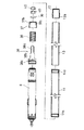
以下、本発明の実施の形態を図面を参照して詳細に説明する。図1ないし図9は、本発明の実施の一形態を示す図である。これらの図において、符号1はロータリパーカッションドリルであり、このロータリパーカッションドリル1は、アウタチューブ2内にインナチューブ3が内蔵されてなっている。
【0009】
アウタチューブ2は、図3にその詳細を示すように、円筒状をなし、その先端側(図3において右側)には、図4にその詳細を示すコアビット4が螺合される。このコアビット4は、先端側に複数(この例では6つ)の刃4aが断面円周方向に等間隔で形成されており、図示しないドリルロッド及びアウタチューブ2の回転、給進及び打撃のそれぞれに伴って同一に動作するようになっている。
【0010】
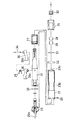
一方、インナチューブ3は、図5及び図6にその詳細を示すように、アウタチューブ2の前方位置において同心的に配設されたサンプラ5と、同後方位置において当該サンプラ5に螺合して連結されたコアバレルヘッド6とを備えてなる。サンプラ5は、円筒状をしたシリンダチューブ11と、このシリンダチューブ11の先端に取り付けられたシリンダリング12と、これらシリンダチューブ11及びシリンダリング12内に内嵌されその内部にコアが導入されるコアチューブ13とからなる。
【0011】
さらに詳しくは、シリンダチューブ11とシリンダリング12とは、シリンダチューブ11の前方内面に形成された雌螺子11aにシリンダリング12外面に形成された雄螺子12aが螺合することにより一体化され、これらは特に硬度の高い材料からなっており、シリンダリング12によってシリンダチューブ11の先端が保護されて耐摩耗性が確保される。また、コアチューブ13は、主に鋼製であるが、サンプリングされる地盤の地質に応じて例えば塩化ビニール製のものも使用できる。
【0012】
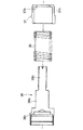
一方、図7及び図8にその詳細を示すコアバレルヘッド6は、以下の構成からなる。すなわち、符号22で示すメーンシャフトは、アウタチューブ2に対して同心的に配設されるスプリングケース23に内嵌され、このスプリングケース23より前方位置においてはベアリングケース24が外嵌されている一方、後端部にはスピア25が連結され、さらに略中央部においてはラッチ26が取り付けられている。
【0013】
前記スプリングケース23は、その前方位置においてメーンシャフト22との間でスプリング27を把持すると共に、その後端部が符号28で示すボルトによりスピア25に一体的に結合される。前記スプリング27は、符号22aで示すメーンシャフト22の係止段部と、スプリングケース23先端の内壁面側に向けて形成された係止段部24aとにより規制され、この範囲内で伸縮可能となっている。
【0014】
また、ベアリングケース24は、メーンシャフト22との間でベアリング29を把持すると共に、その前方位置においてメーンシャフト22先端に螺合する袋ナット30が嵌合され、その後方位置において軸受け31が嵌合される。なお、この軸受け31は、メーンシャフト22とベアリングケース24との間に配設したハンガボディ32により移動規制されている。
【0015】
さらに、スピア25は、その先端側がメーンシャフト22後端側の中空部22b内にOリング33を介して嵌入され、また後端においては図示しないオーバショットアセンブリに係合する係合部25aが設けられている。また、ラッチ26は、枢軸34により拡縮自在に枢着され、通常はラッチスプリング35にて開拡方向に付勢されている。
【0016】
この開拡状態において、ラッチ26に形成されたラッチ爪26aの先端外側は、スプリングケース23に穿設されたスリット24cより外出してアウタチューブ2の内面に当接している。
【0017】
そして、オーバショットアセンブリをスピア25の係合部25aに係合させて吊り上げると、スピア25に結合されたスプリングケース23が上方に移動し、この際スプリング27がその弾性により縮むと共に、当該スプリングケース23によりラッチ26が縮径される。すなわち、ラッチ爪26aは、後方が開拡する扇形に設けられており、スプリングケース23の移動により、ラッチスプリング35が収縮しつつスリット24cの前端面で縮径されるものである。
【0018】
このようなサンプラ5とコアバレルヘッド6との間には、前記スプリング27とは別のスプリング36が介装されている。さらに詳しくは、前記シリンダチューブ11の後端には、断面円形をしたスプリングガイド37が取り付けられ、これらはシリンダチューブ11後端内面に形成した雌螺子11bとスプリングガイド37前端外面に形成した雄螺子37aとが螺合することにより一体化しており、スプリングガイド37の前端は、当該スプリングガイド37内径より縮径された段部37bが形成されている。
【0019】
一方、前記コアバレルヘッド6の前端にはガイドシャフト38が螺合され、このガイドシャフト38は、その前方に前記スプリングガイド37の段部37b内を挿通可能な挿通部38aと、この挿通部38aより拡径されてスプリング36が外嵌可能な中間部38bと、この中間部38bより拡径されて前記ベアリングケース24前端に螺合可能な結合部38cとからなる。特に、このガイドシャフト38と前記スプリングガイド37とには、ガス軟窒化処理を施すと共に、四三酸化鉄により表面処理が施されている。
【0020】
そして、これらスプリング36、スプリングガイド37及びガイドシャフト38は、以下の通りに結合されている。すなわち、ガイドシャフト38の中間部38bにスプリング36が外嵌され、さらにこのスプリング36にスプリングガイド37が外嵌され、したがってスプリング36は、中間部38b外面とスプリングガイド37内面との間に介装された状態となっている。
【0021】
ガイドシャフト38の挿通部38aは、スプリングガイド37の前端から突出した上で符号39示すワッシャを介してナット40が螺合される。これにより、スプリングガイド37は、ガイドシャフト38の中間部38bと結合部38cとの境界段部と、ナット40の下端面との間で移動範囲が規制され、したがってスプリング36は、前記境界段部とスプリングガイド37の段部37bとの間で伸縮可能となっている。
【0022】
ここで、ガイドシャフト38はシリンダチューブ11に螺合されているから、スプリング36が伸びた状態では、図1に示すようにコアビット4の先端からシリンダリング12の先端が突出した状態となり、またスプリング36が縮んだ状態では、図2に示すようにコアビット4の先端とシリンダリング12の先端とが一致した状態となる。
【0023】
次に、上述したロータリパーカッションドリル1の作用について説明する。図1に示すようなセット状態(すなわち、スプリング36が伸びた状態)から、ドリルロッドに回転と共に適宜給進及び打撃を与えて地盤を掘削する。この際は、通常のパーカッションワイヤラインと同様の掘削速度が実現される。
【0024】
そして、ドリルロッドの給進に伴い、コアチューブ13内にはコアが導入されていく。この際、スプリング36の弾性により、コアビット4の先端からのシリンダリング12の突出長さが適宜調整され、循環水によるコアの流出が防止されつつサンプリングが行われていく。また、ガイドシャフト38とスプリングガイド37とには、ガス軟窒化処理が施されると共に四三酸化鉄により表面処理が施されているから、これらの摺動に伴う摩耗による心ずれが防止されると共に、錆び付きも防止され、常に良好な状態でサンプリングが行われる。
【0025】
次いで、コアチューブ13内にコアが一杯に詰め込まれると、図示しないオーバショットアセンブリをスピア25の係合部25aに係合させて吊り上げることによりサンプラ5を回収する。その後、再びサンプリングを行う際は、アウタチューブ2は地盤から抜管する必要はなく、シリンダチューブ11とスプリングガイド37との螺合を解除してサンプラ5のみを取り替えれば良い。このようなサンプラ5の取り替えは、地質の変化(例えば、軟弱地盤から固結地盤へのサンプリング作業の移行)に対しても同様に行えばよい。
【0026】
このように、本発明のサンプリング装置によれば、パーカッションワイヤラインの利点であるコアの高採取率、高掘削速度を充分に確保しつつ、スプリング36によりシリンダチューブ11及びコアチューブ13がコアビット4先端から突出され、これによりN値が30以下のような軟弱地盤のサンプリングを的確に行うことができると共に、コア詰りも解消される。
【0027】
さらに、アウタチューブ2を度々抜管・再挿入せずにサンプリング装置のみを容易に交換することができるので作業性が著しく向上されると共に、簡素な構成で部品点数が減少されているから、メンテナンス性も向上され、装置全体の廉価化を実現することができる。その上、ガイドシャフト38とスプリングガイド37とに、ガス軟窒化処理を施すと共に四三酸化鉄により表面処理を施したことから、これらの錆び付きが防止されると共に摩耗が防止され、よってサンプラ5のスライド不良が防止されて常に良好な状態でサンプリングを行うことが可能となる。
【0028】
【発明の効果】
以上の説明から明らかなように、本発明のパーカッションワイヤラインサンプリング装置によれば、パーカッションワイヤラインにおける軟弱地盤のサンプリングにおいても、コアの採取率、掘削速度を充分に確保しつつ的確にサンプリングを行うことができると共に、コア詰りも解消することができる。また、アウタチューブを度々抜管・再挿入せずにサンプリング装置のみを容易に交換することができるので作業性が著しく向上され、さらに簡素な構成でメンテナンス性の向上及び部品点数の減少と装置全体の廉価化を実現することができる。
【0029】
また、ガイドシャフトとスプリングガイドの錆び付きを防止して作動不良の防止を実現することができると共に、摩耗も低下させてワイヤラインサンプラの心ずれを防止することができる。
【図面の簡単な説明】
【図1】 本実施の形態で説明したロータリパーカッションドリルのセット時の状態を示す断面図である。
【図2】 同作動時の状態を示す断面図である。
【図3】 本実施の形態で説明したアウタチューブを示す断面図である。
【図4】 同コアビットを示す図であり、同図(a)は断面図、同図(b)は正面図である。
【図5】 同インナーチューブを示す部分断面図である。
【図6】 図5におけるサンプラの分解断面図である。
【図7】 図5及び図6のコアバレルヘッドの断面図である。
【図8】 図8のコアバレルヘッドの分解断面図である。
【図9】 図5及び図6のスプリング、スプリングガイド及びガイドシャフトを示す詳細図である。
【符号の説明】
1 ロータリパーカッションドリル
2 アウタチューブ
5 (ワイヤライン)サンプラ
6 コアバレルヘッド
36 スプリング
37 スプリングガイド
38 ガイドシャフト[0001]
BACKGROUND OF THE INVENTION
The present invention relates to a percussion wire line sampling apparatus used when collecting a geological sample (hereinafter referred to as a core) in a geological survey.
[0002]
[Prior art]
A conventional general percussion wireline sampling apparatus includes a wireline sampler built in an outer tube of a rotary percussion drill, and an overshot assembly that carries the wireline sampler into and out of the outer tube. When sampling soft ground with an N value (a value indicating the softness of the ground, the lower the value, the softer the ground), with a general percussion wire line sampling device, Since the collected core tends to flow out, appropriate sampling is not always possible.
[0003]
Therefore, when collecting samples that are not particularly disturbed, that is, silt, cohesive soil, organic soil, etc. having an N value of 0 to 4, for example, a double tube sampler represented by a Denison sampler or a pitcher sampler, or an outer tube is incorporated. In addition, a sampling device such as a triple core tube equipped with a split tube is used in the inner tube.
[0004]
[Problems to be solved by the invention]
However, since the above-mentioned double pipe sampler and triple core tube do not use a percussion wire line, the drilling speed is slow, the core collection rate is low, the core clogging frequency is high, and the structural impact resistance Because of the weakness, the frequency of breakage and failure was high. Furthermore, since the number of parts is large and the structure is complicated, the manufacturing cost is high and the maintainability is also lowered. On the other hand, since no countermeasures were taken against rusting on the sliding parts (pistons, etc.) of the sampler, sliding failure occurred, and this also helped to reduce the sampling rate.
[0005]
The present invention can solve the above-mentioned problems, and its purpose is to eliminate core clogging while ensuring a sufficient core collection rate and ground excavation speed in a percussion wire line, and an N value of 30. The following grounds can be sampled appropriately, and the efficiency of work is improved by eliminating the need for tube extubation and re-insertion during sampling, and the number of parts is reduced to reduce the cost and maintenance of the product. It is an object of the present invention to provide a percussion wire line sampling device that can also improve the performance.
[0006]
[Means for Solving the Problems]
To achieve the above object, the sampling equipment percussion wireline of the present invention includes a cylindrical cylinder tube, a cylinder ring attached to the distal end of the cylinder tube, it is fitted in said cylinder tube and the cylinder ring A core tube into which the core is introduced, a wireline sampler built into the outer tube of the rotary percussion drill ; a core bit screwed into the tip of the outer tube; fitted on the concatenated circular cross-section of the spring guide on the rear end of the cylinder tube, a spring and which is concentrically disposed within the outer tube urges the wireline sampler distally;-edge guide shaft It is connected to, and Autachu the rear side ear line sampler A core barrel head which is connected to the over-shot assembly for loading and unloading in the blanking, Bei give a; the tip of the spring guide, a stepped portion which is reduced in diameter than the inner diameter of the spring guide is formed; the guide shaft spring An insertion portion that can be inserted through the stepped portion of the guide, an intermediate portion that is expanded from the insertion portion and can be externally fitted with a spring, and a coupling portion that is expanded from the intermediate portion and can be screwed into the tip of the core barrel head The insertion portion of the guide shaft protrudes from the tip of the spring guide, and a nut is screwed through the washer. The spring is formed at the boundary step between the intermediate portion of the guide shaft and the coupling portion, and the spring guide When the spring is extended, the tip of the cylinder ring protrudes from the tip of the core bit. In contracted state, is characterized by being configured such that the state in which the tip of the tip and the cylinder ring core bits match.
[00 07 ]
In the sampling device of percussion wireline as described above, in the spring guide and the guide shaft, is performed with a gas nitrocarburizing treatment, it is preferable that those surface-treated with iron oxide black.
[00 08 ]
DETAILED DESCRIPTION OF THE INVENTION
Hereinafter, embodiments of the present invention will be described in detail with reference to the drawings. 1 to 9 are diagrams showing an embodiment of the present invention. In these drawings, reference numeral 1 denotes a rotary percussion drill. The rotary percussion drill 1 has an
[00 09 ]
As shown in detail in FIG. 3, the
[00 10 ]
On the other hand, the
[00 11 ]
More specifically, the
[00 12 ]
On the other hand, the
[00 13 ]
The
[00 14 ]
The
[00 15 ]
Further, the
[00 16 ]
In this expanded state, the outer end of the
[00 17 ]
When the overshot assembly is engaged with the
[00 18 ]
A
[00 19 ]
On the other hand, a
[00 20 ]
The
[00 21 ]
The
[00 22 ]
Here, since the
[00 23 ]
Next, the operation of the rotary percussion drill 1 described above will be described. From the set state as shown in FIG. 1 (that is, the state in which the
[00 24 ]
As the drill rod is advanced, the core is introduced into the
[00 25 ]
Next, when the core is fully packed in the
[00 26 ]
Thus, according to the sampling device of the present invention, the
[00 27 ]
Further, since only the sampling device can be easily replaced without frequently removing and reinserting the
[00 28 ]
【The invention's effect】
As apparent from the above description, according to the percussion wireline sampling device of the present invention, even in the sampling of soft ground in Pas over cut Deployment wireline, collected index of the core, accurately while sufficiently securing a drilling speed sampling In addition, the core clogging can be eliminated. In addition, since only the sampling device can be easily replaced without frequently removing and reinserting the outer tube, the workability is remarkably improved, and the simple structure improves the maintainability, reduces the number of parts, and reduces the overall device. Cost reduction can be realized.
[00 29 ]
Further , it is possible to prevent the guide shaft and the spring guide from being rusted and to prevent malfunction, and also to reduce wear and prevent the wireline sampler from being misaligned.
[Brief description of the drawings]
FIG. 1 is a cross-sectional view showing a state when a rotary percussion drill described in the present embodiment is set.
FIG. 2 is a cross-sectional view showing a state during the operation.
FIG. 3 is a cross-sectional view showing the outer tube described in the present embodiment.
4A and 4B are diagrams showing the core bit, where FIG. 4A is a cross-sectional view, and FIG. 4B is a front view.
FIG. 5 is a partial cross-sectional view showing the inner tube.
6 is an exploded cross-sectional view of the sampler in FIG. 5. FIG.
7 is a cross-sectional view of the core barrel head of FIGS. 5 and 6. FIG.
8 is an exploded cross-sectional view of the core barrel head of FIG.
9 is a detailed view showing the spring, the spring guide, and the guide shaft of FIGS. 5 and 6. FIG.
[Explanation of symbols]
1
Claims (2)
前記アウタチューブの先端に螺合されるコアビットと、
ガイドシャフトに内嵌されると共に、前記シリンダチューブの後端に連結された断面円形のスプリングガイドに外嵌され、前記アウタチューブ内に同心的に配設されてワイヤラインサンプラを先端側へ向けて付勢するスプリングと、
先端が前記ガイドシャフトに連結され、且つ後端がワイヤラインサンプラを前記アウタチューブ内に搬入及び搬出するオーバショットアセンブリに連結されるコアバレルヘッドと、を備え、
前記スプリングガイドの先端には、スプリングガイドの内径より縮径された段部が形成され、
前記ガイドシャフトは、スプリングガイドの段部内を挿通可能な挿通部と、この挿通部から拡径されてスプリングが外嵌可能な中間部と、この中間部から拡径されて前記コアバレルヘッド先端に螺合可能な結合部とからなり、
前記ガイドシャフトの挿通部は、スプリングガイドの先端から突出した上でワッシャを介してナットが螺合され、前記スプリングは、ガイドシャフトの中間部と結合部との境界段部と、スプリングガイドの段部との間で伸縮可能とされ、
前記スプリングが伸びた状態では、コアビットの先端からシリンダリングの先端が突出した状態となり、スプリングが縮んだ状態では、コアビットの先端とシリンダリングの先端とが一致した状態となるように構成したことを特徴とするパーカッションワイヤラインサンプリング装置。An outer cylinder of a rotary percussion drill is composed of a cylindrical cylinder tube, a cylinder ring attached to the tip of the cylinder tube, and a core tube that is fitted into the cylinder tube and the cylinder ring and into which the core is introduced. A wireline sampler built into the tube;
A core bit to be screwed onto the tip of the outer tube;
The guide shaft is internally fitted, and is externally fitted to a spring guide having a circular section connected to the rear end of the cylinder tube, and is concentrically disposed in the outer tube so that the wireline sampler faces the distal end side. An energizing spring;
Previously terminal connected to said guide shaft, and e Preparations and core barrel head which is connected to the over-shot assembly for loading and unloading the rear side ear line sampler within the outer tube, and
At the tip of the spring guide, a step portion that is reduced in diameter from the inner diameter of the spring guide is formed,
The guide shaft includes an insertion portion that can be inserted through a step portion of a spring guide, an intermediate portion that is expanded from the insertion portion and can be fitted with a spring, and is expanded from the intermediate portion to the tip of the core barrel head. It consists of a connecting part that can be screwed,
The insertion portion of the guide shaft protrudes from the tip of a spring guide and is screwed with a nut via a washer. The spring includes a boundary step portion between an intermediate portion and a coupling portion of the guide shaft, and a step of the spring guide. It can be stretched between
When the spring is extended, the tip of the cylinder ring protrudes from the tip of the core bit, and when the spring is contracted, the tip of the core bit is aligned with the tip of the cylinder ring. Characteristic percussion wire line sampling device.
Priority Applications (1)
| Application Number | Priority Date | Filing Date | Title |
|---|---|---|---|
| JP23337397A JP3965591B2 (en) | 1997-08-14 | 1997-08-14 | Percussion wire line sampling device |
Applications Claiming Priority (1)
| Application Number | Priority Date | Filing Date | Title |
|---|---|---|---|
| JP23337397A JP3965591B2 (en) | 1997-08-14 | 1997-08-14 | Percussion wire line sampling device |
Publications (2)
| Publication Number | Publication Date |
|---|---|
| JPH1161793A JPH1161793A (en) | 1999-03-05 |
| JP3965591B2 true JP3965591B2 (en) | 2007-08-29 |
Family
ID=16954103
Family Applications (1)
| Application Number | Title | Priority Date | Filing Date |
|---|---|---|---|
| JP23337397A Expired - Lifetime JP3965591B2 (en) | 1997-08-14 | 1997-08-14 | Percussion wire line sampling device |
Country Status (1)
| Country | Link |
|---|---|
| JP (1) | JP3965591B2 (en) |
Families Citing this family (3)
| Publication number | Priority date | Publication date | Assignee | Title |
|---|---|---|---|---|
| JP6675040B1 (en) | 2019-12-18 | 2020-04-01 | 茂 宮古 | Core barrel head, inner tube assembly having the same, and method of collecting inner tube |
| CN110984159B (en) * | 2019-12-20 | 2021-05-14 | 潘映彤 | Crack filling equipment for curtain grouting construction and using method thereof |
| JP7252643B2 (en) * | 2020-07-03 | 2023-04-05 | 株式会社クリステンセン・マイカイ | coring device |
-
1997
- 1997-08-14 JP JP23337397A patent/JP3965591B2/en not_active Expired - Lifetime
Also Published As
| Publication number | Publication date |
|---|---|
| JPH1161793A (en) | 1999-03-05 |
Similar Documents
| Publication | Publication Date | Title |
|---|---|---|
| CA1307299C (en) | Erosion resistant cutting bit with hardfacing | |
| FI96632C (en) | Device for flushing a drill bit | |
| KR100461525B1 (en) | Bit with enlargable diameter | |
| JP3965591B2 (en) | Percussion wire line sampling device | |
| JPH02289794A (en) | Rock-drilling method and device therefor | |
| SE501988C2 (en) | Drilling tools for drilling in soil and covered rock | |
| GB2128657A (en) | Drilling methods and equipment | |
| US3990524A (en) | Down-the-hole motor for rotary drill rod and process for drilling using the same | |
| CN212563113U (en) | Two-section type oil drill pipe | |
| JP4147314B2 (en) | Drilling head for screw auger | |
| JPH1061362A (en) | Non-core drilling equipment | |
| CN213933215U (en) | Hydraulic engineering soil sampling equipment | |
| JPH1143930A (en) | Percussion wireline sampling equipment | |
| CN114837683A (en) | Mud cake flushing preventing device for large-diameter slurry balance shield | |
| JPH1046562A (en) | Core introduction device | |
| JP4600845B2 (en) | Soil sampler | |
| CN208950509U (en) | A kind of geological prospecting boring rod set | |
| JP4698337B2 (en) | Cantilevered excavator and cantilevered excavation method | |
| JP2903350B2 (en) | Percussion wire line sampling device and construction method | |
| CN2777176Y (en) | Anti-seizing drilling machine for underground boring | |
| JP4386362B2 (en) | Hole wall protecting member, drilling member using the same, and rock bolt method using the drilled member | |
| JPH10500753A (en) | Apparatus and method for boring a tunnel | |
| JP2000080879A (en) | Ground drilling material and drainage method using it | |
| JP2004204588A (en) | Geological sampler | |
| CN217380532U (en) | Rock-soil coring assembly and integrated down-the-hole drill |
Legal Events
| Date | Code | Title | Description |
|---|---|---|---|
| A621 | Written request for application examination |
Free format text: JAPANESE INTERMEDIATE CODE: A621 Effective date: 20040816 |
|
| A131 | Notification of reasons for refusal |
Free format text: JAPANESE INTERMEDIATE CODE: A131 Effective date: 20061219 |
|
| A521 | Written amendment |
Free format text: JAPANESE INTERMEDIATE CODE: A523 Effective date: 20070219 |
|
| RD02 | Notification of acceptance of power of attorney |
Free format text: JAPANESE INTERMEDIATE CODE: A7422 Effective date: 20070219 |
|
| TRDD | Decision of grant or rejection written | ||
| A01 | Written decision to grant a patent or to grant a registration (utility model) |
Free format text: JAPANESE INTERMEDIATE CODE: A01 Effective date: 20070508 |
|
| A61 | First payment of annual fees (during grant procedure) |
Free format text: JAPANESE INTERMEDIATE CODE: A61 Effective date: 20070516 |
|
| R150 | Certificate of patent or registration of utility model |
Free format text: JAPANESE INTERMEDIATE CODE: R150 |
|
| FPAY | Renewal fee payment (event date is renewal date of database) |
Free format text: PAYMENT UNTIL: 20100608 Year of fee payment: 3 |
|
| FPAY | Renewal fee payment (event date is renewal date of database) |
Free format text: PAYMENT UNTIL: 20110608 Year of fee payment: 4 |
|
| FPAY | Renewal fee payment (event date is renewal date of database) |
Free format text: PAYMENT UNTIL: 20120608 Year of fee payment: 5 |
|
| FPAY | Renewal fee payment (event date is renewal date of database) |
Free format text: PAYMENT UNTIL: 20130608 Year of fee payment: 6 |
|
| R250 | Receipt of annual fees |
Free format text: JAPANESE INTERMEDIATE CODE: R250 |
|
| R250 | Receipt of annual fees |
Free format text: JAPANESE INTERMEDIATE CODE: R250 |
|
| R250 | Receipt of annual fees |
Free format text: JAPANESE INTERMEDIATE CODE: R250 |
|
| R250 | Receipt of annual fees |
Free format text: JAPANESE INTERMEDIATE CODE: R250 |
|
| R250 | Receipt of annual fees |
Free format text: JAPANESE INTERMEDIATE CODE: R250 |
|
| EXPY | Cancellation because of completion of term |