CN212563113U - Two-section type oil drill pipe - Google Patents
Two-section type oil drill pipe Download PDFInfo
- Publication number
- CN212563113U CN212563113U CN202020816542.7U CN202020816542U CN212563113U CN 212563113 U CN212563113 U CN 212563113U CN 202020816542 U CN202020816542 U CN 202020816542U CN 212563113 U CN212563113 U CN 212563113U
- Authority
- CN
- China
- Prior art keywords
- drill pipe
- drilling rod
- motor
- outer side
- drilling
- Prior art date
- Legal status (The legal status is an assumption and is not a legal conclusion. Google has not performed a legal analysis and makes no representation as to the accuracy of the status listed.)
- Active
Links
Images

Landscapes
- Earth Drilling (AREA)
Abstract
The utility model discloses a two-section type oil drill rod, which comprises a drill rod body, wherein the outer side wall of the drill rod body is provided with a protective mechanism, the inner side wall of the drill rod body is provided with a cleaning mechanism, the protective mechanism comprises a protective sleeve, a sealing gasket, a groove and a roller, one side of the outer side wall of the drill rod body is provided with the groove, and the roller is arranged in the groove; through the lag, the setting of sealed pad and gyro wheel, prevent the earth stone of drilling and to the friction that drilling rod pivoted in-process caused, make the life extension of drilling rod, through clean cover, the setting of electric putter and motor, make the staff's accessible with the fixation clamp with the one end of motor case connection at the drilling rod, it rotates to drive clean cover through the motor, and clear up the inner wall of drilling rod under the effect that electric putter stretches out and draws back and carries out the position removal, alleviate staff's intensity of labour, can not cause the inside jam of drilling rod, influence the drilling rod normal use condition.
Description
Technical Field
The utility model relates to a drilling rod technical field, concretely relates to two-period form oil drill pipe.
Background
The drill rod is a steel pipe with threads at the tail part and is used for connecting surface equipment of a drilling machine and drilling and grinding equipment or a bottom hole device at the bottom end of a drilled well. The purpose of the drill pipe is to carry drilling mud to the drill bit and, together with the drill bit, raise, lower or rotate the bottom hole assembly. The drill pipe must be able to withstand large internal and external pressures, twists, bends and vibrations. In the process of oil and gas exploitation and extraction, the drill pipe can be used for multiple times.
The prior art has the following defects:
1. the drilling rod is carrying out the in-process of oil exploration drilling, and the drilling rod outer wall is direct to be contacted with the earth stone of drilling, rubs each other at drilling rod pivoted in-process, causes the damage to the drilling rod outer wall, makes the life of drilling rod reduce.
2. The drilling rod is carrying out the in-process of oil exploration drilling, and the drilling rod inner wall is easily infected with more spot, and drilling rod length is longer, and the staff of not being convenient for carries out the clearance of drilling rod inner wall, and the drilling rod inner wall spot of not clearing up is piled up and is easily caused the inside jam of drilling rod, influences the normal use of drilling rod.
The above information disclosed in this background section is only for enhancement of understanding of the background of the disclosure and therefore it may contain information that does not constitute prior art that is already known to a person of ordinary skill in the art.
SUMMERY OF THE UTILITY MODEL
The utility model aims at providing a two-stage form oil drill pipe, through the setting of lag, sealed pad and gyro wheel, the friction that prevents that the earth stone of drilling from causing the drilling rod pivoted in-process makes the life extension of drilling rod, through the setting of clean cover, electric putter and motor, alleviates staff's intensity of labour, can not cause the inside jam of drilling rod, influences the condition of drilling rod normal use to solve the above-mentioned weak point in the technique.
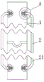
In order to achieve the above object, the present invention provides the following technical solutions: the utility model provides a two-period form oil drill pipe, includes the drilling rod body, drilling rod body lateral wall is equipped with protection machanism, drilling rod body inside wall is equipped with clean mechanism, protection machanism includes the lag, sealed pad, recess and gyro wheel, drilling rod body lateral wall one side is seted up flutedly, the inside gyro wheel that is equipped with of recess, gyro wheel lateral wall one side is connected with the lag, the recess inside wall corresponds lag position department is connected with sealed the pad.
Preferably, the width of the groove is larger than that of the roller.
Preferably, the shape of the protective sleeve is cylindrical, and the length of the protective sleeve is smaller than that of the drill rod body.
Preferably, the cleaning mechanism comprises a fixing clamp, and the fixing clamp is connected to one side of the outer side wall of the drill rod body.
Preferably, the cleaning mechanism further comprises a connecting plate, and the lower end of the fixing clamp is connected with the connecting plate.
Preferably, the cleaning mechanism further comprises an electric push rod and a telescopic hose, wherein the electric push rod is connected to one side of the outer side wall of the connecting plate, and the telescopic hose is connected to one side of the outer side wall of the connecting plate, which is close to the outer side of the electric push rod.
Preferably, the cleaning mechanism further comprises a motor box and a motor, the electric push rod is far away from one end of the connecting plate and is connected with the motor box, and the motor is connected inside the motor box.
Preferably, the cleaning mechanism further comprises a support, and the support is connected to the middle position of the outer side wall of the motor box.
Preferably, the cleaning mechanism further comprises bristles and a cleaning cover, one end of the motor is connected with the cleaning cover, and the outer side wall of the cleaning cover is connected with the bristles.
In the technical scheme, the utility model provides a technological effect and advantage:
1. through the setting of lag, sealed pad and gyro wheel, make the drilling rod at the in-process that carries out oil exploration drilling, the lag protects the drilling rod, prevents the friction that drilling earth stone caused drilling rod pivoted in-process, and the protective sheath can not rotate along with the rotation of drilling rod under the effect of gyro wheel, prevents to cause great wearing and tearing to the lag, makes the life extension of lag and drilling rod.
2. Through the setting of clean cover, electric putter and motor, make the staff when clearing up the spot that the drilling rod is infected with at the in-process that carries out oil exploration drilling, the accessible is connected the one end at the drilling rod with the fixation clamp with the motor case, drives clean cover through the motor and rotates to the inner wall to the drilling rod is cleared up under the effect that electric putter stretches out and draws back to carry out the position removal, alleviates staff's intensity of labour, can not cause the inside jam of drilling rod, influences the condition of drilling rod normal use.
Drawings
In order to more clearly illustrate the embodiments of the present application or the technical solutions in the prior art, the drawings needed to be used in the embodiments will be briefly described below, and it is obvious that the drawings in the following description are only some embodiments described in the present invention, and other drawings can be obtained by those skilled in the art according to these drawings.
Fig. 1 is a schematic view of the present invention.
Fig. 2 is a schematic view of the protection mechanism of the present invention.
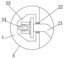
Fig. 3 is an enlarged schematic view of a portion a of fig. 2 according to the present invention.
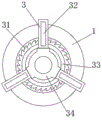
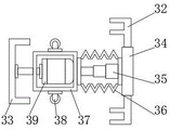
Fig. 4 is a schematic view of the cleaning mechanism of the present invention.
Fig. 5 is a schematic view of the fixing clip of the present invention.
Description of reference numerals:
1. a drill rod body; 2. a protection mechanism; 21. a protective sleeve; 22. a gasket; 23. a groove; 24. a roller; 3. a cleaning mechanism; 31. brushing; 32. a fixing clip; 33. a cleaning hood; 34. a connecting plate; 35. An electric push rod; 36. a flexible hose; 37. a motor case; 38. a support; 39. an electric motor.
Detailed Description
Example embodiments will now be described more fully with reference to the accompanying drawings. Example embodiments may, however, be embodied in many different forms and should not be construed as limited to the examples set forth herein; rather, these example embodiments are provided so that this disclosure will be thorough and complete, and will fully convey the concept of example embodiments to those skilled in the art. The drawings are merely schematic illustrations of the present disclosure and are not necessarily drawn to scale. The same reference numerals in the drawings denote the same or similar parts, and thus their repetitive description will be omitted.
Furthermore, the described features, structures, or characteristics may be combined in any suitable manner in one or more example embodiments. In the following description, numerous specific details are provided to give a thorough understanding of example embodiments of the disclosure. One skilled in the relevant art will recognize, however, that the subject matter of the present disclosure can be practiced without one or more of the specific details, or with other methods, components, steps, and so forth. In other instances, well-known structures, methods, implementations, or operations are not shown or described in detail to avoid obscuring aspects of the disclosure.
The utility model provides a two-period form oil drill pipe as shown in fig. 1-5, including drilling rod body 1, drilling rod body 1 lateral wall is equipped with protection machanism 2, and drilling rod body 1 inside wall is equipped with clean mechanism 3, and protection machanism 2 includes lag 21, sealed pad 22, recess 23 and gyro wheel 24, and recess 23 has been seted up to drilling rod body 1 lateral wall one side, and recess 23 inside is equipped with gyro wheel 24, and gyro wheel 24 lateral wall one side is connected with lag 21, and the corresponding lag 21 position department of recess 23 inside wall is connected with sealed pad 22.
Further, in the above technical solution, the width of the groove 23 is larger than the width of the roller 24; preventing the rollers 24 from being obstructed by the grooves 23 during the performance of the activity.
Further, in the above technical scheme, the shape of the protective sleeve 21 is cylindrical, and the length of the protective sleeve 21 is smaller than that of the drill rod body 1; the protective sleeve 21 is convenient to be mounted on the drill rod body 1.
Further, in the above technical solution, the cleaning mechanism 3 includes a fixing clamp 32, and one side of the outer side wall of the drill rod body 1 is connected with the fixing clamp 32; facilitating the fixing of the position of the equipment on the connection plate 34.
Further, in the above technical solution, the cleaning mechanism 3 further includes a connecting plate 34, and the lower end of the fixing clip 32 is connected with the connecting plate 34; to provide support for the motor casing 37.
Further, in the above technical solution, the cleaning mechanism 3 further includes an electric push rod 35 and a flexible hose 36, the electric push rod 35 is connected to one side of the outer side wall of the connecting plate 34, and the flexible hose 36 is connected to one side of the outer side wall of the connecting plate 34, which is close to the outer side of the electric push rod 35; be convenient for protect electric putter 35, prevent that electric putter 35 from receiving the influence of external sewage.
Further, in the above technical solution, the cleaning mechanism 3 further includes a motor box 37 and a motor 39, one end of the electric push rod 35, which is far away from the connecting plate 34, is connected with the motor box 37, and the motor 39 is connected inside the motor box 37; it is convenient to provide support for the motor 39 and prevent the motor 39 from being damaged by external sewage.
Further, in the above technical solution, the cleaning mechanism 3 further includes a bracket 38, and the bracket 38 is connected to the middle position of the outer side wall of the motor box 37; so as to support the motor box 37 to slide in the drill rod body 1.
Further, in the above technical solution, the cleaning mechanism 3 further includes bristles 31 and a cleaning cover 33, one end of the motor 39 is connected with the cleaning cover 33, and the outer side wall of the cleaning cover 33 is connected with the bristles 31; the cleaning cover 33 can rotate under the action of the motor 39 to clean the inner wall of the drill rod body 1.
In the utility model, the electric push rod 35 is sold by Youth electromechanical device of Yangzhou, and the model is DTZ type electric push rod; the motor 39 is a model number Y2-160L-4 pole motor sold by lambobo motors limited, taizhou.
This practical theory of operation: through the arrangement of the protective sleeve 21, the sealing gasket 22 and the roller 24, the protective sleeve 21 protects the drill rod in the process of drilling the drill rod for petroleum exploration, the friction of soil blocks in the drilling hole on the drill rod in the rotating process is prevented, the protective sleeve 21 cannot rotate along with the rotation of the drill rod under the action of the roller 24, the protective sleeve 21 is prevented from being greatly abraded, the service lives of the protective sleeve 21 and the drill rod are prolonged, through the arrangement of the cleaning cover 33, the electric push rod 35 and the motor 39, when workers clean up stains stained in the process of drilling the drill rod in the petroleum exploration, the motor box 37 can be connected to one end of the drill rod through the fixing clamp 32, the cleaning cover 33 is driven to rotate through the motor 39, the inner wall of the drill rod is cleaned under the action of position movement of the electric push rod 35 in a stretching mode, and the labor intensity of the workers is relieved, the blockage in the drill rod can not be caused, and the normal use condition of the drill rod is not influenced.
While certain exemplary embodiments of the present invention have been described above by way of illustration only, it will be apparent to those of ordinary skill in the art that the described embodiments may be modified in various different ways without departing from the spirit and scope of the present invention. Accordingly, the drawings and description are illustrative in nature and should not be construed as limiting the scope of the invention.
Claims (9)
1. The utility model provides a two-stage type oil drill pipe, includes drilling rod body (1), its characterized in that: drilling rod body (1) lateral wall is equipped with protection machanism (2), drilling rod body (1) inside wall is equipped with clean mechanism (3), protection machanism (2) are including lag (21), sealed pad (22), recess (23) and gyro wheel (24), drilling rod body (1) lateral wall one side is seted up recess (23), recess (23) inside is equipped with gyro wheel (24), gyro wheel (24) lateral wall one side is connected with lag (21), recess (23) inside wall corresponds lag (21) position department is connected with sealed pad (22).
2. A two-stage oil drill pipe according to claim 1, characterized in that the width of the groove (23) is greater than the width of the roller (24).
3. A two-section oil drill pipe according to claim 1, characterized in that the protective sleeve (21) is cylindrical in shape and the length of the protective sleeve (21) is less than the length of the drill pipe body (1).
4. A two-stage petroleum drill pipe according to claim 1, characterized in that the cleaning mechanism (3) comprises a fixing clamp (32), and the fixing clamp (32) is connected to one side of the outer side wall of the drill pipe body (1).
5. A two-stage oil drill pipe according to claim 4, characterized in that the cleaning mechanism (3) further comprises a connecting plate (34), and the lower end of the fixing clamp (32) is connected with the connecting plate (34).
6. The two-section oil drill pipe as claimed in claim 5, characterized in that the cleaning mechanism (3) further comprises an electric push rod (35) and a flexible hose (36), the electric push rod (35) is connected to one side of the outer side wall of the connecting plate (34), and the flexible hose (36) is connected to one side of the outer side wall of the connecting plate (34) close to the outer side of the electric push rod (35).
7. The two-section oil drill pipe as claimed in claim 6, characterized in that the cleaning mechanism (3) further comprises a motor box (37) and a motor (39), the end of the electric push rod (35) far away from the connecting plate (34) is connected with the motor box (37), and the motor (39) is connected inside the motor box (37).
8. A two-section oil drill pipe according to claim 7, characterized in that the cleaning mechanism (3) further comprises a bracket (38), and the bracket (38) is connected to the middle position of the outer side wall of the motor box (37).
9. The two-section oil drill pipe as claimed in claim 7, characterized in that the cleaning mechanism (3) further comprises bristles (31) and a cleaning cover (33), the cleaning cover (33) is connected to one end of the motor (39), and the bristles (31) are connected to the outer side wall of the cleaning cover (33).
Priority Applications (1)
| Application Number | Priority Date | Filing Date | Title |
|---|---|---|---|
| CN202020816542.7U CN212563113U (en) | 2020-05-17 | 2020-05-17 | Two-section type oil drill pipe |
Applications Claiming Priority (1)
| Application Number | Priority Date | Filing Date | Title |
|---|---|---|---|
| CN202020816542.7U CN212563113U (en) | 2020-05-17 | 2020-05-17 | Two-section type oil drill pipe |
Publications (1)
| Publication Number | Publication Date |
|---|---|
| CN212563113U true CN212563113U (en) | 2021-02-19 |
Family
ID=74624459
Family Applications (1)
| Application Number | Title | Priority Date | Filing Date |
|---|---|---|---|
| CN202020816542.7U Active CN212563113U (en) | 2020-05-17 | 2020-05-17 | Two-section type oil drill pipe |
Country Status (1)
| Country | Link |
|---|---|
| CN (1) | CN212563113U (en) |
Cited By (2)
| Publication number | Priority date | Publication date | Assignee | Title |
|---|---|---|---|---|
| CN113026972A (en) * | 2021-04-07 | 2021-06-25 | 海南科技职业大学 | One-time embedded water stop joint for drainage of constructional engineering and construction method thereof |
| CN113353196A (en) * | 2021-05-11 | 2021-09-07 | 海南科技职业大学 | Weather monitoring device for marine safety |
-
2020
- 2020-05-17 CN CN202020816542.7U patent/CN212563113U/en active Active
Cited By (3)
| Publication number | Priority date | Publication date | Assignee | Title |
|---|---|---|---|---|
| CN113026972A (en) * | 2021-04-07 | 2021-06-25 | 海南科技职业大学 | One-time embedded water stop joint for drainage of constructional engineering and construction method thereof |
| CN113353196A (en) * | 2021-05-11 | 2021-09-07 | 海南科技职业大学 | Weather monitoring device for marine safety |
| CN113353196B (en) * | 2021-05-11 | 2022-06-28 | 海南科技职业大学 | Weather monitoring device for marine safety |
Similar Documents
| Publication | Publication Date | Title |
|---|---|---|
| CN212563113U (en) | Two-section type oil drill pipe | |
| KR101711634B1 (en) | Apparatus for Cleaning the inner of Deep Well capable of Expand a Brush | |
| CN210386834U (en) | Tunnel pipeline surface cleaning device | |
| CN2931775Y (en) | Highly effective pipeline scraper | |
| CN104594853A (en) | Rotary type casing pipe scrapper and scrapping method | |
| CN208220648U (en) | A kind of rotary digging driver drilling rod cleaning mechanism | |
| CN210386844U (en) | Large tracts of land cable duct lays pull throughs | |
| CN216791696U (en) | Sampling device for engineering geological investigation | |
| CN212337201U (en) | Drilling dust removal device | |
| CN211474054U (en) | Protective device for crawler drill | |
| CN207315275U (en) | One kind mill, set milling workover tool | |
| CN201771432U (en) | Bore hole cleaner | |
| CN112523683A (en) | Drilling device and exploration method for metal ore exploration | |
| CN207063907U (en) | Rig with slopes operation locking device | |
| CN208966204U (en) | A kind of rock drill protection probe | |
| CN212263355U (en) | Geological logging rock debris grinding bowl body | |
| JP3965591B2 (en) | Percussion wire line sampling device | |
| CN211387016U (en) | Portable electric power rig of pit base | |
| CN213234992U (en) | Drilling rig for geotechnical engineering investigation | |
| CN210059088U (en) | Drilling rod screw thread belt cleaning device | |
| CN212272059U (en) | Centralizer for sand flushing drill mill of horizontal well | |
| CN215108829U (en) | Underground fishing and well washing device for geothermal well | |
| CN219197291U (en) | Device for cleaning mud skin on inner wall of rope drill rod | |
| CN216646502U (en) | Hand-held type ground exploration device | |
| CN218956142U (en) | Sampling device for mine geology detection |
Legal Events
| Date | Code | Title | Description |
|---|---|---|---|
| GR01 | Patent grant | ||
| GR01 | Patent grant |