JP3965589B2 - Pachinko machine - Google Patents
Pachinko machine Download PDFInfo
- Publication number
- JP3965589B2 JP3965589B2 JP35307095A JP35307095A JP3965589B2 JP 3965589 B2 JP3965589 B2 JP 3965589B2 JP 35307095 A JP35307095 A JP 35307095A JP 35307095 A JP35307095 A JP 35307095A JP 3965589 B2 JP3965589 B2 JP 3965589B2
- Authority
- JP
- Japan
- Prior art keywords
- positioning
- hole
- game board
- back surface
- positioning hole
- Prior art date
- Legal status (The legal status is an assumption and is not a legal conclusion. Google has not performed a legal analysis and makes no representation as to the accuracy of the status listed.)
- Expired - Lifetime
Links
- 238000004519 manufacturing process Methods 0.000 description 14
- 239000004973 liquid crystal related substance Substances 0.000 description 9
- 230000036961 partial effect Effects 0.000 description 9
- 239000000463 material Substances 0.000 description 8
- 230000007246 mechanism Effects 0.000 description 8
- 230000002950 deficient Effects 0.000 description 7
- 210000005069 ears Anatomy 0.000 description 7
- 238000005553 drilling Methods 0.000 description 4
- 230000008859 change Effects 0.000 description 3
- 230000007547 defect Effects 0.000 description 3
- 230000004048 modification Effects 0.000 description 3
- 238000012986 modification Methods 0.000 description 3
- 244000144985 peep Species 0.000 description 3
- 239000002994 raw material Substances 0.000 description 3
- 239000000470 constituent Substances 0.000 description 2
- 238000005520 cutting process Methods 0.000 description 2
- 230000007123 defense Effects 0.000 description 2
- 238000000034 method Methods 0.000 description 2
- 238000000465 moulding Methods 0.000 description 2
- 230000002093 peripheral effect Effects 0.000 description 2
- 238000005498 polishing Methods 0.000 description 2
- 230000001681 protective effect Effects 0.000 description 2
- 229920005989 resin Polymers 0.000 description 2
- 239000011347 resin Substances 0.000 description 2
- 229930182556 Polyacetal Natural products 0.000 description 1
- 229920000122 acrylonitrile butadiene styrene Polymers 0.000 description 1
- 230000002411 adverse Effects 0.000 description 1
- 230000008901 benefit Effects 0.000 description 1
- 238000013329 compounding Methods 0.000 description 1
- 238000001514 detection method Methods 0.000 description 1
- 230000000694 effects Effects 0.000 description 1
- 230000000414 obstructive effect Effects 0.000 description 1
- 230000000149 penetrating effect Effects 0.000 description 1
- 239000011120 plywood Substances 0.000 description 1
- 229920000515 polycarbonate Polymers 0.000 description 1
- 239000004417 polycarbonate Substances 0.000 description 1
- 229920006324 polyoxymethylene Polymers 0.000 description 1
- 230000002441 reversible effect Effects 0.000 description 1
- 229920003002 synthetic resin Polymers 0.000 description 1
- 239000000057 synthetic resin Substances 0.000 description 1
Images



Landscapes
- Pinball Game Machines (AREA)
- Moulds For Moulding Plastics Or The Like (AREA)
Description
【0001】
【発明の属する技術分野】
本発明は、入賞球誘導用裏樋(以下、「裏樋」という。)を備えたパチンコ遊技機に関する。
【0002】
【従来の技術】
パチンコ遊技機の遊技盤(以下、「遊技盤」という。)71の裏面には、図8に示す様な裏樋72が取着されることが多い。この裏樋72は、遊技盤71の裏面に導かれた入賞球の誘導経路を形成するためのものである。そして、この裏樋72を、遊技盤71の裏面に正確に取着することを意図して、この裏面に位置決め穴711を穿設し、裏樋72の前方部の適所に、この位置決め穴711に対応する位置決め突起721が設けられることが多い(特開平2−74276号公報等)。
【0003】
【発明が解決しようとする課題】
しかしながら、上記従来の裏樋72には、以下の様な問題点がある。即ち、位置決め穴711は、ドリル等を用いて穿設されることが多いが、この位置決め穴711の中には、図8に示す様に、底面部に「削り残し」、「削り損じ」、「バリ」等の不良箇所Fが存在するものがある。そして、この様な位置決め穴711には、位置決め突起721を十分に嵌め込むことは困難なため、裏樋72が、遊技盤71の裏面より浮いた状態となることが多い。この結果、裏樋72に搭載される可動部品の動作に悪影響を与えることが多い。例えば、「アタッカー開成用機構」の裏樋72から離間すべき部材が、この浮いた状態の裏樋72に接触し、この機構の可動を困難にすることがある。具体的には、図8に示す様に、開成用ソレノイドの軸81及びアタッカーの扉(図示しない。)の間に掛け渡された連結部材82等が、この浮いた状態の裏樋72に接触することがある。
また、裏樋72の上に、防護用のカバーを取着する場合にも、この取着が困難になり易い。
【0004】
一方、(1)位置決め穴711の穿設に用いられるドリル等の治具を頻繁に研磨し、「不良箇所」Fの発生を未然に防止したり、(2)穿設される位置決め穴711毎に、「不良箇所」Fの発生の有無の確認し、発生した「不良箇所」Fを削り取る作業等を行うことも考えられるが、これらの作業を行えば、裏樋72、引いては、パチンコ遊技機(以下、「パチンコ機」という。)の製造コストを高くすることになる。
以上の様な事情より、穿設される位置決め穴711の仕上がり状態が、少々、悪くても、これに対処できる裏樋等の出現が従来より切望されていた。
【0005】
本発明は、上記観点に鑑みてなされてものであり、遊技盤の裏面に設けられた位置決め穴の仕上がり状態が少々悪くても、この裏面に正確に取着できる裏樋を備えたパチンコ遊技機を提供することを目的とする。
【0006】
【課題を解決するための手段】
前記目的を達成するため請求項1に係るパチンコ遊技機は、裏面にドリルにより削られて穿設され、有底である位置決め穴を有する遊技盤と、前記位置決め穴に対し、樋底面に対向する開放部の存在する前方部の適所より突出されると共に、前記遊技盤の裏面に取着される際に、該位置決め穴に嵌め込まれる位置決め突起を有し、前記遊技盤の裏面に取着されて、該遊技盤の裏面に導かれた入賞球を誘導するための誘導経路を形成する入賞球誘導用裏樋と、を備えたパチンコ遊技機において、前記位置決め突起は、前記開放部の端縁から延出された複数の耳部のうち、ビス孔が設けられていない耳部に設けられると共に前記入賞球誘導用裏樋の表裏を貫通する貫通孔を有し、前記位置決め突起の外径形状は円形状であり、前記貫通孔の横断面形状は円形に形成されていることを特徴とする。
【0007】
前記請求項1に係るパチンコ遊技機においては、遊技盤の裏面にドリルにより削られて穿設され、有底である位置決め穴に嵌め込まれる入賞球誘導用裏樋の位置決め突起に、入賞球誘導用裏樋の表裏を貫通する貫通孔が形成されているので、対応する位置決め穴に、上記の様な「不良箇所」が存在しても、この「箇所」を貫通孔の内部に収め、邪魔にならない様にしながら、裏樋の取着を行える。また、本裏樋を用いれば、位置決め穴の仕上がり状態が少々、悪くてもよいため、位置決め穴の穿設治具(「ドリル」等)の研磨間隔を長くしたり、一の治具の使用期間を長くできる。また、穿設される位置決め穴の不良の有無の確認や、修正等の作業を不要にできるたため、裏樋、引いては、パチンコ機の製造効率の向上及び製造コストの低廉化に寄与できる。
ここに、請求項2に記載されているように、前記位置決め穴は、底面部と側壁部を有する刳り抜かれた状態のものであり、前記位置決め突起の突出端は、前記位置決め突起の突出端を前記位置決め穴に嵌め込んだ状態で、前記位置決め穴の底面部及び側壁部に囲まれるように構成されることが望ましい。
【0008】
本裏樋は、(イ)2以上の部分により構成されたものであっても、(ロ)一体品であってもよい。尚、前者(イ)の場合、パチンコ機のモデルチェンジ等に伴い、一の部分の形状変更が必要な場合にも、残りの部分を、そのまま使用できるというメリットがある。
上記「位置決め突起」の平面形状は、円形リング形状、楕円形リング形状とされることが多いが、三角リング形状、多角形リング形状等の他の形状であってもよい。また、上記「位置決め突起」の高さは、対応する「位置決め穴」の深さとの関係を考慮して定められる。尚、「位置決め穴」の深さは、「遊技盤の前面から打ち込まれた釘」の先端部に抵触しない範囲(「位置決め穴の底面部」より、この「先端部」が突出しない範囲)で定められる。
【0009】
また、上記「位置決め突起」が中空部を備える場合には、該位置決め突起を突出させる箇所に、中空部の側に開口する凹み穴を設けて、該中空部が凹み穴と連続していてもよい。
更に、本裏樋の構成素材、製造方法等は特に問わないが、所定の樹脂系原料を用いて製造すれば、製造効率の向上、製造コストの低廉を図ることが容易になる。尚、「樹脂系原料」の種類、配合組成等は種々選択されるが、例えば、ポリカーボネート、ABS、ポリアセタール等を主体とする素材等を例示できる。
【0010】
【発明の実施の形態】
以下、本発明の実施の形態を説明する。
本裏樋2は、図1に示す様な遊技盤1の裏面に取着されるものである。
この遊技盤1は、略矩形板状のベニア合板(板厚;19.5mm)を用いて構成されおり、上方寄りの略中央には、図2に示す様な覗き孔hが設けられている。また、図1に示す様に、遊技盤1の裏面には、この覗き孔hに蓋をする様な状態で、液晶表示装置Eが取着されている。更に、遊技盤1の前方からは、この覗き孔hを通じ、液晶表示装置Eの表示面が目視可能とされている。
【0011】
また、遊技盤1の裏面の液晶表示装置Eの下方には、アタッカー(図示しない。)の可動を行うアタッカー開成機構Gが取着されている。更に、遊技盤1の液晶表示装置Eの配置箇所の両脇には、入賞口11、12が設けられている。また、これらの下方にも、入賞口13、14が設けられている。更に、アタッカー開成機構Gの配置箇所の上方には、液晶表示装置Eを動作させるための始動入賞口15が設けられている。また、この箇所の両脇にも、入賞口16、17が設けられている。但し、各入賞口11〜17の配置箇所、配置数等は、本形態に示すものに限らない。
また、入賞口11、12の上方には、図1及び図3(a)に示す様な位置決め穴(穴径;8〜16mmφ、深さ;3〜3.5mm)181、182が設けられている。更に、入賞口16、17の内側にも、図1及び図3(b)に示す様な位置決め穴(穴径;8〜16mmφ、深さ;3〜3.5mm)183、184が設けられている。但し、各位置決め穴181〜184の配置箇所、配置数等は、図1に示すものに限らない。尚、図1では、遊技盤1の裏面に配置される各部材のうちで、裏樋2、液晶表示装置E及びアタッカー開成機構Gのみを図示し、これら以外の部材(各配線、入賞球検出装置等)の図示を省略している。
【0012】
一方、上記裏樋2は、半透明な合成樹脂材を用いて構成され、遊技盤1の裏面21の上方側に取着される上方部2aと、下方側に取着される下方部2bとからなる。但し、この上方部2a及び下方部2bが一体とされた裏樋2であってもよい。
このうち、上方部2aは、本体部(板厚;2mm)21aと、その上方側、中間側及び下方側の各両脇に配置された耳部(板厚;2mm)M1〜M6とを備えている。
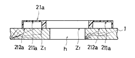
この本体部21aは、略アーチ状の樋経路を描いる。そして、図2に示す様に、樋底面211aを遊技盤1の裏面と離間させつつ、この樋底面211aに対向する開放部212a(樋経路に沿った開方端縁)を、遊技盤1の裏面に略接触若しくは近接させている。
【0013】
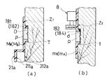
また、耳部M1〜M6は、いずれも、略板状の外形とされ、本体部21aの側壁の開放部212a側の端縁から略水平に配置されている。〔3(a)参照)〕。更に、耳部M1〜M6のうちで、中間側に配置されるものM5及びM6の略中心には、図3(a)に示す様に、表裏両面を貫通する貫通孔(孔径;17〜17.2mmφ)Dが設けられている。また、この孔Dの周囲からは、この孔Dと連通する中空部(孔径;12mmφ)Pを備えた位置決め突起(高さ;2.5mm、根元側の外形;17mmφ、突出端側の外形;15mmφ)Tが突出されている。尚、図3(a)に示す様に、位置決め突起Tの外径が、突出端側に行くに従って絞り込まれているのは、(1)各突起Tの位置決め穴181、182への嵌入を容易にすると共に、(2)裏樋2の成形時に、この突起Tの周囲に、「ひけ」等の成形不良が発生することを防止するためである。そして、各位置決め突起T、Tの間隔は、遊技盤1の裏面の上方側で、左右に並ぶ位置決め穴181、182の間隔に略対応している。
【0014】
また、残りの耳部M1〜M4の略中央には、ビス孔が設けられられている。
そして、図1及び3(a)に示す様に、各置決め用突起T、Tを、対応する各位置決め穴181、182に嵌め込めば、上方部2aは、遊技盤1の裏面の上方側に位置合わせされる。更に、耳部M1〜M4のビス孔に向かって、所定の固定用ビスQを打ち込めば、上方部1aは、図1に示す様に遊技盤1の裏面に固定される。このとき、上方部2aの前方部Z1〔図2及び3(a)参照〕のうちで、各耳部M1 〜M6 等が、遊技盤1の裏面に接触した状態となる。
その際、図3(a)に示す様に、各位置決め穴181、182の底面に、不良箇所Fが存在しても、この箇所Fは中空部Pの内部に納まる。従って、各位置決め穴181、182の仕上がり状態が、少々悪くても、遊技盤1の裏面に正確に取着できる。
そして、この上方部2aは、遊技盤1の裏面側に、液晶表示装置Eの下方を除く箇所を取り囲む誘導経路を形成する。この誘導経路は、液晶表示装置Eの両脇の入賞口11、12を通じ、遊技盤1の裏面に導かれた入賞球を誘導する。また、この様に誘導される入賞球は、上方部2aの下端の開口部253a、254aを通じて、下方部2bの方向へと導かれる。
【0015】
一方、下方部2bも、略アーチ状の外形とされた本体部21bと、本体部21bの上下両脇から略水平に突出する耳部m1 〜m4 と、本体部21bの一対の傾斜壁から下方側に突出する耳部m5、m6とを備えている。そして、下方側に突出する耳部m5、m6には、図3(b)に示す様に、上記貫通孔Dと同様な貫通孔dが設けられている。また、これらの耳部m5、m6のこの貫通孔dの周囲からは、上記中空部Pと同様な中空部pを備えた同様な位置決め突起tが突出している。更に、下方部2bの左右に並ぶ位置決め突起t、tの間隔は、遊技盤1の裏面の下方側で、左右に並ぶ位置決め穴183、184の間隔に略対応している。更に、残りの耳部m1〜m4にも、固定用ビスqが打ち込まれるビス孔(図示しない。)が設けられている。
【0016】
そして、この下方部2bも、対応する位置決め穴183、184の仕上がり状態によらず、遊技盤1の裏面に正確に取着できる。このとき、下方部2bの前方部Z2〔図3(b)参照〕のうちで、各耳部m1〜m6等が、遊技盤1の裏面に接触した状態となる。
また、この下方部2bは、アタッカー開成機構Gの下方側を除く箇所を取り囲む誘導経路を形成する。この誘導経路は、上方部2aの下端の開口部253a、254aを通じて流下する入賞球を、上端の開口部251b、252bで補給し、下端の開口部253b、254bへと誘導する。これと同時に、これらの誘導経路の守備範囲に設けられた入賞口13〜17を通じて、遊技盤1の裏面に導かれた入賞球の誘導を行う。
但し、上記誘導経路の各守備範囲に、更に別の入賞口が設けられれば、各誘導経路は、これらの入賞口で導かれた入賞球の誘導をも行うことになる。
【0017】
以上の様に構成される上方部2a及び下方部2bは、図4に示す様な金型を用いて容易に、一体成形できる。
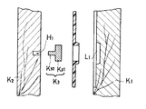
この金型は、上型K1と、下型K2と、孔形成用部材K3を備えている。
このうち、上型K1は、所定の金型素材の下面側(衝合面側)に切削加工を施して作製されたものである。また、下型K2は、所定の金型素材を、そのまま用いたものである。但し、上型K1の下面側及び上型K1の上面側(衝合面側)の双方に切削加工を施して作製された金型であってもよい。
更に、下型K2 の上面側のうちで、各位置決め突起T、tの形成される箇所には、取付穴H1 が穿設されている。
【0018】
また、上記孔形成用部材K3 は、略円柱状の凸状部K31と、凸状部K31の裏面から突出するピン状部K32とを備えている。そして、この凸状部K31は、各貫通孔及び各中空部が連通して構成される連通状の孔(D及びP、d及びpが形成する孔)の孔形状と、凹凸の反転した凸形状とされている。また、この凸状部K31は、ピン状部K32を取付穴H1に嵌入することにより、下型K2の上面側に固定される。尚、ピン状部K32の側周面に雄螺子部を設け、取付穴H1の内周面にこれと螺合する雌螺子部を設けることもできる。
そして、孔形成用部材K3 を、下型K2 の上面側に取着した後に、上型K1及び下型K2の衝合面を合わせ、型閉状態にすれば、上型K1及び下型K2の間に、上方部1a若しくは下方部1bの外形と凹凸の反転した形状の成形空間が形成される。
【0019】
以上の様に、本裏樋2は、位置決め穴181〜184の仕上がり状態が少々、悪くても、遊技盤1の裏面に正確に取着できる。そして、本裏樋2は、図3(b)に示す様に、裏樋2に「アタッカー開成機構」G等を搭載したり、防護用のカバーを取着する場合に、特に好適である。
また、この裏樋2を用いれば、位置決め穴181〜184の仕上がり状態をあまり気にする必要がないため、裏樋2、引いては、パチンコ機の製造効率の向上及び製造コストの低廉化に寄与できる。更に、本裏樋2は、金型を用いて容易に一体成形できるため、製造コストを低く抑えられる。
【0020】
また、上記金型は、パチンコ機のモデルチェンジ等に伴い、裏樋2における各置決め用突起T、tの形成箇所等の変更があっても、以下に示す「手直し」を行えば、瞬時に対応できる。即ち、図4の上型K1の切削加工された部分のうちで、各置決め用突起T、tの形成するための縦断面台形状の凹状部L1 を、上型K1の構成素材と同様な素材で充填する。次いで、新たな突起T、tに対応する上型K1の部分を切削し、新たな凹状部を形成する。そして、下型K2の取付穴H1 を充填した後に、新たな突起T、tを形成する箇所に、新たな取付穴を設ければ足りる。これに対し、凸状部K31が、下型K2 の上面側と一体不可分になっていれば、下型K2の手直しには、大きな手間が必要となる。即ち、下型K2の上面側の凸状部K31を除く箇所を、上記素材で充填した後に、新たな凸状部以外の箇所を切削する必要があるからである。この様に、本金型では、上記「手直し」を容易に行える。
【0021】
また、中空部P、pの大きさを変更する場合は、孔形成用部材K3を所望の外径を備えるものに交換すれば足りる。
更に、図5に示す様に、孔形成用部材K3を上型K1の側に取着すれば、「手直し」が一層、容易になる。即ち、上型K1の凹状部L2及び取付穴H2を、上記素材で充填した後、新たな凹状部及び取付穴を形成すれば足りる。即ち、上型K1の修正のみで、対処できるからである。
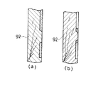
また、本形態では、耳部M5、M6、m5、m6に貫通孔D、dを設けたが、図6(a)、(b)に示す様に、貫通孔D、dを備えない裏樋2m、2nとしてもよい。また、これらの場合、図6(b)に示す様に、突出端側に凹み部Rを備えた位置決め突起T、tとすることもできる。更に、耳部M5、M6、m5、m6に、貫通孔D、dの代わりに、中空部P、pと連続状態となる凹み穴を設けてもよい。
更に、これらの裏樋2m、2n等を製造するための金型は、図5の金型に簡単な改良を加えること等により得られる。例えば、図7に示す様に、図5の孔形成用部材K3を、凸状部K31を薄手にして構成される穴形成用部材K5に取り替えれば足りる。
【0022】
尚、本発明においては、上記具体的な実施の形態に示すものに限らず、目的、用途に応じて本発明の範囲内で種々変更した別の実施の形態、変形的な形態、別の実施例、変形例とすることができる。即ち、上方部2a、下方部2bにおける各位置決め突起T、tの配置箇所、配置数、サイズ等は、本形態に示すものに限らない。
【0023】
【発明の効果】
以上の様に、本発明に係るパチンコ遊技機では、遊技盤の裏面にドリルにより削られて穿設され、有底である位置決め穴に嵌め込まれる入賞球誘導用裏樋の位置決め突起に、入賞球誘導用裏樋の表裏を貫通する貫通孔が形成されているので、対応する位置決め穴に、「削り残し」、「バリ」等の「不良箇所」が存在しても、この「箇所」を貫通孔の内部に収め、邪魔にならない様にしながら、裏樋の取着を行える。また、本裏樋を用いれば、位置決め穴の仕上がり状態が少々、悪くてもよいため、位置決め穴の穿設治具(「ドリル」等)の研磨間隔を長くしたり、一の治具の使用期間を長くできる。また、穿設される位置決め穴の不良の有無の確認や、修正等の作業を不要にできるたため、裏樋、引いては、パチンコ機の製造効率の向上及び製造コストの低廉化に寄与できる。
【図面の簡単な説明】
【図1】 発明の実施の形態に係わる裏樋が遊技盤の裏面に取着された状態を示す概略的な説明図である。
【図2】 図1の裏樋及び遊技盤の覗き孔を通る水平面で切断した概略的な縦断面図である。
【図3】 (a)図1の上方部2a及び遊技盤1を位置決め突起Tの中心を通る垂直面で切断した概略的な縦断面図、(b)図1の下方部2b及び遊技盤1を位置決め突起tの中心を通る垂直面で切断した概略的な縦断面図である。
【図4】 図1の裏樋及びこの裏樋を製造するための金型の概略的な一部縦断面図である。
【図5】 図4の変形例に係わる金型の概略的な一部縦断面図である。
【図6】 (a)発明の実施の形態の変形例に係わる裏樋を遊技盤の裏面に取着した状態を示す概略的な一部縦断面図、(b)発明の実施の形態の変形例に係わる裏樋を遊技盤の裏面に取着した状態を示す概略的な一部縦断面図である。
【図7】 図6(a)、(b)に示す裏樋の製造するための金型の概略的な一部縦断面図である。
【図8】 従来例に係わる裏樋を遊技盤の裏面に取着した状態を示す概略的な一部縦断面図である。
【図9】 従来例に係わる裏樋及びこの裏樋を製造するための金型の概略的な一部縦断面
図である。
【図10】 (a)従来例に係わる金型に手直しを施す手順を示す概略的な一部縦断面図、(b)従
来例に係わる金型に手直しを施す手順を示す概略的な一部縦断面図である。
【符号の説明】
1;遊技盤、11〜17;入賞口、181〜184;位置決め穴、E;液晶表示装置、G;アタッカー開成機構、2;裏樋、2a;上方部、211a;樋底面、212a;開放部、2b;下方部、M1〜M6、m1〜m6;耳部、D、d;貫通孔、P、p;中空部、T、t;位置決め突起、K1;上型、K2;下型、H1、H2;取付穴、K3;孔形成用部材、K31;凸状部、K32;ピン状部。[0001]
BACKGROUND OF THE INVENTION
The present invention relates to a pachinko gaming machine provided with a winning ball guiding back cage (hereinafter referred to as “back cage”).
[0002]
[Prior art]
8 is often attached to the back side of a game board (hereinafter referred to as “game board”) 71 of a pachinko gaming machine. The
[0003]
[Problems to be solved by the invention]
However, there are the following problems in the
In addition, when a protective cover is attached on the
[0004]
On the other hand, (1) a jig such as a drill used for drilling the
Under the circumstances as described above, it has long been desired to develop a back cover or the like that can cope with the pierced
[0005]
The present invention has been made in view of the above viewpoint, and even if the finished state of the positioning hole provided on the back surface of the game board is a little worse, the pachinko gaming machine is provided with a back hook that can be accurately attached to the back surface. The purpose is to provide.
[0006]
[Means for Solving the Problems]
In order to achieve the above object, a pachinko gaming machine according to
[0007]
In the pachinko gaming machine according to the first aspect, the positioning balls for guiding the winning ball are inserted into the positioning protrusions of the winning ball guiding sole that is drilled and drilled on the back surface of the gaming board and is fitted into the bottomed positioning hole. Since the through holes that penetrate the front and back of the back ridge are formed, even if the above-mentioned `` defective location '' exists in the corresponding positioning hole, this `` location '' is stored inside the through hole and is obstructive. You can attach the lining while avoiding it. In addition, if the back of the positioning hole is used, the finished state of the positioning hole may be slightly worse, so the polishing interval of the positioning hole drilling jig (such as “drill”) can be increased or the use of a single jig can be used. The period can be extended. In addition, since it is possible to make it unnecessary to confirm whether there is a defect in the positioning hole to be drilled, and to correct it, it is possible to contribute to improving the manufacturing efficiency of the pachinko machine and reducing the manufacturing cost.
Here, as described in
[0008]
The back cover may be (i) composed of two or more parts, or (b) an integrated product. In the case of the former (b), there is an advantage that the remaining part can be used as it is even when the shape of one part needs to be changed due to the model change of the pachinko machine.
The planar shape of the “positioning protrusion” is often a circular ring shape or an elliptical ring shape, but may be other shapes such as a triangular ring shape or a polygonal ring shape. Further, the height of the “positioning protrusion” is determined in consideration of the relationship with the depth of the corresponding “positioning hole”. The depth of the “positioning hole” is within the range that does not touch the tip of the “nail driven from the front of the game board” (the range where the “tip” does not protrude from the “bottom of the positioning hole”). Determined.
[0009]
Further, when the “positioning protrusion” includes a hollow portion, a recess hole that opens to the hollow portion side is provided at a position where the positioning protrusion protrudes, and the hollow portion is continuous with the recess hole. Good.
Furthermore, there are no particular restrictions on the constituent material, manufacturing method, etc. of the back cover, but if it is manufactured using a predetermined resin raw material, it becomes easy to improve the manufacturing efficiency and reduce the manufacturing cost. In addition, although the kind of a "resin type raw material", a compounding composition, etc. are variously selected, the raw material etc. which have polycarbonate, ABS, polyacetal, etc. as a main body can be illustrated, for example.
[0010]
DETAILED DESCRIPTION OF THE INVENTION
Embodiments of the present invention will be described below.
The
This
[0011]
Also, an attacker opening mechanism G for moving an attacker (not shown) is attached below the liquid crystal display device E on the back surface of the
In addition, positioning holes (hole diameter: 8 to 16 mmφ, depth: 3 to 3.5 mm) 181 and 182 as shown in FIGS. 1 and 3A are provided above the winning
[0012]
On the other hand, the
Among these, the upper part 2a includes a main body part (plate thickness; 2 mm) 21a and ears (plate thickness; 2 mm) M1 to M6 disposed on both sides of the upper side, the middle side and the lower side. ing.
The
[0013]
Further, each of the ear portions M1 to M6 has a substantially plate-like outer shape, and is arranged substantially horizontally from an edge on the
[0014]
A screw hole is provided in the approximate center of the remaining ears M1 to M4.
Then, as shown in FIGS. 1 and 3 (a), if the positioning protrusions T and T are fitted into the corresponding positioning holes 181 and 182, the upper portion 2 a becomes the upper side of the back surface of the
At that time, as shown in FIG. 3A, even if a defective portion F exists on the bottom surface of each
And this upper part 2a forms the guidance path | route surrounding the location except the downward direction of the liquid crystal display device E in the back surface side of the
[0015]
On the other hand, the
[0016]
And this
In addition, the
However, if another winning opening is provided in each defense range of the guiding path, each guiding path also guides the winning ball guided by these winning openings.
[0017]
The upper part 2a and the
This mold includes an upper mold K1, a lower mold K2, and a hole forming member K3.
Among these, the upper die K1 is manufactured by cutting the lower surface side (abutting surface side) of a predetermined mold material. The lower mold K2 uses a predetermined mold material as it is. However, it may be a mold produced by cutting both the lower surface side of the upper die K1 and the upper surface side (abutting surface side) of the upper die K1.
Further, on the upper surface side of the lower mold K2, a mounting hole H1 is formed at a location where the positioning protrusions T and t are formed.
[0018]
The hole forming member K3 includes a substantially cylindrical convex portion K31 and a pin-shaped portion K32 protruding from the back surface of the convex portion K31. And this convex-shaped part K31 has the hole shape of the continuous hole (hole which D and P, d, and p form) comprised by each through-hole and each hollow part, and the convex / convex in which the unevenness | corrugation was reversed. It is made into a shape. Further, the convex portion K31 is fixed to the upper surface side of the lower mold K2 by inserting the pin-shaped portion K32 into the mounting hole H1. A male screw portion can be provided on the side peripheral surface of the pin-shaped portion K32, and a female screw portion that can be screwed with the inner peripheral surface of the mounting hole H1.
Then, after the hole forming member K3 is attached to the upper surface side of the lower mold K2, the abutting surfaces of the upper mold K1 and the lower mold K2 are aligned and the mold is closed, so that the upper mold K1 and the lower mold K2 A molding space having a shape in which the outer shape of the upper portion 1a or the lower portion 1b and the irregularities are inverted is formed therebetween.
[0019]
As described above, the
In addition, if the
[0020]
In addition, even if there is a change in the location of the positioning projections T and t in the
[0021]
When the sizes of the hollow portions P and p are changed, it is sufficient to replace the hole forming member K3 with one having a desired outer diameter.
Further, as shown in FIG. 5, if the hole forming member K3 is attached to the upper mold K1, the “hand-up” is further facilitated. That is, it is sufficient to form a new concave portion and mounting hole after the concave portion L2 and mounting hole H2 of the upper mold K1 are filled with the above-mentioned material. That is, it can be dealt with only by correcting the upper mold K1.
In this embodiment, the through holes D and d are provided in the ears M5, M6, m5, and m6. However, as shown in FIGS. 6 (a) and 6 (b), the back cover without the through holes D and d is provided. It is good also as 2m and 2n. Further, in these cases, as shown in FIG. 6B, the positioning protrusions T and t each having a recessed portion R on the protruding end side may be used. Further, in the ear portions M5, M6, m5, and m6, in place of the through holes D and d, recessed holes that are continuous with the hollow portions P and p may be provided.
Furthermore, the molds for manufacturing these
[0022]
The present invention is not limited to the specific embodiment described above, but may be modified in various ways within the scope of the present invention, modified embodiments, and other implementations depending on the purpose and application. Examples and modifications can be made. That is, the location, number, size, and the like of the positioning protrusions T and t in the upper portion 2a and the
[0023]
【The invention's effect】
As described above, in the pachinko gaming machine according to the present invention, the winning ball is placed on the positioning protrusion of the winning ball guiding back hook which is drilled and drilled on the back surface of the gaming board and is fitted into the bottomed positioning hole. A through-hole that penetrates the front and back of the guide back fence is formed, so even if there is a “defective part” such as “uncut” or “burr” in the corresponding positioning hole, The inside of the hole can be attached, and the lining can be attached while keeping it out of the way. In addition, if the back of the positioning hole is used, the finished state of the positioning hole may be slightly worse, so the polishing interval of the positioning hole drilling jig (such as “drill”) can be increased or the use of a single jig can be used. The period can be extended. In addition, since it is possible to make it unnecessary to confirm whether there is a defect in the positioning hole to be drilled, and to correct it, it is possible to contribute to improving the manufacturing efficiency of the pachinko machine and reducing the manufacturing cost.
[Brief description of the drawings]
FIG. 1 is a schematic explanatory view showing a state in which a back cover according to an embodiment of the invention is attached to the back side of a game board.
FIG. 2 is a schematic longitudinal sectional view cut along a horizontal plane passing through the back wall of FIG. 1 and the viewing hole of the game board.
3A is a schematic longitudinal sectional view of the upper portion 2a and the
FIG. 4 is a schematic partial longitudinal sectional view of the back cover of FIG. 1 and a mold for manufacturing the back cover.
FIG. 5 is a schematic partial longitudinal sectional view of a mold according to a modified example of FIG.
6 (a) is a schematic partial longitudinal sectional view showing a state in which a back cover according to a modification of the embodiment of the invention is attached to the back surface of the game board, and FIG. 6 (b) a modification of the embodiment of the invention. It is a schematic partial longitudinal cross-sectional view which shows the state which attached the back fence concerning the example to the back surface of the game board.
FIG. 7 is a schematic partial longitudinal sectional view of a mold for manufacturing the back cover shown in FIGS. 6 (a) and 6 (b).
FIG. 8 is a schematic partial vertical cross-sectional view showing a state in which a back cage according to a conventional example is attached to the back side of the game board.
FIG. 9 is a schematic partial vertical cross-sectional view of a lining according to a conventional example and a mold for producing the lining.
10A is a schematic partial longitudinal sectional view showing a procedure for reworking a mold according to a conventional example, and FIG. 10B is a schematic partial view showing a procedure for reworking a mold according to a conventional example. It is a longitudinal cross-sectional view.
[Explanation of symbols]
DESCRIPTION OF
Claims (2)
前記位置決め穴に対し、樋底面に対向する開放部の存在する前方部の適所より突出されると共に、前記遊技盤の裏面に取着される際に、該位置決め穴に嵌め込まれる位置決め突起を有し、前記遊技盤の裏面に取着されて、該遊技盤の裏面に導かれた入賞球を誘導するための誘導経路を形成する入賞球誘導用裏樋と、を備えたパチンコ遊技機において、
前記位置決め突起は、前記開放部の端縁から延出された複数の耳部のうち、ビス孔が設けられていない耳部に設けられると共に前記入賞球誘導用裏樋の表裏を貫通する貫通孔を有し、
前記位置決め突起の外径形状は円形状であり、
前記貫通孔の横断面形状は円形に形成されていることを特徴とするパチンコ遊技機。A game board having a positioning hole which is drilled and drilled on the back surface and has a bottom;
The positioning hole protrudes from an appropriate position in the front portion where the open portion facing the bottom surface of the bowl exists, and has a positioning projection that is fitted into the positioning hole when attached to the back surface of the game board. A pachinko gaming machine comprising a winning ball guiding back cage that is attached to the back surface of the gaming board and forms a guiding path for guiding a winning ball guided to the back surface of the gaming board;
The positioning protrusion is provided in an ear portion that is not provided with a screw hole among a plurality of ear portions extending from an edge of the open portion and penetrates through the front and back of the winning ball guiding back cage Have
The outer diameter shape of the positioning protrusion is a circular shape,
A pachinko gaming machine, wherein the through hole has a circular cross-sectional shape.
Priority Applications (1)
| Application Number | Priority Date | Filing Date | Title |
|---|---|---|---|
| JP35307095A JP3965589B2 (en) | 1995-12-29 | 1995-12-29 | Pachinko machine |
Applications Claiming Priority (1)
| Application Number | Priority Date | Filing Date | Title |
|---|---|---|---|
| JP35307095A JP3965589B2 (en) | 1995-12-29 | 1995-12-29 | Pachinko machine |
Related Child Applications (3)
| Application Number | Title | Priority Date | Filing Date |
|---|---|---|---|
| JP37073099A Division JP3229300B2 (en) | 1995-12-29 | 1999-11-19 | Pachinko machine |
| JP37073299A Division JP3229302B2 (en) | 1995-12-29 | 1999-11-19 | Pachinko machine |
| JP37073199A Division JP3229301B2 (en) | 1995-12-29 | 1999-11-19 | Pachinko machine |
Publications (2)
| Publication Number | Publication Date |
|---|---|
| JPH09182855A JPH09182855A (en) | 1997-07-15 |
| JP3965589B2 true JP3965589B2 (en) | 2007-08-29 |
Family
ID=18428360
Family Applications (1)
| Application Number | Title | Priority Date | Filing Date |
|---|---|---|---|
| JP35307095A Expired - Lifetime JP3965589B2 (en) | 1995-12-29 | 1995-12-29 | Pachinko machine |
Country Status (1)
| Country | Link |
|---|---|
| JP (1) | JP3965589B2 (en) |
-
1995
- 1995-12-29 JP JP35307095A patent/JP3965589B2/en not_active Expired - Lifetime
Also Published As
| Publication number | Publication date |
|---|---|
| JPH09182855A (en) | 1997-07-15 |
Similar Documents
| Publication | Publication Date | Title |
|---|---|---|
| JP7129855B2 (en) | game machine | |
| JP2005143799A (en) | Game machine | |
| JP3229300B2 (en) | Pachinko machine | |
| JP3229302B2 (en) | Pachinko machine | |
| JP4108320B2 (en) | Bullet ball machine | |
| JP3960487B2 (en) | Winning ball guiding back cage | |
| JP2002066048A (en) | Pachinko machine | |
| JP4874935B2 (en) | Game machine | |
| JP2000140307A (en) | Pachinko machine | |
| JP5227740B2 (en) | Game machine | |
| JP4284554B2 (en) | Winning ball guiding back cage | |
| JP5248581B2 (en) | Game machine | |
| JPH09182855A (en) | Winning ball guiding back gutter and mold for molding winning ball guiding back gutter | |
| JP2018134127A (en) | Game machine | |
| JP2002126227A (en) | Gaming machine winning device and gaming machine | |
| JP2006051156A (en) | Frame body of display device | |
| JP2002191778A (en) | Ball guidance device | |
| JP2007195895A (en) | Manufacturing process of game board | |
| JP5042114B2 (en) | Game machine directing device | |
| KR200335101Y1 (en) | Button for elevator | |
| JP2003310913A (en) | Gaming machine | |
| JP4319596B2 (en) | Movable pulley half structure in variable pulley device | |
| JP2006034302A (en) | Winning component of pachinko game machine | |
| JP2014133022A (en) | Game board and game board molding method | |
| JP2001062052A (en) | Amusement machine parts |
Legal Events
| Date | Code | Title | Description |
|---|---|---|---|
| A131 | Notification of reasons for refusal |
Free format text: JAPANESE INTERMEDIATE CODE: A131 Effective date: 20060725 |
|
| A521 | Written amendment |
Free format text: JAPANESE INTERMEDIATE CODE: A523 Effective date: 20060828 |
|
| A02 | Decision of refusal |
Free format text: JAPANESE INTERMEDIATE CODE: A02 Effective date: 20070109 |
|
| A521 | Written amendment |
Free format text: JAPANESE INTERMEDIATE CODE: A523 Effective date: 20070207 |
|
| A911 | Transfer of reconsideration by examiner before appeal (zenchi) |
Free format text: JAPANESE INTERMEDIATE CODE: A911 Effective date: 20070315 |
|
| TRDD | Decision of grant or rejection written | ||
| A01 | Written decision to grant a patent or to grant a registration (utility model) |
Free format text: JAPANESE INTERMEDIATE CODE: A01 Effective date: 20070424 |
|
| A61 | First payment of annual fees (during grant procedure) |
Free format text: JAPANESE INTERMEDIATE CODE: A61 Effective date: 20070516 |
|
| R150 | Certificate of patent or registration of utility model |
Free format text: JAPANESE INTERMEDIATE CODE: R150 |
|
| FPAY | Renewal fee payment (event date is renewal date of database) |
Free format text: PAYMENT UNTIL: 20100608 Year of fee payment: 3 |
|
| FPAY | Renewal fee payment (event date is renewal date of database) |
Free format text: PAYMENT UNTIL: 20100608 Year of fee payment: 3 |
|
| FPAY | Renewal fee payment (event date is renewal date of database) |
Free format text: PAYMENT UNTIL: 20110608 Year of fee payment: 4 |
|
| FPAY | Renewal fee payment (event date is renewal date of database) |
Free format text: PAYMENT UNTIL: 20110608 Year of fee payment: 4 |
|
| FPAY | Renewal fee payment (event date is renewal date of database) |
Free format text: PAYMENT UNTIL: 20120608 Year of fee payment: 5 |
|
| FPAY | Renewal fee payment (event date is renewal date of database) |
Free format text: PAYMENT UNTIL: 20120608 Year of fee payment: 5 |
|
| FPAY | Renewal fee payment (event date is renewal date of database) |
Free format text: PAYMENT UNTIL: 20130608 Year of fee payment: 6 |
|
| FPAY | Renewal fee payment (event date is renewal date of database) |
Free format text: PAYMENT UNTIL: 20130608 Year of fee payment: 6 |
|
| FPAY | Renewal fee payment (event date is renewal date of database) |
Free format text: PAYMENT UNTIL: 20130608 Year of fee payment: 6 |
|
| FPAY | Renewal fee payment (event date is renewal date of database) |
Free format text: PAYMENT UNTIL: 20130608 Year of fee payment: 6 |
|
| R250 | Receipt of annual fees |
Free format text: JAPANESE INTERMEDIATE CODE: R250 |
|
| R250 | Receipt of annual fees |
Free format text: JAPANESE INTERMEDIATE CODE: R250 |
|
| R250 | Receipt of annual fees |
Free format text: JAPANESE INTERMEDIATE CODE: R250 |
|
| EXPY | Cancellation because of completion of term |