JP3965559B2 - Sealing device - Google Patents
Sealing device Download PDFInfo
- Publication number
- JP3965559B2 JP3965559B2 JP2002061262A JP2002061262A JP3965559B2 JP 3965559 B2 JP3965559 B2 JP 3965559B2 JP 2002061262 A JP2002061262 A JP 2002061262A JP 2002061262 A JP2002061262 A JP 2002061262A JP 3965559 B2 JP3965559 B2 JP 3965559B2
- Authority
- JP
- Japan
- Prior art keywords
- housing
- lip
- grease
- mounting ring
- end surface
- Prior art date
- Legal status (The legal status is an assumption and is not a legal conclusion. Google has not performed a legal analysis and makes no representation as to the accuracy of the status listed.)
- Expired - Lifetime
Links
Images


Landscapes
- Sealing With Elastic Sealing Lips (AREA)
Description
【0001】
【発明の属する技術分野】
本発明は、密封装置に係り、更に詳しくは、ハウジングおよび軸間の密封空間にグリースを供給する装置に装着される密封装置に関するものである。上記装置は例えば、自動車駆動系のプロペラシャフトにおけるユニバーサルジョイントである。
【0002】
【従来の技術】
プロペラシャフトのユニバーサルジョイントにおいては、潤滑用グリースの給脂の有無によって、このジョイントに装着使用する密封装置のグリースリップ形状が異なっている。
【0003】
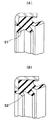
すなわち先ず、一方の給脂無しのタイプ(無給脂タイプ)のジョイントに装着使用される密封装置は、図4(A)に示すように、グリースリップ51が内向き形状とされている。これは、無給脂のため、給脂圧力によるリップのめくれ(反転)が発生しないことから、グリースリップ51として密封性能が比較的高い内向きリップを使用することができるものである。
【0004】
また、他方の給脂有りのタイプ(給脂タイプ)のジョイントに装着使用される密封装置は、図4(B)に示すように、グリースリップ52が外向き形状とされている。これは、内向きリップでは給脂圧力によるリップのめくれが発生して密封作用を維持することができなくなるため、内向きリップを使用することができないことから、次善の策として密封性能が比較的低い外向きリップを使用するものである。
【0005】
したがって、上記従来技術によると、ジョイントが給脂タイプである場合にグリースリップとして密封性能が比較的低い外向きリップを使用しなければならないために、グリースに対する密封性能が不十分となる場合があると云う不都合がある。
【0006】
【発明が解決しようとする課題】
本発明は以上の点に鑑みて、ジョイント等の装置が給脂タイプである場合にグリースリップとして密封性能が比較的高い内向きリップを使用してもリップにめくれが発生することがなく、もって密封性能を高めることが可能な密封装置を提供することを目的とする。
【0007】
【課題を解決するための手段】
上記目的を達成するため、本発明の請求項1による密封装置は、ハウジングおよび軸間の密封空間にグリースを供給する装置に装着される密封装置であって、前記ハウジングの内周側に圧入される筒状部およびフランジ部を一体成形した取付環と、前記取付環に加硫接着されたゴム状弾性材製の弾性体よりなり、前記軸に摺動自在に密接し、前記グリースの外部漏洩を阻止する内向き形状のグリースリップと、前記取付環のフランジ部および前記取付環に加硫接着されたゴム状弾性材製の弾性体よりなり、前記ハウジングの端面の外側に配置されるハウジング端面接触部と、前記取付環の筒状部の外周面に設けられた溝状のグリース給脂圧力の逃がし流路と、前記ハウジングの端面と前記ハウジング端面接触部との間に設けられる前記逃がし流路の延長路と、前記ハウジング端面接触部の弾性体により成形され、前記ハウジングの端面に密接し、前記給脂圧力により開弁して前記給脂圧力を開放する外向き形状の圧力逃がしリップとを有することを特徴とするものである。
【0008】
また、本発明の請求項2による密封装置は、ハウジングおよび軸間の密封空間にグリースを供給する装置に装着される密封装置であって、前記ハウジングの内周側に圧入される筒状部およびフランジ部を一体成形した取付環と、前記取付環に加硫接着されたゴム状弾性材製の弾性体よりなり、前記軸に摺動自在に密接し、外部の泥水やダスト等の異物が前記密封空間に侵入するのを阻止する外向き形状の主リップと、前記取付環に加硫接着されたゴム状弾性材製の弾性体よりなり、前記主リップの内側において前記軸に摺動自在に密接し、前記グリースの外部漏洩を阻止する内向き形状のグリースリップと、前記取付環のフランジ部および前記取付環に加硫接着されたゴム状弾性材製の弾性体よりなり、前記ハウジングの端面の外側に配置されるハウジング端面接触部と、前記取付環の筒状部の外周面に設けられた溝状のグリース給脂圧力の逃がし流路と、前記ハウジングの端面と前記ハウジング端面接触部との間に設けられる前記逃がし流路の延長路と、前記ハウジング端面接触部の弾性体により成形され、前記ハウジングの端面に密接し、前記給脂圧力により開弁して前記給脂圧力を開放する外向き形状の圧力逃がしリップと、前記軸に取り付けられ、前記ハウジングとの間にラビリンスシール構造を形成するスリンガーと、前記ハウジング端面接触部の弾性体により成形され、前記スリンガーの円筒部内周面に摺動自在に密接する円筒当てリップとを有することを特徴とするものである。
【0009】
また、本発明の請求項3による密封装置は、上記した請求項1または2の密封装置において、装置が具体的にはユニバーサルジョイントであることを特徴とするものである。
【0010】
上記構成を備えた本発明の請求項1による密封装置がグリース給脂タイプの装置に装着使用されると、グリース給脂時に発生する給脂圧力が、取付環の筒状部の外周面に設けられた溝状の逃がし流路から、ハウジングの端面とハウジング端面接触部との間に設けられる逃がし流路の延長路を介して圧力逃がしリップに達し、このリップを開弁させて開放されることになる。したがって、給脂圧力が外部に開放されてグリースリップにめくれを発生させることがないために、グリースリップとして密封性能が比較的高い内向き形状のリップを使用することが可能となる。
【0011】
また、上記構成を備えた本発明の請求項2による密封装置がグリース給脂タイプの装置に装着使用されると、やはりグリース給脂時に発生する給脂圧力が、取付環の筒状部の外周面に設けられた溝状の逃がし流路から、ハウジングの端面とハウジング端面接触部との間に設けられる逃がし流路の延長路を介して圧力逃がしリップに達し、このリップを開弁させて開放されることになる。したがって、給脂圧力が外部に開放されてグリースリップにめくれを発生させることがないために、グリースリップとして密封性能が比較的高い内向き形状のリップを使用することが可能となる。またこれに加えて、この請求項2の密封装置によると、主リップとともにラビリンスシール構造および円筒当てリップシール構造が設けられているために、密封性能、特に耐泥水性を一層向上させることが可能となる。
【0012】
上記構成を備えた本発明の密封装置は、ユニバーサルジョイントに利用されるのが好適であるが(請求項3)、その他の装置に対しても利用することが可能である。ハウジングにはその名称にかかわらず、密封装置を取り付けることのできる全ての部品が含まれ、また、軸にはその名称にかかわらず、リップと摺動することのできる全ての部品が含まれる。
【0013】
【発明の実施の形態】
本発明の実施形態は、以下のとおりである。
【0014】
すなわち先ず、取付環(シール金属環部)に圧力逃がし流路(溝)を設け、更にハウジング(相手ハウジング)との端面接触部に圧力逃がしリップ(ゴムリップ)を設けることにより、グリース給脂時のみ圧力を逃がし、他の時は外部からのダスト等の侵入を防ぐ構造とする。また、グリースリップについては、内向き形状(無給脂タイプのリップ形状)に変更する。
【0015】
取付環の形状については、どのような形状(等配溝または花びら環等)でも良いが、使用時に当該密封装置(シール)がハウジングから抜けない程度の離脱力は有していなければならない。外周ゴムタイプではシール抜けが懸念されるために、外周は金属環を使用すると良い。圧力逃がしリップは摺動しないため、摩耗することもなく、給脂時の内圧発生時のみ開く程度の押し付け力を有していればどのような形状でも良い。ここで、圧力逃がしリップの押し付け力はシール打ち込み位置により大きく影響を受けることから、ハウジングとの端面接触部に等配の突起を設けることにより、打ち込み高さのズレを抑え、圧力逃がしリップの押し付け力を安定させる構造とする。
【0016】
また、軸に嵌合したスリンガーは、ハウジングを少し覆う位置までとし、ラビリンス構造を形成させる。更に、シール側には、スリンガーにラジアル方向で接触するリップを設ける。このリップは従来デフサイド等に採用されている円筒当てタイプのリップ形状とする。
【0017】
上記構成によれば、給脂時に圧力を逃がすことができるため、グリースリップの向きを内側向きにすることができ、シール性(グリース保持性、耐グリースリーク性)が向上する。また、スリンガーとハウジングをラビリンス構造にすることおよびスリンガーに接触するリップ(円筒当てリップ)を付加することにより耐泥水性、耐グリースリーク性の更なる向上が可能である。
【0018】
【実施例】
つぎに本発明の実施例を図面にしたがって説明する。
【0019】
図1は、本発明の実施例に係る密封装置1を給脂タイプのユニバーサルジョイント21に装着した状態の要部断面を示している。また、図2は当該密封装置1の図1におけるA方向矢視図である。
【0020】
当該密封装置1は以下のように構成されている。
【0021】
すなわち先ず、ハウジング22の内周に嵌合される金属等剛材製の取付環2が設けられており、この取付環2にゴム状弾性材製の弾性体3が加硫接着されており、この弾性体3に複数のリップが一体成形されており、この複数のリップが、取付環2の内周側に設けられ、軸23の周面に摺動自在に密接し、外部の泥水やダスト等の異物がハウジング22および軸23間の密封空間24に侵入するのを阻止する外向き形状の主リップ4および副リップ5と、この主リップ4および副リップ5の内側に設けられ、軸23の周面に摺動自在に密接し、密封空間24に供給されるグリースが外部に漏洩するのを阻止する内向き形状のグリースリップ6と、当該密封装置1のハウジング端面接触部7の弾性体3に一体成形され、ハウジング端面22aに接離自在に密接し、給脂圧力により開弁して給脂圧力の余剰分を開放する外向き形状の圧力逃がしリップ8とによって構成されている。取付環2には、ハウジング22の内周側に圧入される筒状部2aと、ハウジング端面22aの外側に配置されて端面接触部7の一部をなすフランジ部2bとが一体成形されている。
【0022】
取付環2の筒状部2aの外周面には、密封空間24内の給脂圧力を逃がすために、溝状の圧力逃がし流路9が軸方向に沿って複数等配状に設けられている。また、端面接触部7の弾性体3には、当該密封装置1をハウジング22に対して軸方向一方から圧入したときにハウジング端面22aに当接することによって圧入位置(深さ)を特定し、かつハウジング端面22aと端面接触部7との間に圧力逃がし流路9の延長路10を確保するために、突起11が軸方向に向けて複数等配状(4〜6等配以上が好適)に設けても良い。延長路10は、圧力逃がし流路9および圧力逃がしリップ8間に配置されて両者8,9を連通させるものであって、この延長路10が設けられることにより、密封空間24内の圧力が給脂圧力により高くなりながら圧力逃がしリップ8に達し、ある一定の圧力になるとリップ8を開弁させて、内部圧力を外部に開放する。そうすることにより、内部圧力の高圧化によって給脂が困難になることを防ぐことができる。前記突起11を位置決めとして利用する際には、その高さの高低を前記リップ8の開弁圧力調整として利用することもできる。
【0023】
また、当該密封装置1には、軸23の外周に嵌着される環状のスリンガー12が設けられており、また、このスリンガー12に摺動自在に密接する円筒当てリップ13が設けられている。
【0024】
このうち、前者のスリンガー12は、その外周筒部12aの先端12bをハウジング22の外周側に位置させて、この外周筒部12aの先端12b内周面とハウジング22の外周面との間に微小な間隙14を形成することにより、ラビリンスシール構造15を形成している。ハウジング22との間隙14の形成の仕方については、図3に示すように、ハウジング22の外周縁部に環状の凹段部25を設けてこの凹段部25に外周筒部12aの先端12bが収められるような構造であっても良く、この場合には、間隙14が径方向部分と軸方向部分とを有する断面L字形に形成されることになる。
【0025】
また、後者の円筒当てリップ13は、端面接触部7の弾性体3の背面側にラッパ状に拡がる比較的大きなリップとして一体成形されており、スリンガー12の外周筒部12aの内周面に対して摺動自在に密接している。
【0026】
上記構成の密封装置1は、先ず、主リップ4および副リップ5において外部の泥水やダスト等の異物が密封空間24に侵入するのを阻止し、更にその手前側にラビリンスシール構造15および円筒当てリップ13が直列的に設けられているために、外部の異物を一層有効にシールすることができる。
【0027】
また、密封空間24内のグリースが外部へ漏洩するのをグリースリップ6によってシールするが、このグリースリップ6が密封性能の比較的高い内向き形状のリップとされているために、グリースを有効にシールすることができる。ユニバーサルジョイント21が給脂タイプであるにもかかわらず、このようにグリースリップ6として内向き形状のリップを利用できるのは、上記したようにグリース給脂時に発生する給脂圧力の余剰分を逃がし流路9および延長路10を経由して圧力逃がしリップ8から開放し、よってグリースリップ6にめくれを発生させることがないからである。
【0028】
尚、圧力逃がしリップ8は、圧力開放時以外のときは閉弁しており、よってこのリップシール部から外部の異物が侵入することはない。
【0029】
【発明の効果】
本発明は、以下の効果を奏する。
【0030】
すなわち、上記構成を備えた本発明の請求項1による密封装置においては、当該密封装置がグリース給脂タイプの装置に装着使用されると、グリース給脂時に発生する給脂圧力が、取付環の筒状部の外周面に設けられた溝状の逃がし流路から、ハウジングの端面とハウジング端面接触部との間に設けられる逃がし流路の延長路を介して圧力逃がしリップに達し、このリップを開弁させて開放されるために、給脂圧力によってグリースリップにめくれが発生するのを防止することができる。したがってこれに伴って、装置が給脂タイプであってもグリースリップとして密封性能が比較的高い内向きリップを使用することが可能となるために、密封性能を向上させることができる。
【0031】
また、上記構成を備えた本発明の請求項2による密封装置においては、当該密封装置がグリース給脂タイプの装置に装着使用されると、やはりグリース給脂時に発生する給脂圧力が、取付環の筒状部の外周面に設けられた溝状の逃がし流路から、ハウジングの端面とハウジング端面接触部との間に設けられる逃がし流路の延長路を介して圧力逃がしリップに達し、このリップを開弁させて開放されるために、給脂圧力によってグリースリップにめくれが発生するのを防止することができる。したがってこれに伴って、装置が給脂タイプであってもグリースリップとして密封性能が比較的高い内向きリップを使用することが可能となるために、密封性能を向上させることができる。またこれに加えて、この請求項2の密封装置においては、主リップとともにラビリンスシール構造および円筒当てリップシール構造が設けられているために、密封性能、特に耐泥水性を一層向上させることができる。
【0032】
また、上記構成を備えた本発明の請求項3による密封装置においては、ユニバーサルジョイントを製品として上記効果を得ることができ、ユニバーサルジョイントの品質を向上させることができる。
【図面の簡単な説明】
【図1】本発明の実施例に係る密封装置の要部断面図
【図2】同密封装置の図1におけるA方向矢視図
【図3】本発明の他の実施例に係る密封装置の要部断面図
【図4】(A)および(B)とも従来例に係る密封装置の要部断面図
【符号の説明】
1 密封装置
2 取付環
2a 筒状部
2b フランジ部
3 弾性体
4 主リップ
5 副リップ
6 グリースリップ
7 ハウジング端面接触部
8 圧力逃がしリップ
9 圧力逃がし流路
10 延長路
11 突起
12 スリンガー
12a 外周筒部(円筒部)
12b 先端
13 円筒当てリップ
14 間隙
15 ラビリンスシール構造
21 ユニバーサルジョイント(装置)
22 ハウジング
23 軸
24 密封空間
25 凹段部[0001]
BACKGROUND OF THE INVENTION
The present invention relates to a sealing device, and more particularly to a sealing device mounted on a device that supplies grease to a sealed space between a housing and a shaft. The device is, for example, a universal joint in a propeller shaft of an automobile drive system.
[0002]
[Prior art]
In the universal joint of the propeller shaft, the grease lip shape of the sealing device mounted and used on this joint varies depending on whether or not the lubricating grease is supplied.
[0003]
That is, first, as shown in FIG. 4 (A), the
[0004]
Moreover, as shown in FIG. 4 (B), the
[0005]
Therefore, according to the above prior art, when the joint is of a greasing type, an outward lip having a relatively low sealing performance must be used as the grease lip, so that the sealing performance against grease may be insufficient. There is an inconvenience.
[0006]
[Problems to be solved by the invention]
In view of the above points, the present invention does not cause turning of the lip even when an inward lip having a relatively high sealing performance is used as a grease lip when a device such as a joint is a greasing type. It aims at providing the sealing device which can improve sealing performance.
[0007]
[Means for Solving the Problems]
In order to achieve the above object, a sealing device according to
[0008]
A sealing device according to
[0009]
The sealing device according to claim 3 of the present invention is the sealing device according to
[0010]
When the sealing device according to the first aspect of the present invention having the above configuration is mounted and used in a grease supply type device, a grease supply pressure generated during grease supply is provided on the outer peripheral surface of the cylindrical portion of the mounting ring. The pressure relief lip is reached from the groove-shaped relief passage formed through the extension passage of the relief passage provided between the housing end face and the housing end face contact portion, and the lip is opened to be opened. become. Therefore, since the grease supply pressure is not released to the outside and the grease lip is not turned over, it is possible to use an inwardly shaped lip having a relatively high sealing performance as the grease lip.
[0011]
Further, when the sealing device according to
[0012]
The sealing device of the present invention having the above configuration is preferably used for a universal joint (Claim 3), but can also be used for other devices. The housing includes all parts that can be fitted with the sealing device regardless of its name, and the shaft includes all parts that can slide with the lip regardless of its name.
[0013]
DETAILED DESCRIPTION OF THE INVENTION
Embodiments of the present invention are as follows.
[0014]
That is, first, by providing a pressure relief channel (groove) in the mounting ring (seal metal ring part) and further providing a pressure relief lip (rubber lip) at the end surface contact part with the housing (mating housing), only when grease is supplied The structure is designed to release pressure and prevent dust from entering from outside at other times. In addition, the grease lip is changed to an inward shape (grease-free lip shape).
[0015]
The shape of the mounting ring may be any shape (such as a uniform groove or a petal ring), but it must have such a detaching force that the sealing device (seal) does not come out of the housing during use. Since there is a concern about the omission of the seal in the outer peripheral rubber type, it is preferable to use a metal ring for the outer periphery. Since the pressure relief lip does not slide, it does not wear and may have any shape as long as it has a pressing force that opens only when an internal pressure is generated during lubrication. Here, the pressing force of the pressure relief lip is greatly influenced by the seal driving position, so by providing evenly spaced protrusions at the end surface contact with the housing, the displacement of the driving height is suppressed and the pressure releasing lip is pressed. A structure that stabilizes the force.
[0016]
Further, the slinger fitted to the shaft extends to a position that slightly covers the housing to form a labyrinth structure. Further, on the seal side, a lip that is in radial contact with the slinger is provided. This lip has a cylindrical lip type lip shape which is conventionally used for a differential side or the like.
[0017]
According to the above configuration, since the pressure can be released at the time of lubrication, the direction of the grease lip can be directed inward, and the sealing performance (grease retention and grease leak resistance) is improved. Further, by making the slinger and the housing into a labyrinth structure and adding a lip (cylindrical abutment lip) that contacts the slinger, the muddy water resistance and the grease leak resistance can be further improved.
[0018]
【Example】
Next, embodiments of the present invention will be described with reference to the drawings.
[0019]
FIG. 1 shows a cross-section of the main part in a state where the
[0020]
The
[0021]
That is, first, a mounting
[0022]
On the outer peripheral surface of the
[0023]
Further, the
[0024]
Among these, the
[0025]
The latter
[0026]
The
[0027]
Further, the
[0028]
The
[0029]
【The invention's effect】
The present invention has the following effects.
[0030]
That is, in the sealing device according to the first aspect of the present invention having the above-described configuration, when the sealing device is mounted and used in a grease lubrication type device, the grease supply pressure generated during grease lubrication is reduced. A pressure relief lip is reached from a groove-like escape passage provided on the outer peripheral surface of the cylindrical portion via an extension passage of the escape passage provided between the housing end surface and the housing end surface contact portion. Since the valve is opened for opening, it is possible to prevent the grease lip from being turned up by the grease supply pressure. Therefore, along with this, even if the apparatus is a greasing type, it is possible to use an inward lip having a relatively high sealing performance as a grease lip, so that the sealing performance can be improved.
[0031]
Further, in the sealing device according to
[0032]
In the sealing device according to the third aspect of the present invention having the above-described configuration, the above-described effects can be obtained using the universal joint as a product, and the quality of the universal joint can be improved.
[Brief description of the drawings]
FIG. 1 is a cross-sectional view of a main part of a sealing device according to an embodiment of the present invention. FIG. 2 is a view taken along the direction A in FIG. Cross-sectional view of essential parts [FIG. 4] (A) and (B) are cross-sectional views of essential parts of the sealing device according to the conventional example [Explanation of symbols]
DESCRIPTION OF
22
Claims (3)
前記ハウジング(22)の内周側に圧入される筒状部(2a)およびフランジ部(2b)を一体成形した取付環(2)と、
前記取付環(2)に加硫接着されたゴム状弾性材製の弾性体(3)よりなり、前記軸(23)に摺動自在に密接し、前記グリースの外部漏洩を阻止する内向き形状のグリースリップ(6)と、
前記取付環(2)のフランジ部(2b)および前記取付環(2)に加硫接着されたゴム状弾性材製の弾性体(3)よりなり、前記ハウジング(22)の端面(22a)の外側に配置されるハウジング端面接触部(7)と、
前記取付環(2)の筒状部(2a)の外周面に設けられた溝状のグリース給脂圧力の逃がし流路(9)と、
前記ハウジング(22)の端面(22a)と前記ハウジング端面接触部(7)との間に設けられる前記逃がし流路(9)の延長路(10)と、
前記ハウジング端面接触部(7)の弾性体(3)により成形され、前記ハウジング(22)の端面(22a)に密接し、前記給脂圧力により開弁して前記給脂圧力を開放する外向き形状の圧力逃がしリップ(8)とを有することを特徴とする密封装置。A sealing device (1) mounted on a device (21) for supplying grease to a sealed space (24) between a housing (22) and a shaft (23),
A mounting ring (2) integrally formed with a cylindrical part (2a) and a flange part (2b) which are press-fitted into the inner peripheral side of the housing (22);
An inward shape formed of an elastic body (3) made of a rubber-like elastic material vulcanized and bonded to the mounting ring (2), and slidably in close contact with the shaft (23) to prevent external leakage of the grease Grease lip (6),
The flange portion (2b) of the mounting ring (2) and an elastic body (3) made of a rubber-like elastic material vulcanized and bonded to the mounting ring (2), the end surface (22a) of the housing (22) A housing end surface contact portion (7) disposed on the outside;
A groove-shaped grease supply pressure relief passage (9) provided on the outer peripheral surface of the cylindrical portion (2a) of the mounting ring (2) ;
An extension path (10) of the escape passage (9) provided between the end face (22a) of the housing (22) and the housing end face contact portion (7);
An outward direction which is formed by the elastic body (3) of the housing end surface contact portion (7), is in close contact with the end surface (22a) of the housing (22), and is opened by the greasing pressure to release the greasing pressure. Sealing device characterized by having a pressure relief lip (8) in the shape.
前記ハウジング(22)の内周側に圧入される筒状部(2a)およびフランジ部(2b)を一体成形した取付環(2)と、
前記取付環(2)に加硫接着されたゴム状弾性材製の弾性体(3)よりなり、前記軸(23)に摺動自在に密接し、外部の泥水やダスト等の異物が前記密封空間(24)に侵入するのを阻止する外向き形状の主リップ(4)と、
前記取付環(2)に加硫接着されたゴム状弾性材製の弾性体(3)よりなり、前記主リップ(4)の内側において前記軸(23)に摺動自在に密接し、前記グリースの外部漏洩を阻止する内向き形状のグリースリップ(6)と、
前記取付環(2)のフランジ部(2b)および前記取付環(2)に加硫接着されたゴム状弾性材製の弾性体(3)よりなり、前記ハウジング(22)の端面(22a)の外側に配置されるハウジング端面接触部(7)と、
前記取付環(2)の筒状部(2a)の外周面に設けられた溝状のグリース給脂圧力の逃がし流路(9)と、
前記ハウジング(22)の端面(22a)と前記ハウジング端面接触部(7)との間に設けられる前記逃がし流路(9)の延長路(10)と、
前記ハウジング端面接触部(7)の弾性体(3)により成形され、前記ハウジング(22)の端面(22a)に密接し、前記給脂圧力により開弁して前記給脂圧力を開放する外向き形状の圧力逃がしリップ(8)と、
前記軸(23)に取り付けられ、前記ハウジング(22)との間にラビリンスシール構造(15)を形成するスリンガー(12)と、
前記ハウジング端面接触部(7)の弾性体(3)により成形され、前記スリンガー(12)の円筒部(12a)内周面に摺動自在に密接する円筒当てリップ(13)とを有することを特徴とする密封装置。A sealing device (1) mounted on a device (21) for supplying grease to a sealed space (24) between a housing (22) and a shaft (23),
A mounting ring (2) integrally formed with a cylindrical part (2a) and a flange part (2b) which are press-fitted into the inner peripheral side of the housing (22);
It consists of an elastic body (3) made of rubber-like elastic material that is vulcanized and bonded to the mounting ring (2), and is slidably in close contact with the shaft (23), so that foreign matters such as external muddy water and dust are sealed. An outwardly shaped main lip (4) that prevents entry into the space (24);
The elastic body (3) made of a rubber-like elastic material bonded to the mounting ring (2) by vulcanization , is slidably in close contact with the shaft (23) inside the main lip (4), and the grease An inwardly-shaped grease lip (6) that prevents external leakage of
The flange portion (2b) of the mounting ring (2) and an elastic body (3) made of a rubber-like elastic material vulcanized and bonded to the mounting ring (2), the end surface (22a) of the housing (22) A housing end surface contact portion (7) disposed on the outside;
A groove-shaped grease supply pressure relief passage (9) provided on the outer peripheral surface of the cylindrical portion (2a) of the mounting ring (2) ;
An extension path (10) of the escape passage (9) provided between the end face (22a) of the housing (22) and the housing end face contact portion (7);
An outward direction which is formed by the elastic body (3) of the housing end surface contact portion (7), is in close contact with the end surface (22a) of the housing (22), and is opened by the greasing pressure to release the greasing pressure. Shaped pressure relief lip (8);
A slinger (12) attached to the shaft (23) and forming a labyrinth seal structure (15) with the housing (22);
A cylindrical abutment lip (13) formed by an elastic body (3) of the housing end surface contact portion (7) and slidably in close contact with the inner peripheral surface of the cylindrical portion (12a) of the slinger (12); Sealing device characterized.
装置(21)が具体的にはユニバーサルジョイントであることを特徴とする密封装置。The sealing device according to claim 1 or 2,
A sealing device, characterized in that the device (21) is specifically a universal joint.
Priority Applications (1)
| Application Number | Priority Date | Filing Date | Title |
|---|---|---|---|
| JP2002061262A JP3965559B2 (en) | 2002-03-07 | 2002-03-07 | Sealing device |
Applications Claiming Priority (1)
| Application Number | Priority Date | Filing Date | Title |
|---|---|---|---|
| JP2002061262A JP3965559B2 (en) | 2002-03-07 | 2002-03-07 | Sealing device |
Publications (2)
| Publication Number | Publication Date |
|---|---|
| JP2003254442A JP2003254442A (en) | 2003-09-10 |
| JP3965559B2 true JP3965559B2 (en) | 2007-08-29 |
Family
ID=28670255
Family Applications (1)
| Application Number | Title | Priority Date | Filing Date |
|---|---|---|---|
| JP2002061262A Expired - Lifetime JP3965559B2 (en) | 2002-03-07 | 2002-03-07 | Sealing device |
Country Status (1)
| Country | Link |
|---|---|
| JP (1) | JP3965559B2 (en) |
Families Citing this family (7)
| Publication number | Priority date | Publication date | Assignee | Title |
|---|---|---|---|---|
| JP4545468B2 (en) * | 2004-03-26 | 2010-09-15 | 光洋シーリングテクノ株式会社 | Sealing device |
| KR101189841B1 (en) | 2004-06-11 | 2012-10-10 | 엔오케이 가부시키가이샤 | Sealing device |
| JP4639651B2 (en) * | 2004-06-11 | 2011-02-23 | Nok株式会社 | Sealing device |
| JP2006083880A (en) * | 2004-09-14 | 2006-03-30 | Kawasaki Heavy Ind Ltd | Power transmission shaft seal structure |
| JP5479771B2 (en) * | 2009-04-28 | 2014-04-23 | 光洋シーリングテクノ株式会社 | Sealing device |
| JP6868983B2 (en) * | 2016-08-23 | 2021-05-12 | Nok株式会社 | Sealing device |
| US10955005B2 (en) * | 2017-06-19 | 2021-03-23 | Neapco Intellectual Property Holdings, Llc | Cardan universal joint seal with radially extending lips |
-
2002
- 2002-03-07 JP JP2002061262A patent/JP3965559B2/en not_active Expired - Lifetime
Also Published As
| Publication number | Publication date |
|---|---|
| JP2003254442A (en) | 2003-09-10 |
Similar Documents
| Publication | Publication Date | Title |
|---|---|---|
| US7658386B2 (en) | Retrofittable severe duty seal for a shaft | |
| US6726212B2 (en) | Retrofittable severe duty seal for a shaft | |
| US4252329A (en) | Semi-unitized shaft seal | |
| US6029980A (en) | Fluid side contamination exclusion sealing lip for radial shaft seals | |
| US5687972A (en) | Unitary oil seal assembly | |
| US4049281A (en) | Unitized dual lip seal method | |
| WO2009130933A1 (en) | Sealing device | |
| JPWO2009078314A1 (en) | Sealing device | |
| CN101688611A (en) | Sealing device | |
| US5613691A (en) | Sealing device for universal joint with integral sealing lips and cover portion | |
| JP3965559B2 (en) | Sealing device | |
| US6464228B1 (en) | Method of using a retrofittable severe duty seal for a shaft | |
| JPH0530638U (en) | Sealing device | |
| JP2605197Y2 (en) | Sealing device | |
| JP3738509B2 (en) | Sealing device | |
| JP4685248B2 (en) | Oil seal | |
| JP3138507U (en) | Sealing device | |
| US4418920A (en) | Fluid seal for engine crankshaft applications | |
| JP2003097716A (en) | Sealing device for axle | |
| JP4853665B2 (en) | Center bearing support | |
| JP2003106464A (en) | Hermetically sealed device | |
| JP4265579B2 (en) | Sealing device | |
| JP2005265079A (en) | Sealing device | |
| JPH0590045U (en) | Sealing device | |
| JPH071553Y2 (en) | Integrated combination seal |
Legal Events
| Date | Code | Title | Description |
|---|---|---|---|
| A621 | Written request for application examination |
Free format text: JAPANESE INTERMEDIATE CODE: A621 Effective date: 20041014 |
|
| A977 | Report on retrieval |
Free format text: JAPANESE INTERMEDIATE CODE: A971007 Effective date: 20061110 |
|
| A131 | Notification of reasons for refusal |
Free format text: JAPANESE INTERMEDIATE CODE: A131 Effective date: 20061115 |
|
| A521 | Request for written amendment filed |
Free format text: JAPANESE INTERMEDIATE CODE: A523 Effective date: 20061226 |
|
| TRDD | Decision of grant or rejection written | ||
| A01 | Written decision to grant a patent or to grant a registration (utility model) |
Free format text: JAPANESE INTERMEDIATE CODE: A01 Effective date: 20070502 |
|
| A61 | First payment of annual fees (during grant procedure) |
Free format text: JAPANESE INTERMEDIATE CODE: A61 Effective date: 20070515 |
|
| R150 | Certificate of patent or registration of utility model |
Free format text: JAPANESE INTERMEDIATE CODE: R150 Ref document number: 3965559 Country of ref document: JP Free format text: JAPANESE INTERMEDIATE CODE: R150 |
|
| FPAY | Renewal fee payment (event date is renewal date of database) |
Free format text: PAYMENT UNTIL: 20100608 Year of fee payment: 3 |
|
| FPAY | Renewal fee payment (event date is renewal date of database) |
Free format text: PAYMENT UNTIL: 20110608 Year of fee payment: 4 |
|
| FPAY | Renewal fee payment (event date is renewal date of database) |
Free format text: PAYMENT UNTIL: 20120608 Year of fee payment: 5 |
|
| FPAY | Renewal fee payment (event date is renewal date of database) |
Free format text: PAYMENT UNTIL: 20120608 Year of fee payment: 5 |
|
| FPAY | Renewal fee payment (event date is renewal date of database) |
Free format text: PAYMENT UNTIL: 20130608 Year of fee payment: 6 |
|
| R250 | Receipt of annual fees |
Free format text: JAPANESE INTERMEDIATE CODE: R250 |
|
| EXPY | Cancellation because of completion of term |