JP3965247B2 - 畦 coating machine - Google Patents
畦 coating machine Download PDFInfo
- Publication number
- JP3965247B2 JP3965247B2 JP21713898A JP21713898A JP3965247B2 JP 3965247 B2 JP3965247 B2 JP 3965247B2 JP 21713898 A JP21713898 A JP 21713898A JP 21713898 A JP21713898 A JP 21713898A JP 3965247 B2 JP3965247 B2 JP 3965247B2
- Authority
- JP
- Japan
- Prior art keywords
- trimming
- pretreatment
- cylinder
- rod
- drum
- Prior art date
- Legal status (The legal status is an assumption and is not a legal conclusion. Google has not performed a legal analysis and makes no representation as to the accuracy of the status listed.)
- Expired - Fee Related
Links
Images


Landscapes
- Soil Working Implements (AREA)
Description
【0001】
【発明の属する技術分野】
本発明は、走行機体の後部に装着され、該走行機体から動力を受けて駆動する整畦体及び前処理体を備えた畦塗り機に関し、特に整畦体及び前処理体をオフセット可能に取付けたものに関する。
【0002】
【従来の技術】
従来、走行機体の後部に装着され、該走行機体から動力を受け、元畦及び圃場を耕耘して畦状に盛り上げる前処理体、及びこの前処理体により耕耘された土壌を回転しながら畦に成形するドラム状の整畦体を備え、本体に対して前処理体及び整畦体を左右にオフセット可能に構成した畦塗り機が周知である。
【0003】
上記本体に対して前処理体及び整畦体を左右にオフセットする構成としては各種のものが考えられるが、例えば、前処理体及び整畦体のオフセット量を調節する手段として手動式のシリンダ機構を用いることが、従来から一般に知られている。
【0004】
【発明が解決しようとする課題】
上記手動式のシリンダ機構においては、シリンダ機構のシリンダに嵌挿されるロッドを移動させて、シリンダとロッドにロック用のピンを挿通して固定し、前処理体及び整畦体のオフセット量を調節するようにしているが、ロック用のピンは剛体のため、シリンダとロッドの加工精度が悪いと、シリンダとロッドの挿通孔が互いに合い難く、操作が面倒であった。また、シリンダとロッドとの間にガタつきを生じ、騒音を発したり、ロッドやピンを損傷することがあった。本発明は、このような問題点を解決することを目的になされたものである。
【0005】
【課題を解決するための手段】
上記の目的を達成するために本発明は、走行機体の後部に装着され、該走行機体から動力を受け、元畦及び圃場を耕耘して畦状に盛り上げる前処理体、及びこの前処理体により耕耘された土壌を回転しながら畦に成形するドラム状の整畦体を備え、本体に対して前処理体及び整畦体を左右にオフセット可能に構成した畦塗り機において、
本体に対して平行リンクを介して前処理体及び整畦体の支持フレームを左右方向に移動可能に支持し、該支持フレームと平行リンクの一方との間にシリンダ機構を設けて前処理体及び整畦体のオフセット量を調節可能とし、シリンダ機構のシリンダに嵌挿されるロッドの先端部に弾力のあるクッション部材を設けたことを特徴としている。
【0006】
【作用】
上記の構成により本発明の畦塗り機は、前処理体及び整畦体のオフセット量を調節するとき、ロック用ピンを抜き取ってシリンダに対してロッドを移動させ、シリンダとロッドの挿通孔にロック用ピンを挿通する際のシリンダとロッドの挿通孔の孔合わせが、ロッドがクッション部材によりわずかに移動することで容易に行われ、短時間で操作ができる。また、ロッドはクッション部材を介してシリンダと接するので、緩衝作用が働いて騒音を発したり、ロッドやピンを損傷することがない。
【0007】
【発明の実施の形態】
以下、本発明の実施の形態を添付の図面を参照して具体的に説明する。
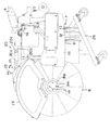
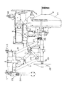
図1ないし図3において、符号1は図示しないトラクタの後部に設けられたトップリンク及びロアリンクからなる三点リンク連結機構に連結されて、整畦作業を行う畦塗り機である。この畦塗り機1は、伝動フレームを兼ねる本体フレーム2を、機体の進行方向と直交するようにして設けている。この本体フレーム2には、前端部から前方に向け突出し、トラクタのPTO軸からユニバーサルジョイント及び伝動軸を介して動力を受ける入力軸3を設け、また、上方に突出するトップリンク連結部4を設けると共に、左右にロアリンク連結部5,5を設け、トラクタの三点リンク連結機構に連結するようにしている。
【0008】
元畦及び圃場を耕耘して畦状に盛り上げるロータリ耕耘装置からなる前処理体7、及びこの前処理体7の後方に、前処理体7により耕耘された土壌を畦に成形する多角円錐状ドラムからなる整畦体8が、伝動フレーム2にオフセット用平行リンク9を介して支持され、伝動・支持フレーム10と一体的に連繋された伝動・支持フレーム6により連結支持されている。そして、トラクタから入力軸3に受けた動力は、本体フレーム2からWジョイント(広角ジョイント)付きのスプライン伝動軸11−伝動・支持フレーム10−伝動・支持フレーム6を介して前処理体7及び整畦体8に伝達され、それぞれ所定方向に回転させて作業を行うようにしている。
【0009】
前処理体7は、その回転軸12の軸心を機体の進行方向と平行に配設し、この回転軸12の軸周に複数の耕耘爪13を取付けて、元畦の一部及び圃場を耕耘して元畦に対して畦状に盛り上げるようにしている。前処理体7により畦状に盛り上げられた土壌は整畦体8が回転しながら畦状に成形する。整畦体8には上下調整装置15が設けられていて、上下調節が可能である。
【0010】
前処理体7はカバー16により覆われており、このカバー16は左右調整装置14により左右にスライド可能である。また、前処理体7の外側部はサイドカバー17により覆われるが、このサイドカバー17は自動的に上下動するように支持されている。また、サイドカバー17の下部にはゴム板のような弾性板が取付けられていて、畦土に接したとき弾性変形し、復帰するフレキシブルな構造となっている。
【0011】
上記整畦体8は、伝動フレーム6a終端部から機体側方に向け突出した図示しない回転軸に対して、その基部8aを図示しないドラムボスを介して複数(図面では4個)の固定ボルト18により取付けられる。整畦体基部8aのドラムボスへの取付け面と、ドラムボスの整畦体8を取付けるドラム取付け面とは、回転軸に対して互いに偏心して設けられている。そして、整畦体8の基部をドラムボスに対して周方向に移動させて固定ボルト18により固定することにより、整畦体8の偏心量(振れ幅)を変更可能としている。
【0012】
整畦体8は、この実施例では12角の稜線と平面部を有する多角円錐状ドラム8と、このドラム8の中心部分から水平方向に突出している水平筒状体8bとからなり、多角円錐状ドラム8が偏心回転することにより、多角の稜線と平面部が偏心しながら回転して畦法面を叩いて整畦し、水平筒状体8bにより畦頂部を平面状に成形するようにしている。
【0013】
多角円錐状ドラム8の上方は、支持フレーム10に支持されたカバー19により覆われているが、このカバー19は、整畦体8の安全に必要な部分のみを覆う大きさ、形状であり、かつ、トラクタの操縦者が円錐状ドラム8の作業状態を観察しうる状態に設けられている。そして、機体の前進と共に前処理体7により掘削された土壌を、前述のように多角円錐状ドラム8によって元畦の傾斜面に塗り付け、また、元畦の水平頂部を水平筒状体8bにより塗り付けて整畦するようにしている。
【0014】
上記支持フレーム10の左側端部と一方の平行リンク9間には、図4及び図5に詳細に示すオフセット量調節用シリンダ機構20が設けられている。このシリンダ機構20は、シリンダ20aと、ロッド20bと、ロックピン20cと、ストッパ用ピン20dと、複数のストッパ用ピン挿通孔20eからなり、ロックピン20cとストッパ用ピン20dの差替えにより、前処理体7及び整畦体8をオフセットしない図1、図2の状態から図6の最大限オフセットした状態まで、段階的に調節可能となっている。また、シリンダ20aに嵌挿されるロッド20bの先端部に弾力のあるゴムのようなクッション部材21を設けている。
【0015】
支持フレーム10の左側端部には、三角ディスク状のゲージホイール22が上下調節支持部23により上下調節可能に設けられている。また、このゲージホイール22の前側下方にはキャスタ付きスタンド24がスタンド支持部25に着脱可能に設けられている。さらに、前処理体7の外側端部下方にもスタンド26が着脱可能に設けられている。これらスタンド24,26は作業中は不要なものであり、着脱可能とするか、あるいは折り畳み可能に設けられる。
【0016】
畦塗り機1の平面視ほぼ中央部には、機体の前後水平状態を検出する前後水平水準器27と、機体の左右水平状態を検出する左右水平水準器28とが設けられ、機体の水平状態を検出して、アジャストするようにしている。
【0017】
このような構成の畦塗り機1においては、前処理体7及び整畦体8が伝動・支持フレーム6により支持され、トラクタから入力軸3に受けた動力は本体フレーム2からWジョイント(広角ジョイント)付きのスプライン伝動軸11−伝動・支持フレーム10−伝動・支持フレーム6を介して前処理体7及び整畦体8に伝達される。前処理体7では元畦の一部及び圃場を耕耘して元畦に対して畦状に盛り上げ、その耕耘された土壌を多角円錐状ドラム8の多角の稜線と平面部が偏心しながら回転して畦法面を叩いて畦に成形する。
【0018】
多角円錐状ドラム8では、その基部8aがドラムボスに対して固定ボルト18により取付けられているが、整畦体基部8aのドラムボスへの取付け面をドラムボスのドラム取付け面に対して周方向に移動させて固定ボルト18により固定することにより、整畦体8の偏心量(振れ幅)を所定範囲で(実施例では3段階に)変更することができる。
【0019】
そして、前処理体7により、元畦及び圃場が耕耘されて畦状に盛り上げる土壌の土質、水分等により、多角円錐状ドラム8の振れ幅を変更して土質や土壌水分に合った適切な整畦作業が行われる。また、圃場の形状や土壌の状態などに応じて前処理体7及び整畦体8をオフセットさせた方がよい場合には、オフセット量調節用シリンダ機構22のシリンダ22a、ロッド22b、ロックピン22c、ストッパ用ピン20dを操作してオフセット量を調節し、適切な状態で整畦作業を行うことができる。
【0020】
【発明の効果】
以上説明したように本発明の畦塗り機によれば、本体に対して平行リンクを介して前処理体及び整畦体の支持フレームを左右方向に移動可能に支持し、該支持フレームと平行リンクの一方との間にシリンダ機構を設けて前処理体及び整畦体のオフセット量を調節可能とし、シリンダ機構のシリンダに嵌挿されるロッドの先端部に弾力のあるクッション部材を設けたので、前処理体及び整畦体のオフセット量を調節するとき、ロック用ピンを抜き取ってシリンダに対してロッドを移動させ、シリンダとロッドの挿通孔にロック用ピンを挿通する際のシリンダとロッドの挿通孔の孔合わせが、ロッドがクッション部材によりわずかに移動することで容易に行うことができ、短時間で操作することができる。また、ロッドはクッション部材を介してシリンダと接しているので、緩衝作用が働いて騒音を発したり、ロッドやピンを損傷するのを防止することができる。
【図面の簡単な説明】
【図1】本発明による畦塗り機の平面図である。
【図2】同畦塗り機の背面図である。
【図3】同畦塗り機の側面図である。
【図4】シリンダ機構のロッドを伸長した状態の断面図である。
【図5】シリンダ機構のロッドを収縮した状態の断面図である。
【図6】畦塗り機の前処理体及び整畦体をオフセットした状態の平面図である。
【符号の説明】
1 畦塗り機
2 本体フレーム(伝動フレーム)
3 入力軸
4 トップリンク連結部
5 ロアリンク連結部
6 伝動・支持フレーム 6a 伝動フレーム
7 前処理体
8 整畦体(多角円錐状ドラム) 8a 整畦体の基部 8b 水平筒状体
9 オフセット用平行リンク
10 伝動・支持フレーム
11 Wジョイント(広角ジョイント)付きのスプライン伝動軸
12 回転軸
13 耕耘爪
14 左右調整装置
15 上下調整装置
16 前処理体のカバー
17 サイドカバー
18 固定ボルト
19 整畦体のカバー
20 オフセット量調節用シリンダ機構 20a シリンダ 20b ロッド
20c ロックピン 20d ストッパ用ピン 20e ストッパ用ピン挿通孔
21 クッション部材
22 ゲージホイール
23 上下調節支持部
24,26 スタンド
25 スタンド支持部
27 前後水平水準器
28 左右水平水準器[0001]
BACKGROUND OF THE INVENTION
The present invention relates to a coater equipped with a trimming body and a pretreatment body that are mounted on the rear part of a traveling machine body and driven by receiving power from the traveling machine body, and in particular, the trimming body and the pretreatment body are attached so as to be offset. About things.
[0002]
[Prior art]
Conventionally, a pre-treatment body that is attached to the rear part of a traveling machine body, receives power from the traveling machine body, cultivates the main fence and the field and raises it into a bowl shape, and the soil cultivated by this pre-treatment body while rotating the soil 2. Description of the Related Art A wrinkle coater having a drum-shaped trimming body to be molded and configured so that a pretreatment body and a trimming body can be offset left and right with respect to a main body is well known.
[0003]
Various configurations can be considered for offsetting the pretreatment body and the trimming body to the left and right with respect to the main body. For example, a manual cylinder mechanism is used as a means for adjusting the offset amount of the pretreatment body and the trimming body. It has been generally known to use.
[0004]
[Problems to be solved by the invention]
In the above-mentioned manual cylinder mechanism, the rod inserted into the cylinder of the cylinder mechanism is moved, the lock pin is inserted and fixed to the cylinder and the rod, and the offset amount of the pretreatment body and the adjusting body is adjusted. However, since the locking pin is a rigid body, if the processing accuracy of the cylinder and the rod is poor, the insertion holes of the cylinder and the rod are difficult to fit with each other, and the operation is troublesome. In addition, rattling occurs between the cylinder and the rod, generating noise and damaging the rod and pin. The present invention has been made for the purpose of solving such problems.
[0005]
[Means for Solving the Problems]
In order to achieve the above object, the present invention provides a pre-processing body that is attached to the rear part of a traveling machine body, receives power from the traveling machine body, cultivates the main fence and the field and raises it in a bowl shape, and the pre-processing body. In a basket coater comprising a drum-shaped trimming body that is formed into a kite while rotating the cultivated soil, and configured so that the pretreatment body and the trimming body can be offset left and right with respect to the main body,
A support frame of the pretreatment body and the trimming body is supported to be movable in the left-right direction via a parallel link with respect to the main body, and a cylinder mechanism is provided between the support frame and one of the parallel links, The offset amount of the trimming body can be adjusted, and a resilient cushion member is provided at the tip of the rod fitted into the cylinder of the cylinder mechanism.
[0006]
[Action]
With the above configuration, when the offset amount of the pretreatment body and the trimming body is adjusted, the brush coating machine of the present invention extracts the lock pin and moves the rod relative to the cylinder, and locks it in the cylinder and the rod insertion hole. The hole alignment of the cylinder and the rod insertion hole when inserting the pin for use is easily performed by moving the rod slightly by the cushion member, and the operation can be performed in a short time. Further, since the rod is in contact with the cylinder through the cushion member, the buffering action does not generate noise and damage the rod and the pin.
[0007]
DETAILED DESCRIPTION OF THE INVENTION
Hereinafter, embodiments of the present invention will be specifically described with reference to the accompanying drawings.
In FIG. 1 to FIG. 3, reference numeral 1 designates a wrinkle coater that is connected to a three-point link connecting mechanism including a top link and a lower link provided at the rear of a tractor (not shown) to perform a trimming operation. In this wrinkle coater 1, a main body frame 2 also serving as a transmission frame is provided so as to be orthogonal to the traveling direction of the machine body. The main body frame 2 is provided with an
[0008]
A pretreatment body 7 composed of a rotary tiller that cultivates the main fence and the field and raises it into a bowl shape , and a polygonal cone drum that forms the soil cultivated by the pretreatment body 7 into a fence behind the pretreatment body 7 Seiaze
[0009]
The pretreatment body 7 is arranged with the axis of the
[0010]
The pretreatment body 7 is covered with a
[0011]
The trimming
[0012]
In this embodiment, the trimming
[0013]
The upper part of the polygonal
[0014]
Between the left end portion of the
[0015]
A triangular disc-shaped
[0016]
A front-rear
[0017]
In the scissor coater 1 having such a configuration, the pretreatment body 7 and the trimming
[0018]
In polygonal
[0019]
Then, the pre-treatment body 7 changes the swing width of the
[0020]
【The invention's effect】
As described above, according to the plastering machine of the present invention, the support frame of the pretreatment body and the trimming body is supported so as to be movable in the left-right direction via the parallel link to the main body, and the parallel link to the support frame Since the cylinder mechanism is provided between the front end of the rod and the offset amount of the pretreatment body and the trimming body can be adjusted, and the elastic cushion member is provided at the tip of the rod inserted into the cylinder of the cylinder mechanism. When adjusting the offset amount of the processing body and trimming body, remove the lock pin, move the rod relative to the cylinder, and insert the lock pin into the cylinder and rod insertion hole. The hole alignment can be easily performed by moving the rod slightly by the cushion member, and can be operated in a short time. In addition, since the rod is in contact with the cylinder via the cushion member, it is possible to prevent the buffering action from generating noise and damaging the rod and the pin.
[Brief description of the drawings]
FIG. 1 is a plan view of a coater according to the present invention.
FIG. 2 is a rear view of the same coater.
FIG. 3 is a side view of the same wrinkle coater.
FIG. 4 is a cross-sectional view of a cylinder mechanism with a rod extended.
FIG. 5 is a sectional view of the cylinder mechanism in a contracted state.
FIG. 6 is a plan view showing a state in which the pretreatment body and the trimming body of the wrinkle coater are offset.
[Explanation of symbols]
1 Spider coater 2 Body frame (transmission frame)
3
14
Claims (1)
本体に対して平行リンクを介して前処理体及び整畦体の支持フレームを左右方向に移動可能に支持し、該支持フレームと平行リンクの一方との間にシリンダ機構を設けて前処理体及び整畦体のオフセット量を調節可能とし、シリンダ機構のシリンダに嵌挿されるロッドの先端部に弾力のあるクッション部材を設けたことを特徴とする畦塗り機。A pre-treatment body that is attached to the rear of the traveling machine body, receives power from the traveling machine body, cultivates the main fence and the field and raises it into a bowl shape, and forms the soil cultivated by the pre-treatment body into a cocoon while rotating. In a wrinkle coater comprising a drum-shaped trimming body and configured to be capable of offsetting the pretreatment body and the trimming body to the left and right with respect to the main body,
A support frame of the pretreatment body and the trimming body is supported to be movable in the left-right direction via a parallel link with respect to the main body, and a cylinder mechanism is provided between the support frame and one of the parallel links, A wrinkle coater characterized in that an offset amount of a trimming body can be adjusted, and a resilient cushion member is provided at the tip of a rod fitted into a cylinder of a cylinder mechanism.
Priority Applications (1)
| Application Number | Priority Date | Filing Date | Title |
|---|---|---|---|
| JP21713898A JP3965247B2 (en) | 1998-07-31 | 1998-07-31 | 畦 coating machine |
Applications Claiming Priority (1)
| Application Number | Priority Date | Filing Date | Title |
|---|---|---|---|
| JP21713898A JP3965247B2 (en) | 1998-07-31 | 1998-07-31 | 畦 coating machine |
Publications (3)
| Publication Number | Publication Date |
|---|---|
| JP2000041403A JP2000041403A (en) | 2000-02-15 |
| JP2000041403A5 JP2000041403A5 (en) | 2005-11-04 |
| JP3965247B2 true JP3965247B2 (en) | 2007-08-29 |
Family
ID=16699460
Family Applications (1)
| Application Number | Title | Priority Date | Filing Date |
|---|---|---|---|
| JP21713898A Expired - Fee Related JP3965247B2 (en) | 1998-07-31 | 1998-07-31 | 畦 coating machine |
Country Status (1)
| Country | Link |
|---|---|
| JP (1) | JP3965247B2 (en) |
Families Citing this family (3)
| Publication number | Priority date | Publication date | Assignee | Title |
|---|---|---|---|---|
| JP4878658B2 (en) | 2000-09-29 | 2012-02-15 | 小橋工業株式会社 | 畦 coating machine |
| JP5460483B2 (en) * | 2010-06-22 | 2014-04-02 | 松山株式会社 | Agricultural machine |
| CN112854329B (en) * | 2021-01-21 | 2022-09-09 | 湖南伟人建设工程有限公司 | Telescopic laser land leveler |
Family Cites Families (4)
| Publication number | Priority date | Publication date | Assignee | Title |
|---|---|---|---|---|
| JPS55180307U (en) * | 1979-06-15 | 1980-12-25 | ||
| JPS6319410Y2 (en) * | 1981-05-20 | 1988-05-31 | ||
| JP2826392B2 (en) * | 1991-06-26 | 1998-11-18 | 松山株式会社 | Seeding equipment |
| JP2972534B2 (en) * | 1994-11-30 | 1999-11-08 | 松山株式会社 | Row coating machine |
-
1998
- 1998-07-31 JP JP21713898A patent/JP3965247B2/en not_active Expired - Fee Related
Also Published As
| Publication number | Publication date |
|---|---|
| JP2000041403A (en) | 2000-02-15 |
Similar Documents
| Publication | Publication Date | Title |
|---|---|---|
| JP3965247B2 (en) | 畦 coating machine | |
| JP3692017B2 (en) | 畦 coating machine | |
| JP3529647B2 (en) | Row coating machine | |
| KR101106075B1 (en) | Plow apparayus for a farm machine | |
| JP2000041403A5 (en) | ||
| JP3875633B2 (en) | 畦 coating machine | |
| JP3292150B2 (en) | Row coating machine | |
| JP3529655B2 (en) | Row coating machine | |
| JP4330891B2 (en) | 畦 coating machine | |
| JP2000041406A (en) | Border coating machine | |
| JP4313075B2 (en) | 畦 coating machine | |
| JP2005013104A (en) | Covering apparatus for agricultural machine | |
| JP3725399B2 (en) | 畦 coating machine | |
| JP2000041406A5 (en) | ||
| JP4318823B2 (en) | 畦 coating machine | |
| JP3259952B2 (en) | Row coating machine | |
| JP3250963B2 (en) | Hitch device for farm work machine | |
| JP4754732B2 (en) | Folding farm work machine | |
| JP3246886B2 (en) | Row coating machine | |
| JP4330892B2 (en) | Haze painting method | |
| JPH1156006A (en) | Levee plastering machine | |
| JP4865969B2 (en) | 畦 coating machine | |
| JP3937071B2 (en) | 畦 coating machine | |
| JP2821820B2 (en) | Rotary tilling equipment | |
| JPH1146506A (en) | Levee coater |
Legal Events
| Date | Code | Title | Description |
|---|---|---|---|
| A521 | Written amendment |
Free format text: JAPANESE INTERMEDIATE CODE: A523 Effective date: 20050531 |
|
| A621 | Written request for application examination |
Free format text: JAPANESE INTERMEDIATE CODE: A621 Effective date: 20050531 |
|
| A977 | Report on retrieval |
Free format text: JAPANESE INTERMEDIATE CODE: A971007 Effective date: 20070514 |
|
| TRDD | Decision of grant or rejection written | ||
| A01 | Written decision to grant a patent or to grant a registration (utility model) |
Free format text: JAPANESE INTERMEDIATE CODE: A01 Effective date: 20070522 |
|
| A61 | First payment of annual fees (during grant procedure) |
Free format text: JAPANESE INTERMEDIATE CODE: A61 Effective date: 20070528 |
|
| R150 | Certificate of patent or registration of utility model |
Free format text: JAPANESE INTERMEDIATE CODE: R150 |
|
| A521 | Written amendment |
Free format text: JAPANESE INTERMEDIATE CODE: A523 Effective date: 20050531 |
|
| FPAY | Renewal fee payment (event date is renewal date of database) |
Free format text: PAYMENT UNTIL: 20100601 Year of fee payment: 3 |
|
| FPAY | Renewal fee payment (event date is renewal date of database) |
Free format text: PAYMENT UNTIL: 20130601 Year of fee payment: 6 |
|
| R250 | Receipt of annual fees |
Free format text: JAPANESE INTERMEDIATE CODE: R250 |
|
| RD03 | Notification of appointment of power of attorney |
Free format text: JAPANESE INTERMEDIATE CODE: R3D03 |
|
| R250 | Receipt of annual fees |
Free format text: JAPANESE INTERMEDIATE CODE: R250 |
|
| R250 | Receipt of annual fees |
Free format text: JAPANESE INTERMEDIATE CODE: R250 |
|
| LAPS | Cancellation because of no payment of annual fees |