JP3963728B2 - Spanning tree bypass method and apparatus - Google Patents
Spanning tree bypass method and apparatus Download PDFInfo
- Publication number
- JP3963728B2 JP3963728B2 JP2002013423A JP2002013423A JP3963728B2 JP 3963728 B2 JP3963728 B2 JP 3963728B2 JP 2002013423 A JP2002013423 A JP 2002013423A JP 2002013423 A JP2002013423 A JP 2002013423A JP 3963728 B2 JP3963728 B2 JP 3963728B2
- Authority
- JP
- Japan
- Prior art keywords
- port
- frame
- address
- bridge
- learning
- Prior art date
- Legal status (The legal status is an assumption and is not a legal conclusion. Google has not performed a legal analysis and makes no representation as to the accuracy of the status listed.)
- Expired - Fee Related
Links
- 238000000034 method Methods 0.000 title claims description 37
- 230000000903 blocking effect Effects 0.000 claims description 85
- 230000005540 biological transmission Effects 0.000 claims description 29
- 230000006870 function Effects 0.000 description 59
- 238000001914 filtration Methods 0.000 description 22
- 238000004891 communication Methods 0.000 description 19
- 238000010586 diagram Methods 0.000 description 10
- 238000010276 construction Methods 0.000 description 4
- 230000032683 aging Effects 0.000 description 3
- 230000015572 biosynthetic process Effects 0.000 description 2
- 230000004044 response Effects 0.000 description 2
- 230000002457 bidirectional effect Effects 0.000 description 1
- 230000000694 effects Effects 0.000 description 1
- 239000002360 explosive Substances 0.000 description 1
- 230000001771 impaired effect Effects 0.000 description 1
- 230000007704 transition Effects 0.000 description 1
Images


Classifications
-
- H—ELECTRICITY
- H04—ELECTRIC COMMUNICATION TECHNIQUE
- H04L—TRANSMISSION OF DIGITAL INFORMATION, e.g. TELEGRAPHIC COMMUNICATION
- H04L45/00—Routing or path finding of packets in data switching networks
- H04L45/48—Routing tree calculation
-
- H—ELECTRICITY
- H04—ELECTRIC COMMUNICATION TECHNIQUE
- H04L—TRANSMISSION OF DIGITAL INFORMATION, e.g. TELEGRAPHIC COMMUNICATION
- H04L45/00—Routing or path finding of packets in data switching networks
-
- H—ELECTRICITY
- H04—ELECTRIC COMMUNICATION TECHNIQUE
- H04L—TRANSMISSION OF DIGITAL INFORMATION, e.g. TELEGRAPHIC COMMUNICATION
- H04L45/00—Routing or path finding of packets in data switching networks
- H04L45/18—Loop-free operations
Description
【0001】
【発明の属する技術分野】
本発明は、ネットワーク上に構成されたスパニングツリーのバイパス方法および装置に関する。
【0002】
近年、インターネットの爆発的普及に伴い、一般家庭へインターネットサービスを提供するプロバイダー内や企業内のネットワークにおいて安価にネットワークを構築できる広域LANが要求されている。
【0003】
このため、広域LANにおいて、ネットワークリソースを有効利用するために、従来のスパニング・ツリーよりも効率的なスパニング・ツリーの構築を行う必要がある。
【0004】
【従来の技術】
複数ノードで構成されるLANにおいては、スパニング・ツリー・プロトコル(以下、STPと省略)を用いてループのないツリー構造のネットワークを構成することができる。STPは、IEEE802.1D−1998においても必須機能として規定されている重要なプロトコルである。
【0005】
STPで構成されたネットワークは、データ転送を行えないブロッキングポートを設定することによりルートノードを起点としたループのないツリー構造となる。
【0006】
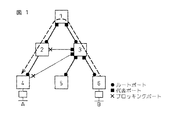
例えば図1において、ブリッジ間でBPDU(Bridge Protocol Data Unit)メッセージを交換することにより、所定の基準に従ってブリッジ1がルートノードに決定される。このとき、ブリッジ1〜6間に図中線分で表わされているセグメントの各々について各セグメントが有するポートの中でルートノードに最も近いポートが図中黒四角で示す代表ポート(designated port)に決定される。また、各ブリッジについて、各ブリッジが有するポートの中でルートノードに最も近いポートが図中黒丸で示すルートポートに決定される。代表ポートでもルートポートでもないポートが図中×印で示すブロッキングポートとなり、図中太線で示すスパニングツリーが形成される。
【0007】
このブロッキングポートを設定することによりループが発生しないというメリットがあるものの、使用されないルートが存在し、(i)トラヒックがルートノードに集中し、ルートノード近辺に輻輳が発生してしまう、(ii)ルートノード経由よりも最適なルートがあっても使用されずネットワークリソースを浪費してしまう、(iii)(i),(ii)により遅延が発生する、という問題がある。
【0008】
これを解決するために、特開平11−355337号公報には、ツリー構造で使用されないルートを使用可能にすることでルートノードを迂回してデータ転送を行うことが記載されている。
【0009】
図2に示すように、上記文献に記載された技術ではスパニング・ツリーにより構成されたネットワークにおいて、ブロッキングポートの存在するノード(例えばブリッジ4)は、接続先のノード(ブリッジ3)に対して、バイパスルートのリクエスト(バイパスリクエスト)10を送信する。バイパスリクエストを受信したノードは、バイパスリクエストに格納されているルーティング情報をもとにルーティングテーブルを書き換える。また、代表ポートに関するルーティング情報をバイパスレスポンス12に格納して返信する。バイパスレスポンスを受信したノードは格納されているルーティング情報をもとにルーティングテーブルを書き換え、バイパスルートを用いて接続先ノードに対してデータ転送を行う。
【0010】
【発明が解決しようとする課題】
前述のバイパスルート構築方法は、以下の理由から現実的ではない。
【0011】
スパニング・ツリーで構成されたネットワークでは、アドレス学習が欠かせない重要機能であり、この機能により宛先を特定するフォワーディングテーブルを作成する。しかし、前述の方式ではアドレス学習について一切言及されておらず、STP情報を元にバイパスルートを構築することとなっており、これによりバイパスルートを構築したとしても、実際にデータを転送する場合に、アドレス学習を考慮していないため、どのバイパスルートに転送してよいか不明であり、本バイパスルートを使用することは現実的に不可能である。また、バイパスリクエストの送出タイミングも不明であり、仮に送出タイミングがブロッキングポートを認識した時点と仮定すると、各ブリッジで交換されるべき情報は作成されていないはずであり、アドレス学習した時点と仮定しても、ネットワーク内の全ノードがアドレス学習する度に頻繁にバイパスリクエストの送出を行うことになり、ノード自体の処理能力およびネットワーク負荷を考慮すると現実ではない。
【0012】
このように、前述の従来技術においては現実的にバイパスルートを使用することは不可能である。
【0013】
また、前述の方式では、そのノードにて相手先ネットワーク(LAN)、メトリック、次ノード情報を持つルーティングテーブルを管理することとしているが、このような情報保持はレイヤ3では可能であるが、レイヤ2では宛先アドレスがどこのネットワーク(LAN)に所属するのかの把握は不可能であり、ノード間でルーティング情報のやり取りも行わない(IEEE802.IDに規定されていない)ことから、このようなルーティングテーブルはレイヤ2では現実的に使用できない。
【0014】
従って、本発明の目的は、アドレス学習をベースにバイパスルートを形成してデータ転送を行うことにより、前述の3つの問題を解決することにある。
【0015】
【課題を解決するための手段】
本発明のスパニングツリーのバイパス方法は、宛先アドレスが第1のアドレスであり送信元アドレスが第2のアドレスである第1のフレームを受信したとき、第1のアドレスを宛先アドレスとするフレームをルートポートに送出することが学習されていれば、第1のフレームをルートポートとともに代表ポートにも送出し、ブロッキングポートから第1のフレームを受信した後において、第2のアドレスを宛先アドレスとする第2のフレームを該ブロッキングポートに送出するステップを具備することを特徴とする。
【0016】
前述のブロッキングポートに送出するステップは、ブロッキングポートから第1のフレームを受信したとき、第2のアドレスを宛先アドレスとするフレームを該ブロッキングポートに送出することを仮学習し、第2のアドレスを宛先アドレスとする第2のフレームを受信したとき、仮学習を正規の学習に切り替えることによって、第2のフレームをブロッキングポートに送出するサブステップを具備することが望ましい。
【0017】
前述の仮学習するサブステップにおいて、第1のアドレスを宛先とするフレームをどのポートに送出するかの学習が済んでいることを条件として、仮学習が行なわれることが望ましい。
【0018】
本発明のスパニングツリーのバイパス装置は、宛先アドレスが第1のアドレスであり送信元アドレスが第2のアドレスである第1のフレームを受信したとき、第1のアドレスを宛先アドレスとするフレームをルートポートに送出することが学習されていれば、第1のフレームをルートポートとともに代表ポートにも送出する手段と、ブロッキングポートから第1のフレームを受信した後において、第2のアドレスを宛先アドレスとする第2のフレームを該ブロッキングポートに送出する手段とを具備することを特徴とする。
【0019】
【発明の実施の形態】
図3は本発明のスパニングツリーのバイパス方法の一実施形態を説明する図である。図3の(a)に示すように、ブリッジ1〜6とそれらの間のセグメントに沿ってブリッジ1をルートノードとするスパニングツリーが形成されており、各ブリッジにおいてアドレス学習が完了しているものとする。
【0020】
端末Bから端末Aを宛先とするフレームが送出されるとブリッジ6を経てブリッジ3に到達する。ブリッジ3では、本発明の方法によれば、端末Aのアドレスを宛先アドレスとするフレームをルートポート(黒丸●)に送出することが学習されているとき、ルートポートへフレームを送出するとともに代表ポート、好ましくはすべての代表ポート(黒四角)へも送出する(代表ポートへのデータ転送機能14)。それ以外の場合、すなわち学習されている送出先が代表ポートであるときは学習されているポートのみに送出される。
【0021】
ブリッジ2およびブリッジ4ではブリッジ3の代表ポートから送出されたフレームがブロッキングポート(×)において受信される。このとき本発明によれば、このフレームの宛先である端末Aのアドレスを宛先アドレスとするフレームをどのポートに送出するかが既に学習済であることを条件として、このフレームの発信元である端末Bのアドレスを宛先アドレスとするフレームを送出するポートとして、このブロッキングポートを仮学習する(ブロッキングポートでの仮学習機能16)。
【0022】
その後、図3(b)に示すように端末Aから端末Bを宛先アドレスとするフレームが送出されると、ブリッジ4では仮学習として記憶されているブロッキングポートを正規の学習に切り替え、すなわち、端末Bのアドレスを宛先とするフレームの送出ポートはこのブロッキングポートであることを学習し、かつそのフレームをブロッキングポートへ送出する(仮学習アドレスによるデータ転送機能18)。
【0023】
これにより、上記のフレームはブリッジ4→ブリッジ3、ブリッジ6のバイパスルートを経て端末Bへ到達する。また、これにより逆方向の端末Bから端末Aへのフレームの転送についてもこのバイパスルートが学習される。
【0024】
前述の仮学習が行なわれる条件として、端末Aのアドレスを宛先アドレスとするフレームの送出ポートが学習済であること、とするのは、そのノードが本来のルートノード経由のルート上にあるノードであることを確認して確実に本来のルートのバイパスルートを設定するためである。また、「仮学習」としたのは端末B宛ての逆方向のフレームが到着するまで正規の学習と区別することにより、ルートノード経由で遅れて到着するフレームのためにバイパスルートの学習が正規の学習で上書きされることを防ぐためである。
【0025】
なお、上記の機能はスパニングツリーを形成するすべてのノードに備わっている必要はなく、図3の例では、少なくともノード3およびノード4のみに上記の機能が備わっていれば、ルートノードをバイパスしたフレームの転送が可能である。
【0026】
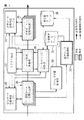
図4はこのバイパス方法を実現する、スパニングツリーのバイパス機能を備えた装置の一実施例としてのブリッジ装置の構成を示す。
【0027】
受信ポート状態判定部20は、データを受信したポートの状態を判定し、状態に応じたデータ転送を行う。状態がブロッキング状態であれば、仮アドレス学習制御部32にもアドレス情報の送信を行う。
【0028】
STP制御部22は、BPDUメッセージの作成・受信、スパニング・ツリーの計算、ポートの状態遷移管理等のスパニング・ツリー・プロトコル制御処理を行う。
【0029】
データ転送制御部24は、フィルタリング制御部28(後述)より入手した方路情報に従って、データ転送制御処理を行う。
【0030】
送信ポート状態判定部26は、ブロッキングポートに正規学習エントリーがあれば、ブロッキングポートを使用して強制的にデータ転送を行う。
【0031】
フィルタリング制御部28は、アドレス学習制御部30(後述)が作成したデータベース34を基に、データ転送時の出方路(出ポート)情報をデータ転送制御部24に通知する。その際、宛先アドレスを学習しているポートがルートポートか否かを判定し、ルートポートの場合は代表ポートにもデータの転送を行うよう通知する。
【0032】
また、宛先アドレスがブロッキングポートにて仮学習されていないか否かを判定し、仮学習されていれば、それを正規学習に切替え、正規学習のデータベースへの登録を行う。
【0033】
アドレス学習制御部30は、ラーニングポート,フォワーディングポートで受信したデータの送信元アドレスとその受信ポートの対応付けを行い、フィルタリング制御に用いるデータベースの作成を行う。
【0034】
仮アドレス学習制御部32は、本発明で新規に設けた機能ブロックであり、ブロッキングポートにて受信したフレームの宛先アドレスを既に他ポートで学習していると判定した場合に、その送信元アドレスと受信ブロッキングポートの対応付けを行い、バイパスルートを作成する基となる仮学習データベース36の作成を行う。
【0035】
本発明では、BPDUメッセージの交換により各ノードのSTP制御部22におけるスパニング・ツリー・プロトコル動作によってスパニング・ツリーが完成したネットワークにおいて、アドレス学習制御部30の機能によりルートポート及び代表ポートでのアドレス学習が従来と変わりなく機能する。このアドレス学習がなされた状態で、フィルタリング制御部28に設けた、学習したポートがルートポートの場合、代表ポートにもデータを転送するようにデータ転送制御部24に通知する機能、即ち、ノード3の代表ポートへのデータ転送機能14(図3)によって、代表ポートへのデータ転送ができるようにしている。ノード3の代表ルートに接続される対向ノード4のポートがブロッキング状態であると、ノード4の受信ポート状態判定部20において、そのアドレス情報を仮アドレス学習制御部32に転送する。仮アドレス学習制御部32では、受信データの宛先アドレス(Aのアドレス)をノード4の他のポートが学習していないかどうかを判定し、既に他のポートで学習している場合には、送信元アドレス(Bのアドレス)の仮学習を行うという機能、即ちブロッキングポートでの仮学習機能16にて仮学習ができるようにしている。この状態(Bのアドレスをノード4のブロッキングポートで仮学習した状態)で、AからB宛てのデータをノード4が受信すると、フィルタリング制御部28に設けた、ブロッキングポートにて仮学習していれば、それを正規学習へ切替え、データ転送制御部24にそのブロッキングポートにデータを転送するように通知する機能と、送信ポート状態判定部26に設けた、ブロッキングポートであっても、正規学習のエントリがあれば強制的にデータを転送する機能、即ち仮学習アドレスによるデータ転送機能18にてブロッキングポートを使ってのデータ転送を可能にしている。これにより、ノード3では従来のブリッジ機能により、Aがノード4対向の代表ルートに存在すると認識できるようになり、そのポート、即ちバイパスルートを使ってのデータ転送が可能となる。
【0036】
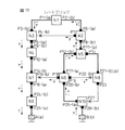
図5は、スパニング・ツリーにより方路が決定される、ブリッジで構成されたネットワークの一例の詳細を示している。図5は、従来のスパニング・ツリー・プロトコル(以下、STPと記述)処理機能、即ちBPDUメッセージの交換により、ブリッジN1をルートブリッジとしたスパニング・ツリーが、太線のように構成されていることを示している。細線はブロッキングされたポートを持つセグメントを示している。N1〜N10は、ネットワークを構成しているブリッジを示している。P1〜P28は、各ブリッジが有するポートを示している。A,Bはフレームを送信する端末、a,bはそれらのMACアドレスを示している。●は各ブリッジにおけるルートポートであり、フォワーディング状態であることを示している。黒四角は各セグメントにおける代表ポートであり、フォワーディング状態であることを示している。×は、そのポートがブロッキング状態であることを示している。
【0037】
本発明は主信号を使ったバイパスルート構築であるため、STPの制御信号であるBPDUメッセージの送受信に関しては何ら影響を与えることはなく、本発明を適用したブリッジであっても、スパニング・ツリーの構築は、従来と同様である。
【0038】
まず、本発明が機能するためにはバイパスルートができる両端のブリッジにてアドレス学習が行われている必要があるため、フレームαとフレームβの転送によって、アドレス学習が従来と変わりなく行われ、本発明で追加した機能が従来の機能に影響を与えていないことをフレーム転送の時系列に沿って説明する。また、この時、図3における代表ポートへのデータ転送機能14、ブロッキングポートでの仮学習機能16、仮学習アドレスによるデータ転送機能18が動作しないことも併せて説明する。
【0039】
図6は、端末Bが初めて端末A宛にフレームαを送信した時に、各ブリッジにおけるフレームαの転送結果を示している。ブリッジN10は、ポートP28よりフレームαを受信し、ポートP26を使って送信元アドレスb、宛先アドレスaのフレームαをブリッジN6向けに転送する。転送処理の詳細は次ブリッジN6を使って説明するので、ここでは割愛する。
【0040】
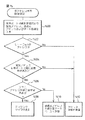
ブリッジN6ではフレームαの転送及びアドレスbの学習が従来と同じく可能であることと、代表ポートへのデータ転送機能14がアドレス学習なしでは機能しないことを説明する。ブリッジN6ではポートP20でフレームαを受信すると、受信ポート状態判定部20において、表1に示す内容の受信ポート状態判定テーブル38を受信ポート番号を検索キーとして参照し、図7のフローに従って受信ポート状態の判定を行う。
【0041】
【表1】
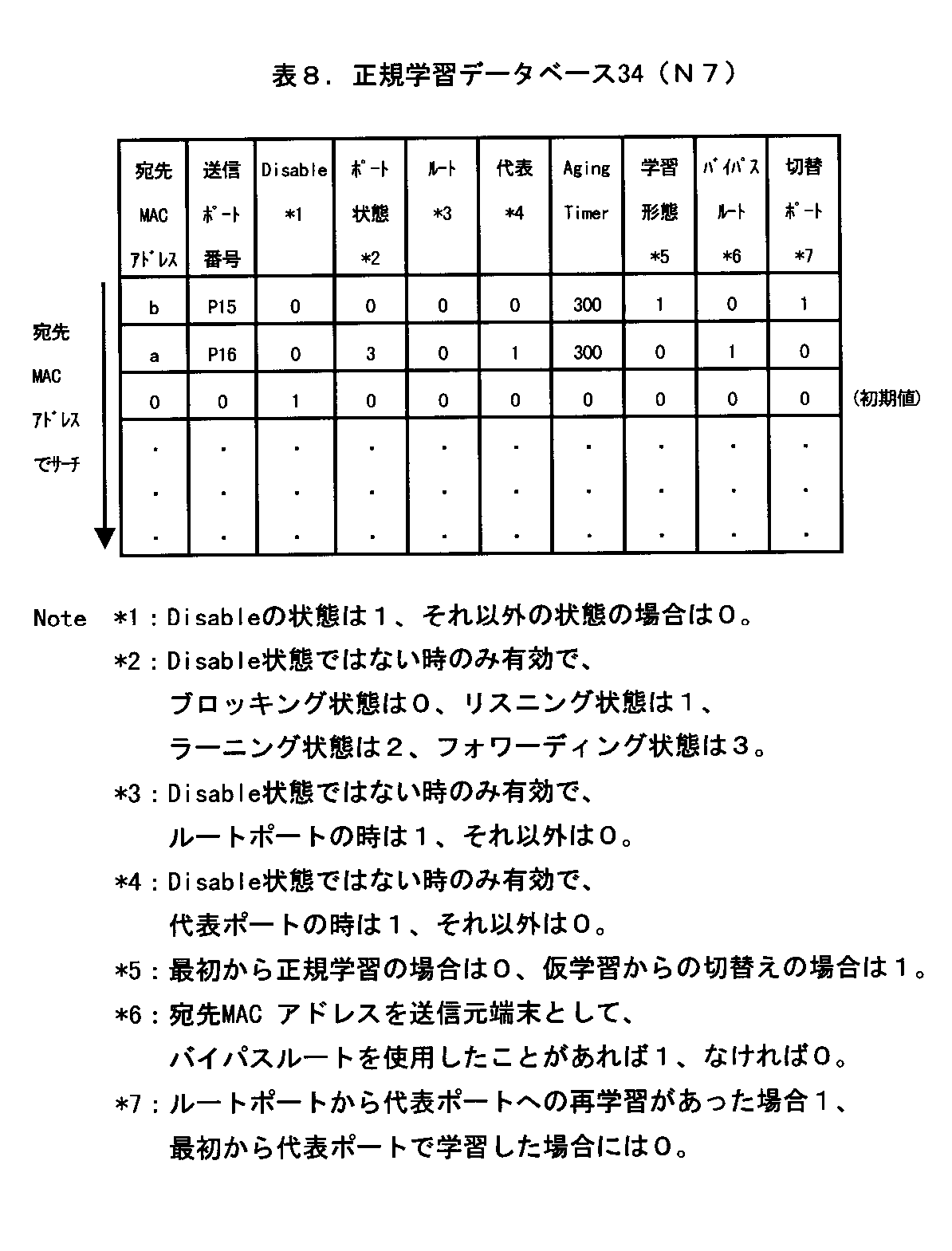
図7の点線に囲まれた処理が、本発明にて追加した処理であるが、表1によればポートP20はフォワーディング状態にあるため、フレームαはステップ1000→1002→1004→1008→1010→1012の順で処理され、データ転送制御部24へ送られる。と同時に、受信ポート状態判定部20より、送信元MACアドレス及びポート情報がアドレス学習制御部30へ送られる(ステップ1010)。これにより、MACアドレスbを持った装置がポートP20の配下に存在することが学習され、表2に示すように正規学習データベース34に登録される。(これで、受信ポート状態判定部20に設けた追加機能が、従来のラーニング機能に影響を与えないことが説明できる。)
【0043】
【表2】
データ転送制御部24では、図8のフローに従う処理を行い、受信ポートがポートP20で宛先アドレスaであるフレームに関する方路(学習)情報の問い合わせをフィルタリング制御部28へ行う(ステップ1104)。フィルタリング制御部28では、図9のフローに従ってまず受信ポート番号を検索キーとして受信ポート状態判定テーブル38を参照し、受信ポートの状態の判定を行う。なお、この処理では、受信ポート状態判定テーブル38を検索しなくても、データ転送制御部24からフレームの先頭にヘッダー情報としてポート状態を付加した形で情報をもらって実行してもよい。この場合で、ポートP20はフォワーディングポートであるので、受信したフレームの宛先MACアドレスを検索キーとして図10および図11のフローに従って表2に示す内容の正規学習データベース34および表3に示す内容を有する仮学習データベース36を参照し、経路情報検索を行う。
【0045】
【表3】
図10の点線に囲まれた処理が、本発明にて追加したフローであるが、表2および表3によれば、アドレスaはどのポートにも学習も仮学習もされていないので、図10,11においてステップ1200→1202→1204→1206→Dの順に処理されて受信ポート以外の全ポートへのブロードキャストを示すポートマップ情報がデータ転送制御部24へ渡される。(これで、フィルタリング制御部28に設けた追加機能が、アドレス学習が行われていない状態において、従来のフィルタリング機能に影響を与えないことがわかる。)
データ転送制御部24は入手したポートマップに従い、フレームαをコピーして、ポートP17、ポートP18、ポートP19の各送信ポート状態判定部26へ転送する(図8ステップ1108)。
【0047】
各ポートに設けられた送信ポート状態判定部26では、送信ポート番号を検索キーとして表4に示す内容の送信ポート状態判定テーブル40を参照し、図14のフローに従う判定を行う。表4によればポートP17、ポートP18及びポートP19はフォワーディング状態にあるため、ステップ1300→ステップ1302と処理されてそれら3つのポート全てがフレームαの送信を行う。
【0048】
【表4】
図6に戻って、ポートP17より送信されたフレームαは、ブリッジN5のポートP12で受信され、ブリッジN6と同様な処理により、ポートP11、ポートP13より送信される。
【0050】
ここで、図3におけるブロッキングポートでの仮学習機能16がアドレス学習なしでは機能しないことを説明する。ポートP18及びポートP19より送信されたフレームαは、ブリッジN7のポートP15及びブリッジN8のポートP22で受信され、図7のフローに従って、それぞれの受信ポート状態判定部20において判定される。この結果、ステップ1000→ステップ1002→ステップ1004→ステップ1006の処理が行なわれ、仮アドレス学習制御部32へアドレス情報が渡されるものの、仮アドレス学習制御部32では、図15に示すフローに従い、宛先アドレスaが他ポートで正規学習されていないため、ステップ1400, 1402, 1404, 1412の処理が行なわれ、仮学習は行われない。また、フレームαはフィルタリング制御部28において、ブロッキングポートでの受信と判定され、図13のステップ1502, 1508の処理により廃棄される。つまり、バイパスルートが構築されていない状態においては、通常のブロッキング機能が働いていることがわかる。
【0051】
以後、同様な処理により、フレームαはブリッジN2→ブリッジN1→ブリッジN3→ブリッジN4→ブリッジN7→ブリッジN9を経由し、端末Aへ送信される。
【0052】
以上の処理により、ブリッジN10のポートP28、ブリッジN6のポートP20、ブリッジN5のポートP12、ブリッジN2のポートP8、ブリッジN1のポートP2、ブリッジN3のポートP3、ブリッジN4のポートP9、ブリッジN7のポートP14、ブリッジN9のポートP24及びブリッジN8のポートP21が端末Bのアドレスbを学習する。フレームαの転送および各ポートでのMACアドレスbの学習結果が、図6に示されている。例えば図中の"P20−(b)"はポートP20で端末BのMACアドレスbを学習していることを示している。
【0053】
次に、図16のように端末Aが初めて端末B宛てにフレームβを送信した(フレームαに対する返信を行った)場合、図3における仮学習アドレスによるデータ転送機能18が作動しないこと、即ち従来のブロッキング機能に影響を与えずにフレームβが転送され、アドレスaが学習されることを説明する。
【0054】
ブリッジN9はポートP25よりフレームβを受信するが、前述の端末Bから端末Aへのフレームαの転送時にポートP24で端末BのMACアドレスbを学習しているので、ポートP24を使って送信元アドレスa、宛先アドレスbのフレームβをブリッジN7向けに送信する。
【0055】
ブリッジN7では、ポートP16でフレームβを受信する。ポートP15はブロッキングポートであるものの、仮学習が行われていないため、アドレスbを学習しているポートP14よりフレームβが転送される。つまり、通常のブロッキング機能が働いている。
【0056】
以後、ブリッジN9,N7と同様な処理により、フレームβはブリッジN4→ブリッジN3→ブリッジN1→ブリッジN2→ブリッジN5→ブリッジN6→ブリッジN10を経由し、端末Bに送信される。
【0057】
以上の処理により、ブリッジN9のポートP25、ブリッジN7のポートP16、ブリッジN4のポートP10、ブリッジN3のポートP5、ブリッジN1のポートP1、ブリッジN2のポートP6、ブリッジN5のポートP11、ブリッジN6のポートP17、ブリッジN10のポートP26が端末Aのアドレスaを学習する。フレームβの転送に伴う各ポートでのMACアドレスaの学習結果が、図16に示されている。
【0058】
以上は、従来のスパニング・ツリーにより方路が決定されるブリッジで構成されたネットワークでのフレーム転送処理結果と同一であり、本発明において追加した機能が何ら影響を与えることなく、双方向のアドレス学習が行われることがわかる。また、アドレス学習がなされていない状態では、バイパスルートが構築されないことがわかる。
【0059】
次に、このように、経路上の各ブリッジが端末A及び端末Bのアドレスを学習した状態において、本発明における追加機能、即ち図3における代表ポートへのデータ転送機能14とブロッキングポートでの仮学習機能16により、ブリッジN6が代表ポートにもデータを転送し、また、ブリッジN7がポートP15について仮学習することを図17を参照して説明する。
【0060】
図17において、端末Bが端末A宛にフレームγを送信した場合、ブリッジN10はポートP28で受信し、アドレス学習に従い、ポートP26よりブリッジN6向けに送信元アドレスb、宛先アドレスaにてフレームγを送信する。転送処理の詳細は次ブリッジN6を使って説明するので、ここでは割愛する。
【0061】
次に、代表ポートへのデータ転送機能14がブリッジN6で機能することを説明する。
【0062】
ブリッジN6ではポートP20でフレームγを受信すると、受信ポート状態判定部20において、受信ポート番号を検索キーとして表1に示す内容の受信ポート状態判定テーブル38を参照し、図7に示すフローに従う判定を行う。表1によればポートP20はフォワーディング状態であるため、フレームγはステップ1000→1002→1004→1008→1010→1012の順に処理され、データ転送制御部24へ送られる。この時、アドレス学習制御部30ではアドレスbの再学習が行われる。
【0063】
データ転送制御部24では、図8のフローに従う判定を行い、受信ポートがポートP20で宛先アドレスaに関する方路(学習)情報の問い合わせをフィルタリング制御部28へ行う(ステップ1104)。フィルタリング制御部28では、フレームα受信時と同様に、まず受信ポート番号を検索キーとして受信ポート状態判定テーブル38を参照し、図9に示す判定を行う。この処理で、ポートP20はフォワーディングポートと分かるので図10のフローに分岐し、受信したフレームの宛先MACアドレスを検索キーとして正規学習データベース34および仮学習データベース36を参照し、経路情報検索を行う。図10および図11において、アドレスaの正規学習がルートポートでなされているため、ステップ1200→1210→1212→1214→Fの処理が行なわれ、学習されているルートポートと代表ポートへの転送を示すポートマップ情報がデータ転送制御部24へ渡される。
【0064】
データ転送制御部24は入手したポートマップに従い、フレームγをコピーして、ポートP17、ポートP18、ポートP19の各送信ポート状態判定部26へ転送する。各送信ポート状態判定部26では、送信ポート番号を検索キーとして送信ポート状態判定テーブル40を参照し、図14の判定を行う。ポートP17、ポートP18及びポートP19はフォワーディング状態にあるため、ステップ1300→1302の処理によりそれら3つのポート全てがフレームγの送信を行う。
【0065】
ポートP17より送信されたフレームγは、ブリッジN5のポートP12で受信され、アドレス学習に従って、ポートP11より送信される。
【0066】
ブロッキングポートでの仮学習機能16がブリッジN7(とブリッジN8)で機能することを説明する。
【0067】
ポートP18及びポートP19より送信されたフレームγは、ブリッジN7のポートP15及びブリッジN8のポートP22で受信され、図7のフローに従って、各受信ポート状態判定部20にて判定される。どちらもブロッキングポートでの受信のため、仮アドレス学習制御部32へアドレス情報、即ち宛先アドレス、送信元アドレスおよび受信ポート情報が渡される(ステップ1006)。(なお、フレームγはフィルタリング制御部28の図12および図13の判定にて廃棄される。つまり、通常のブロッキング機能が働いている。)
仮アドレス学習制御部32では、宛先MACアドレスを検索キーとして、表5に示す内容の正規学習データベース34を参照し、図15の処理フローにて仮学習の要否判定を行う。宛先アドレスaは既にポートP16で学習されているため、ステップ1400→1402→1404→1406→1410の順に処理され、送信元アドレスbがポートP15に仮学習され、仮学習データベース36に表6に示すように登録される。
【0068】
【表5】
【表6】
ブリッジN2ではポートP8よりフレームγを受信すると、ブリッジN6と同様に、ポートP7にもフレームγを送信し、ブリッジN3はブリッジN7と同様に、ポートP4に送信元アドレスbを仮学習する。(ポートP4で受信したフレームγは廃棄される。)
以後、フレームγはブリッジN1→ブリッジN3→ブリッジN4→ブリッジN7→ブリッジN9を経由し、端末Aへ送信される。フレームγの転送およびブロッキングポートでのMACアドレスbの仮学習結果が図17に示されている。
【0071】
次に、このように、ブリッジN7及びN3がアドレスbを仮学習した状態で、本発明における追加機能、即ち図3における仮学習アドレスによるデータ転送機能18にてバイパスルートが構築されることを図18を参照して説明する。
【0072】
図18において、端末Aが端末B宛てにフレームδを送信した場合、ブリッジN9はポートP25にて受信し、アドレス学習に従って、ポートP24よりブリッジN7向けに、送信元アドレスa、宛先アドレスbにてフレームδを送信する。ブリッジN9での転送処理は通常のブリッジ動作と同様なため、ここでは割愛する。
【0073】
仮学習アドレスによるデータ転送機能18がブリッジN7で機能することを説明する。ブリッジN7はポートP16にてフレームδを受信すると、受信ポート状態判定部20にて受信ポート番号を検索キーとして表7に示す内容を有する受信ポート状態判定テーブル38を参照し、図7に示すフローに従って受信ポートの判定を行う。受信したポートがブロッキングポートでないと判定し、データ転送制御部24へフレームδを送る(ステップ1012)。
【0074】
【表7】
データ転送制御部24では、図8のフローに従い、フィルタリング制御部28に宛先アドレスbの経路情報の問い合わせを行う(ステップ1104)。フィルタリング制御部28では、まず受信ポート番号を検索キーとして表7に示す内容を有する受信ポート状態判定テーブル38(N7)を参照し、図9の判定を行う。この処理で、ポートP16はフォワーディングポートと分かるので図10のフローに分岐し、受信したフレームの宛先MACアドレスを検索キーとして表5に示す内容の正規学習データベース34を参照し、図10の経路情報検索を行う。宛先アドレスbがポートP14で学習していると分かるため(ステップ1200)、仮学習をブロッキングポートで仮学習していないかどうかを、宛先アドレスbを検索キーとして表6の仮学習データベース36(N7)を検索する(ステップ1212)。その結果宛先アドレスbをポートP15に仮学習していると判定できるため図11のEに進み、仮学習テーブルの宛先アドレスbに関する学習内容を表8に示すように正規学習テーブルにコピーする。即ち、仮学習を正規学習へ切替え、ブロッキングポートP15への転送を示すポートマップ情報をデータ転送制御部24へ渡す。この時、正規学習データベース34の宛先MACアドレスaにバイパスルートを使っていることを示すバイパスルートビットに"1"を立て、また、ポート情報が変更となった宛先MACアドレスbの切替ポートビットにルートポートより経路が切替わったことを示す"1"も立てる(表8)。さらに、表9に示すように、送信ポート状態判定テーブル40にも正規学習へ切替えた宛先アドレスbのエントリを行う。なお、正規学習切替え後の仮学習データベースは、当該アドレスに関する正規学習が削除される時に削除する。
【0076】
【表8】
【表9】
データ転送制御部24では、このポートマップに従い、ポートP15の送信ポート状態判定部26へフレームδを送信する。従って、それまで使用していたポートP14からはフレームδが送信されることはない。
【0079】
ポートP15の送信ポート状態判定部26では、表9の内容を有する送信ポート状態判定テーブル40を使って、送信ポート番号を検索キーとして図14のフローに示す判定を行い、該ポートがブロッキングポートであるものの、アドレスbの正規学習のエントリがあるため、ポートP15よりフレームδを送信する(ステップ1308)。
【0080】
ブリッジN6では、フレームδをポートP18より受信するため、既存ブリッジ処理にて表10に示すように送信元アドレスaはポートP18の経路に移動したと再学習し、ポートP20よりフレームδを送信する。この時、ポート情報が変更となった宛先MACアドレスaの切替ポートビットにルートポートより経路が切替わったことを示す "1"を立てる。
【0081】
【表10】
ブリッジN10では、ポートP26で受信したフレームδを、アドレス学習に従って、ポートP28より送信する。
【0083】
以後、端末Bより端末A宛てに送信されるフレームは、ブリッジN10→ブリッジN6経由でブリッジN7のポートP15に送信されるようになる。ブリッジN7のポートP15の受信ポート状態判定部20では、受信ポート番号を検索キーとして表7に示す内容の受信ポート状態判定テーブル38(N7)を参照し、図7の処理フローに従って、データ転送制御部24へフレームを送信する。データ転送制御部24では、図8の処理フローに従って処理され、フィルタリング制御部28へ問い合わせを行う。詳細は既に説明しているため割愛。
【0084】
フィルタリング制御部28では、まず受信ポート番号を検索キーとして表7に示す内容の受信ポート状態判定テーブル38(N7)を参照し、図9の処理フローに従って判定を行う。この処理で、表7によればポートP15はブロッキングポートと分かるので図13のフローに分岐し、宛先アドレスを検索キーとして表8の内容の正規学習データベース34を参照して経路情報検索を行う。宛先アドレスaがポートP16で正規学習されているとわかり(ステップ1502)、さらに宛先アドレスaのバイパスルートに"1"が立っていることから、端末Aがこのバイパスルートを使用したことがあると分かり(ステップ1504)、ポートP16への転送を示すポートマップ情報をデータ転送制御部24へ渡す。
【0085】
データ転送制御部24では、このポートマップに従い、ポートP16の送信ポート状態判定部26へフレームを送信する。送信ポート状態判定部26では、ポートP16がブロッキング状態ではないことから、ブリッジN9向けにフレームが送信される。
【0086】
ブリッジN9ではアドレス学習に従って、ポートP25よりフレームを送信する。
【0087】
以後、端末Bより端末A宛てに送信されるデータは、ブリッジN10→ブリッジN6→ブリッジN7→ブリッジN9経由で送信され、端末Aより端末B宛てに送信されるデータは、ブリッジN9→ブリッジN7→ブリッジN6→ブリッジN10経由で送信されるようになる。
【0088】
このようにして、ブリッジN6−ブリッジN7間に端末A−端末B間のバイパスルートが構築される。
【0089】
フレームδの転送およびバイパスルート構築結果が、図18に示されている。なお、不要な学習内容(ブリッジN1,N2,N3,N4,N5,N8でのMACアドレスa,bの学習)は、エイジングタイマのexpireにより削除される。
【0090】
なお、端末A−B間の通信がなく、エイジングタイマがexpireした場合は、ポートP15,P20のアドレスbに関する学習内容およびポートP16,P18のアドレスaに関する学習内容を削除するため、バイパスルートもなくなり、再度通信を行う場合は、本実施例の手順にて再度バイパスルートを構築することになる。
【0091】
最後に、バイパスルート構築後、フレームを送信する端末C〜Fが図19のように増えた場合でも、バイパスルートを使ったフレームの転送が可能であり、従来のブロッキング機能も損なわれていないことを説明する。
【0092】
まず、端末Aと端末Dが通信を行うケースについて説明する。端末Dが端末A宛のフレームX1を送信した場合、ブリッジN6ではアドレスaをポートP18で学習しているため、フレームX1はブリッジN6のポートP18よりブリッジN7のポートP15へとバイパスルートを使って転送される。この場合、ブロッキングポートであるP15でフレームX1を受信することになるが、図13の処理において、宛先アドレスaの正規学習が既にポートP16にあり(ステップ1502)、端末Aは端末Bとの通信のためバイパスルートを既に使用しているため(ステップ1504)、フレームX1はポートP16へと転送され(ステップ1506)通信できる。
【0093】
フレームX1の転送後に端末Aが端末D宛のフレームX2を送信した場合、ポートP15にアドレスdの仮学習がフレームX1の転送によって行われており、端末AはポートP15のバイパスルートを使って転送しているため、図10〜図11のステップ1200→1202→1204→1208→Eの処理により、ブリッジN7→ブリッジN6間のバイパスルートを使ってフレームX2の転送を行う。
【0094】
次にフレームX1が転送されていない状態で端末Aが端末Dよりも先にフレームX3を送信した場合について説明する。端末Dのアドレスdはどのブリッジ/ポートにも学習されていないので、ルートブリッジを経由した転送となる。つまり、従来のブロッキング機能が働いている。この後、ブリッジN6ではポートP17より送信元アドレスa、宛先アドレスdのフレームX3を受信することになり、図10〜図11のステップ1200→1202→1204→1206→Dの処理にてポートP20およびポートP19に転送される。この時、再学習先のポートP18には転送しない。これによりブリッジN10がフレームX3を受信することができ、端末DにフレームX3が転送される。なお、ブリッジN6では、ポートP17でアドレスaを再学習するため、ポートP18におけるアドレスaの学習は消えてしまうことになる。従って、この時点でブリッジN6→ブリッジN7方向のバイパスルートはなくなってしまう。
【0095】
フレームX3の受信完了後、端末Dから端末A宛のフレームX4が送信されると、ブリッジN6では前述のようにポートP18でアドレスaの学習がなくなっているため、ポートP17よりルートブリッジ経由でフレームX4が転送される。以後、端末Aと端末Dの通信ではルートブリッジ経由での通信が行なわれる、つまり、端末Aから端末Dへの通信では一旦バイパスルートが削除されることになるが、前述の端末Aと端末Bの通信と同様な手順にて再度バイパスルートが構築される。
【0096】
次に端末Cと端末Bが通信を行うケースについて説明する。端末Cが端末BにフレームY1を送信した場合、ブリッジN7のポートP15にアドレスbは正規学習されている(端末A−Bの通信で仮学習から正規学習への切替えが既にあった)ので、ブリッジN7−ブリッジN6間のバイパスルートを使って転送される。フレームY1の転送後に端末Bから端末CへフレームY2が送信される場合は、フレームY1の転送によって学習した内容にて転送されるため、ブリッジN7−ブリッジN6間のバイパスルートを使って転送される。
【0097】
次にフレームY1が転送されていない状態で端末Bが端末Cよりも先にフレームY3を送信した場合について説明する。端末Bから端末CへのフレームY3の送信は、ブリッジN6のポートP18にアドレスcが学習されていないので、ポートP17,P18, P19にブロードキャストされるが、ブリッジN7ではアドレスcを学習していないため、ポートP15での仮学習も行われず、フレームY1の転送も行われず、ルートブリッジ経由での転送となる。つまり、従来のブロッキング機能が働いている。この後、ブリッジN7ではポートP14より送信元アドレスb、宛先アドレスcのフレームY3を受信することになり、図10〜図11のステップ1200→1202→1204→1206→Dの処理にてポートP16へ転送する。
【0098】
この時、ブリッジN7では、ポートP14でアドレスbを再学習するため、ブロッキングポートP15におけるアドレスbの学習は消えてしまうことになる。従って、端末Aから端末DへのフレームX3の転送時と同様にバイパスルートは一旦なくなってしまうが、前述の手順にて再構築されることになる。
【0099】
次に、端末Cと端末Dが通信を行う場合について説明する。この場合、端末Aと端末Bの通信によってブリッジN6−ブリッジN7間にバイパスルートが存在するが、端末Cと端末Dのアドレスc,dはどのブリッジにも学習されていないため、前述の端末A−端末B間の通信と同様の処理によりルートブリッジ経由での通信後、端末Cからのフレーム転送をトリガにブリッジN6−ブリッジN7間のバイパスルートを使った通信となる。
【0100】
以上のように、ルートブリッジを起点としてバイパスルートより下位の端末同士が通信を行う場合、従来のブロッキング機能に影響を与えることなく通信が可能であることがわかる。
【0101】
次に、バイパスルートよりルートブリッジに近い端末Eが端末Aと通信する場合について説明する。端末Eが端末AにフレームZ1を送信した場合(ブリッジN1〜5までのアドレスaの学習はエイジングタイマにより消失している場合)、ブリッジN5はアドレスaに関する情報を持っていないためフレームZ1はブロードキャストされ、ルートブリッジを経由するブリッジN5〜ブリッジN1〜ブリッジN9の方路と、バイパスルートのN6→N7を経由する2つの方路ができてしまう。従って、図10〜図11のステップ1200→1202→1204→1206→Cのように、バイパスルートを構築したブリッジN6,N7ではルートポートから代表ポート(またはブロッキングポート)に切替えたアドレスa,b宛てのフレームをルートポートから受信した場合には、その変更したルートへフレームを転送しないようにすれば良い。これは、その切替えたアドレスを表8、表9の「切替ポート」のように、保持しておくことで実現できる。これで、バイパスルート経由のフレーム転送がブロッキングされ、端末Aが両経路からフレームZ1を受信することはなく、ルートポートでの通信が可能となる。つまり、従来のブロッキング機能が働いている。なお、最終的にはブリッジN2−ブリッジN3間のバイパスルートが構築されることになる。
【0102】
端末Aから端末E宛のフレームZ2を送信する場合は、上記フレームZ1の転送後であればブリッジN2−ブリッジN3間のバイパスルートを使った通信となる。フレームZ1の転送前でアドレスeを学習していない場合は、ブリッジN7においてもアドレスeを学習していないためバイパスルートを使った転送が行われることなくブロードキャストされ、通常のブリッジ動作にて、ルートブリッジ経由での通信となる。つまり従来のブロッキング機能が働いている。この場合も最終的には、ブリッジN2−ブリッジN3間のバイパスルートが構築されることになる。
【0103】
端末Fと端末B間の通信も、端末Aと端末E間の通信と同様で、ルートブリッジ経由の通信を行った後、ブリッジN2−ブリッジN3間のバイパスルートを使った通信となる。
【0104】
以上のように、ルートブリッジを起点としてバイパスルートより上位の端末と下位の端末が通信を行う場合、従来のブロッキング機能に影響を与えることなく通信が可能であることがわかる。
【0105】
このように、バイパスルート構築後に他の端末がフレームの送信を行った場合でも、バイパスルートを使ったフレームの転送が可能であり、従来のブロッキング機能にも影響を与えていないことがわかる。
【0106】
(付記1)(a)宛先アドレスが第1のアドレスであり送信元アドレスが第2のアドレスである第1のフレームを受信したとき、第1のアドレスを宛先アドレスとするフレームをルートポートに送出することが学習されていれば、第1のフレームをルートポートとともに代表ポートにも送出し、
(b)ブロッキングポートから第1のフレームを受信した後において、第2のアドレスを宛先アドレスとする第2のフレームを該ブロッキングポートに送出するステップを具備するスパニングツリーのバイパス方法。(1)
(付記2)ステップ(b)は、
(i)ブロッキングポートから第1のフレームを受信したとき、第2のアドレスを宛先アドレスとするフレームを該ブロッキングポートに送出することを仮学習し、
(ii)第2のアドレスを宛先アドレスとする第2のフレームを受信したとき、仮学習を正規の学習に切り替えることによって、第2のフレームをブロッキングポートに送出するサブステップを具備する付記1記載の方法。(2)
(付記3)サブステップ(b)(i)において、第1のアドレスを宛先とするフレームをどのポートに送出するかの学習が済んでいることを条件として、仮学習が行なわれる付記2記載の方法。
【0107】
(付記4)ステップ(a)において、すべての代表ポートへ第1のフレームが送出される付記1記載の方法。
【0108】
(付記5)宛先アドレスが第1のアドレスであり送信元アドレスが第2のアドレスである第1のフレームを受信したとき、第1のアドレスを宛先アドレスとするフレームをルートポートに送出することが学習されていれば、第1のフレームをルートポートとともに代表ポートにも送出する手段と、
ブロッキングポートから第1のフレームを受信した後において、第2のアドレスを宛先アドレスとする第2のフレームを該ブロッキングポートに送出する手段とを具備するスパニングツリーのバイパス装置。(3)
(付記6)前記ブロッキングポート送出手段は、
ブロッキングポートから第1のフレームを受信したとき、第2のアドレスを宛先アドレスとするフレームを該ブロッキングポートに送出することを仮学習する手段と、
第2のアドレスを宛先アドレスとする第2のフレームを受信したとき、仮学習を正規の学習に切り替えることによって、第2のフレームをブロッキングポートに送出する手段とを具備する付記5記載の装置。(4)
(付記7)前記仮学習手段は、第1のアドレスを宛先とするフレームをどのポートに送出するかの学習が済んでいることを条件として、仮学習を行なう付記6記載の装置。(5)
(付記8)前記代表ポート送出手段は、すべての代表ポートへ第1のフレームを送出する付記5記載の装置。
【0109】
【発明の効果】
以上説明したように、本発明によれば、ブロッキングポートでデータを受信した場合の送信元アドレスを仮アドレス学習し、仮アドレス学習後のデータ転送時に仮アドレス学習を正規学習へ切り替えるため、アドレス学習を基本としたバイパスルートの形成が可能となる。また、通常のデータ転送時に、STPのポート状態判定をもとに代表ポートに対してもデータ転送を行うことにより、特別なメッセージを利用することなくバイパスルートを形成することが可能である。これにより、アドレス学習には影響を与えないため、既存ノードとの混在ネットワークの構築が可能である。
【図面の簡単な説明】
【図1】ネットワーク上に形成されたスパニングツリーを示す図である。
【図2】従来技術によるスパニングツリーのバイパス方法を示す図である。
【図3】本発明のスパニングツリーのバイパス方法および装置を説明する図である。
【図4】本発明のスパニングツリーのバイパス方法を実現する装置の一実施例としてのブリッジ装置の構成を示すブロック図である。
【図5】スパニングツリーが形成されたネットワークの一例の詳細を示す図である。
【図6】図5のネットワークにおいて、アドレス学習第1の過程を示す図である。
【図7】受信ポート状態判定部20の処理を示すフローチャートである。
【図8】データ転送制御部24の処理を示すフローチャートである。
【図9】フィルタリング制御部28の処理の第1の部分を示すフローチャートである。
【図10】フィルタリング制御部28の処理の第2の部分を示すフローチャートである。
【図11】フィルタリング制御部28の処理の第3の部分を示すフローチャートである。
【図12】フィルタリング制御部28の処理の第4の部分を示すフローチャートである。
【図13】フィルタリング制御部28の処理の第5の部分を示すフローチャートである。
【図14】送信ポート状態判定部20の処理を示すフローチャートである。
【図15】仮アドレス学習制御部32の処理を示すフローチャートである。
【図16】図5のネットワークにおいて、アドレス学習の第2の過程を示すフローチャートである。
【図17】仮学習までの過程を説明する図である。
【図18】バイパスルートの形成までの過程を説明する図である。
【図19】バイパスルートの形成の後に端末が追加されたときの動作を説明する図である。
【符号の説明】
1〜6,N1〜N10…ブリッジ
P1〜P8…ポート[0001]
BACKGROUND OF THE INVENTION
The present invention relates to a spanning tree bypass method and apparatus configured on a network.
[0002]
In recent years, with the explosive spread of the Internet, there has been a demand for a wide area LAN that can construct a network at a low cost in a network in a provider or a company that provides Internet services to ordinary households.
[0003]
For this reason, in order to effectively use network resources in a wide area LAN, it is necessary to construct a spanning tree that is more efficient than a conventional spanning tree.
[0004]
[Prior art]
In a LAN composed of a plurality of nodes, a network having a tree structure without a loop can be configured using a spanning tree protocol (hereinafter abbreviated as STP). STP is an important protocol defined as an essential function in IEEE 802.1D-1998.
[0005]
A network configured with STP has a loop-free tree structure starting from the root node by setting a blocking port that cannot perform data transfer.
[0006]
For example, in FIG. 1, by exchanging BPDU (Bridge Protocol Data Unit) messages between bridges, the
[0007]
Although there is a merit that loops do not occur by setting this blocking port, there are routes that are not used, (i) traffic is concentrated on the root node, and congestion occurs near the root node. (Ii) Even if there is an optimum route than via the route node, there is a problem that a network resource is wasted without being used, and a delay occurs due to (iii), (i), and (ii).
[0008]
In order to solve this problem, Japanese Patent Application Laid-Open No. 11-355337 describes that data transfer is performed by bypassing the root node by enabling a route that is not used in the tree structure.
[0009]
As shown in FIG. 2, in the technique described in the above document, in a network configured by a spanning tree, a node where a blocking port exists (for example, bridge 4) is connected to a connection destination node (bridge 3). A bypass route request (bypass request) 10 is transmitted. The node that has received the bypass request rewrites the routing table based on the routing information stored in the bypass request. Further, routing information related to the representative port is stored in the bypass response 12 and returned. The node that receives the bypass response rewrites the routing table based on the stored routing information, and transfers data to the connection destination node using the bypass route.
[0010]
[Problems to be solved by the invention]
The bypass route construction method described above is not realistic for the following reasons.
[0011]
In a network composed of spanning trees, address learning is an indispensable important function, and a forwarding table for specifying a destination is created by this function. However, in the above-mentioned method, address learning is not mentioned at all, and a bypass route is constructed based on STP information. Even when the bypass route is constructed by this, when data is actually transferred. Since address learning is not taken into consideration, it is unclear which bypass route can be transferred, and it is practically impossible to use this bypass route. Also, the sending timing of the bypass request is unknown, and assuming that the sending timing is when the blocking port is recognized, the information to be exchanged at each bridge should not have been created, and it is assumed that the address has been learned. However, every time all the nodes in the network learn addresses, a bypass request is frequently sent, which is not realistic considering the processing capability of the nodes themselves and the network load.
[0012]
Thus, in the above-described prior art, it is impossible to use a bypass route practically.
[0013]
In the above-described method, the node manages a routing table having a destination network (LAN), metric, and next node information. Such information holding is possible in
[0014]
Accordingly, an object of the present invention is to solve the above-mentioned three problems by forming a bypass route based on address learning and performing data transfer.
[0015]
[Means for Solving the Problems]
According to the spanning tree bypass method of the present invention, when a first frame whose destination address is the first address and whose source address is the second address is received, the frame having the first address as the destination address is routed. If it is learned to send to the port, the first frame is sent to the representative port together with the root port, and after receiving the first frame from the blocking port, the second address is used as the destination address. Sending two frames to the blocking port.
[0016]
When the first frame is received from the blocking port, the step of sending to the blocking port provisionally learns that a frame having the second address as the destination address is sent to the blocking port, and the second address is It is desirable to include a sub-step of sending the second frame to the blocking port by switching provisional learning to regular learning when the second frame as the destination address is received.
[0017]
In the sub-step for provisional learning described above, it is desirable that provisional learning be performed on the condition that learning has been completed as to which port the frame addressed to the first address is to be transmitted.
[0018]
When the spanning tree bypass device of the present invention receives a first frame whose destination address is the first address and whose source address is the second address, it routes the frame having the first address as the destination address. If it is learned to send to the port, means for sending the first frame to the representative port together with the root port, and after receiving the first frame from the blocking port, the second address as the destination address Means for sending the second frame to the blocking port.
[0019]
DETAILED DESCRIPTION OF THE INVENTION
FIG. 3 is a diagram for explaining an embodiment of the spanning tree bypass method of the present invention. As shown in FIG. 3A, a spanning tree having the
[0020]
When a frame destined for terminal A is transmitted from terminal B, it reaches
[0021]
In the
[0022]
Thereafter, as shown in FIG. 3B, when the frame having the destination address of the terminal B is sent from the terminal A, the blocking port stored in the
[0023]
As a result, the frame reaches the terminal B via the bypass route from the
[0024]
As a condition for the provisional learning described above, it is assumed that the transmission port of the frame whose destination address is the address of the terminal A is already learned because the node is on the route via the original route node. This is for confirming that there is a certain and surely setting the bypass route of the original route. In addition, “temporary learning” is distinguished from regular learning until a reverse frame addressed to terminal B arrives, so that bypass route learning is regular for frames that arrive late via the route node. This is to prevent overwriting by learning.
[0025]
Note that the above function does not need to be provided in all the nodes forming the spanning tree. In the example of FIG. 3, if at least the
[0026]
FIG. 4 shows a configuration of a bridge apparatus as an embodiment of an apparatus having a spanning tree bypass function for realizing the bypass method.
[0027]
The reception port
[0028]
The
[0029]
The data
[0030]
If there is a regular learning entry in the blocking port, the transmission port
[0031]
The
[0032]
Further, it is determined whether or not the destination address has been provisionally learned at the blocking port. If provisional learning has been done, the destination address is switched to regular learning and registered in the regular learning database.
[0033]
The address
[0034]
The temporary address
[0035]
In the present invention, in the network in which the spanning tree is completed by the operation of the spanning tree protocol in the
[0036]
FIG. 5 shows the details of an example of a network composed of bridges whose route is determined by the spanning tree. FIG. 5 shows that a spanning tree having a bridge N1 as a root bridge is configured as a thick line by exchanging a conventional spanning tree protocol (hereinafter referred to as STP) processing function, that is, a BPDU message. Show. A thin line indicates a segment having a blocked port. N1 to N10 indicate bridges constituting the network. P1 to P28 indicate ports that each bridge has. A and B indicate terminals that transmit frames, and a and b indicate their MAC addresses. ● is the root port in each bridge, indicating that it is in the forwarding state. A black square is a representative port in each segment, and indicates a forwarding state. X indicates that the port is in a blocking state.
[0037]
Since the present invention is a bypass route construction using the main signal, it does not affect the transmission / reception of the BPDU message which is the control signal of the STP, and even the bridge to which the present invention is applied can be used for the spanning tree. The construction is the same as before.
[0038]
First, in order for the present invention to function, it is necessary that address learning is performed at the bridges at both ends where a bypass route is possible, so address learning is performed as before by transfer of frame α and frame β, The fact that the function added in the present invention does not affect the conventional function will be described along the time series of frame transfer. In addition, at this time, the fact that the
[0039]
FIG. 6 shows the transfer result of the frame α in each bridge when the terminal B transmits the frame α to the terminal A for the first time. The bridge N10 receives the frame α from the port P28 and transfers the frame α having the source address b and the destination address a to the bridge N6 using the port P26. Details of the transfer process will be described using the next bridge N6, and will not be described here.
[0040]
It will be explained that the bridge N6 can transfer the frame α and learn the address b as before, and that the
[0041]
[Table 1]
The process surrounded by the dotted line in FIG. 7 is the process added in the present invention. According to Table 1, since the port P20 is in the forwarding state, the frame α is in
[0043]
[Table 2]
The data
[0045]
[Table 3]
The process surrounded by the dotted line in FIG. 10 is a flow added in the present invention. According to Tables 2 and 3, since address a is neither learned nor provisionally learned in any port, FIG. , 11, the processing is performed in the order of
The data
[0047]
The transmission port
[0048]
[Table 4]
Returning to FIG. 6, the frame α transmitted from the port P17 is received by the port P12 of the bridge N5, and is transmitted from the port P11 and the port P13 by the same processing as the bridge N6.
[0050]
Here, it will be described that the
[0051]
Thereafter, by the same processing, the frame α is transmitted to the terminal A via the
[0052]
Through the above processing, the port P28 of the bridge N10, the port P20 of the bridge N6, the port P12 of the bridge N5, the port P8 of the bridge N2, the port P2 of the bridge N1, the port P3 of the bridge N3, the port P9 of the bridge N4, and the bridge N7 Port P14, port P24 of bridge N9 and port P21 of bridge N8 learn the address b of terminal B. The transfer result of the frame α and the learning result of the MAC address b at each port are shown in FIG. For example, “P20- (b)” in the figure indicates that the MAC address b of the terminal B is learned at the port P20.
[0053]
Next, as shown in FIG. 16, when terminal A first transmits frame β to terminal B (replies to frame α),
[0054]
The bridge N9 receives the frame β from the port P25, but learns the MAC address b of the terminal B at the port P24 when the frame α is transferred from the terminal B to the terminal A, so that the transmission source using the port P24 is used. The frame β of the address a and the destination address b is transmitted to the bridge N7.
[0055]
The bridge N7 receives the frame β at the port P16. Although port P15 is a blocking port, since provisional learning is not performed, frame β is transferred from port P14 learning address b. That is, the normal blocking function is working.
[0056]
Thereafter, the frame β is transmitted to the terminal B via the bridge N4 → bridge N3 → bridge N1 → bridge N2 → bridge N5 → bridge N6 → bridge N10 by the same processing as the bridges N9 and N7.
[0057]
Through the above processing, port P25 of bridge N9, port P16 of bridge N7, port P10 of bridge N4, port P5 of bridge N3, port P1 of bridge N1, port P6 of bridge N2, port P11 of bridge N5, bridge N6 The port P17 and the port P26 of the bridge N10 learn the address a of the terminal A. FIG. 16 shows the learning result of the MAC address a at each port accompanying the transfer of the frame β.
[0058]
The above is the same as the frame transfer processing result in the network configured by the bridge whose route is determined by the conventional spanning tree, and the bidirectional address is not affected by the function added in the present invention. You can see that learning takes place. In addition, it can be seen that the bypass route is not constructed in a state where address learning is not performed.
[0059]
Next, in the state where each bridge on the route has learned the addresses of the terminals A and B, an additional function in the present invention, that is, the
[0060]
In FIG. 17, when terminal B transmits frame γ to terminal A, bridge N10 receives at port P28, and in accordance with address learning, frame γ is transmitted from port P26 to bridge N6 at source address b and destination address a. Send. Details of the transfer process will be described using the next bridge N6, and will not be described here.
[0061]
Next, it will be described that the
[0062]
In the bridge N6, when the frame γ is received at the port P20, the reception port
[0063]
The data
[0064]
The data
[0065]
The frame γ transmitted from the port P17 is received by the port P12 of the bridge N5, and is transmitted from the port P11 according to address learning.
[0066]
It will be described that the
[0067]
The frame γ transmitted from the port P18 and the port P19 is received by the port P15 of the bridge N7 and the port P22 of the bridge N8, and is determined by each reception port
The temporary address
[0068]
[Table 5]
[Table 6]
When the bridge N2 receives the frame γ from the port P8, it transmits the frame γ to the port P7 as well as the bridge N6, and the bridge N3 provisionally learns the transmission source address b to the port P4, similarly to the bridge N7. (The frame γ received at the port P4 is discarded.)
Thereafter, the frame γ is transmitted to the terminal A via the bridge N1, the bridge N3, the bridge N4, the bridge N7, and the bridge N9. The transfer result of frame γ and the temporary learning result of MAC address b at the blocking port are shown in FIG.
[0071]
Next, in the state where the bridges N7 and N3 have temporarily learned the address b, the bypass route is constructed by the additional function in the present invention, that is, the
[0072]
In FIG. 18, when the terminal A transmits the frame δ addressed to the terminal B, the bridge N9 receives at the port P25, and follows the address learning from the port P24 toward the bridge N7 at the transmission source address a and the destination address b. Send frame δ. Since the transfer process at the bridge N9 is the same as the normal bridge operation, it is omitted here.
[0073]
It will be described that the
[0074]
[Table 7]
The data
[0076]
[Table 8]
[Table 9]
In accordance with this port map, the data
[0079]
The transmission port
[0080]
In the bridge N6, since the frame δ is received from the port P18, as shown in Table 10 in the existing bridge processing, the transmission source address a is relearned that it has moved to the path of the port P18, and the frame δ is transmitted from the port P20. . At this time, “1” indicating that the route has been switched from the root port is set in the switching port bit of the destination MAC address a whose port information has been changed.
[0081]
[Table 10]
In the bridge N10, the frame δ received at the port P26 is transmitted from the port P28 according to address learning.
[0083]
Thereafter, the frame transmitted from the terminal B to the terminal A is transmitted to the port P15 of the bridge N7 via the bridge N10 → the bridge N6. The reception port
[0084]
First, the
[0085]
The data
[0086]
The bridge N9 transmits a frame from the port P25 according to address learning.
[0087]
Thereafter, data transmitted from terminal B to terminal A is transmitted via bridge N10 → bridge N6 → bridge N7 → bridge N9, and data transmitted from terminal A to terminal B is bridge N9 → bridge N7 → It is transmitted via the bridge N6 → the bridge N10.
[0088]
In this way, a bypass route between the terminal A and the terminal B is established between the bridge N6 and the bridge N7.
[0089]
FIG. 18 shows the result of frame δ transfer and bypass route construction. Note that unnecessary learning contents (learning of MAC addresses a and b at bridges N1, N2, N3, N4, N5, and N8) are deleted by expire of the aging timer.
[0090]
When there is no communication between the terminals A and B and the aging timer expires, the learning content related to the address b of the ports P15 and P20 and the learning content related to the address a of the ports P16 and P18 are deleted, so there is no bypass route. When communication is performed again, a bypass route is constructed again according to the procedure of this embodiment.
[0091]
Finally, even if the number of terminals C to F that transmit frames increases as shown in FIG. 19 after constructing the bypass route, frames can be transferred using the bypass route, and the conventional blocking function is not impaired. Will be explained.
[0092]
First, a case where terminal A and terminal D communicate with each other will be described. When the terminal D transmits the frame X1 addressed to the terminal A, since the address a is learned at the port P18 in the bridge N6, the frame X1 uses the bypass route from the port P18 of the bridge N6 to the port P15 of the bridge N7. Transferred. In this case, the frame X1 is received at P15 which is a blocking port, but in the processing of FIG. 13, regular learning of the destination address a already exists at the port P16 (step 1502), and the terminal A communicates with the terminal B. Therefore, since the bypass route is already used (step 1504), the frame X1 is transferred to the port P16 (step 1506) and can be communicated.
[0093]
When terminal A transmits frame X2 addressed to terminal D after transfer of frame X1, provisional learning of address d is performed at port P15 by transfer of frame X1, and terminal A transfers using the bypass route of port P15. Therefore, the frame X2 is transferred using the bypass route between the bridge N7 and the bridge N6 by the processing of
[0094]
Next, the case where the terminal A transmits the frame X3 before the terminal D in a state where the frame X1 is not transferred will be described. Since the address d of the terminal D has not been learned by any bridge / port, the transfer is via the root bridge. That is, the conventional blocking function is working. Thereafter, the bridge N6 receives the frame X3 of the source address a and the destination address d from the port P17, and the port P20 and the port P20 are processed in the
[0095]
After the reception of the frame X3 is completed, when the frame X4 addressed to the terminal A is transmitted from the terminal D, the bridge N6 does not learn the address a at the port P18 as described above, so the frame is transmitted from the port P17 via the root bridge. X4 is transferred. Thereafter, the communication between the terminal A and the terminal D is performed via the root bridge. That is, the communication from the terminal A to the terminal D temporarily deletes the bypass route. The bypass route is constructed again in the same procedure as in the communication.
[0096]
Next, a case where terminal C and terminal B communicate with each other will be described. When the terminal C transmits the frame Y1 to the terminal B, the address b is normally learned at the port P15 of the bridge N7 (the provisional learning has already been switched to the regular learning in the communication of the terminal AB). Transfer is performed using a bypass route between the bridge N7 and the bridge N6. When the frame Y2 is transmitted from the terminal B to the terminal C after the frame Y1 is transferred, the frame Y1 is transferred with the content learned by the transfer of the frame Y1, and therefore is transferred using the bypass route between the bridge N7 and the bridge N6. .
[0097]
Next, a case where terminal B transmits frame Y3 before terminal C in a state where frame Y1 is not transferred will be described. The transmission of the frame Y3 from the terminal B to the terminal C is broadcast to the ports P17, P18, and P19 because the address c is not learned at the port P18 of the bridge N6, but the address c is not learned at the bridge N7. Therefore, provisional learning is not performed at the port P15, the frame Y1 is not transferred, and the transfer is via the root bridge. That is, the conventional blocking function is working. Thereafter, the bridge N7 receives the frame Y3 of the source address b and the destination address c from the port P14, and goes to the port P16 by the processing of
[0098]
At this time, since the bridge N7 relearns the address b at the port P14, the learning of the address b at the blocking port P15 disappears. Therefore, the bypass route once disappears as in the transfer of the frame X3 from the terminal A to the terminal D, but is reconstructed by the above-described procedure.
[0099]
Next, the case where the terminal C and the terminal D communicate will be described. In this case, a bypass route exists between the bridge N6 and the bridge N7 due to the communication between the terminal A and the terminal B, but the addresses c and d of the terminal C and the terminal D are not learned by any bridge. -After the communication via the root bridge by the same processing as the communication between the terminals B, the frame transfer from the terminal C is used as a trigger for the communication using the bypass route between the bridges N6 and N7.
[0100]
As described above, when terminals lower than the bypass route communicate with each other starting from the root bridge, it can be seen that communication is possible without affecting the conventional blocking function.
[0101]
Next, the case where the terminal E closer to the root bridge than the bypass route communicates with the terminal A will be described. When the terminal E transmits the frame Z1 to the terminal A (when the learning of the address a from the bridges N1 to N5 is lost by the aging timer), since the bridge N5 has no information about the address a, the frame Z1 is broadcast. Thus, there are two routes that pass through the bridge N5 via the root bridge and the bridge N1 through the bridge N9 and the bypass route N6 → N7. Therefore, as shown in
[0102]
When the frame Z2 addressed to the terminal E is transmitted from the terminal A, the communication is performed using the bypass route between the bridge N2 and the bridge N3 after the transfer of the frame Z1. If the address e is not learned before the transfer of the frame Z1, the address e is not learned even in the bridge N7, so that the broadcast is performed without the transfer using the bypass route, and the normal bridge operation Communication via a bridge. In other words, the conventional blocking function works. Also in this case, a bypass route between the bridge N2 and the bridge N3 is finally constructed.
[0103]
The communication between the terminal F and the terminal B is the same as the communication between the terminal A and the terminal E, and is communication using the bypass route between the bridge N2 and the bridge N3 after performing communication via the root bridge.
[0104]
As described above, when a terminal higher than the bypass route and a lower terminal communicate with each other starting from the root bridge, it can be seen that communication is possible without affecting the conventional blocking function.
[0105]
Thus, it can be seen that even when another terminal transmits a frame after the bypass route is established, the frame can be transferred using the bypass route, and the conventional blocking function is not affected.
[0106]
(Appendix 1) (a) When receiving a first frame whose destination address is the first address and whose source address is the second address, a frame having the first address as the destination address is transmitted to the root port. If it is learned to do, send the first frame to the representative port along with the root port,
(B) A spanning tree bypass method, comprising: after receiving a first frame from a blocking port, sending a second frame having a second address as a destination address to the blocking port. (1)
(Supplementary Note 2) Step (b)
(I) tentatively learning to send a frame having a second address as a destination address to the blocking port when the first frame is received from the blocking port;
(Ii) A
(Supplementary note 3) In the substeps (b) and (i), provisional learning is performed on the condition that learning is made on which port the frame destined for the first address is sent to. Method.
[0107]
(Supplementary note 4) The method according to
[0108]
(Supplementary Note 5) When a first frame whose destination address is the first address and whose source address is the second address is received, a frame having the first address as the destination address may be sent to the root port. If learned, means for sending the first frame to the representative port along with the root port;
A spanning tree bypass device comprising: means for sending a second frame having a second address as a destination address to the blocking port after receiving the first frame from the blocking port. (3)
(Appendix 6) The blocking port sending means includes:
Means for provisionally learning to send a frame having a second address as a destination address to the blocking port when the first frame is received from the blocking port;
The apparatus according to
(Supplementary note 7) The apparatus according to
(Supplementary note 8) The apparatus according to
[0109]
【The invention's effect】
As described above, according to the present invention, a temporary address learning is performed for a source address when data is received at a blocking port, and the temporary address learning is switched to regular learning at the time of data transfer after temporary address learning. It is possible to form a bypass route based on this. Further, during normal data transfer, a bypass route can be formed without using a special message by transferring data to the representative port based on the STP port status determination. Thereby, since address learning is not affected, it is possible to construct a mixed network with existing nodes.
[Brief description of the drawings]
FIG. 1 is a diagram showing a spanning tree formed on a network.
FIG. 2 is a diagram illustrating a spanning tree bypass method according to the prior art.
FIG. 3 is a diagram illustrating a spanning tree bypass method and apparatus according to the present invention.
FIG. 4 is a block diagram showing a configuration of a bridge device as an embodiment of a device for realizing the spanning tree bypass method of the present invention.
FIG. 5 is a diagram showing details of an example of a network in which a spanning tree is formed.
6 is a diagram illustrating a first process of address learning in the network of FIG. 5;
FIG. 7 is a flowchart showing processing of a reception port
FIG. 8 is a flowchart showing processing of the data
FIG. 9 is a flowchart showing a first part of processing of the
10 is a flowchart showing a second part of the processing of the
FIG. 11 is a flowchart showing a third part of the processing of the
12 is a flowchart showing a fourth part of the processing of the
13 is a flowchart showing a fifth part of the processing of the
14 is a flowchart showing processing of a transmission port
15 is a flowchart showing processing of a temporary address
16 is a flowchart showing a second process of address learning in the network of FIG.
FIG. 17 is a diagram illustrating a process up to provisional learning.
FIG. 18 is a diagram illustrating a process up to formation of a bypass route.
FIG. 19 is a diagram illustrating an operation when a terminal is added after the formation of a bypass route.
[Explanation of symbols]
1-6, N1-N10 ... Bridge
P1-P8 ... Port
Claims (5)
(b)第1のノードからブロッキングポートを経て第1のフレームを受信した第2のノードにおいて、第2のアドレスを宛先アドレスとする第2のフレームを受信したとき、該第2のフレームを該ブロッキングポートに送出するステップを具備するスパニングツリーのバイパス方法。(A) At the first node that has received the first frame whose destination address is the first address and whose source address is the second address, the frame having the first address as the destination address is sent to the root port. If it is learned to do, send the first frame to the representative port along with the root port,
(B) at a second node receiving the first frame after the blocking port from a first node, when the second address receiving a second frame whose destination address, the said second frame A spanning tree bypass method comprising the step of sending to a blocking port.
(i)ブロッキングポートから第1のフレームを受信したとき、第2のアドレスを宛先アドレスとするフレームを該ブロッキングポートに送出することを仮学習し、
(ii)第2のアドレスを宛先アドレスとする第2のフレームを受信したとき、仮学習を正規の学習に切り替えることによって、第2のフレームをブロッキングポートに送出するサブステップを具備する請求項1記載の方法。Step (b)
(I) tentatively learning to send a frame having a second address as a destination address to the blocking port when the first frame is received from the blocking port;
(Ii) comprising a sub-step of sending the second frame to a blocking port by switching provisional learning to regular learning when a second frame having the second address as a destination address is received. The method described.
ブロッキングポートから第2のフレームを受信した後において、第2のフレームの送信元アドレスを宛先アドレスとする第3のフレームを該ブロッキングポートに送出するブロッキングポート送出手段とを具備するスパニングツリーのバイパス装置。It has been learned that when receiving a first frame whose destination address is the first address and whose source address is the second address, a frame having the first address as the destination address is sent to the root port. A means for sending the first frame to the representative port together with the root port;
A spanning tree bypass device comprising blocking port sending means for sending a third frame having a source address of the second frame as a destination address to the blocking port after receiving the second frame from the blocking port .
ブロッキングポートから第2のフレームを受信したとき、第2のフレームの送信元アドレスを宛先アドレスとするフレームを該ブロッキングポートに送出することを仮学習する仮学習手段と、
第2のフレームの送信元アドレスを宛先アドレスとする第3のフレームを受信したとき、仮学習を正規の学習に切り替えることによって、第3のフレームをブロッキングポートに送出する手段とを具備する請求項3記載の装置。The blocking port sending means includes:
Provisional learning means for provisionally learning that when a second frame is received from a blocking port, a frame having a transmission source address of the second frame as a destination address is transmitted to the blocking port;
And a means for sending the third frame to the blocking port by switching provisional learning to regular learning when the third frame having the transmission source address of the second frame as the destination address is received. 3. The apparatus according to 3.
Priority Applications (3)
| Application Number | Priority Date | Filing Date | Title |
|---|---|---|---|
| JP2002013423A JP3963728B2 (en) | 2002-01-22 | 2002-01-22 | Spanning tree bypass method and apparatus |
| US10/198,708 US7072952B2 (en) | 2002-01-22 | 2002-07-18 | Spanning tree bypassing method and apparatus |
| CNB02148757XA CN100431309C (en) | 2002-01-22 | 2002-11-15 | Spanning tree detour method and device |
Applications Claiming Priority (1)
| Application Number | Priority Date | Filing Date | Title |
|---|---|---|---|
| JP2002013423A JP3963728B2 (en) | 2002-01-22 | 2002-01-22 | Spanning tree bypass method and apparatus |
Publications (2)
| Publication Number | Publication Date |
|---|---|
| JP2003218902A JP2003218902A (en) | 2003-07-31 |
| JP3963728B2 true JP3963728B2 (en) | 2007-08-22 |
Family
ID=27650386
Family Applications (1)
| Application Number | Title | Priority Date | Filing Date |
|---|---|---|---|
| JP2002013423A Expired - Fee Related JP3963728B2 (en) | 2002-01-22 | 2002-01-22 | Spanning tree bypass method and apparatus |
Country Status (3)
| Country | Link |
|---|---|
| US (1) | US7072952B2 (en) |
| JP (1) | JP3963728B2 (en) |
| CN (1) | CN100431309C (en) |
Families Citing this family (67)
| Publication number | Priority date | Publication date | Assignee | Title |
|---|---|---|---|---|
| US7056916B2 (en) * | 2002-11-15 | 2006-06-06 | Boehringer Ingelheim Pharma Gmbh & Co. Kg | Medicaments for the treatment of chronic obstructive pulmonary disease |
| US7983239B1 (en) | 2003-01-07 | 2011-07-19 | Raytheon Bbn Technologies Corp. | Systems and methods for constructing a virtual model of a multi-hop, multi-access network |
| US7627654B2 (en) | 2003-06-09 | 2009-12-01 | Foundry Networks, Inc. | System and method for multiple spanning tree protocol domains in a virtual local area network |
| US8307112B2 (en) * | 2003-07-31 | 2012-11-06 | Cloudsoft Corporation Limited | Mediated information flow |
| US7564858B1 (en) | 2003-08-01 | 2009-07-21 | Foundry Networks, Inc. | System and method for enabling a remote instance of a loop avoidance protocol |
| US7558205B1 (en) * | 2003-08-01 | 2009-07-07 | Foundry Networks, Inc. | System and method for detecting and isolating a remote loop |
| US7881229B2 (en) * | 2003-08-08 | 2011-02-01 | Raytheon Bbn Technologies Corp. | Systems and methods for forming an adjacency graph for exchanging network routing data |
| US7606927B2 (en) | 2003-08-27 | 2009-10-20 | Bbn Technologies Corp | Systems and methods for forwarding data units in a communications network |
| US8166204B2 (en) | 2003-08-29 | 2012-04-24 | Raytheon Bbn Technologies Corp. | Systems and methods for automatically placing nodes in an ad hoc network |
| US7668083B1 (en) | 2003-10-28 | 2010-02-23 | Bbn Technologies Corp. | Systems and methods for forwarding data in a communications network |
| JP4398263B2 (en) * | 2004-01-13 | 2010-01-13 | 富士通株式会社 | Route design method |
| US7532623B2 (en) * | 2004-03-24 | 2009-05-12 | Bbn Technologies Corp. | Methods for wireless mesh multicasting |
| CN100372333C (en) * | 2004-06-25 | 2008-02-27 | 杭州华三通信技术有限公司 | Distributed realization of rapid generating tree under multiple CPU environment |
| WO2007066766A1 (en) * | 2005-12-09 | 2007-06-14 | Matsushita Electric Industrial Co., Ltd. | Network system and relay device |
| US20070183416A1 (en) * | 2006-02-07 | 2007-08-09 | Mark Gooch | Per-port penalty queue system for re-prioritization of network traffic sent to a processor |
| US20070230369A1 (en) * | 2006-03-31 | 2007-10-04 | Mcalpine Gary L | Route selection in a network |
| US7453818B2 (en) * | 2006-05-01 | 2008-11-18 | Cisco Technology, Inc. | Detection of potential forwarding loops in bridged networks |
| JP2007318553A (en) * | 2006-05-26 | 2007-12-06 | Fujitsu Ltd | Network managing method |
| EP2030414B1 (en) | 2006-06-12 | 2018-04-04 | Cloudsoft Corporation Limited | Self-managed distributed mediation networks |
| CN101150457B (en) * | 2007-10-25 | 2010-06-16 | 中兴通讯股份有限公司 | Testing method for Ethernet media access control table capacity |
| KR100994127B1 (en) * | 2008-08-28 | 2010-11-15 | 한국전자통신연구원 | Packet processing method for improving Ethernet switch performance |
| US8041378B2 (en) * | 2008-12-19 | 2011-10-18 | Cisco Technology, Inc. | System and method for providing channel configurations in a communications environment |
| US8126494B2 (en) * | 2008-12-19 | 2012-02-28 | Cisco Technology, Inc. | System and method for providing a trunked radio and gateway |
| US20100161727A1 (en) * | 2008-12-19 | 2010-06-24 | Cisco Technology, Inc. | System and Method for Accelerating a Wide Area Notification |
| US8098610B2 (en) | 2009-03-25 | 2012-01-17 | Cisco Technology, Inc. | Multiplexing and demultiplexing radio channels |
| US8139504B2 (en) * | 2009-04-07 | 2012-03-20 | Raytheon Bbn Technologies Corp. | System, device, and method for unifying differently-routed networks using virtual topology representations |
| WO2010123808A1 (en) * | 2009-04-23 | 2010-10-28 | Futurewei Technologies, Inc. | Media access control bridging in a mesh network |
| US9294395B2 (en) | 2009-04-23 | 2016-03-22 | Futurewei Technologies, Inc. | Media access control bridging in a mesh network |
| US8965380B2 (en) * | 2009-08-11 | 2015-02-24 | Cisco Technology, Inc. | System and method for providing access in a network environment |
| US8914520B2 (en) * | 2009-11-16 | 2014-12-16 | Cisco Technology, Inc. | System and method for providing enterprise integration in a network environment |
| US8447314B2 (en) * | 2009-12-21 | 2013-05-21 | Cisco Technology, Inc. | System and method for providing resource management in a network environment |
| US8495142B2 (en) * | 2010-03-11 | 2013-07-23 | Cisco Technology, Inc. | System and method for providing data channel management in a network environment |
| US8400921B2 (en) * | 2010-03-17 | 2013-03-19 | Cisco Technology, Inc. | System and method for providing rate control in a network environment |
| US8553583B2 (en) * | 2011-02-04 | 2013-10-08 | Verizon Patent And Licensing Inc. | Leaky ethernet trees |
| US9007955B1 (en) * | 2011-03-08 | 2015-04-14 | Symantec Corporation | Systems and methods for mapping network topologies |
| US9521074B2 (en) * | 2012-05-10 | 2016-12-13 | Sonos, Inc. | Methods and apparatus for direct routing between nodes of networks |
| US9306841B2 (en) * | 2012-11-05 | 2016-04-05 | Cisco Technology, Inc. | Enabling dynamic routing topologies in support of real-time delay traffic |
| US9130836B2 (en) * | 2013-02-04 | 2015-09-08 | Cisco Technology, Inc. | Provisoning of a new node joining an existing cluster in a data center environment |
| US9286047B1 (en) | 2013-02-13 | 2016-03-15 | Cisco Technology, Inc. | Deployment and upgrade of network devices in a network environment |
| US9413666B2 (en) | 2013-10-02 | 2016-08-09 | Cisco Technology, Inc. | Reporting radio access network congestion information in a network sharing environment |
| CN104243334B (en) * | 2014-09-26 | 2017-08-11 | 新华三技术有限公司 | The method and apparatus for preventing link congestion |
| US9596180B2 (en) * | 2015-01-06 | 2017-03-14 | Cisco Technology, Inc. | Installation of cached downward paths based on upward data traffic in a non-storing low-power and lossy network |
| US10374904B2 (en) | 2015-05-15 | 2019-08-06 | Cisco Technology, Inc. | Diagnostic network visualization |
| US10142353B2 (en) | 2015-06-05 | 2018-11-27 | Cisco Technology, Inc. | System for monitoring and managing datacenters |
| US10536357B2 (en) | 2015-06-05 | 2020-01-14 | Cisco Technology, Inc. | Late data detection in data center |
| US9967158B2 (en) | 2015-06-05 | 2018-05-08 | Cisco Technology, Inc. | Interactive hierarchical network chord diagram for application dependency mapping |
| US10289438B2 (en) | 2016-06-16 | 2019-05-14 | Cisco Technology, Inc. | Techniques for coordination of application components deployed on distributed virtual machines |
| US10708183B2 (en) | 2016-07-21 | 2020-07-07 | Cisco Technology, Inc. | System and method of providing segment routing as a service |
| US10142886B2 (en) | 2016-09-30 | 2018-11-27 | Cisco Technology, Inc. | System and method to facilitate group reporting of user equipment congestion information in a network environment |
| US10972388B2 (en) | 2016-11-22 | 2021-04-06 | Cisco Technology, Inc. | Federated microburst detection |
| US10320652B2 (en) * | 2017-01-09 | 2019-06-11 | Cisco Technology, Inc. | Dynamic installation of bypass path by intercepting node in storing mode tree-based network |
| US10708152B2 (en) | 2017-03-23 | 2020-07-07 | Cisco Technology, Inc. | Predicting application and network performance |
| US10523512B2 (en) | 2017-03-24 | 2019-12-31 | Cisco Technology, Inc. | Network agent for generating platform specific network policies |
| US10250446B2 (en) | 2017-03-27 | 2019-04-02 | Cisco Technology, Inc. | Distributed policy store |
| US10594560B2 (en) | 2017-03-27 | 2020-03-17 | Cisco Technology, Inc. | Intent driven network policy platform |
| US10764141B2 (en) | 2017-03-27 | 2020-09-01 | Cisco Technology, Inc. | Network agent for reporting to a network policy system |
| US10873794B2 (en) | 2017-03-28 | 2020-12-22 | Cisco Technology, Inc. | Flowlet resolution for application performance monitoring and management |
| US10680887B2 (en) | 2017-07-21 | 2020-06-09 | Cisco Technology, Inc. | Remote device status audit and recovery |
| US10554501B2 (en) | 2017-10-23 | 2020-02-04 | Cisco Technology, Inc. | Network migration assistant |
| US10523541B2 (en) | 2017-10-25 | 2019-12-31 | Cisco Technology, Inc. | Federated network and application data analytics platform |
| US10594542B2 (en) | 2017-10-27 | 2020-03-17 | Cisco Technology, Inc. | System and method for network root cause analysis |
| US11233821B2 (en) | 2018-01-04 | 2022-01-25 | Cisco Technology, Inc. | Network intrusion counter-intelligence |
| US10798015B2 (en) | 2018-01-25 | 2020-10-06 | Cisco Technology, Inc. | Discovery of middleboxes using traffic flow stitching |
| US10826803B2 (en) | 2018-01-25 | 2020-11-03 | Cisco Technology, Inc. | Mechanism for facilitating efficient policy updates |
| US10574575B2 (en) | 2018-01-25 | 2020-02-25 | Cisco Technology, Inc. | Network flow stitching using middle box flow stitching |
| US10999149B2 (en) | 2018-01-25 | 2021-05-04 | Cisco Technology, Inc. | Automatic configuration discovery based on traffic flow data |
| US11128700B2 (en) | 2018-01-26 | 2021-09-21 | Cisco Technology, Inc. | Load balancing configuration based on traffic flow telemetry |
Family Cites Families (5)
| Publication number | Priority date | Publication date | Assignee | Title |
|---|---|---|---|---|
| JPH11355337A (en) | 1998-06-12 | 1999-12-24 | Nec Corp | Method and system for constructing bypass route in spanning tree |
| US6304575B1 (en) * | 1998-08-31 | 2001-10-16 | Cisco Technology, Inc. | Token ring spanning tree protocol |
| US6771610B1 (en) * | 1999-01-19 | 2004-08-03 | 3Com Corporation | Spanning tree with protocol for bypassing port state transition timers |
| JP3715501B2 (en) * | 2000-03-10 | 2005-11-09 | アンリツ株式会社 | Spanning tree bridge and route change method using the same |
| JP3664935B2 (en) * | 2000-03-17 | 2005-06-29 | アンリツ株式会社 | Bridge routing method using spanning tree protocol and bridge with spanning tree protocol |
-
2002
- 2002-01-22 JP JP2002013423A patent/JP3963728B2/en not_active Expired - Fee Related
- 2002-07-18 US US10/198,708 patent/US7072952B2/en not_active Expired - Fee Related
- 2002-11-15 CN CNB02148757XA patent/CN100431309C/en not_active Expired - Fee Related
Also Published As
| Publication number | Publication date |
|---|---|
| JP2003218902A (en) | 2003-07-31 |
| US20040255050A1 (en) | 2004-12-16 |
| US7072952B2 (en) | 2006-07-04 |
| CN100431309C (en) | 2008-11-05 |
| CN1434611A (en) | 2003-08-06 |
Similar Documents
| Publication | Publication Date | Title |
|---|---|---|
| JP3963728B2 (en) | Spanning tree bypass method and apparatus | |
| EP0566610B1 (en) | Method and apparatus for transparently bridging traffic across wide area networks | |
| EP0937353B1 (en) | Routing in a multi-layer distributed network element | |
| JP4529144B2 (en) | Virtual LAN system and node device | |
| US6556574B1 (en) | Duplicate ignore delay timer for ARP like protocol messages using are protocol | |
| JP5462360B2 (en) | Method and apparatus at multiple rendezvous points for co-processing multicast traffic from mobile multicast sources | |
| US7778204B2 (en) | Automatic maintenance of a distributed source tree (DST) network | |
| US6873603B1 (en) | MAC address population protocol | |
| KR20030085016A (en) | Method and aparatus for priority-based load balancing for use in an extended local area network | |
| AU1821401A (en) | System for routing and switching in computer networks | |
| EP1005741A1 (en) | Mechanism for packet field replacement in a multi-layer distributed network element | |
| JP2003218901A (en) | Frame relay system, frame relaying apparatus, relaying apparatus, and network | |
| US20030037168A1 (en) | Efficient connectivity between multiple topology subnets via common connection network | |
| JP3449541B2 (en) | Data packet transfer network and data packet transfer method | |
| JPH0888649A (en) | Data communication system | |
| JP3562421B2 (en) | Wireless packet relay route construction method | |
| US20110222541A1 (en) | Network System, Edge Node, and Relay Node | |
| CN110430088B (en) | Method for discovering neighbor nodes and automatically establishing connection in NDN (named data networking) | |
| CN104639417B (en) | A kind of method and apparatus of ADVPN tunnel binding public network link | |
| JPH11355337A (en) | Method and system for constructing bypass route in spanning tree | |
| JP2006165952A (en) | Packet repeater system and packet communication network | |
| JP4751817B2 (en) | Packet transfer apparatus and network system | |
| WO2022242775A1 (en) | Packet processing method and system, and network device | |
| WO2006021988A1 (en) | Relaying apparatus and network | |
| JP2002077234A (en) | Method for setting and control of route in network and active router |
Legal Events
| Date | Code | Title | Description |
|---|---|---|---|
| A621 | Written request for application examination |
Free format text: JAPANESE INTERMEDIATE CODE: A621 Effective date: 20040825 |
|
| A977 | Report on retrieval |
Free format text: JAPANESE INTERMEDIATE CODE: A971007 Effective date: 20060721 |
|
| A131 | Notification of reasons for refusal |
Free format text: JAPANESE INTERMEDIATE CODE: A131 Effective date: 20060815 |
|
| A521 | Request for written amendment filed |
Free format text: JAPANESE INTERMEDIATE CODE: A523 Effective date: 20061011 |
|
| TRDD | Decision of grant or rejection written | ||
| A01 | Written decision to grant a patent or to grant a registration (utility model) |
Free format text: JAPANESE INTERMEDIATE CODE: A01 Effective date: 20070424 |
|
| A61 | First payment of annual fees (during grant procedure) |
Free format text: JAPANESE INTERMEDIATE CODE: A61 Effective date: 20070522 |
|
| R150 | Certificate of patent or registration of utility model |
Free format text: JAPANESE INTERMEDIATE CODE: R150 |
|
| FPAY | Renewal fee payment (event date is renewal date of database) |
Free format text: PAYMENT UNTIL: 20110601 Year of fee payment: 4 |
|
| FPAY | Renewal fee payment (event date is renewal date of database) |
Free format text: PAYMENT UNTIL: 20120601 Year of fee payment: 5 |
|
| FPAY | Renewal fee payment (event date is renewal date of database) |
Free format text: PAYMENT UNTIL: 20120601 Year of fee payment: 5 |
|
| FPAY | Renewal fee payment (event date is renewal date of database) |
Free format text: PAYMENT UNTIL: 20130601 Year of fee payment: 6 |
|
| FPAY | Renewal fee payment (event date is renewal date of database) |
Free format text: PAYMENT UNTIL: 20140601 Year of fee payment: 7 |
|
| LAPS | Cancellation because of no payment of annual fees |