JP3963486B2 - Method and apparatus for capturing mice, mice, etc. - Google Patents
Method and apparatus for capturing mice, mice, etc. Download PDFInfo
- Publication number
- JP3963486B2 JP3963486B2 JP54651198A JP54651198A JP3963486B2 JP 3963486 B2 JP3963486 B2 JP 3963486B2 JP 54651198 A JP54651198 A JP 54651198A JP 54651198 A JP54651198 A JP 54651198A JP 3963486 B2 JP3963486 B2 JP 3963486B2
- Authority
- JP
- Japan
- Prior art keywords
- animal
- trap
- trap door
- chamber
- animals
- Prior art date
- Legal status (The legal status is an assumption and is not a legal conclusion. Google has not performed a legal analysis and makes no representation as to the accuracy of the status listed.)
- Expired - Fee Related
Links
Images


Classifications
-
- A—HUMAN NECESSITIES
- A01—AGRICULTURE; FORESTRY; ANIMAL HUSBANDRY; HUNTING; TRAPPING; FISHING
- A01M—CATCHING, TRAPPING OR SCARING OF ANIMALS; APPARATUS FOR THE DESTRUCTION OF NOXIOUS ANIMALS OR NOXIOUS PLANTS
- A01M23/00—Traps for animals
- A01M23/38—Electric traps
-
- A—HUMAN NECESSITIES
- A01—AGRICULTURE; FORESTRY; ANIMAL HUSBANDRY; HUNTING; TRAPPING; FISHING
- A01M—CATCHING, TRAPPING OR SCARING OF ANIMALS; APPARATUS FOR THE DESTRUCTION OF NOXIOUS ANIMALS OR NOXIOUS PLANTS
- A01M23/00—Traps for animals
- A01M23/02—Collecting-traps
-
- A—HUMAN NECESSITIES
- A01—AGRICULTURE; FORESTRY; ANIMAL HUSBANDRY; HUNTING; TRAPPING; FISHING
- A01M—CATCHING, TRAPPING OR SCARING OF ANIMALS; APPARATUS FOR THE DESTRUCTION OF NOXIOUS ANIMALS OR NOXIOUS PLANTS
- A01M23/00—Traps for animals
- A01M23/02—Collecting-traps
- A01M23/12—Collecting-traps with devices for throwing the animal to a collecting chamber
Abstract
Description
本発明は、特にネズミ、ハツカネズミ及びこれらと類似した動物を個別の室内に捕らえ、ガス、好ましくは二酸化炭素で任意的に殺し、又、動物により検出ユニットを介して解除される作動機構に連結された入口装置を経て上記室内に案内されるような形式の動物捕り器で上記動物を駆除するのに用いられる方法及び器具に関する。
ネズミの駆除は、一般に、毒物を下に置き、或いは罠を仕掛けることにより行われ、毒物を下に置いておくことが、最も広く用いられている方法である。毒性物質を用いることはそれ自体が問題であり、使用に直結した欠点はそれ自体、周知である。これは、例えば子供が何気なく毒物を幾らか食べるという形で人間に危害を加えたり、或いは、家畜及びペット、例えば豚、牛、猫、犬が、下に置かれている毒物を幾らか食べると形でこれらに危害を加える場合がある。ネズミを駆除しても、置かれた毒物の残りがあるのが普通であり、これは環境を損なうほど次第に広がる。しかしながら、最も大きな問題のうちの一つは、ネズミの抵抗力が最新のタイプの毒物にまで直ぐに強くなることであると考えられる。当業者の見解によれば、これは、毒物を下に置いておくことで、これが数年以内に役立たなくなることを意味している。動物に対する倫理的な観点に立てば、既存の毒性物質を用いて動物を内出血で殺すことは、一層非人間的である。これにもかかわらず、ネズミの駆除のために毒物を用いることは依然として最も普及している方法である。
既存の動物又はネズミ捕り器を利用して罠を仕掛けることに関し、これはたとえ専門家でも比較的難しいと考えられ、大抵の場合、上記とは別な理由で毒性物質を使うことが直接禁止されているか、或いは望ましくなく又は不可能な場合に利用されている。これは例えば食品業界、健康部門及び一般に建物内に当てはまる。市場に出ているありふれた動物捕り器、例えば掛け金型動物捕り器及び網型動物捕り器を実際に使ってみた上での経験の示すところによれば、かかる動物捕り器によりネズミが直接又は間接に痛い目にあってこれを仲間に伝え、それにより仲間のネズミが動物捕り器を避けることができることが非常に明らかである。かくして、捕まえられたネズミは、臭いの痕跡を残すことができ、これが他の動物に危険を知らせたり、近づけないようにする。使ってみて分かったことは、最も酷たらしくない機能を備えた動物捕り器が最も有効なものであった。というのは、動物は比較的静かにしているからである。
ネズミ捕り器の幾つかの例を記載している特許文献がある。米国特許第4,741,121号及び米国特許第4,566,218号は、ネズミを二酸化炭素で殺すネズミ捕り器を開示している。しかしながら、これらのネズミ捕り器の構成は比較的複雑であり、その一層本質的な特徴として、ネズミ捕り器がネズミを怯えさせたり不安にさせたりすると共にネズミが臭いの痕跡を残すことにより仲間にネズミ捕り器の存在を教える機会を与えるということがある。
本発明は、最も酷たらしくない機能を備えた動物捕り器が最も有効なものであるという経験則に立脚している。したがって、本発明の目的は、効果的であると共に取扱いの優しい動物の駆除手段を提供することにある。
請求項1に記載された本発明の方法では、動物は、請求項1の前提部分に記載されたタイプの動物捕り器内で入口装置の作動前に、検出ユニットを所定回数、通過するようにし、それにより、動物が動物捕り器に或る程度馴染むようにする。かくして、これら動物のうち何匹かは、捕まるまでに2,3回動物捕り器にやってくる機会をもつ。それにより、かかる何匹かは、群れに戻って動物捕り器で得た良きことを伝えるようになる。さらに、これら動物は、餌仕掛けとは対照的に、実際に餌を取るのが入口装置に関連して行われるので動物捕り器を何とも思わないようになる。動物の経験上の常として、これら動物は望むときに動物捕り器内に行ったり来たりし、餌を食べたりする。一匹が時々居なくなっても、これは仲間には自然なこととして受け取られる。
大抵の場合、例えばネズミやハツカネズミの場合、捕まえた動物を殺すことが行われ、これにはガス、好ましくは二酸化炭素が用いられる。場合によっては、例えば、ミンクのようなイタチを捕まえる際、特にこれらが毛皮動物飼育場から逃げてきた動物であれば、これらを生かしておくことが望ましい場合がある。
本発明の方法の実施に用いられる動物捕り器は、請求項4に記載されており、その特徴は、検出ユニットと作動機構の両方又は何れか一方が、多数の動物が検出ユニットを通過した後に入口装置が解除されるよう構成されていることにある。この関係では、検出ユニットが作動機構の一部を形成できることが注目される。
材料、構成、設計及び食べ物の選択如何により、動物を招き誘う動物捕り器を製作できる。有害小動物が動物捕り器内でそして動物捕り器により痛い目に遭うだけという可能性は、例えば寄せつけないような形、表面、音、匂い等を避けることにより、そして捕殺(捕獲及び殺害)機能を酷たらしくなく、優しく、迅速且つ比較的音をたてないようにすることにより無くなり、従って、動物が捕殺されるとき、或いは一般に動物が動物捕り器内及びその周りに存在しているとき、動物には苦痛や恐怖感は全くない。
さらに、動物捕り器は、それ自体及び有害小動物が長時間にわたって静かなままであるよう構成できる。これは、ガスを自動的に充填すると共に多数の死体を収容可能にすることにより可能となる。また、これにより、動物捕り器を頻繁に点検して空にする必要性が軽減される。
動物捕り器は、空にする作業相互間で捕獲できる有害小動物の最大数が動物捕り器の収容可能数であるようにする調節可能な制限装置を備えるのがよい。最大数制限装置は、電子的又は機械的計数法を利用するものであるのがよく、入りすぎ、その結果として動物捕り器が完全に又は部分的に開き、それにより動物が仲間に痛い目にあったことを伝えるという恐れを招く可能性を無くすものである。
動物捕り器に馴染むようにすることに加えて、捕殺中の動物の迅速且つ酷たらしくない取扱いも又重要である。
本発明によれば、殺害室の入口装置が自動閉鎖式落とし戸として構成されている場合、有害小動物の非常に優しい取扱いが得られる。さらに、落とし戸は、動物が周囲の動物に痛い目にあったことを伝える恐れを無くす。落とし戸は、動物が警告を与える臭い痕跡を床の上に残す恐れなく、動物の下で姿を消す。
本発明は、単純な形態では、落とし戸を上部に取り付けた状態の閉鎖ボックスの形態で実施できる。
落とし戸は、特定の実施形態では、湾曲した横断面を有し、動物が落とし戸の上に立つと落とし戸が回転するように、長手方向軸線の回りに回転自在に吊り下げられている。本実施形態は、動物が這って入り込むことができるトンネルを備えた動物捕り器に用いるのに最適である。落とし戸の回転軸線が落とし戸の重心に対して偏っていて落とし戸が動物の体重だけで回転するようになっている場合、回転を引き起こす機械的補助手段を用いない簡単な構造が得られる。落とし戸が回転すると、動物は、形状的観点から言えば、ほとんど注ぎ込まれるようにして殺害室内へ落ちる。
選択されたガス、例えば二酸化炭素を用いる場合、捕まった動物の倫理的に許容される殺害が可能であり、この殺害は、迅速で無痛の麻痺状態で始まり、これは又、動物が、例えば不安心境を表す臭いを出す前に周囲の動物に痛い目に遭っていることを伝える時間をもつ危険性を無くす。動物を迅速に麻痺させることが決定的に重要なことである。これは、動物を大気よりも重いガス、好ましくは二酸化炭素で殺し、殺害室が少なくとも部分的に、動物の麻痺及び殺害に十分な濃度であるよう前もってガスで充填されるような動物捕り器の構造により実現される。かくして、動物は迅速な殺害を招く毒ガスの雰囲気中へ直に落下し、これはかかる動物がその仲間に痛い目に遭ったことを伝える時間を持たないことを意味する。落とし戸を通過して実際に落下してもそのこと自体では空気が動物からたたき出されることはないが、結局のところ深呼吸を何回もすることになり、これにより麻痺が促進される。さらに、落とし戸が湾曲した形状になっているので、動物は背中又は側部から底に当たりがちであり、これは迅速な殺害に積極的な影響を及ぼす。
原理的には、空気よりも重いガスを用いるので、殺害室を据付け時に充填すれば十分であるが、結局のところ、幾分かのガスは結局は拡散するので、これを補償するのがよい。これができるのは、動物捕り器は、殺害室がガスリザーバからのガスで定期的に自動補充されるよう構成されているからである。
動物捕り器を空にしやすくすると共に動物との接触を避けるために、殺害室は、引出しを備えるのがよく、動物はこの引出しの中へ落下し、この中で殺害される。特に衛生上、引出しを動物が捕集収納される袋で内張りするのがよい。変形例として、殺害室は、袋がこの中に直接吊り下げられるように構成されたものであってもよい。気密プラスチック袋を用いるとガスの拡散が更に減少する。
動物捕り器の構造は、2つのユニットで構成され、即ち、落とし戸及び一般に重要な機械的及び電子的部品を納めた捕獲ユニットを他方のユニットとしての殺害室の頂部に取り付けるようになったものである。別な構造としては、少なくともガス入り壜が殺害室と関連して個別の室内に、好ましくはその側部に配置され、これにより、傾斜安定性を良好にする。というのは、ガス入り壜は一般に動物捕り器に対して比較的重いからである。
動物捕り器の機能は、マイクロプロセッサで適宜制御でき、このマイクロプロセッサにより動物の到来回数に関する情報を収集して処理できる。当然のことながら、同一の動物が検出ユニットを数回通過する場合がある。また、マイクロプロセッサを用いることにより、動物捕り器の解除と関連した到来頻度の調節が容易になり、これは到来頻度に応じて自動調節方式に製作できる。もし到来が非常に頻繁であって多くの動物が存在しているらしいことが分かれば、到来頻度の設定値を増大させるのがよく、逆に、到来頻度が低くて動物がほんの数匹しか存在していないようであれば到来頻度の設定値を減少させるのよい。到来頻度の設定値の調節手段は、当然のことながら純粋に機械的に、例えば機械的計数(カウンター)ユニットを用いて構成できる。
動物捕り器を捕獲したばかりの生きている動物向きに使用できるよう動物捕り器が殺害装置のスイッチを備えるのがよいことは理解されよう。
例えば、食品業界における或る特定の場所では、所定の領域を有害小動物がいるかどうかについて監視することが望ましい。他方、その領域に有害小動物がいなければ動物捕り器をセットすることは望ましくない。これは本発明によれば動物のための入口を備えた器具をその領域中に配置し、これと関連してこの器具内の動物を記録する検出ユニットを設けることにより解決される。この領域内の有害小動物が記録された場合、次にこれらを捕獲するよう動物捕り器をセットするのがよい。
器具それ自体は実質的に、室、落とし戸及び殺害装置の無い動物捕り器に相当する。たとえば、記録装置は、動物捕り器の着脱自在な部分として構成でき、次にこれを別個に使用することができる。有害小動物が観察された場合には、器具を動物捕り器の残部に結合するのが良く、次にこれをセットする。
本発明のネズミ捕り器の一例を添付の図面と関連して以下に一層詳細に説明する。
図1は、入口端から遠近法によって見たズミ捕り器を概略的に示した図である。
図2は、ネズミ捕り器の断面図である。
図3は、ネズミ捕り器の他の実施形態を概略的に示した図である。
図4は、側面から見たネズミ捕り器の実施形態を示す図である。
図5は、図4に示すネズミ捕り器の断面図である。
図6は、図4及び図5に示すネズミ捕り器の解除機構の実施形態を示す図である。
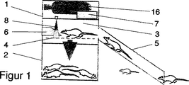
本発明の原理を説明すると、ネズミ捕り器は、2つの部分、即ち、捕獲ユニット1とその下に位置した殺害ユニット2に区分できる。捕獲ユニット1は、その壁により構成された長手方向トンネル状区画室3及び横断面が湾曲している落とし戸ドア4を備えている。トンネルへの入口が、捕獲ユニット1の端に着脱自在に連結された入口管5により得られている。ネズミの餌の入った餌やり器又は餌ディスペンサ6が、トンネルの入口開口部と反対側に設けられている。トンネルの長さは、一度に一匹のネズミしかその中に入ることができないようなものである。同様に、これは側部開口部を備えているので、ネズミは入口管内に巣籠もらないようになっている。床はざらざらしているのに対して、通路は一般に、ネズミが行ったり来たりしやすいように滑らかであると共に、或いはすべすべした形状及び面を有している。
ネズミ捕り器の種々の機能は、電池式の電子制御ユニット7によって制御される。ネズミが居ることを記録する光電センサユニットがトンネルの天井内で餌ディスペンサの直ぐ前に配置されている。このセンサユニットは更に、制御ユニット7と通信し、制御ユニットは、小型空気圧シリンダ、変形例として電子制御式空気弁によって作動される電磁石の形態の作動器8に接続されている。この空気弁は、両端がサスペンションにより捕獲ユニット内に回転自在に吊り下げられた落とし戸4用の保持兼解除ラッチ9を作動させる。作動器は、二酸化炭素入りの壜からの圧縮空気により駆動され、この二酸化炭素入り壜は、ネズミを殺すために用いられ、これについては後で説明する。落とし戸の重さ及び重心に対するそのサスペンション偏り軸線は、落とし戸が解除された時にネズミの体重だけで落とし戸が瞬時に回転してネズミが下に位置した殺害ユニット内へ落下し、或いは「流れ込む」ようにも、また、落とし戸がそれ自体の重さで開始又は始動位置に同様に瞬時に戻るようにも設計されている。回転限度位置におけるネズミ捕り器内の側壁に対する落とし戸の衝撃を弱めるために、衝撃箇所には緩衝器、例えば、ゴム成形品が設けられている。
捕集殺害ユニット2は、落とし戸4により構成された頂部のところに開口部を備えたボックス11と、落下中のネズミのボックス状又は引出し状のインサート12とから成る。インサート12を殺害ユニットの一端から引き抜き、死んだネズミを捕集するためのプラスチック袋13で内張りし、ネズミを捕集して包装状態で取り出すことができるようにするのがよい。かくして、動物に直に触れることはない。
インサートは本実施形態では引抜き式の引出しとして図示されているが、これを傾斜状態の引出しとして構成してもよい。捕獲ユニットと殺害ユニットとの間のこの連結関係によっては、引出しは完全に不必要な場合がある。たとえば、捕獲ユニットを殺害ユニットに回動自在に連結すると、或いは捕獲ユニットが持ち上げて外せるものであれば、実際の殺害ユニットは、捕集袋又は他形態の使い捨てインサートを備えるのがよい。
ネズミを殺すために液体二酸化炭素入りの耐圧壜16からの二酸化炭素が用いられる。ネズミ捕り器の重要な部分を組立て状態に保つために、二酸化炭素入り耐圧壜16を捕獲ユニット内に配置し、耐圧壜16からの管が、減圧制御弁を経て殺害ユニット内へ垂れ下がり、インサート12内の底から上に距離を置いて終端している。二酸化炭素は、大気よりも重いので、インサートの底部上に淀んでこれを約70%満たすようになっており、これは経験上、この中のネズミをほんの数秒で麻痺させ、その後にこれを殺すのに十分であることが分かっている。ネズミが落下すると、二酸化炭素は落とし戸の下の室内全体で攪拌され、これはネズミの迅速な麻痺を促進する。
二酸化炭素のうち幾分かの漸次拡散は、完全には回避できないが、インサートに気密プラスチック袋を設けると、この拡散プロセスは緩慢になる。制御弁を作動させる電子式制御ユニットは、定期的にインサートを補充するようタイマによって設定できる。24時間毎に一回の補充で十分であることが分かった。
図面の図3に示すネズミ捕り器は、基本的に上述のネズミ捕り器と同一構成のものであり、相違点は、落とし戸の構造が本実施形態では、各々の外側部のところでヒンジ止めされた2つの下方に回動自在なフラップ17として構成されていることである。一般に、上記と同一の符号は、同一の部品について用いられている。変形例として、落とし戸を、一方へ引き寄せる形式の引き戸として構成してもよい。
図面の図4及び図5は、個別の室18が殺害ユニット13の片側に設けられている点において上述の2つの実施形態とは異なる本発明のネズミ捕り器のネズミ捕り器の実施形態を示しており、この個別の室18は、ガス入り壜、弁及び電子装置類を収容できる。上方部分1は、図1及び図2に示す例と同一の態様で落とし戸4、餌ディスペンサ及びセンサユニットを有している。上方部分1は、入口の反対側の端部で下方部分2に符号19のところでヒンジ止めされていて前方へ傾斜できるようになっており、下方部分2に係止される閉鎖バックル20が他端に配置されている。ネズミ捕り器の取扱いを容易にするボウル状のキャリヤハンドル21が、側部に設けられた凹部の中に固定されている。「技術的装備室」18の外壁22は、下面が長手方向軸線の回りに符号23のところでヒンジ止めされ、外壁を下方へ回動できるようになっている。閉鎖位置では、外壁は、屋根部分が上方部分1の外壁の後ろを把持する直立フラップを備えているので定位置に保持される。かくして、開放するためには、先ず最初に上方部分1を前方へ回動させて外壁22を外さなければならない。
落とし戸4を安定化させるため、これは入口3の横断面に合った円形切欠き部を有する端部材を備えている。
落とし戸4が開いているのを確実に分かるようにするため、落とし戸は図6に示すように開放機構を備えるのがよい。落とし戸の下面には、解除爪28と協働できるブロック27が取り付けられている。相互係合面は、歯付きであり、或いは摩擦面を備えていて、爪が図示のように落とし戸を確実に始動位置に保持するようになっている。ガス入り壜に連結された空気圧シリンダ29が、爪を解除するのに役立つ。空気圧シリンダを作動することにより、そのピストン30は、その突出したノーズ部分31の下面が爪に作用するようになっている。爪の端は、引張ワイヤ32により落とし戸の下面に連結されていて、爪が解除されると落とし戸が確実に作動して回転できるようになっている。停止部33が、爪の運動を制限するよう配置されている。停止部は、爪が始動位置に自動的にしかも比較的迅速に落ちて戻り、この位置でブロックの係合面に係合する。この点に関し、爪のピボット点は、その重心の上に位置しており、これはちょうど、引張ワイヤの作用点が落とし戸のピボット点の他方の側に位置しているのと同様である。
原理的には、ネズミ又はハツカネズミが或る特定の領域に存在するかどうかを監視する器具は、落とし戸を非作動状態にしたネズミ捕り器の上方部分1により構成できる。或いは、入口室、餌やり器具並びにセンサユニット及び指示器を含む電子ユニットを備えていて、その目的に合った専用装置を製作してもよい。
最初の2つの実施形態では、二酸化炭素入り壜は捕獲ユニット内に配置されているが、変形実施形態として、これを最後の実施形態で示すように殺害ユニット内に配置してもよく、この場合、とりわけ設置位置を下にすれば、ネズミ捕り器は一層安定して立ったままになることができる。
かくして、本発明は、有害小動物の慈悲ある取扱いにより倫理的に許容される動物殺害方式のネズミ捕り器を提供している。The present invention is in particular connected to an operating mechanism where mice, mice and similar animals are captured in separate chambers, optionally killed with gas, preferably carbon dioxide, and also released by the animals via a detection unit. The present invention relates to a method and an instrument used for exterminating the animal with an animal trap of the type guided through the entrance device.
Rats are generally controlled by placing a poison underneath or placing a spear, and placing the poison underneath is the most widely used method. The use of toxic substances is a problem in itself and the drawbacks directly related to its use are well known per se. This can happen if, for example, the child casually eats some poison, or if livestock and pets, such as pigs, cows, cats, dogs, eat some of the poisons underneath. It can harm these in the form. Even when a rat is exterminated, there is usually a venom residue left, which gradually spreads so as to harm the environment. However, one of the biggest problems is thought to be that the resistance of the mouse is quickly increased to the latest type of poison. According to the view of the person skilled in the art, this means that keeping the poison down will make it useless within a few years. From an ethical perspective on animals, killing animals with internal bleeding using existing toxic substances is even more inhuman. Despite this, the use of poisons to control rats remains the most prevalent method.
With regard to setting up traps using existing animals or mousetraps, this can be considered relatively difficult even by experts, and in most cases the use of toxic substances for other reasons is directly prohibited. Or used when it is undesirable or impossible. This is the case for example in the food industry, the health sector and generally in buildings. According to experience with practical use of common animal traps on the market, such as hook-type and net-type animal traps, such animal traps can directly or indirectly cause mice. It is very clear that it can be painful to tell this to the fellow, so that the fellow mouse can avoid the animal trap. Thus, trapped mice can leave a trace of odor, which informs other animals of danger and keeps them away. What I found out after using it was that the animal trap with the least terrible function was the most effective. This is because animals are relatively quiet.
There are patent documents describing some examples of mouse traps. U.S. Pat. No. 4,741,121 and U.S. Pat. No. 4,566,218 disclose a mouse trap that kills mice with carbon dioxide. However, the structure of these mousetraps is relatively complex, and a more essential feature of them is that the mousetraps can make them frightened or anxious, and the mice leave a trace of odors and become friends. Sometimes it gives the opportunity to teach the existence of a mousetrap.
The present invention is based on the rule of thumb that the animal trap with the least severe function is the most effective. Accordingly, it is an object of the present invention to provide a means for controlling animals that is both effective and easy to handle.
In the method of the present invention as set forth in
In most cases, for example in the case of mice or mice, killing the captured animals is carried out, using gas, preferably carbon dioxide. In some cases, for example, when catching weasels such as minks, it may be desirable to keep them alive, especially if they have escaped from the fur animal breeding ground.
The animal trap used for carrying out the method of the present invention is described in
Depending on the choice of materials, composition, design and food, an animal trap that invites and invites animals can be produced. The possibility that a harmful small animal will only hurt in and by an animal trap is, for example, avoiding inaccessible shapes, surfaces, sounds, odors, etc., and a kill function (capture and kill) It is eliminated by not being terrible, gentle, quick and relatively quiet, so when an animal is killed, or generally when an animal is in and around an animal trap There is no pain or fear.
Furthermore, the animal trap can be configured so that itself and the harmful small animal remain silent for a long time. This is made possible by automatically filling the gas and accommodating a large number of corpses. This also reduces the need to frequently check and empty the animal trap.
The animal catcher should include an adjustable restriction device that ensures that the maximum number of harmful small animals that can be captured between emptying operations is the number that can be accommodated by the animal catcher. The maximum number limiting device should use an electronic or mechanical counting method and enter too much, resulting in the animal trap being fully or partially opened, thereby causing the animal to hurt the peers. It eliminates the possibility of incurring the fear of telling what happened.
In addition to being accustomed to animal traps, the rapid and non-harmful handling of animals being killed is also important.
According to the invention, a very gentle handling of harmful small animals is obtained when the entrance device of the killing room is configured as a self-closing trapdoor. In addition, the trapdoor eliminates the fear that the animal has a painful eye to the surrounding animals. The trapdoor disappears under the animal without fear of leaving an odor trail on the floor that gives the animal a warning.
In a simple form, the invention can be implemented in the form of a closed box with a trapdoor attached to the top.
The trapdoor, in certain embodiments, has a curved cross section and is suspended rotatably about a longitudinal axis so that the trapdoor rotates when an animal stands on the trapdoor. This embodiment is most suitable for use in an animal trap equipped with a tunnel through which animals can crawl and enter. If the rotation axis of the trap door is biased with respect to the center of gravity of the trap door and the trap door rotates only with the weight of the animal, a simple structure without using mechanical auxiliary means for causing rotation can be obtained. When the trapdoor rotates, the animal falls almost into the killing room from a geometric point of view.
When using selected gases, such as carbon dioxide, ethically acceptable killing of captured animals is possible, and this killing begins with a rapid and painless paralysis that also causes the animal to Eliminate the risk of having time to tell the surrounding animals that you are in pain before giving out a scent that expresses your feelings. It is crucial to quickly paralyze an animal. This is for animal traps where animals are killed with a heavier gas than the atmosphere, preferably carbon dioxide, and the chamber is at least partially pre-filled with gas so that the concentration is sufficient for paralysis and killing of the animals. Realized by structure. Thus, the animal falls directly into a poisonous gas atmosphere that leads to rapid killing, which means that the animal has no time to tell its peers that it has been painful. Even if it actually falls through the trapdoor, the air itself is not knocked out of the animal, but in the end, it takes many deep breaths, which promotes paralysis. Furthermore, because the trapdoor has a curved shape, animals tend to hit the bottom from the back or sides, which has a positive impact on rapid killing.
In principle, a gas heavier than air is used, so it is sufficient to fill the kill chamber during installation, but after all, some gas will eventually diffuse and should be compensated for this. . This is possible because the animal trap is configured so that the kill chamber is automatically replenished periodically with gas from the gas reservoir.
In order to facilitate emptying the animal trap and avoid contact with the animal, the killing chamber should be equipped with a drawer into which the animal falls and is killed. Particularly for hygiene purposes, the drawer should be lined with a bag in which animals are collected and stored. As a variant, the killing chamber may be configured such that the bag is directly suspended therein. The use of an airtight plastic bag further reduces gas diffusion.
The structure of the animal trap is composed of two units: a trapping door and a trapping unit containing generally important mechanical and electronic components attached to the top of the killing chamber as the other unit. It is. As an alternative, at least the gas-filled soot is placed in a separate chamber, preferably on its side, in relation to the killing chamber, thereby providing good tilt stability. This is because gas traps are generally relatively heavy for animal traps.
The function of the animal trap can be appropriately controlled by a microprocessor, and information regarding the number of arrivals of animals can be collected and processed by this microprocessor. Of course, the same animal may pass through the detection unit several times. In addition, the use of a microprocessor facilitates the adjustment of the arrival frequency associated with the release of the animal trap, which can be manufactured in an automatic adjustment system according to the arrival frequency. If you know that arrivals are very frequent and that there are a lot of animals, you should increase the arrival frequency setting, and conversely there are only a few animals with low arrival frequencies. If not, it is better to decrease the arrival frequency setting. As a matter of course, the means for adjusting the set value of the arrival frequency can be configured purely mechanically, for example, using a mechanical counting (counter) unit.
It will be appreciated that the animal catcher may be equipped with a switch for the killing device so that it can be used for live animals that have just been caught.
For example, in certain locations in the food industry, it is desirable to monitor a given area for small harmful animals. On the other hand, it is not desirable to set an animal trap if there are no harmful small animals in the area. This is solved according to the invention by placing a device with an inlet for the animal in its area and in connection therewith a detection unit for recording the animal in this device. If harmful small animals in this area are recorded, then the animal trap should be set to capture them.
The instrument itself essentially corresponds to an animal trap without chambers, trapdoors and killing devices. For example, the recording device can be configured as a detachable part of an animal trap, which can then be used separately. If a pest is observed, the instrument should be attached to the rest of the animal trap, which is then set.
An example of the mouse trap of the present invention is described in more detail below in connection with the accompanying drawings.
FIG. 1 is a diagram schematically showing a duck catcher as viewed from the entrance end by perspective.
FIG. 2 is a cross-sectional view of the mouse trap.
FIG. 3 is a diagram schematically illustrating another embodiment of the mousetrap.
FIG. 4 is a diagram showing an embodiment of the mouse trap viewed from the side.
FIG. 5 is a cross-sectional view of the mouse trap shown in FIG.
FIG. 6 is a view showing an embodiment of the release mechanism of the mouse trap shown in FIGS. 4 and 5.
Describing the principles of the present invention, the mousetrap can be divided into two parts: a
Various functions of the mouse trap are controlled by a battery-powered
The collecting and
In the present embodiment, the insert is illustrated as a pull-out type drawer, but this may be configured as an inclined drawer. Depending on this connection between the capture unit and the killing unit, the withdrawal may be completely unnecessary. For example, if the capture unit is pivotally connected to the kill unit, or if the capture unit can be lifted and removed, the actual kill unit may include a collection bag or other form of disposable insert.
Carbon dioxide from
Some gradual diffusion of carbon dioxide cannot be completely avoided, but if the insert is provided with an airtight plastic bag, this diffusion process will be slow. The electronic control unit that operates the control valve can be set by a timer to refill the insert periodically. It has been found that one replenishment every 24 hours is sufficient.
The mouse trap shown in FIG. 3 of the drawing has basically the same configuration as that of the mouse trap described above. The difference is that the structure of the trapdoor is hinged at each outer portion in this embodiment. In other words, it is configured as two
FIGS. 4 and 5 of the drawings show an embodiment of the mouse trap of the mouse trap of the present invention which differs from the two embodiments described above in that a
In order to stabilize the
In order to make sure that the
In principle, an instrument for monitoring whether a mouse or mouse is present in a particular area can be constituted by the
In the first two embodiments, the carbon dioxide trap is placed in the capture unit, but as a variant embodiment it may be placed in the killing unit as shown in the last embodiment, in this case Especially if the installation position is down, the mousetrap can remain more stable.
Thus, the present invention provides an animal killing mouse trap that is ethically acceptable by the merciful handling of harmful small animals.
Claims (14)
前記入口装置(4,17)が作動される前に、動物が前記検出ユニット(8)を所定回数、通過することができるようになっており、
前記入口装置(4,17)は、水平なサスペンション偏り軸線に回転自在に取り付けられた自動閉鎖式の落とし戸の形状に構成されており、
前記落とし戸の重心は、前記落とし戸の回転軸線に対して偏っていて、動物が所定回数、前記落とし戸の中に入ることによって、動物の体重により、前記落とし戸が前記水平なサスペンション偏り軸線の回りに回転し、動物が前記落とし戸から出るときに、サスペンション偏り軸線により、前記落とし戸が瞬時に回転して戻るように構成される、
ことを特徴とする方法。In particular, a method associated with trapping mice, mice, and similar animals in an animal trap, and then exterminating them by optionally killing the animal trap, the animal trap are adapted to catch in 13), when the animal is present on the inlet device coupled to the actuating mechanism (7, 9, 10) (4, 17), said actuating mechanism (7, 9, 10) is released through the detection unit (8) by animals in the method are those animals through the inlet device (4, 17) of the form is guided to the chamber (2, 13) in ,
Before the inlet device (4, 17) is activated, the animal can pass through the detection unit (8) a predetermined number of times,
The inlet device (4, 17) is configured in the shape of a self-closing trap door that is rotatably attached to a horizontal suspension bias axis,
The center of gravity of the trap door is biased with respect to the axis of rotation of the trap door, and when the animal enters the trap door a predetermined number of times, the weight of the animal causes the trap door to move toward the horizontal suspension bias axis. The suspension door is configured to rotate and return instantaneously by the suspension bias axis when the animal exits the trap door.
A method characterized by that.
前記検出ユニット(8)及び前記作動機構(7,9,10)のうちの少なくとも一方は、動物が前記検出ユニット(8)を所定回数、通過した後に解除されるように構成されており、
前記入口装置(4,17)は、水平なサスペンション偏り軸線に回転自在に取り付けられた自動閉鎖式の落とし戸の形状に構成され、
前記落とし戸の重心は、前記落とし戸の回転軸線に対して偏っていて、動物が所定回数、前記落とし戸の中に入ることによって、動物の体重により、前記落とし戸が前記水平なサスペンション偏り軸線の回りに回転し、動物が前記落とし戸から出るときに、サスペンション偏り軸線により、前記落とし戸が瞬時に回転して戻るように構成される、
ことを特徴とする器具。Particularly used in connection with extermination of mice, mice, and similar animals, provided with a chamber (2,13) in which an animal is trapped in the chamber (2,13) And an inlet device (4, 17) is provided in the inlet passage for the animal in the animal trap, through which the animal is passed through the chamber (2, 13). In addition, an operating mechanism (7, 9, 10) for operating the inlet device (4, 17 ) is provided, and the inlet device (4, 17) is released. In an instrument provided with a detection unit (8) that is in communication with the actuation mechanism and records the animal in the animal trap,
At least one of the detection unit (8) and the operating mechanism (7, 9, 10) is configured to be released after the animal has passed the detection unit (8) a predetermined number of times,
The inlet device (4, 17) is configured in the shape of a self-closing trap door that is rotatably mounted on a horizontal suspension bias axis.
The center of gravity of the trap door is biased with respect to the axis of rotation of the trap door, and when the animal enters the trap door a predetermined number of times, the weight of the animal causes the trap door to move toward the horizontal suspension bias axis. The suspension door is configured to rotate and return instantaneously by the suspension bias axis when the animal exits the trap door.
A device characterized by that.
Applications Claiming Priority (3)
| Application Number | Priority Date | Filing Date | Title |
|---|---|---|---|
| DK47697 | 1997-04-29 | ||
| DK0476/97 | 1997-04-29 | ||
| PCT/DK1998/000168 WO1998048620A1 (en) | 1997-04-29 | 1998-04-29 | A method and device for trapping rats, mice and the like |
Publications (3)
| Publication Number | Publication Date |
|---|---|
| JP2001523100A JP2001523100A (en) | 2001-11-20 |
| JP2001523100A5 JP2001523100A5 (en) | 2005-12-02 |
| JP3963486B2 true JP3963486B2 (en) | 2007-08-22 |
Family
ID=8093986
Family Applications (1)
| Application Number | Title | Priority Date | Filing Date |
|---|---|---|---|
| JP54651198A Expired - Fee Related JP3963486B2 (en) | 1997-04-29 | 1998-04-29 | Method and apparatus for capturing mice, mice, etc. |
Country Status (10)
| Country | Link |
|---|---|
| US (1) | US6088948A (en) |
| EP (1) | EP1018865B9 (en) |
| JP (1) | JP3963486B2 (en) |
| AT (1) | ATE244503T1 (en) |
| AU (1) | AU7205598A (en) |
| DE (1) | DE69816314T2 (en) |
| DK (1) | DK1018865T3 (en) |
| ES (1) | ES2202842T3 (en) |
| PT (1) | PT1018865E (en) |
| WO (1) | WO1998048620A1 (en) |
Cited By (2)
| Publication number | Priority date | Publication date | Assignee | Title |
|---|---|---|---|---|
| KR100943838B1 (en) * | 2009-10-22 | 2010-02-23 | 주식회사 엠피코씨엠 | Electrical sharing box of underground transmission line having a device for capturing a mouse |
| KR20230013799A (en) * | 2021-07-20 | 2023-01-27 | 국립생태원 | Small animal trap |
Families Citing this family (50)
| Publication number | Priority date | Publication date | Assignee | Title |
|---|---|---|---|---|
| US6344745B1 (en) * | 1998-11-25 | 2002-02-05 | Medrad, Inc. | Tapered birdcage resonator for improved homogeneity in MRI |
| US6718688B2 (en) * | 2000-10-30 | 2004-04-13 | John E. Garretson | Automatic roach trap having disposable container therein |
| US7530195B2 (en) * | 2002-10-02 | 2009-05-12 | Ratco Aps | Electrocution animal trap with a sender |
| US6836999B2 (en) * | 2003-05-05 | 2005-01-04 | Woodstream Corporation | CPU-controlled, rearming, high voltage output circuit for electronic animal trap |
| US6938368B2 (en) * | 2003-10-21 | 2005-09-06 | Gary D. Guidry | Weight adjustable rodent trap |
| US6865843B1 (en) * | 2003-10-23 | 2005-03-15 | Charles Jordan, Sr. | Portable electrical mouse trap |
| US20050235553A1 (en) * | 2004-04-27 | 2005-10-27 | Rail Kenneth D | Rodent elimination system |
| US20060026893A1 (en) * | 2004-08-03 | 2006-02-09 | Sears Richard B | Rodent trap |
| US20060032110A1 (en) * | 2004-08-16 | 2006-02-16 | Keng-Ming Yang | Trapping device |
| CN100350837C (en) * | 2004-11-23 | 2007-11-28 | 徐会林 | Long effective successional method for catching mouse |
| US20060156615A1 (en) * | 2005-01-18 | 2006-07-20 | Brian Hale | Snap trap enclosure for trapping and killing rodents |
| CN101442906A (en) * | 2005-01-23 | 2009-05-27 | 哈梅林有限公司 | Device for managing rodent |
| US20070245617A1 (en) * | 2006-04-21 | 2007-10-25 | Deibert Ronald H | Electronic multiple-use vermin trap and method |
| WO2008035304A2 (en) * | 2006-09-22 | 2008-03-27 | Ecolab Inc. | Versatile pest station with interchangeable inserts |
| DK177937B1 (en) * | 2006-10-19 | 2015-01-19 | Paf Holding Aps | rat trap |
| AU2008220934B2 (en) * | 2007-02-26 | 2013-05-30 | Anticimex Innovation Centre A/S | A rat trap |
| US20080236023A1 (en) * | 2007-03-28 | 2008-10-02 | Ecolab Inc. | Automated pest-trapping device |
| NZ554311A (en) * | 2007-04-02 | 2009-10-30 | Contimo Ltd | A pest control device |
| PL2724616T3 (en) * | 2008-02-06 | 2019-03-29 | Anticimex Innovation Center A/S | A sewer rat trap, a method of installing a rat trap in a sewer, and a sewer shaft with a rat trap |
| CA2621101C (en) * | 2008-03-05 | 2009-10-27 | Animal Deterrent Systems Ltd. | Multiple-use vermin electrocution trap and method |
| BRPI0919265A2 (en) * | 2008-09-22 | 2015-12-15 | Basf Corp | live trap to trap rodents |
| GB0904836D0 (en) * | 2009-03-20 | 2009-05-06 | Biotronics Ltd | Vertebrate trap |
| US7913447B1 (en) * | 2009-03-23 | 2011-03-29 | Jabro Bahjat S | Smart and multiple mouse trap |
| US8695274B2 (en) * | 2009-09-24 | 2014-04-15 | Woodstream Corporation | Single use hermetically sealing mousetrap with internal carbon dioxide killing mechanism |
| US8291637B2 (en) * | 2009-09-25 | 2012-10-23 | B&G Equipment Company | Rodent trap including presence indicator mechanism |
| US9101126B2 (en) * | 2010-01-11 | 2015-08-11 | Jager Pro, Llc | Remote control gate release for trap enclosure |
| WO2012118954A2 (en) * | 2011-03-02 | 2012-09-07 | Woodstream Corporation | Mousetrap with disposable, hermetically sealing cartridge and internal high-voltage killing mechanism |
| AU2013266008A1 (en) * | 2012-05-21 | 2014-12-04 | Pinder, Daryl MR | A self resetting pest trap |
| US20150150236A1 (en) * | 2012-05-29 | 2015-06-04 | Animal Deterrent System Ltd. | Multiple-use vermin trap apparatus, method and system |
| WO2014183014A2 (en) * | 2013-05-09 | 2014-11-13 | Aviantronics, Llc | Species specific extermination device |
| US20150033614A1 (en) * | 2013-07-31 | 2015-02-05 | James Allen Allbright, JR. | Rat Trap Wheel Chock |
| GB2521399B (en) * | 2013-12-18 | 2016-11-16 | Rentokil Initial Plc | Bait station for pest control |
| US20150201628A1 (en) * | 2014-01-21 | 2015-07-23 | Pulse Needlefree Systems, Inc. | System and method to restrain and provide an inhalant agent to an animal |
| WO2016037179A1 (en) | 2014-09-05 | 2016-03-10 | Ap&G Co., Inc. | Rodent trap having improved apparatus to trap rodents |
| WO2016097993A1 (en) | 2014-12-16 | 2016-06-23 | Apice Srl | An electro-mechanical ecological device, for continuous, even multiple, capture of harmful rodents |
| NL2014626B1 (en) * | 2015-04-13 | 2017-01-25 | Bergwerff Frederik | Device and method for removing mice and rats from food. |
| US10015453B2 (en) * | 2015-08-03 | 2018-07-03 | Michael T. Hobbs | Tunnel camera system |
| AU2016348218B2 (en) * | 2015-11-05 | 2021-08-05 | John Michael REDMAYNE | A trap or dispensing device |
| US10512258B2 (en) * | 2016-01-20 | 2019-12-24 | Joseph Baxter | Animal trap with animal entrance encouraging means |
| SE1650107A1 (en) * | 2016-01-29 | 2017-05-02 | Envac Ab | Rodent trapping and removal method and arrangement |
| DK201600097U4 (en) * | 2016-09-01 | 2017-12-22 | Camro Aps | Børne- og kæledyrssikret giftfri gnaverfælde |
| US10842145B2 (en) * | 2017-03-02 | 2020-11-24 | Woodstream Corporation | Self-arming electronic rodent trap and system and method for use thereof |
| CN107372450A (en) * | 2017-08-28 | 2017-11-24 | 徐会林 | Multi-functional continuous mouse catching, hunt device |
| US10085439B1 (en) * | 2018-02-07 | 2018-10-02 | Matthew J. Uhlik | Casino mentality hog trap |
| CN108496947B (en) * | 2018-03-05 | 2021-06-29 | 李先登 | Machine for restraining and trapping multiple mice |
| CN116828981A (en) * | 2020-11-20 | 2023-09-29 | 捕获数据知识产权控股有限公司 | Method and apparatus for controlling pests |
| KR102533700B1 (en) * | 2021-02-03 | 2023-05-17 | 주식회사 녹인 | Amphibious monitoring devices using decoy lamps |
| NL2027856B1 (en) * | 2021-03-29 | 2022-10-12 | Mega Des Plaagdierbeheersing B V | Animal trap and method of operating the animal trap |
| CN113519495A (en) * | 2021-06-27 | 2021-10-22 | 刘修 | Novel mouse trapping device |
| US11730160B1 (en) | 2022-04-29 | 2023-08-22 | Nick Suteerawanit | Electric multi-catch rodent trap |
Family Cites Families (9)
| Publication number | Priority date | Publication date | Assignee | Title |
|---|---|---|---|---|
| US4641456A (en) * | 1985-01-14 | 1987-02-10 | Robert Boharski | Mouse trap |
| US4741121A (en) * | 1986-03-13 | 1988-05-03 | Andrew J. Pratscher | Gas chamber animal trap |
| CH670709A5 (en) * | 1986-04-24 | 1989-06-30 | Univ Moskovsk | |
| CH672709A5 (en) * | 1987-06-12 | 1989-12-29 | Paul Degen Kunz | Mouse trap with capacitive sensor - uses sensor to control release electromagnet for hinged plate above smooth-side container |
| US4890415A (en) * | 1988-12-19 | 1990-01-02 | Fressola Alfred A | Timing device for live animal traps |
| NL8901035A (en) * | 1989-04-25 | 1990-11-16 | Ecotronics Bv | SYSTEM FOR THE REGISTRATION AND / OR CONTROL OF RODENTS SUCH AS MICE AND RATS. |
| US5265371A (en) * | 1992-06-22 | 1993-11-30 | Mccuistion Iii Alvin J | Box shaped rat trap |
| DE19537851C2 (en) * | 1995-10-11 | 1997-07-17 | Franz J Gschwind | Device for catching and killing small rodents, especially rats |
| US5815982A (en) * | 1996-11-14 | 1998-10-06 | Garretson; John E. | Automatic insect trap using infrared beam of radiation |
-
1998
- 1998-04-29 EP EP98919083A patent/EP1018865B9/en not_active Expired - Lifetime
- 1998-04-29 AT AT98919083T patent/ATE244503T1/en not_active IP Right Cessation
- 1998-04-29 WO PCT/DK1998/000168 patent/WO1998048620A1/en active IP Right Grant
- 1998-04-29 PT PT98919083T patent/PT1018865E/en unknown
- 1998-04-29 AU AU72055/98A patent/AU7205598A/en not_active Abandoned
- 1998-04-29 DK DK98919083T patent/DK1018865T3/en active
- 1998-04-29 JP JP54651198A patent/JP3963486B2/en not_active Expired - Fee Related
- 1998-04-29 ES ES98919083T patent/ES2202842T3/en not_active Expired - Lifetime
- 1998-04-29 DE DE69816314T patent/DE69816314T2/en not_active Expired - Fee Related
-
1999
- 1999-10-28 US US09/428,653 patent/US6088948A/en not_active Expired - Fee Related
Cited By (3)
| Publication number | Priority date | Publication date | Assignee | Title |
|---|---|---|---|---|
| KR100943838B1 (en) * | 2009-10-22 | 2010-02-23 | 주식회사 엠피코씨엠 | Electrical sharing box of underground transmission line having a device for capturing a mouse |
| KR20230013799A (en) * | 2021-07-20 | 2023-01-27 | 국립생태원 | Small animal trap |
| KR102605648B1 (en) | 2021-07-20 | 2023-11-22 | 국립생태원 | Manchurian weasel trap |
Also Published As
| Publication number | Publication date |
|---|---|
| AU7205598A (en) | 1998-11-24 |
| WO1998048620A1 (en) | 1998-11-05 |
| US6088948A (en) | 2000-07-18 |
| ES2202842T3 (en) | 2004-04-01 |
| EP1018865B1 (en) | 2003-07-09 |
| DE69816314D1 (en) | 2003-08-14 |
| EP1018865A1 (en) | 2000-07-19 |
| DK1018865T3 (en) | 2003-10-13 |
| PT1018865E (en) | 2003-11-28 |
| EP1018865B9 (en) | 2004-08-11 |
| ATE244503T1 (en) | 2003-07-15 |
| DE69816314T2 (en) | 2004-05-13 |
| JP2001523100A (en) | 2001-11-20 |
Similar Documents
| Publication | Publication Date | Title |
|---|---|---|
| JP3963486B2 (en) | Method and apparatus for capturing mice, mice, etc. | |
| US20220330539A1 (en) | Rodent traps | |
| US7540109B2 (en) | Humane trap for small animals | |
| US8104222B2 (en) | Animal trap | |
| US7171777B2 (en) | Disposable trap | |
| US3992803A (en) | Mouse trap | |
| CA1093301A (en) | Self-locking disposable rodent trap | |
| US20170265451A1 (en) | Self Resetting Pest Trap | |
| JP2010523110A (en) | Pest control device | |
| JPS61132131A (en) | Rat trap device | |
| AU2012366780A1 (en) | Improved animal trap | |
| WO2017188828A1 (en) | Improvements to traps and / or bait dispensing apparatus | |
| US20170112119A1 (en) | Baited Animal Trap | |
| WO1988000008A1 (en) | Animal trap | |
| US20050279015A1 (en) | Awesome rat & mouse trap | |
| US20200288696A1 (en) | Rodent Trap | |
| US5809688A (en) | Reuseable rodent trap | |
| CA1260268A (en) | Rodent trap | |
| US5329724A (en) | Rodent trap | |
| KR200478938Y1 (en) | Pest catcher | |
| US4379374A (en) | Rodent trap | |
| US5050336A (en) | Disposable animal trap | |
| US3996690A (en) | Combination insect trap and swatter device | |
| NL2023078B1 (en) | Device and container for keeping poultry | |
| CA1315552C (en) | Disposable animal trap |
Legal Events
| Date | Code | Title | Description |
|---|---|---|---|
| A521 | Request for written amendment filed |
Free format text: JAPANESE INTERMEDIATE CODE: A523 Effective date: 20050427 |
|
| A621 | Written request for application examination |
Free format text: JAPANESE INTERMEDIATE CODE: A621 Effective date: 20050427 |
|
| A131 | Notification of reasons for refusal |
Free format text: JAPANESE INTERMEDIATE CODE: A131 Effective date: 20060926 |
|
| A601 | Written request for extension of time |
Free format text: JAPANESE INTERMEDIATE CODE: A601 Effective date: 20061222 |
|
| A602 | Written permission of extension of time |
Free format text: JAPANESE INTERMEDIATE CODE: A602 Effective date: 20070219 |
|
| A521 | Request for written amendment filed |
Free format text: JAPANESE INTERMEDIATE CODE: A523 Effective date: 20070226 |
|
| TRDD | Decision of grant or rejection written | ||
| A01 | Written decision to grant a patent or to grant a registration (utility model) |
Free format text: JAPANESE INTERMEDIATE CODE: A01 Effective date: 20070424 |
|
| A61 | First payment of annual fees (during grant procedure) |
Free format text: JAPANESE INTERMEDIATE CODE: A61 Effective date: 20070522 |
|
| R150 | Certificate of patent or registration of utility model |
Free format text: JAPANESE INTERMEDIATE CODE: R150 |
|
| LAPS | Cancellation because of no payment of annual fees |