JP3963243B2 - Beer container dispenser - Google Patents
Beer container dispenser Download PDFInfo
- Publication number
- JP3963243B2 JP3963243B2 JP24691499A JP24691499A JP3963243B2 JP 3963243 B2 JP3963243 B2 JP 3963243B2 JP 24691499 A JP24691499 A JP 24691499A JP 24691499 A JP24691499 A JP 24691499A JP 3963243 B2 JP3963243 B2 JP 3963243B2
- Authority
- JP
- Japan
- Prior art keywords
- beer
- pouring
- motor
- container
- beer container
- Prior art date
- Legal status (The legal status is an assumption and is not a legal conclusion. Google has not performed a legal analysis and makes no representation as to the accuracy of the status listed.)
- Expired - Fee Related
Links
Images
Landscapes
- Details Of Rigid Or Semi-Rigid Containers (AREA)
- Devices For Dispensing Beverages (AREA)
Description
【0001】
【発明の属する技術分野】
この発明は、ビール容器用注出器に関するもので、更に詳細には、泡立ち機能を具備するビール容器用注出器に関するものである。
【0002】
【従来の技術】
一般に、ビールの泡は、ビールから炭酸ガスが逃げるのを防ぐと共に、ビールが空気に触れて酸化するのを防ぐ働きを有する。したがって、きめの細かいクリーミイーな泡立ちのビールが旨味を増すといわれている。
【0003】
そこで、例えば2リットルや3リットル入りのビール缶等のビール容器内のビールをグラスやジョッキ等の容器に注ぐ際に、泡立ちを良くするために注出口に種々の工夫がされている。泡立ちを良くする手段の一つとして、注出口の流出路内にビールの流通によって回転する回転体を配設したものが知られている(実公平3−50031号公報、実公平3−38128号公報参照)。この構造のものは、注出口の流出路内を流れるビールによって回転体が回転することによって、乱流を生じさせてビールを撹拌することで泡立ちを良くするものである。
【0004】
【発明が解決しようとする課題】
しかしながら、上記実公平3−50031号公報、実公平3−38128号公報に記載のものは、注出口の流出路を流れるビールの流量や流速によって回転体の回転が左右されるため、安定した泡立ちが得られないという問題がある。また、回転体には、ビールの流出方向の力と回転体の回転方向の半分の力が相反するので、回転体が円滑に回転できず、泡立ち機能が十分でないという問題もある。
【0005】
この発明は、上記事情に鑑みなされたもので、ビール容器内のビールを注ぐ際に、強制的に乱流を生じせしめて泡立ちを良好にするビール容器用注出器を提供することを目的とするものである。
【0006】
【課題を解決するための手段】
上記目的を達成するために、請求項1記載の発明は、ビール容器の口部に装着される取付部と、この取付部から外方に延在する注出部とを有すると共に、ビール容器内と連通する流出路を有する注出体と、 上記注出体の流出路内に配設される回転体と、 上記回転体を回転駆動するモータと、 上記注出体の注出部に一端が連結され、他端がビール容器の肩部に係止可能な保持部と、を具備し、 上記保持部に、モータの駆動用電池を着脱可能に収容すると共に、モータと電池を接続するリード線を配設し、かつ、保持部のビール容器の肩部側にスイッチを配設してなることを特徴とする。
【0007】
このように構成することにより、ビール容器内のビールを注ぐ際に、モータを駆動させて回転体を強制的に回転させるため、この回転体の回転によってビールに撹拌エネルギが付与される。そのため、ビール流体には乱流が発生し、流出路内にある回転体近傍のビール流体微少空間内で大きな圧力差が時間的に激しく変動し、過飽和に存在するビール流体内の炭酸ガスがその自由エネルギを下げるために、極めて短時間に気体へ相分離する。したがって、安定したきめの細かい泡を立てることができる。このことは、ビールを注ぐ際に発生するビール流体の位置エネルギ変化の一部を、ビール流体が回転体や障害物によって乱流に変換されるという従来の機構とは乱流の大きさにおいて全く異なるものである。
【0008】
請求項2記載の発明は、ビール容器の口部に装着される取付部と、この取付部から外方に延在する注出部とを有すると共に、ビール容器内と連通する流出路を有する注出体と、 上記注出体の流出路内に配設され、流出路内を流れるビールの流れ方向に対して垂直方向に回転軸を有する回転体と、 上記回転体を回転駆動するモータと、 上記注出体の注出部に一端が連結され、他端がビール容器の肩部に係止可能な保持部と、を具備し、 上記保持部に、モータの駆動用電池を着脱可能に収容すると共に、モータと電池を接続するリード線を配設し、かつ、保持部のビール容器の肩部側にスイッチを配設してなることを特徴とする。
【0009】
このように構成することにより、ビールの流れ方向に対して垂直方向に回転軸を有する回転体をモータにて強制的に回転させるため、上記請求項1記載の発明に加えて更に乱流を発生し易くすることができ、より一層安定したきめの細かい泡を立てることができる。
【0011】
また、請求項1,2記載の発明によれば、注出体の注出部に一端が連結される保持部に電池を収容すると共に、保持部の他端をビール容器の肩部に係止させて取り付けることができるので、注出器を安定した状態でビール容器に取り付けることができる。また、保持部のビール容器の肩部側にスイッチを配設することにより、ビール容器に取り付けられた取手を持ってビールを注ぐ際、取手を掴んだ手の親指又は人差し指でスイッチを操作することができる。したがって、ビールを注ぐ際のスイッチ操作を簡単にすることができると共に、泡の量や泡立ちのタイミング等の調整を自由に行うことができる。
【0012】
【発明の実施の形態】
以下に、この発明のビール容器用注出器の実施形態について、添付図面に基づいて詳細に説明する。
【0013】
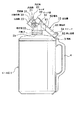
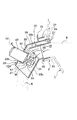
図1は、この発明のビール容器用注出器の一例の使用状態を示す一部断面側面図、図2は、注出器の要部を示す断面図である。
【0014】
上記注出器10は、ビール容器例えば2〜3リットル入りのアルミニウム製のビール缶1の口部2に着脱可能に装着される注出体20と、この注出体20に設けられた流出路21内に配設される回転体30と、この回転体30を回転駆動するモータ40と、モータ駆動用電池50を収容すると共に、モータ40と電池50とを接続するリード線52を配設する保持部60及びモータ40と電池50の電気回路中に介設されてモータ40のON、OFF操作を行うスイッチ54とで主要部が構成されている。
【0015】
上記注出体20は、例えばポリエチレン等のプラスチック製部材にて形成されており、ビール缶1の口部2に着脱可能に装着される取付部22と、この取付部22から外方に向かって傾斜状に延在する注出部23にて形成されると共に、取付部22と注出部23にはビール缶1内に連通する流出路21が形成されている。
【0016】
この場合、取付部22は、図2に示すように、ビール缶1の口部2の内周面2aに接触する挿入筒体24と、口部2の先端縁を閉塞するフランジ25と、フランジ25から外方に突出する中空胴体26と、挿入筒体24及び中空胴体26の一側部に設けられる空気流通路27とを具備している。なお、口部2にはキャップを取り付けるためのねじ溝2bが設けられているので、挿入筒体24を口部2に密接させるために、挿入筒体24に凹凸細条を設ける方が好ましい。また、空気流通路27の一部を構成する中空胴体26の両側壁26aには空気流通路27内に外気を導入する外気導入孔28が設けられている(図2参照)。
【0017】
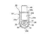
また、注出部23は、取付部22の中空胴体26と同様の断面形状すなわち、図3に示すように、互いに平行に対峙する側壁23aの上端を平坦の上部壁23bで連結し、両側壁23aの下端を円弧溝状の底壁23cにて連結した中空筒状に形成されて、流出路21を構成している。なお、取付部22と注出部23との連結部には、流出路21内を流れるビールBを整流にする分岐部29が設けられている。
【0018】
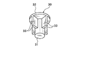
上記回転体30は、図1〜図3に示すように、流出路21内を流れるビールBの流れ方向に対して垂直方向に回転軸31を有する回転羽根にて形成されている。この回転体30(以下に回転羽根30という)は、例えばポリエチレン等のプラスチック製部材にて形成されており、図4に示すように、一端にフランジ部32を有する回転軸31と、回転軸31のフランジ部32側から先端部の手前側に、放射方向に延在する複数(図面では4枚の場合を示す)の羽根部33とで形成されている。このように形成される回転羽根30は、回転軸31のフランジ部32側がモータ40の駆動軸41に連結され、注出体20の注出部23の流出路21内に配設されて、流出路21を流れるビールBの流れ方向と逆方向及び同方向に回転し得るようになっている。
【0019】
上記回転羽根30を回転駆動するモータ40は、上記注出部23の上部壁23bに取り付けられて、注出部23の流出路21内に突出する駆動軸41に上記回転羽根30の回転軸31を連結することで、回転羽根30を流出路21内に配設し、流出路21を流れるビールBの流れ方向と逆方向及び同方向に回転羽根30を回転することができる。この場合、図2に示すように、注出部23の上部壁23bに凹所23dを設けて、この凹所23d内にモータ40の一部を挿入して、固定すれば、モータ40の取付を確実にすることができると共に、モータ40の外部への突出量を少なくすることができる。
【0020】
一方、上記保持部60は、上記注出体20と同様に、例えばポリエチレン等のプラスチック製部材にて形成されており、注出体20と一体に形成されている。この場合、保持部60は、上端が開口する略矩形箱状に形成されており、一端部が注出体20の中空胴体26から突出するブラケット部61を介して注出部23に連結され、他端側の底部に、ビール缶1の肩部3に係止可能な係止段部62が形成されている。また、保持部60内には、モータ40の駆動用電池50を収容可能な収容部の両端部にプラス又はマイナスの電極端子(図示せず)が配置されると共に、これら電極端子とモータ40とを接続するリード線52が配設されている。また、保持部60の他端側すなわちビール缶1の肩部3側には、モータ40と電池50の電気回路をON、OFFするスイッチである押しボタン式スイッチ54が配設されている。このように保持部60のビール缶1の肩部3側にスイッチ54を配設することにより、ビール缶1に取り付けられた取手4を持ってビールを注ぐ際に、取手を掴んだ手の親指又は人差し指でスイッチ54を操作することができる。したがって、ビールを注ぐ際のスイッチ操作を簡単にすることができると共に、泡の量や泡立ちのタイミング等の調整を自由に行うことができる。
【0021】
上記のように構成されるビール容器用注出器10を使用する場合は、まず、ビール缶1の口部2を閉塞するキャップ(図示せず)を取り外した後、口部2内に取付部22の挿入筒体24を挿入すると共に、保持部60に設けた係止段部62をビール缶1の肩部3に係止させて、注出器10を取り付ける。この際、保持部60をビール缶1の取手4の上方側に置く方が好ましい。そして、取手4を持って注出器10の注出部23を下方に傾けてグラスあるいはジョッキ等の容器(図示せず)内にビールBを注ぐ際に、取手4を掴んでいる手の親指あるいは人差し指等でスイッチ54をON操作してモータ40を駆動させて、回転羽根30を回転させることで、流出路21を流れるビールBに強制的に乱流を生じさせて撹拌して、きめの細かい泡を生成することができる。なおこの場合、ビールBの注ぎ始めはスイッチ54をON操作せずに、通常通りビールを注ぎ、グラス等の容器内にある程度ビールBが注がれたところで、スイッチ54をON操作すれば、ビールBの上面に最適な量の泡を作ることができる。この泡の調整は、スイッチ54をビール缶1の肩部3側に位置させてあるので、ビールBを注ぐ際に取手を掴んだ手の親指又は人差し指でスイッチ54を操作して、簡単に泡立ちを調整することができる。
【0022】
なお、上記実施形態では、回転羽根30の羽根部33が4枚の場合について説明したが、同様の作用効果を奏するものであれば羽根部33の枚数や形状は任意のものでよい。また、上記実施形態では、この発明の注出器を、2〜3リットル入りの大容量のビール缶に適用する場合について説明したが、プルトップ式の口部を有するビール缶やビン容器においても、取付部22を各形態の容器の口部に適合できるように形成すれば、これらプルトップ式の口部を有するビール缶やビン容器にも使用可能である。
【0023】
【発明の効果】
以上に説明したように、この発明のビール容器用注出器は、上記のように構成されているので、以下のような効果が得られる。
【0024】
(1)請求項1記載の発明によれば、ビール容器内のビールを注ぐ際に、モータを駆動させて回転体を強制的に回転させるため、この回転体の回転によってビールに撹拌エネルギが付与される。そのため、ビール流体には乱流が発生し、流出路内にある回転体近傍のビール流体微少空間内で大きな圧力差が時間的に激しく変動し、過飽和に存在するビール流体内の炭酸ガスがその自由エネルギを下げるために、極めて短時間に気体へ相分離する。したがって、安定したきめの細かい泡を立てることができる。
【0025】
(2)請求項2記載の発明によれば、ビールの流れ方向に対して垂直方向に回転軸を有する回転体をモータにて強制的に回転させるので、上記(1)に加えて更に乱流を発生し易くすることができ、より一層安定したきめの細かい泡を立てることができる。
【0026】
(3)請求項1,2記載の発明によれば、注出体の注出部に一端が連結される保持部に電池を収容すると共に、保持部の他端をビール容器の肩部に係止させて取り付けることができるので、注出器を安定した状態でビール容器に取り付けることができる。また、保持部のビール容器の肩部側にスイッチを配設することにより、ビール容器に取り付けられた取手を持ってビールを注ぐ際、取手を掴んだ手の指でスイッチを操作することができる。したがって、ビールを注ぐ際のスイッチ操作を簡単にすることができると共に、泡の量や泡立ちのタイミング等の調整を自由に行うことができる。
【図面の簡単な説明】
【図1】この発明のビール容器用注出器の使用状態を示す一部断面側面図である。
【図2】上記注出器の要部を示す断面図である。
【図3】この発明における注出体の注出部の形状を示す正面図である。
【図4】この発明における回転体を示す斜視図である。
【符号の説明】
1 ビール缶(ビール容器)
2 口部
3 肩部
10 注出器
20 注出体
21 流出路
22 取付部
23 注出部
30 回転羽根(回転体)
31 回転軸
40 モータ
50 モータ駆動用電池
52 リード線
54 スイッチ
60 保持部
62 係止段部[0001]
BACKGROUND OF THE INVENTION
The present invention relates to a beer container dispenser, and more particularly to a beer container dispenser having a foaming function.
[0002]
[Prior art]
In general, the foam of beer prevents carbon dioxide from escaping from the beer and prevents the beer from being oxidized by touching the air. Therefore, it is said that a fine creamy foamy beer increases the taste.
[0003]
Therefore, for example, when pouring beer in a beer container such as a beer can containing 2 liters or 3 liters into a container such as a glass or a mug, various devices have been made in the spout to improve foaming. As one of the means for improving foaming, there is known one in which a rotating body that rotates by the circulation of beer is arranged in the outflow passage of the spout (Japanese Utility Model Publication No. 3-50031, Japanese Utility Model Publication No. 3-38128). See the official gazette). In this structure, the rotating body is rotated by the beer flowing in the outlet channel of the spout, thereby generating turbulent flow and stirring the beer to improve foaming.
[0004]
[Problems to be solved by the invention]
However, since the rotation of the rotating body is influenced by the flow rate and flow rate of beer flowing through the outlet outlet of the spout, the ones described in the above-mentioned actual fairs 3-50031 and 3-38128 have stable foaming. There is a problem that cannot be obtained. Moreover, since the force in the outflow direction of beer and half the force in the rotation direction of the rotating body are contradictory to each other, the rotating body cannot be smoothly rotated and the foaming function is not sufficient.
[0005]
This invention was made in view of the above circumstances, and an object thereof is to provide a beer container pouring device that forcibly generates turbulent flow to improve foaming when pouring beer in a beer container. To do.
[0006]
[Means for Solving the Problems]
In order to achieve the above-mentioned object, the invention described in claim 1 has a mounting portion attached to the mouth portion of the beer container, and a pour-out portion extending outward from the mounting portion. A pouring body having an outflow passage communicating with the pouring body, a rotating body disposed in the outflow passage of the pouring body, a motor for rotationally driving the rotating body, and one end of the pouring portion of the pouring body A holding portion that is connected and can be engaged with the shoulder of the beer container at the other end, removably storing a battery for driving the motor in the holding portion, and connecting the motor to the battery. And a switch is provided on the shoulder side of the holding portion of the beer container .
[0007]
By comprising in this way, when pouring the beer in a beer container, since a rotary body is forcedly rotated by driving a motor, stirring energy is provided to beer by rotation of this rotary body. Therefore, a turbulent flow is generated in the beer fluid, and a large pressure difference fluctuates in time in the beer fluid minute space in the vicinity of the rotating body in the outflow path, and the carbon dioxide gas in the beer fluid existing in the supersaturation is In order to reduce free energy, phase separation into a gas is performed in a very short time. Therefore, it is possible to make stable fine bubbles. This means that part of the potential energy change of the beer fluid generated when pouring beer is completely different from the conventional mechanism in which the beer fluid is converted into turbulent flow by a rotating body or an obstacle. Is different.
[0008]
The invention according to claim 2 has a mounting portion attached to the mouth portion of the beer container, a pouring portion extending outward from the mounting portion, and an outflow passage communicating with the inside of the beer container. A rotating body, a rotating body that is disposed in the outflow path of the pouring body and has a rotation axis in a direction perpendicular to the flow direction of beer flowing in the outflow path, and a motor that rotationally drives the rotating body, A holding part that is connected at one end to the pouring part of the pouring body and can be locked to the shoulder part of the beer container, and the battery for driving the motor is detachably accommodated in the holding part. In addition, a lead wire for connecting the motor and the battery is disposed, and a switch is disposed on the shoulder portion side of the beer container of the holding portion .
[0009]
By configuring in this way, a rotating body having a rotation axis in a direction perpendicular to the flow direction of beer is forcibly rotated by a motor, so that turbulence is further generated in addition to the invention of claim 1. This makes it possible to make finer bubbles that are more stable and finer.
[0011]
Moreover, according to invention of Claim 1, 2, while storing a battery in the holding | maintenance part by which one end is connected with the extraction | pouring part of a pouring body, the other end of a holding | maintenance part is latched to the shoulder part of a beer container. Therefore, the dispenser can be attached to the beer container in a stable state. Also, by placing a switch on the shoulder side of the beer container of the holding part, when pouring beer with a handle attached to the beer container, the switch is operated with the thumb or index finger of the hand holding the handle Can do. Therefore, the switch operation when pouring beer can be simplified, and the amount of foam and the timing of foaming can be adjusted freely.
[0012]
DETAILED DESCRIPTION OF THE INVENTION
EMBODIMENT OF THE INVENTION Below, embodiment of the extractor for beer containers of this invention is described in detail based on an accompanying drawing.
[0013]
FIG. 1 is a partially sectional side view showing a use state of an example of a beer container dispenser of the present invention, and FIG. 2 is a sectional view showing an essential part of the dispenser.
[0014]
The pouring device 10 includes a
[0015]
The said pouring
[0016]
In this case, as shown in FIG. 2, the
[0017]
The
[0018]
As shown in FIGS. 1 to 3, the rotating
[0019]
The
[0020]
On the other hand, the holding portion 60 is formed of a plastic member such as polyethylene, for example, similarly to the
[0021]
When using the beer container pouring device 10 configured as described above, first, a cap (not shown) that closes the mouth 2 of the beer can 1 is removed, and then a mounting portion is provided in the mouth 2. While inserting 22
[0022]
In addition, although the said embodiment demonstrated the case where the
[0023]
【The invention's effect】
As described above, since the beer container dispenser of the present invention is configured as described above, the following effects can be obtained.
[0024]
(1) According to the first aspect of the present invention, when pouring beer in a beer container, the motor is driven to forcibly rotate the rotating body. Is done. Therefore, a turbulent flow is generated in the beer fluid, and a large pressure difference fluctuates in time in the beer fluid minute space in the vicinity of the rotating body in the outflow path, and the carbon dioxide gas in the beer fluid existing in the supersaturation is In order to reduce free energy, phase separation into a gas is performed in a very short time. Therefore, it is possible to make stable fine bubbles.
[0025]
(2) According to the invention described in claim 2, since the rotating body having the rotation axis in the direction perpendicular to the flow direction of beer is forcibly rotated by the motor, in addition to the above (1), further turbulent flow Can be easily generated, and more stable fine bubbles can be formed.
[0026]
(3) According to the first and second aspects of the invention, the battery is accommodated in the holding portion whose one end is connected to the pouring portion of the pouring body, and the other end of the holding portion is engaged with the shoulder portion of the beer container. Since it can be stopped and attached, the dispenser can be attached to the beer container in a stable state. Moreover, by arranging a switch on the shoulder side of the beer container of the holding part, when pouring beer with a handle attached to the beer container, the switch can be operated with the finger of the hand holding the handle. . Therefore, the switch operation when pouring beer can be simplified, and the amount of foam and the timing of foaming can be adjusted freely.
[Brief description of the drawings]
FIG. 1 is a partial cross-sectional side view showing a use state of a beer container dispenser of the present invention.
FIG. 2 is a cross-sectional view showing the main part of the dispenser.
FIG. 3 is a front view showing the shape of the extraction portion of the extraction body in the present invention.
FIG. 4 is a perspective view showing a rotating body in the present invention.
[Explanation of symbols]
1 Beer can (beer container)
2 Mouth 3 Shoulder 10 Pouring
31 Rotating
Claims (2)
上記注出体の流出路内に配設される回転体と、
上記回転体を回転駆動するモータと、
上記注出体の注出部に一端が連結され、他端がビール容器の肩部に係止可能な保持部と、を具備し、
上記保持部に、モータの駆動用電池を着脱可能に収容すると共に、モータと電池を接続するリード線を配設し、かつ、保持部のビール容器の肩部側にスイッチを配設してなることを特徴とするビール容器用注出器。While having a mounting part attached to the mouth part of the beer container, and a pouring part extending outward from the mounting part, a pouring body having an outflow passage communicating with the inside of the beer container,
A rotating body disposed in the outflow passage of the extraction body;
A motor for rotationally driving the rotating body;
One end is connected to the pouring portion of the pouring body, and the other end includes a holding portion that can be locked to the shoulder portion of the beer container,
A battery for driving the motor is detachably accommodated in the holding part, a lead wire for connecting the motor and the battery is provided, and a switch is provided on the shoulder side of the beer container of the holding part. An extractor for beer containers.
上記注出体の流出路内に配設され、流出路内を流れるビールの流れ方向に対して垂直方向に回転軸を有する回転体と、
上記回転体を回転駆動するモータと、
上記注出体の注出部に一端が連結され、他端がビール容器の肩部に係止可能な保持部と、を具備し、
上記保持部に、モータの駆動用電池を着脱可能に収容すると共に、モータと電池を接続するリード線を配設し、かつ、保持部のビール容器の肩部側にスイッチを配設してなることを特徴とするビール容器用注出器。While having a mounting part attached to the mouth part of the beer container, and a pouring part extending outward from the mounting part, a pouring body having an outflow passage communicating with the inside of the beer container,
A rotating body that is disposed in the outflow path of the extraction body and has a rotation axis in a direction perpendicular to the flow direction of beer flowing in the outflow path;
A motor for rotationally driving the rotating body;
One end is connected to the pouring portion of the pouring body, and the other end includes a holding portion that can be locked to the shoulder portion of the beer container,
A battery for driving the motor is detachably accommodated in the holding part, a lead wire for connecting the motor and the battery is provided, and a switch is provided on the shoulder side of the beer container of the holding part. An extractor for beer containers.
Priority Applications (2)
| Application Number | Priority Date | Filing Date | Title |
|---|---|---|---|
| JP24691499A JP3963243B2 (en) | 1999-09-01 | 1999-09-01 | Beer container dispenser |
| TW89100659A TW449567B (en) | 1999-09-01 | 2000-01-17 | Pour device for beer container |
Applications Claiming Priority (1)
| Application Number | Priority Date | Filing Date | Title |
|---|---|---|---|
| JP24691499A JP3963243B2 (en) | 1999-09-01 | 1999-09-01 | Beer container dispenser |
Publications (2)
| Publication Number | Publication Date |
|---|---|
| JP2001072075A JP2001072075A (en) | 2001-03-21 |
| JP3963243B2 true JP3963243B2 (en) | 2007-08-22 |
Family
ID=17155638
Family Applications (1)
| Application Number | Title | Priority Date | Filing Date |
|---|---|---|---|
| JP24691499A Expired - Fee Related JP3963243B2 (en) | 1999-09-01 | 1999-09-01 | Beer container dispenser |
Country Status (2)
| Country | Link |
|---|---|
| JP (1) | JP3963243B2 (en) |
| TW (1) | TW449567B (en) |
Families Citing this family (2)
| Publication number | Priority date | Publication date | Assignee | Title |
|---|---|---|---|---|
| JP6981653B2 (en) * | 2018-01-23 | 2021-12-15 | 株式会社千石 | Liquid server and foam generator |
| JP7005434B2 (en) * | 2018-06-15 | 2022-01-21 | サントリーホールディングス株式会社 | Manual whipping beer server |
-
1999
- 1999-09-01 JP JP24691499A patent/JP3963243B2/en not_active Expired - Fee Related
-
2000
- 2000-01-17 TW TW89100659A patent/TW449567B/en not_active IP Right Cessation
Also Published As
| Publication number | Publication date |
|---|---|
| JP2001072075A (en) | 2001-03-21 |
| TW449567B (en) | 2001-08-11 |
Similar Documents
| Publication | Publication Date | Title |
|---|---|---|
| US7384182B2 (en) | Automatic stirring travel beverage container | |
| CN1956659B (en) | Adapter for blender pitcher | |
| CN104144860B (en) | a syrup dish lid | |
| US3220587A (en) | Bottle with self-contained drinking straw | |
| CA2064737A1 (en) | Container | |
| JP3963243B2 (en) | Beer container dispenser | |
| JP3585330B2 (en) | Beverage container | |
| JP2731495B2 (en) | Electric razor | |
| ES3014032T3 (en) | A pouring attachment device for a beverage container | |
| US4566507A (en) | Liquid beverage dispenser | |
| JPH09226785A (en) | Liquid discharging container | |
| JP2002238779A (en) | Whisk | |
| JP3009188U (en) | Effervescent beverage can container | |
| CN213832796U (en) | Multifunctional wine bottle | |
| JPH0717538A (en) | Refill type container | |
| JP2002145398A (en) | Auxiliary case for beer container | |
| JP2005162222A (en) | Liquid ejection apparatus | |
| JP2003033292A (en) | Bubble generator | |
| JPH07330003A (en) | Pump container | |
| JP2021195165A (en) | Plug body of beverage container | |
| JP2004043033A (en) | Beer foam dispenser | |
| JP3652467B2 (en) | Cap for liquid ejection container | |
| KR200166630Y1 (en) | Sweets containers | |
| JP4429367B1 (en) | Beverage container | |
| JP3012182U (en) | Effervescent beverage can container |
Legal Events
| Date | Code | Title | Description |
|---|---|---|---|
| A621 | Written request for application examination |
Free format text: JAPANESE INTERMEDIATE CODE: A621 Effective date: 20041217 |
|
| A977 | Report on retrieval |
Free format text: JAPANESE INTERMEDIATE CODE: A971007 Effective date: 20060822 |
|
| A131 | Notification of reasons for refusal |
Free format text: JAPANESE INTERMEDIATE CODE: A131 Effective date: 20060920 |
|
| A521 | Written amendment |
Free format text: JAPANESE INTERMEDIATE CODE: A523 Effective date: 20061026 |
|
| TRDD | Decision of grant or rejection written | ||
| A01 | Written decision to grant a patent or to grant a registration (utility model) |
Free format text: JAPANESE INTERMEDIATE CODE: A01 Effective date: 20070516 |
|
| A61 | First payment of annual fees (during grant procedure) |
Free format text: JAPANESE INTERMEDIATE CODE: A61 Effective date: 20070516 |
|
| R150 | Certificate of patent or registration of utility model |
Free format text: JAPANESE INTERMEDIATE CODE: R150 |
|
| LAPS | Cancellation because of no payment of annual fees |